

Digitronic CamCon DC50, CamCon DC51 User Manual
Digital Cam Switch Unit
CamCon DC50/51
Digitronic Automationsanlagen GmbH
Steinbeisstraße 3 • D - 72636 Frickenhausen • Tel. (+49)7022/40590-0 • Fax -10
Auf der Langwies 1 • D - 65510 Hünstetten-Wallbach • Tel.(+49)6126/9453-0 • Fax -42
Internet: http://www.digitronic.com • E-Mail: mail@digitronic.com
2 rue René Laennec 51500 Taissy France
Fax: 03 26 85 19 08, Tel : 03 26 82 49 29
E-mail:hvssystem@hvssystem.com
Site web : www.hvssystem.com

Digitronic Digital Cam Switch Unit
Automationsanlagen GmbH CamCon DC50/51
For your attention
This instruction manual relates to the CamCon DC50/51 from 10/2003. The company Digitronic
Automationsanlagen GmbH reserves the right to make changes which present an improvement of the
quality or functionality of the device without prior notice. The instruction manual was created with great
care, although it may not be error-proof. We would be grateful for any communication relating to any
errors you may have found.
UP-date
You can also obtain this instruction manual on the Internet at http://www.digitronic.com in the latest
version as PDF file.
Qualified personnel
This device may only be started and operated by qualified staff. By qualified we mean personnel who
are entitled to handle, to earth and to lable devices, systems and power circuits in accordance with the
technology safety standards.
Liability
(1) The supplier is liable for damages caused by himself or by the owner of the rights up to the sum of
the sales price. He is not liable for loss of profits, forfeited savings, intermediate and successive
damages.
(2) The above mentioned limits to liability do not apply to insurance of named characteristics and
damages which were caused deliberately or through negligence.
Protection
The CamCon DC50/51 and this instruction manual are protected by copyright. All rights are reserved.
Neither the CamCon DC50/51, nor this document may be copied as a whole or partially, photocopied,
reproduced, translated or transferred to electronic media of any kind or into machine readable format
without prior written permission by the company Digitronic Automationsanlagen GmbH.
Note: We have examined the devices of the CamCon series for year 2000 compatibility and
have not found any adverse effects on any functions.
Note: CamCon is a registered trademark of the company Firma Digitronic
Automationsanlagen GmbH.
Note: The devices of the CamCon series comply with the standards for electromagnetic
compatibility: EN 55011, EN 55022, EN 55024 Part 2, EN 50082 Part 2, ENV 50140,
VDE 0843 Part 2, VDE 0843 Part 4, VDE 0871, VDE 0875 Part 3 ("N"),
VDE 0875 Part 11, VDE 0877 Part 2, IEC 801 Part 3, IEC 801 Part 2, IEC 801 Part 4,
IEC 801 Part 5.
(c) Copyright 1992 - 2004 / File: DC50E.DOC
Digitronic Automationsanlagen GmbH
Auf der Langwies 1
D-65510 Hünstetten - Wallbach
Tel. (+49)6126/9453-0 Fax. (+49)6126/9453-42
Internet: http://www.digitronic.com
E-Mail: mail@digitronic.com
,Version from: Aug. 04 Page: 2
2 rue René Laennec 51500 Taissy France
Fax: 03 26 85 19 08, Tel : 03 26 82 49 29
E-mail:hvssystem@hvssystem.com
Site web : www.hvssystem.com

Digitronic Digital Cam Switch Unit
Automationsanlagen GmbH CamCon DC50/51
TABLE OF CONTENTS
1. Introduction..........................................................................................................................................8
2. Operating Pinciples..............................................................................................................................9
2.1. Speed Compensation .....................................................................................................................10
2.1.1. Measuring delay time for Speed Compensation..........................................................................12
2.1.1.1. Measuring delay time through actual differences.....................................................................12
2.1.1.2. Measuring delay time by means of different measuring points.................................................12
2.1.2. Speed Compensation using off-centre pressure, e.g. brake functions........................................13
2.1.3. Separate delay time for Speed Compensation of switch-ON and switch-OFF points.................14
2.2. Time - Cam.....................................................................................................................................14
3. Installation..........................................................................................................................................15
3.1. Dimensions.....................................................................................................................................15
4. Electrical connections........................................................................................................................16
4.1. Pin allocation of the CamCon .........................................................................................................16
4.1.1. Pin allocation of the analog output...............................................................................................16
4.1.2. Pin allocation of the SSI measuring system.................................................................................16
4.1.3. Pin allocation of the incremental measuring system....................................................................17
4.1.4. Pin allocation of the inputs...........................................................................................................17
4.1.5. Pin allocation of the outputs.........................................................................................................17
4.1.6. Pin allocation of the voltage supply..............................................................................................18
4.1.7. Pin allocation of the serial interface.............................................................................................18
4.1.7.1. Pin allocation of the serial RS232 interface..............................................................................18
4.1.7.2. Pin allocation of the serial RS485 interface..............................................................................19
4.1.8. Pin allocation of the external interface.........................................................................................20
4.2. The measuring system....................................................................................................................21
4.2.1. SSI Measuring system input........................................................................................................21
4.2.2. Parallel measuring system input..................................................................................................21
4.2.3. Incremental measuring system input...........................................................................................22
4.2.3.1. Incremental measuring system input with 5V RS422 level.......................................................22
4.2.3.2. Incremental measuring system input with 24V PNP level.........................................................22
4.2.3.3. Incremental Hiperface measuring system input with SINCOS level.........................................23
4.2.4. Analog measuring system input...................................................................................................23
4.2.5. PLL measuring system input........................................................................................................24
4.2.6. Timer as a measuring system......................................................................................................24
4.2.7. RS232 as a measuring system....................................................................................................24
4.3. The outputs.....................................................................................................................................25
4.3.1. The 40mA outputs (only CamCon device with aluminium back wall)..........................................25
4.3.2. The 500mA outputs......................................................................................................................25
4.4. The inputs.......................................................................................................................................25
4.5. Precautionary measures for welding work......................................................................................25
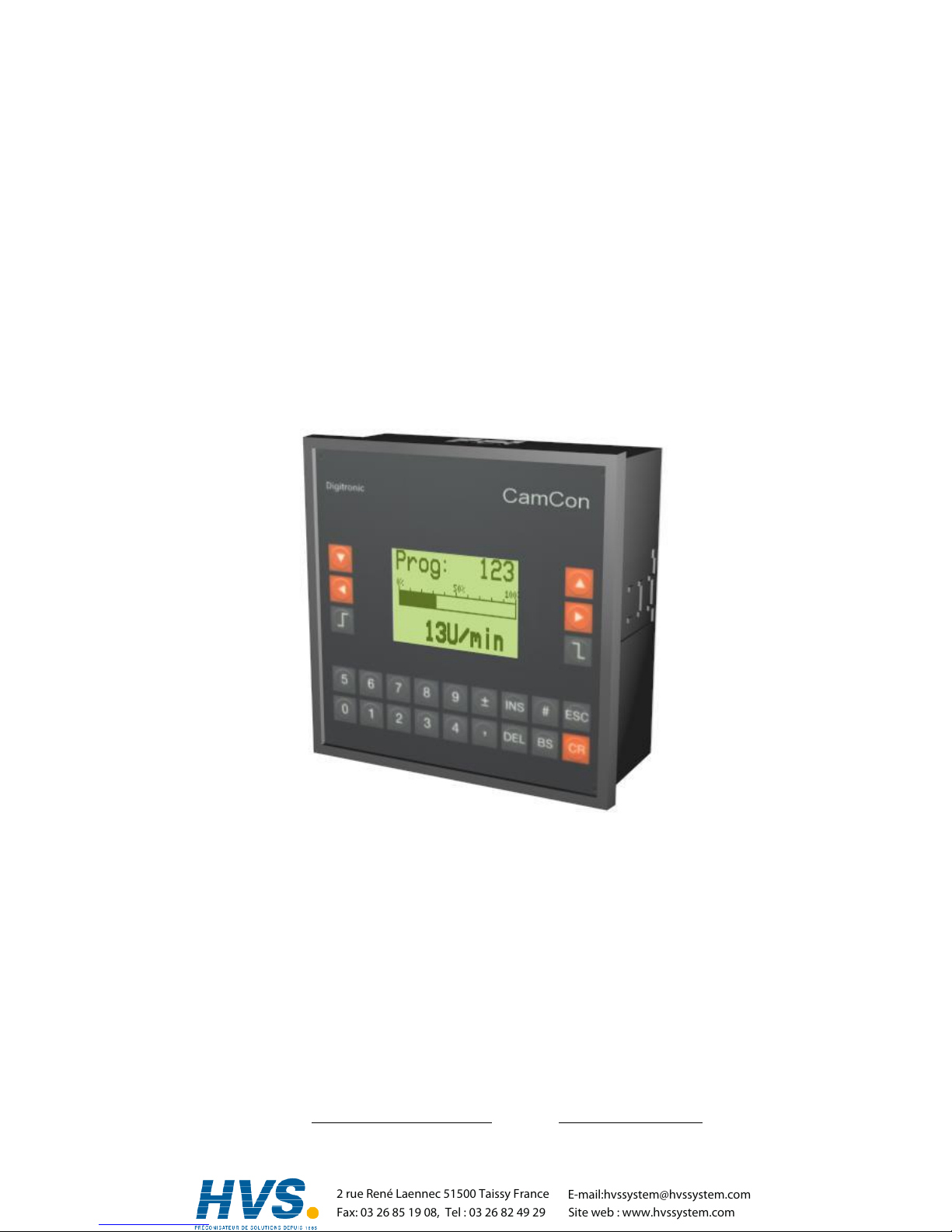
5. Outline of the operator terminal.........................................................................................................26
5.1. Frontview CamCon.........................................................................................................................26
5.2. The liquid crystal display (LCD) ......................................................................................................26
5.3. Contrast setting...............................................................................................................................26
5.4. The keyboard..................................................................................................................................26
5.5. Outline of key functions...................................................................................................................27
5.6. Menu selection................................................................................................................................27
5.7. Selection of a menu point ...............................................................................................................27
5.8. Text input........................................................................................................................................28
6. Commissioning ..................................................................................................................................29
7. Operation of the CamCon..................................................................................................................31
7.1. The main menu...............................................................................................................................31
7.2. The standard display.......................................................................................................................31
,Version from: Aug. 04 Page: 3
2 rue René Laennec 51500 Taissy France
Fax: 03 26 85 19 08, Tel : 03 26 82 49 29
E-mail:hvssystem@hvssystem.com
Site web : www.hvssystem.com

Digitronic Digital Cam Switch Unit
Automationsanlagen GmbH CamCon DC50/51
7.2.1. Changing the display....................................................................................................................31
7.2.2. Program change ..........................................................................................................................32
7.2.3. Program name.............................................................................................................................32
7.3. Cam programming..........................................................................................................................33
7.3.1. Output selection for programming ...............................................................................................33
7.3.2. Program selection for programming............................................................................................34
7.3.3. Programming the delay time/speed compensation......................................................................34
7.3.4. Programing Time-Cams...............................................................................................................35
7.3.5. Programming the output name....................................................................................................36
7.3.6. Cam Input ....................................................................................................................................36
7.3.7. Adding cams................................................................................................................................37
7.3.8. Cam Teach - In............................................................................................................................37
7.3.9. Cam Search.................................................................................................................................37
7.3.10. Cam deletion..............................................................................................................................38
7.3.11. Output (cam track) deletion .......................................................................................................38
7.3.12. Copying programmed outputs (cam tracks)...............................................................................39
7.3.13. Shifting cam tracks ....................................................................................................................39
7.3.14. Deleting programs......................................................................................................................40
7.3.15. Copying programs......................................................................................................................40
7.3.16. Examples for cam programming................................................................................................41
7.3.16.1. First cam programming...........................................................................................................41
7.3.16.2. Programming additional cams on an output...........................................................................42
7.3.16.3. Deletion of a particular cam....................................................................................................43
7.3.17. Programming analog cams........................................................................................................44
7.3.17.1. Creating the first analog cam..................................................................................................45
7.3.17.2. Adding an analog cam............................................................................................................45
7.3.17.3. Changing the analog cam.......................................................................................................45
7.4. Unit configuration (system setting)..................................................................................................46
7.4.1. Measuring system........................................................................................................................46
7.4.1.1. The standard measuring systems.............................................................................................46
7.4.1.2. The actual position hysteresis...................................................................................................46
7.4.1.3. Controlling the measuring system.............................................................................................47
7.4.1.4. The electronic gear...................................................................................................................48
7.4.1.4.1. Electronically changing the rotation direction.........................................................................48
7.4.1.5. The display format of the actual position..................................................................................48
7.4.1.6. Configuration of a special measuring system...........................................................................49
7.4.1.6.1. SSI - measuring system.........................................................................................................49
7.4.1.6.2. Parallel - Gray measuring system..........................................................................................50
7.4.1.6.3. Incremental - measuring system............................................................................................50
7.4.1.6.4. Multiturn measuring system with electronic gear...................................................................51
7.4.1.6.5. PLL measuring system ..........................................................................................................52
7.4.1.6.6. Timer way simulation (time emitter).......................................................................................52
7.4.1.6.7. RS232 measuring system......................................................................................................53
7.4.1.6.8. AG615 - Single - Multiturn - Measuring system.....................................................................53
7.4.1.6.9. SIM - measuring system simulator ........................................................................................54
7.4.1.6.10. HIPER i.e. incremental - measuring system with Roll - Over - funktion..............................54
7.4.1.7. Deleting the special measuring system ....................................................................................55
7.4.2. The measuring offset...................................................................................................................56
7.4.2.1. Zero offset with rotatory movements.........................................................................................56
7.4.2.2. Measuring offset with a linear moved system...........................................................................56
7.4.2.3. Zero offset with linear movements............................................................................................56
7.4.2.4. Actual position preset................................................................................................................57
7.4.3. The speed adjustment.................................................................................................................58
7.4.3.1. The speed factor.......................................................................................................................58
7.4.3.2. The display format of the speed display...................................................................................58
7.4.3.3. Range adjustment of the speed display....................................................................................58
7.4.3.4. Accuracy of the speed display..................................................................................................59
7.4.3.5. Display, Type ............................................................................................................................59
,Version from: Aug. 04 Page: 4
2 rue René Laennec 51500 Taissy France
Fax: 03 26 85 19 08, Tel : 03 26 82 49 29
E-mail:hvssystem@hvssystem.com
Site web : www.hvssystem.com

Digitronic Digital Cam Switch Unit
Automationsanlagen GmbH CamCon DC50/51
7.4.4. Cable length / Cycle time.............................................................................................................60
7.4.4.1. The cable length .......................................................................................................................60
7.4.4.2. The cycle time of the CamCon..................................................................................................60
7.4.5. The special outputs......................................................................................................................60
7.4.5.1. The security output....................................................................................................................60
7.4.5.2. The output of the actual position...............................................................................................61
7.4.5.3. Direction output.........................................................................................................................61
7.4.5.4. The standstill output..................................................................................................................61
7.4.5.5. The hysteresis...........................................................................................................................61
7.4.5.6. The analog speed output..........................................................................................................62
7.4.5.7. Configuration of the analog cams.............................................................................................62
7.4.5.8. The analog position output........................................................................................................64
7.4.6. System upgrading........................................................................................................................64
7.4.6.1. Setting the inputs......................................................................................................................64
7.4.6.2. Setting the outputs....................................................................................................................64
7.4.6.3. Setting the outputs with speed compensation..........................................................................64
7.4.6.4. Setting the keyboard lock..........................................................................................................64
7.4.6.5. Error - aknowledging Input (EQ)...............................................................................................64
7.4.6.6. Input for enableling Outputs......................................................................................................64
7.4.6.7. Setting the external program selection.....................................................................................65
7.4.6.8. Setting the program selection mode.........................................................................................65
7.4.7. Masterprogram.............................................................................................................................66
7.5. Unit configuration............................................................................................................................67
7.5.1. User key allocation.......................................................................................................................67
7.5.1.1. Creating a new user key...........................................................................................................67
7.5.1.2. Deletion of a user key...............................................................................................................68
7.5.1.3. Checking the key configuration.................................................................................................68
7.5.2. Complete deletion........................................................................................................................69
7.5.3. Unit configuration.........................................................................................................................70
7.5.3.1. Setting the serial interface ........................................................................................................70
7.5.3.1.1. The "Cam-BUS" communication mode..................................................................................70
7.5.3.1.2. The "Standard" communication mode...................................................................................70
7.5.3.1.3. The "Multiuser" communication mode...................................................................................70
7.5.3.1.4. The "S5 - L1" communication mode......................................................................................70
7.5.3.1.5. The "3964(R)" communication mode.....................................................................................70
7.5.3.1.6. Input of the unit number.........................................................................................................71
7.5.3.1.7. Programming via remote .......................................................................................................71
7.5.3.2. Additional device options..........................................................................................................71
7.5.3.2.1. PLC Logic Module..................................................................................................................71
7.5.3.2.1.1. Examples for using the PLC logic module..........................................................................71
7.5.3.2.2. PLC Logic Module with text display.......................................................................................72
7.5.3.3. Analog outputs..........................................................................................................................73
7.5.3.3.1. Clearing the integrated analog outputs..................................................................................73
7.5.3.3.2. Adjusting the integrated analog outputs.................................................................................73
7.5.3.3.3. External analog outputs.........................................................................................................73
7.5.3.4. Locking EEProm memory.........................................................................................................74
7.5.4. Language.....................................................................................................................................75
7.5.5. Configure user .............................................................................................................................75
7.5.5.1. User text....................................................................................................................................75
7.5.5.2. User-Menu/OP-functions..........................................................................................................76
7.5.6. Configure Hardware.....................................................................................................................76
7.5.6.1. CP16 Module............................................................................................................................76
8. Device info.........................................................................................................................................77
8.1. Stack Info........................................................................................................................................79
9. Error messages and removal of errors (FAQ)...................................................................................80
9.1. Problem: Display shows "No contact to unit: XX"...........................................................................80
9.2. Problem: "Pos - Err:1".....................................................................................................................80
9.3. Problem: "Pos - Err:2".....................................................................................................................80
9.4. Problem: "Pos - Err:3".....................................................................................................................81
,Version from: Aug. 04 Page: 5
2 rue René Laennec 51500 Taissy France
Fax: 03 26 85 19 08, Tel : 03 26 82 49 29
E-mail:hvssystem@hvssystem.com
Site web : www.hvssystem.com

Digitronic Digital Cam Switch Unit
Automationsanlagen GmbH CamCon DC50/51
9.5. Problem: "Pos - Err:5".....................................................................................................................81
9.6. Problem: An "Pos-Error:" occurs during operation..........................................................................81
9.7. Problem: "RAM-Full" = RAM memoryis full.....................................................................................81
9.8. Problem: The EEProm memory is full.............................................................................................82
9.9. Problem: Outputs will not activate...................................................................................................82
9.10. Problem: "Out - Error"...................................................................................................................82
9.11. Problem: Error in the EEPROM....................................................................................................82
9.12. Problem: "Error ???".....................................................................................................................82
9.13. Problem: "Clear...."........................................................................................................................83
10. Menu outline.....................................................................................................................................84
11. Calculation EEPROM cam storage..................................................................................................85
12. Calculation the RAM storage-requirement for CamCon..................................................................86
13. Technical data of the CamCon........................................................................................................87
14. Key word table .................................................................................................................................88
,Version from: Aug. 04 Page: 6
2 rue René Laennec 51500 Taissy France
Fax: 03 26 85 19 08, Tel : 03 26 82 49 29
E-mail:hvssystem@hvssystem.com
Site web : www.hvssystem.com

Digitronic Digital Cam Switch Unit
Automationsanlagen GmbH CamCon DC50/51
1. Introduction
Electronic Cam Switch Units have been successfully used in industry for a long time. Experiences
collected in close liaison with users over the years have been included in the development of the
CamCon series. The result is a compact digital cam switch unit which is user friendly and reliable to a
high degree. The following characteristics testify the excellence of the CamCon:
* Tested and reliable hardware
* Short-circuit-proof outputs
* Graphic liquid crystal display with 128x64 pixels in the CamCon DC50,51.
* Large and clearly visible 7-Segment display for program, position and speed on
CamCon DC30,33 and 40.
* Any number of cams per output can be programmed.
* Up to 32000 Programs for product administration
* Master, for example: machine cams
* Optimising switch points when machine is in operation
* Compensation of mechanical delay time of switch components for switch-ON and switch-OFF
points can be set in steps of 100µs separately (DTC = delay time or Speed Compensation).
* Position - Triggert - Time - Cams
* Power supply 24V DC +/- 20%
* Mounting of suspension rails to EN 50022 on CamCon DC16 and 90
* Switchboard panel standard casing 144 x 144 x 63mm to DIN 43700 on CamCon DC33,40 and 51
* S5 Components group for S5 115U, 135U and 155U on CamCon DC115
* S7 Components group for S7 300 on CamCon DC300
* AB Components group for ControlLogix 1756 on CamCon 1756-DICAM
* S5 Switch-ON via PG interface with L1 - Bus on CamCon DC16,40,50,51 and 90
* PLC Logic Module (optional)
* Shift register (optional)
* OP - Functions
* Analog outputs (optional)
Cam switch units are used wherever switching operations are periodically repeated. Digital cam switch
units are an optimum replacement of mechanical units and offer in addition many other advantages,
such as:
* Simplification of mounting and adjustment operations
* Repeatable adjustment facility
* Standardised for almost all areas of application
* Reliability
* High switch speed
* Speed Compensation
* Product administration for quick format change
,Version from: Aug. 04 Page: 7
2 rue René Laennec 51500 Taissy France
Fax: 03 26 85 19 08, Tel : 03 26 82 49 29
E-mail:hvssystem@hvssystem.com
Site web : www.hvssystem.com
Digitronic Digital Cam Switch Unit
Automationsanlagen GmbH CamCon DC50/51
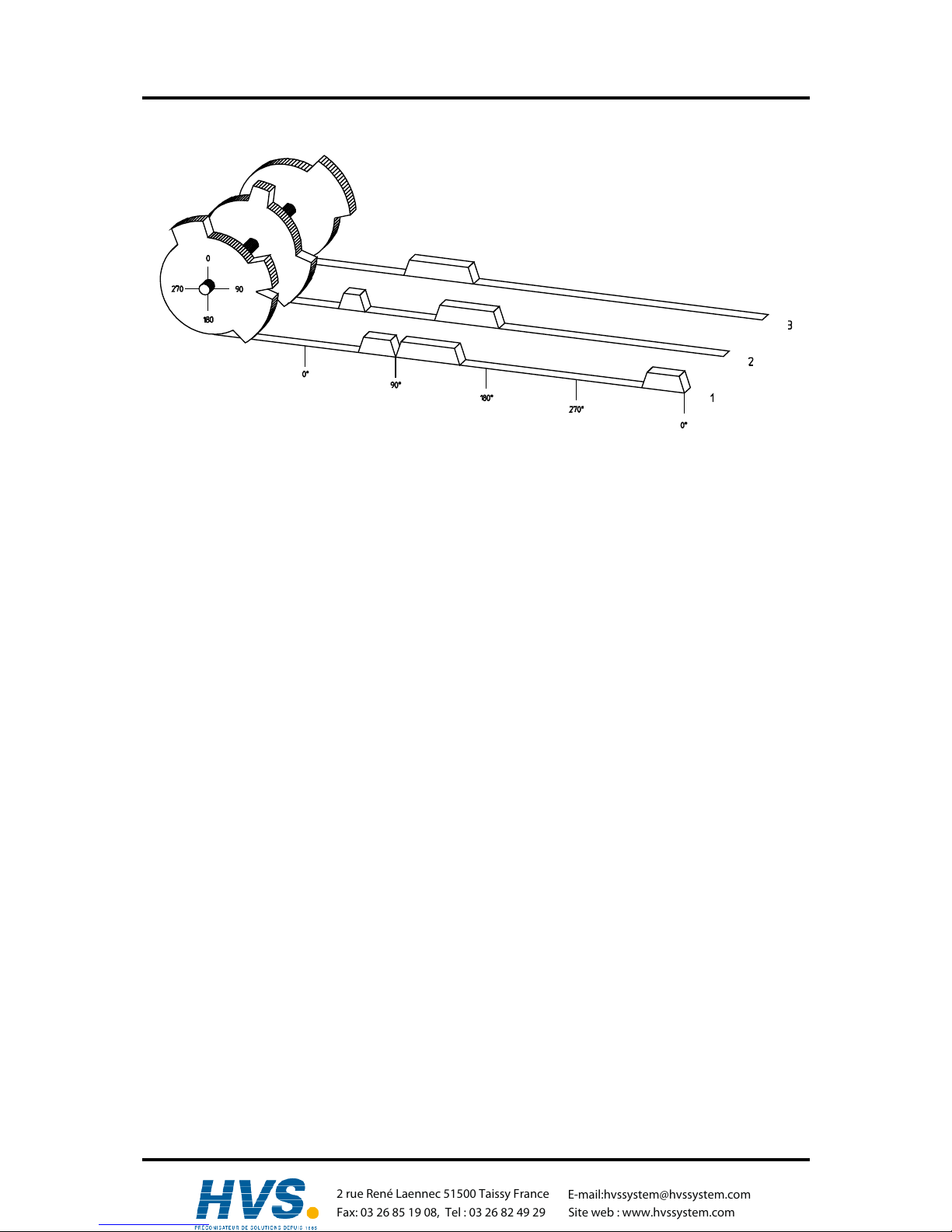
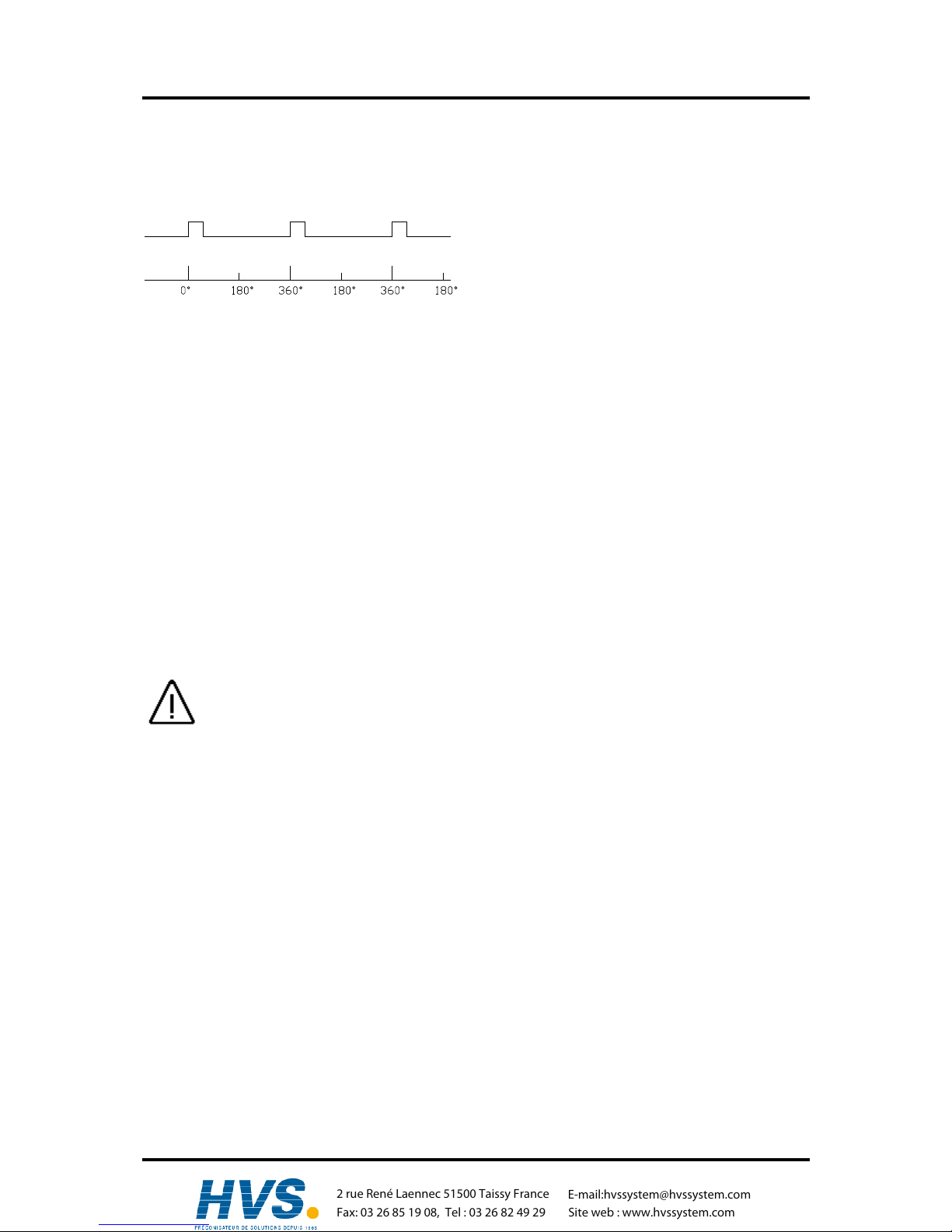
2. Operating Pinciples
Diagram: Principles of a Cam Switch Unit
A principle for better comprehension of the function of a Cam Switch Unit is here presented. It has 3
outputs with the following cams:
Output 1: Cam 1: Switch-ON position60° Switch-OFF position 85°
Cam 2: Switch-ON position95° Switch-OFF position 145°
Cam 3: Switch-ON position325° Switch-OFF position 355°
Output 2: Cam 1: Switch-ON position5° Switch-OFF position 20°
Cam 2: Switch-ON position95° Switch-OFF position 145°
Output 3: Cam 1: Switch-ON position30° Switch-OFF position 85°
The positions of the output signals, here presented as three tracks, occur when the three cam disks
turn anti-clockwise past a sensor, which scans the cams on the 0°-axis.
In a mechanical cam switch unit, the switch interval, i.e. the range between switch-ON and switch-OFF
position are determined by the length of the cam. The length and the position of the cam can only be
varied marginally and this is mechanically highly demanding and time consuming. With CamCon such
adjustments can be realised in a fraction of time; in addition, there can be any number of tracks. A
measuring system which is fitted to the device reports the position to the CamCon. The CamCon
compares it with the programmed switch-ON and Switch-OFF positions of all outputs. If the position
lies in the range of a programmed switch-ON / switch-OFF position (cam), then the respective outputs
are active.
,Version from: Aug. 04 Page: 8
2 rue René Laennec 51500 Taissy France
Fax: 03 26 85 19 08, Tel : 03 26 82 49 29
E-mail:hvssystem@hvssystem.com
Site web : www.hvssystem.com
Digitronic Digital Cam Switch Unit
Automationsanlagen GmbH CamCon DC50/51
2.1. Speed Compensation
Each mechanical switch component (e.g. shield, magnetic valve) has a delay time, i.e. the time
between the start signal and the actual switching of the contacts. In processes where positioning is
executed on a moving system, this can cause problems. If such a process is driven with different
speeds, different positions are caused. To avoid this happening, new timings for the switch signals of
each speed would have to be calculated.
In order to ilustrate the complicated issues surrounding delay time or speed compensation, this will be
shown on the example of a packaging machine. In the process shown in the diagram, a glue point has
to be placed in an exactly defined spot on a moving paper track.
magnetic valve
glue nozzle
drop
paper
Points where the glue
hits the paper at the
different speeds .
paper track
encoder
CamCon
The system has the following parameters:
v
p
- Speed of the paper track
v
T
- Falling speed of the drop of glue
d - Distance between the glue nozzle and
the paper track
T
MV
- Delay time of the magnetic valve
Without speed compensation the following would happen:
As soon as the measuring system has reached a certain position, the CamCon sends a signal to the
magnetic valve. The glue nozzle opens for a short time during which a drop of glue ejects. Between the
start of the impulse and the exit of the drop time passes, which is mainly caused by the delay time of
the magnetic valve T
MV.
. A further delay is caused by the time which the droplet needs to pass the
distance between the glue nozzle and the surface of the paper.
This flight time is calculated as follows:
t
Flight
=
d
v
T
In total there the delay time is tFlight+T
MV.
During this time the paper track moves on by a specific
distance x.
It would now be possible to move the position, where the magnetic valve is switched on, forward by a
specific amount, so that the glue droplet hits the same spot again as during standstill. In this way a
speed compensation is created which works only at a specific speed of the paper. As soon as the
speed of the device and consequently that of the paper track is, for example, doubled, the hit point of
the glue droplet is shifted by the distance x, so that, without any speed compensation, it would move
backward by double the distance (2 ⋅ x) in total.
The automatic speed compensation of the CamCon makes it now possible to drive processes with
variable speed; CamCon registers the speed of the device continuously and adjusts the cams which
determine the switch time points "On Line" depending on the speed. This has the effect that the
outputs for the switch components are switched ON or OFF earlier. The direction of the movement is
of no significance in this instance.
,Version from: Aug. 04 Page: 9
2 rue René Laennec 51500 Taissy France
Fax: 03 26 85 19 08, Tel : 03 26 82 49 29
E-mail:hvssystem@hvssystem.com
Site web : www.hvssystem.com

Digitronic Digital Cam Switch Unit
Automationsanlagen GmbH CamCon DC50/51
A small example in figures was designed to eludicate:
Supposing the drive cylinder with the measuring system has a circumference of 360mm, so that one
millimeter of the circumference corresponds to exactly one angle degree of the measuring system.
The device has the following parameters:
v
droplet
= 20m/s
d = 20cm
T
MV
= 20ms
This results in the following flight time of the droplet:
tFlight=
d
v
T
=
0,2m
20m/s
= 10ms
The total delay time is then Tdead
, altogether
= TMV + tFlight = 20ms + 10ms = 30ms
During this time the paper track moves on by the distance x = v
paper
⋅ T
total delay.
= 1m/s ⋅ 30ms =
30mm. In order to compensate the delay time, the switch point for the magnetic valve must be moved
forward by 30°.
If the speed of the device and consequently that of the paper is doubled v
paper
, then the distance x is
also doubled by the speed of the paper track. In this case the switch point must be moved by 60°.
Note: Please take into account in these explanations that delay time is of a fixed size, which is
determined by the mechanical constants of the set and switch components and by the
dimensions of the construction and therefore does not change!
If the total delay time of 30ms was programmed into the respective output of CamCon, then the glue
droplet would always hit the right spot, regardless of the speed.
,Version from: Aug. 04 Page: 10
2 rue René Laennec 51500 Taissy France
Fax: 03 26 85 19 08, Tel : 03 26 82 49 29
E-mail:hvssystem@hvssystem.com
Site web : www.hvssystem.com

Digitronic Digital Cam Switch Unit
Automationsanlagen GmbH CamCon DC50/51
2.1.1. Measuring delay time for Speed Compensation
Several ways of measuring delay time of a relay or valve are available.
2.1.1.1. Measuring delay time through actual differences
First the switch-ON point of a valve or relay is programmed. We assume that the programmed switch
point lies at 200 degrees in this case. If the machine is driven with a speed of for example 40 rpm, a
shift occurs due to delay time. This shift is then measured and, in this example, will amount to 40
degrees.
Warning: For the calculation of the shift the programmed delay time in the cam switch unit must be
set to zero!
The delay time of the switch component is now calculated as follows:
Delay time ( in sec. ) =
∆ way (in °) * 60 (sec./min.)
speed (in rpm) * 360 (°/turn)
Delay time ( in sec. ) =
40 * 60
40 * 360
= 0.1667 sec.
The resultant delay time is then entered into the cam switch unit.
See Chapter "7.3.3. Programming the delay time" an page 33.
2.1.1.2. Measuring delay time by means of different measuring points
First the switch point is calculated at a speed of, for example, 50 rpm. We assume that the
programmed switch point lies at 200° in this case. The second measurement is taken at a speed of 80
rpm The necessary switch point must be set to 160°, if the exact switch point is to be also achieved at
80 rpm.
Warning: For the calculation of the two switch points the programmed delay time in the cam switch
unit must be set to zero!
The delay time of the switch component is then calculated with the following formula:
Delay time ( in sec. ) =
∆ way (in °) * 60 (sec./min.)
∆ speed (in rpm) * 360 (°/turn)
Delay time ( in sec. ) =
40 * 60
30 * 360
= 0.222 sec.
The resultant delay time is then entered into the cam switch unit.
See Chapter "7.3.3. Programming the delay time" an page 33.
Since the entered delay time shifts the switch point, the previously programmed cam must be changed.
For the calculation of the exact switch-ON position, the difference to the speed O rpm (here using 50
rpm) must be added to the first measured switch-ON point (here 200°). The difference is calculated
with the following formula:
∆ way (in degrees) =
dead time ( in sec. ) * ∆ time (in min-1) * 360 (degrees/rotations)
60 (sec./min.)
∆ way (in degrees) =
0.222 * 50 * 360
60
= 66.6 degrees
The switch-ON point of the cam is now shifted from 200° by approx. 67° to 267°.
,Version from: Aug. 04 Page: 11
2 rue René Laennec 51500 Taissy France
Fax: 03 26 85 19 08, Tel : 03 26 82 49 29
E-mail:hvssystem@hvssystem.com
Site web : www.hvssystem.com
Digitronic Digital Cam Switch Unit
Automationsanlagen GmbH CamCon DC50/51
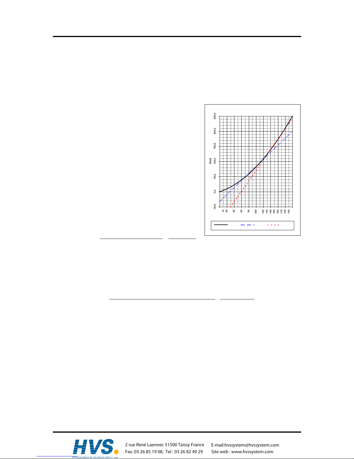
2.1.2. Speed Compensation using off-centre pressure, e.g. brake functions
The Speed Compensation of the CamCon Cam switch unit works using a linear function. If, for
example, the speed doubles, then the shift of the compensated cam changes and also moves forward
by twice the amount. If the ram on an eccentric press should be brought to a standstill at the exact
upper stop point, the brake action of the press under different speeds results in a quadratic function.
The Speed Compensation can therefore only find an approximation of the exact switch point for the
stopping of the press by adjusting the line of the cam lines to the brake curves in the working range of
the press.
In the graphic on the right the curved line represents the
brake point of the ram in relation to the speed.
U/min
Verlauf Nocke 1 Nocke 2
For the calculation of the parameters to be programmed
please proceed as follows:
- Define the working range (e.g. 20-50 rpm) and determine
two measuring points which have to be specified in the
working process (e.g. 30 and 40 rpm).
- Now let the machine run at 30 rpm and program or
optimise a cam without Speed Compensation so that, at
switch-OFF, the ram comes to a halt in top stop. Note the
switch-ON point of the cam (e.g. 340°).
- Now let the maching work with 40 rpm and program or
optimise one cam without Speed Compensation so that,
at switch-OFF, the ram comes to a halt in top stop. Once
again, note the switch-On point of the cam. (e.g. 332°).
- Now calculate the delay time, taking into account the
distance and speed difference, using this formula:
Delay time ( in sec. ) =
∆ way (in °) * 60 (sec./min.)
∆ Speed (in rpm.) * 360 (°/turn)
=
340-332 * 60
40-30 * 360
=
0.133 sec.
- The calculated delay time is now entered into the cam switch unit.
- Since the switch-OFF point has shifted through the entered Speed Compensation, the previously
programmed cam must be changed first. For the calculation of the exact switch-ON position, the
difference to the speed 0 rpm (here 30 rpm) must be added to the first measured switch-ON point
(first measuring point here 340°) The difference is calculated with the following formula:
∆ way (in °) =
delay time ( in sec. ) * ∆ Speed (in rpm.) * 360 (°/turn)
60 (sec./min.)
=
0.133 * 30 * 360
60
= 23.94°
- The switch-ON point of the cam has now shifted from 340° by approx. 24° to 364°.
As a result a cam with a switch-ON point of 4° and a speed compensation of 0.133 sec has been
calculated. This is entered in the cam switch unit as switch-OFF cam of the press.
Note: If the degree of accuracy is no longer sufficient when switch-OFF is done with one cam, two
or several outputs can be switched in parallel and the cam of those is then adjusted to the
required working range. For the calculation of two switch-OFF cams divide the working
range in 5 parts with 4 measuring points and then calculate the delay time value and the
cam value with the same formula as described above. For the calculation of the first cam,
use the measuring points 1 + 2 and for the calculation of the second cam use the
measuring point 3 + 4.
Through this association of the linear cam functions to the brake functions it is now possible to switch
OFF the cam via the entire working range of the press in the top stop.
,Version from: Aug. 04 Page: 12
2 rue René Laennec 51500 Taissy France
Fax: 03 26 85 19 08, Tel : 03 26 82 49 29
E-mail:hvssystem@hvssystem.com
Site web : www.hvssystem.com
Digitronic Digital Cam Switch Unit
Automationsanlagen GmbH CamCon DC50/51
2.1.3. Separate delay time for Speed Compensation of switch-ON and switch-OFF points
For CamCon devices of Software from 3/2002 Speed Compensation is now available for separate
switch-ON and switch-OFF points. This is necessary since some valves need longer to switch OFF
than to switch ON.
Switching attitude of a cam programs from 140° to 200° with 60 min-1.
Cam with 111ms Speed compensation for switch on point and 166ms
compensation for switch off point.
Cam with 111ms Speed compensation.
Cam without Speed compensation.
For the calculation of both delay times the same formuli are used as for a normal compensation. See
Chapter "2.1.1. Measuring delay time for Speed Compensation" on page 11 for entering delay time see
Chapter "7.3.3. Programming the delay time" on page 33.
Attention: If the switch-off-point of a Cam overtakes the switch on point at rising speed, the result will
be an non-defined signal.
2.2. Time - Cam
With nomale cam becomes with increasing plant speed switch-on time ever more briefly. If controlling
a glueing-station, the result would be an insufficent ammount of spreaded glue.
A Time - cam however has with each plant speed a firm temporal length, so that excactly the same
ammount of glue could be spread at changing speeds. The switch-on point of the Cam on a normal as
well as on a Time-Cam is appointed by a position-dependent Position value and a delay-time/speed
compensation.
Normal - cam Time - cam
60min-1
30min-1
60min-1
30min-1
For CamCon devices of software releases after 3/2002 Time Cam is also available for devices without
PLC - Logic - Module.
For entering a Time - Cam see Chapter "7.3.4. Programing Time-Cams" on page 34.
,Version from: Aug. 04 Page: 13
2 rue René Laennec 51500 Taissy France
Fax: 03 26 85 19 08, Tel : 03 26 82 49 29
E-mail:hvssystem@hvssystem.com
Site web : www.hvssystem.com
Digitronic Digital Cam Switch Unit
Automationsanlagen GmbH CamCon DC50/51
3. Installation
The unit is inserted into a cutout for front plate installation (see chapter "3.1. Dimensions" on page 14).
Connect the groundig pins on the back of the encasement as well as the cable cover to a grounding
point of the switchboard door in the shortest possible way. All cable connections must be done in a
cold state! The connection cables, e.g. for the measuring system or the serial interface, must be wired
with covers, and the covers have to grounded on both ends. Analog signals must also be wired with
covers, and the covers have to be grounded on one end.
3.1. Dimensions
DIGITRONIC
cutout as per
front door
can be locked
CamCon
plug input for encoder
attachment clip
Fig.: Drawing to aid the installation of CamCon
,Version from: Aug. 04 Page: 14
2 rue René Laennec 51500 Taissy France
Fax: 03 26 85 19 08, Tel : 03 26 82 49 29
E-mail:hvssystem@hvssystem.com
Site web : www.hvssystem.com
Digitronic Digital Cam Switch Unit
Automationsanlagen GmbH CamCon DC50/51
4. Electrical connections
4.1. Pin allocation of the CamCon
CamCon
Fig.: Backview of the CamCon with pin allocation
4.1.1. Pin allocation of the analog output
Pin 1: 0V signal mass for the analog output
Pin 2: Analog output 1
Pin 3: Analog output 2
4.1.2. Pin allocation of the SSI measuring system
Pin 11: 0V voltage supply for the SSI measuring system (encoder)
Pin 12: Data A or +
Pin 13: Data B or Pin 14: Clock A or +
Pin 15: Clock B or Pin 16: +24V DC voltage supply for the SSI measuring system (encoder)
,Version from: Aug. 04 Page: 15
2 rue René Laennec 51500 Taissy France
Fax: 03 26 85 19 08, Tel : 03 26 82 49 29
E-mail:hvssystem@hvssystem.com
Site web : www.hvssystem.com

Digitronic Digital Cam Switch Unit
Automationsanlagen GmbH CamCon DC50/51
4.1.3. Pin allocation of the incremental measuring system
Pin 11: 0V voltage supply for theincremental measuring system (encoder)
Pin 12: A Imp. (+)
Pin 13: A Imp. (-)
Pin 14: B Imp. (+)
Pin 15: B Imp. (-)
Pin 16: +24V DC voltage supply for the incremental measuring system (encoder)
Pin 17: C1 Imp. (+)
Pin 18: C1 Imp. (-)
Pin 19: C2 Imp. (+)
Pin 20: C2 Imp. (-)
4.1.4. Pin allocation of the inputs
Pin 21: 0V signal mass for inputs
Pin 22: Input 1
Pin 23: Input 2
Pin 24: Input 3
Pin 25: Input 4
Pin 26: Input 5
Pin 27: Input 6
Pin 28: Input 7
Pin 29: Input 8
Pin 30: +24V DC voltage supply for the outputs 1 to 16
Pin 31: 0V signal mass for inputs
Pin 32: Input 9
Pin 33: Input 10
Pin 34: Input 11
Pin 35: Input 12
Pin 36: Input 13
Pin 37: Input 14
Pin 38: Input 15
Pin 39: Input 16
Pin 40: +24V DC voltage supply for the outputs 1 to 16
4.1.5. Pin allocation of the outputs
Pin 41: 0V voltage supply for the outputs 1 to 16
Pin 42: Output 1
Pin 43: Output 2
Pin 44: Output 3
Pin 45: Output 4
Pin 46: Output 5
Pin 47: Output 6
Pin 48: Output 7
Pin 49: Output 8
Pin 50: +24V DC voltage supply for the outputs 1 to 16
Pin 51: 0V voltage supply for the outputs 1 to 16
Pin 52: Output 9
Pin 53: Output 10
Pin 54: Output 11
Pin 55: Output 12
Pin 56: Output 13
Pin 57: Output 14
Pin 58: Output 15
Pin 59: Output 16
Pin 60: +24V DC voltage supply for outputs 1 to 16
,Version from: Aug. 04 Page: 16
2 rue René Laennec 51500 Taissy France
Fax: 03 26 85 19 08, Tel : 03 26 82 49 29
E-mail:hvssystem@hvssystem.com
Site web : www.hvssystem.com

Digitronic Digital Cam Switch Unit
Automationsanlagen GmbH CamCon DC50/51
Pin 61: 0V voltage supply for the outputs 17 to 32
Pin 62: Output 17
Pin 63: Output 18
Pin 64: Output 19
Pin 65: Output 20
Pin 66: Output 21
Pin 67: Output 22
Pin 68: Output 23
Pin 69: Output 24
Pin 70: +24V DC voltage supply for the outputs 17 to 32
Pin 71: 0V voltage supply for the outputs 17 to 32
Pin 72: Output 25
Pin 73: Output 26
Pin 74: Output 27
Pin 75: Output 28
Pin 76: Output 29
Pin 77: Output 30
Pin 78: Output 31
Pin 79: Output 32
Pin 80: +24V DC voltage supply for the outputs 17 to 32
4.1.6. Pin allocation of the voltage supply
Pin 81: 0V voltage supply for the CPU
Pin 82: 0V voltage supply for the CPU
Pin 83: +24V DC voltage supply for the CPU
Pin 84: +24V DC voltage supply for the CPU
Attention : Pins 30, 40, 50 and 60 are connected to each other.
Pins 1, 11, 21, 31, 41, 51, 61, 71, 81 and 82 are connected to each other.
4.1.7. Pin allocation of the serial interface
When you order the CamCon you can choose the type of the serial interfaec between RS232 or
RS485. Wiring and connector allocation are different for each type of the serial interface.
4.1.7.1. Pin allocation of the serial RS232 interface
DSUB 9 pinboard: RS232 Interface for PC attachment (max. 15m cable length)
Pin 1,4 Do not connect !
Pin 2 TXD
Pin 3 RXD
Pin 5 Mass
Pin 6-9 N.C.
,Version from: Aug. 04 Page: 17
2 rue René Laennec 51500 Taissy France
Fax: 03 26 85 19 08, Tel : 03 26 82 49 29
E-mail:hvssystem@hvssystem.com
Site web : www.hvssystem.com
Digitronic Digital Cam Switch Unit
Automationsanlagen GmbH CamCon DC50/51
4.1.7.2. Pin allocation of the serial RS485 interface
DSUB 9 pinboard: RS485 Interface for PC attachment or for the networking of many devices
(max. 1000m cable length).
Pin 1,4 Closedown resistors for RS485
Pin 2 B (-)
Pin 3 A (+)
Pin 5 GND
Pin 6-9 N.C.
Interface converterCamCon
CamCon
CamCon
CamCon
CamCon
Interface converter PC
PC
Note: The pins 1 and 2, as well as the pins 3 and 4 have to be bridged in the
attachment plug of the first and last device in a networked chain at the RS485
Interface, to close the data and reception line perfectly. Corresponding
closedown resistors are attached to the system at pin 1 and 4.
,Version from: Aug. 04 Page: 18
2 rue René Laennec 51500 Taissy France
Fax: 03 26 85 19 08, Tel : 03 26 82 49 29
E-mail:hvssystem@hvssystem.com
Site web : www.hvssystem.com
Digitronic Digital Cam Switch Unit
Automationsanlagen GmbH CamCon DC50/51
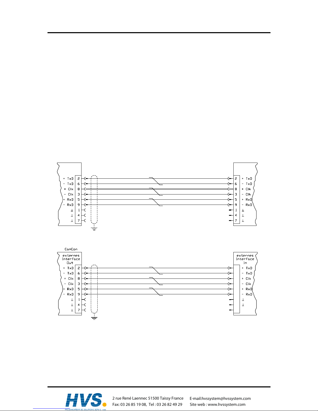
4.1.8. Pin allocation of the external interface
If you ordered the external interface along with the CamCon, you have the possibility to extend your
CamCon by a CamCon DC91/IO, DC92/I or DC16/IO. The extensions are clipped on to a rail in the
clipboard. They are connected with a cable with 6 poles, type "KK91/IO-XX" with the 9pole D-Sub male
plug "external Inter in" at the CamCon module (maximum cable length is 300m). The data transfer is
done through optical couplers, so that the connection remains potential free.
For the CamCon DC16/IO a DSUB cable with flatwire adapter can be ordered, order No. "KK50-16/IOXX" (Note: XX refers to the cables length in meters).
DSUB 9 socket: link of external in - and output modules e.g. DC91
Pin 1,4,7 GND
Pin 2 TxD +
Pin 6 TxD Pin 8 CLK +
Pin 3 CLK Pin 5 RxD +
Pin 9 RxD -
Connection cable CamCon DC91/IO
external
interface
OUT
CamCon CamCon DC 91
IN
external
interface
Connection cable CamCon DC91/IO
CamCon DC16/IO
2
3
5
6
8
9
4
7
1,10
Stift
,Version from: Aug. 04 Page: 19
2 rue René Laennec 51500 Taissy France
Fax: 03 26 85 19 08, Tel : 03 26 82 49 29
E-mail:hvssystem@hvssystem.com
Site web : www.hvssystem.com
Digitronic Digital Cam Switch Unit
Automationsanlagen GmbH CamCon DC50/51
4.2. The measuring system
The measuring system is designed to record the necessary actual values (positions) for the Cam
Switch Unit. Many different measuring system can be linked with the CamCon.
See chapter "4.1. Pin allocation" on page 15 and for adjustment of the measuring system to the
software of the CamCons please also consult Chapter "7.4.1. Measuring system" on page 45.
Note: Please also consult the instruction manual for your measuring system.
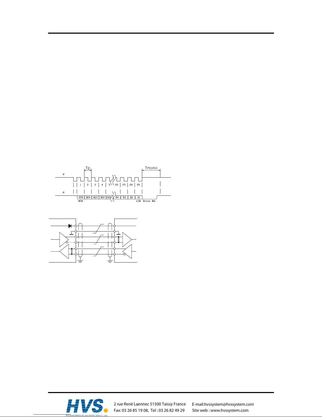
4.2.1. SSI Measuring system input
Systems with a synchronous series interface = SSI. The SSI interface is widely used in industry for
absolute single and multi-turn angle encoder. At this interface the CamCon supplies the measuring
system with 24Volt. For the purpose of data reading the CamCon sends a stroke signal (clock) with
RS422 level to the measuring system. This answers synchronously with the data output of the position
in the grey code. The frequency of the pulse signal depends on the length of the cable to the
measuring system and can be set in the CamCon.
Note: The data record corresponds to the Stegmann SSI Standard!
Clock
Data
Tp = clock impulse
max. 1MHz to min. 66kHz.
(adjustable through the cable
length)
Tmono = Mono flop time 25µs
CamCon
Encoder
+24V DC
0V
Clock +
Clock Data +
Data -
Please note:
Use a screened dual strand connection cable. Do not place
the cable parallel to a high voltage cable. If possible, lay the
screening down on both sides.
4.2.2. Parallel measuring system input
Systems with parallel 24V data leads, e.g. single turn - angle encoder or via a transformer with parallel
data output.
In this instance a gray or binary encoded value is attached to the free inputs of the CamCon and this
will be read as actual value. Since the connection cable are quite expensive and the EMV compatibility is limited, this interface type is rarely used in industry nowadays.
Note: Since the outputs are partly switched parallel to the inputs in CamCon DC16, DC115,
DC300 and CamCon 1756-DICAM, these must not be programmed under any
circumstances and this reduces the number of available outputs.
Warning: Reading a binary encoded value into the CamCon is only permitted after consultation with
the Service department of the company Digitronic.
,Version from: Aug. 04 Page: 20
2 rue René Laennec 51500 Taissy France
Fax: 03 26 85 19 08, Tel : 03 26 82 49 29
E-mail:hvssystem@hvssystem.com
Site web : www.hvssystem.com
Digitronic Digital Cam Switch Unit
Automationsanlagen GmbH CamCon DC50/51
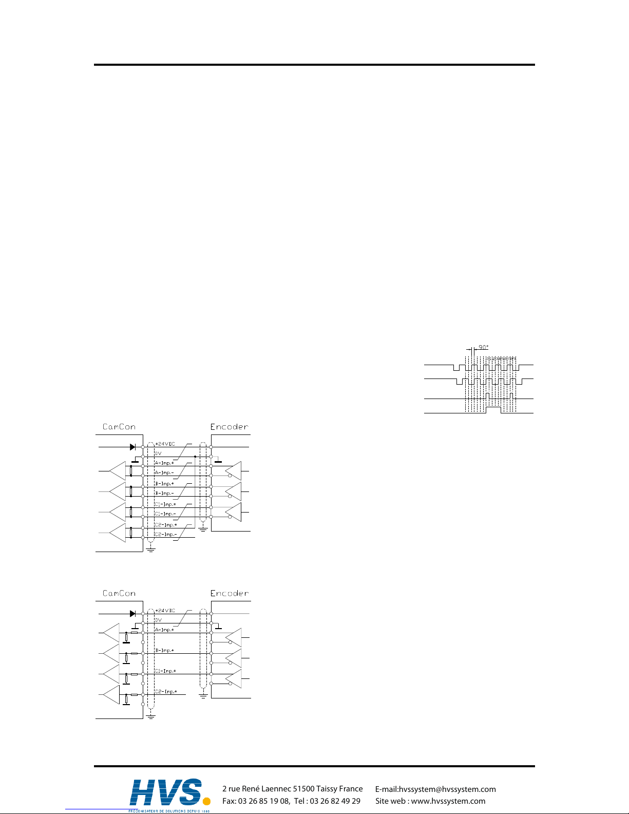
4.2.3. Incremental measuring system input
Systems with 90° phase shift signals such as turning angle encoders, glass measuring rods or flow
measuring devices.
At the present time incremental measuring inputs for the CamCon DC16/50/51/115/300 and DC1756
are available as an option. We differentiate between three signal levels:
- 24V PNP Signal inputs (Order number Option: J)
- 5V RS422 Signal inputs (Order number Option: I)
- Hiperface Signal inputs (Order number Option: H)
Note: For the CamCon DC16 and DC300 only the version with 24V PNP signal is available. For
the CamCon 1756-DICAM the version with 24V PNP signal and Hiperface Signal is
available. If a different signal level is necessary, this can be converted externally with the
INCDRV converter.
In all cases the CamCon supplies the measuring system with 24Volt/DC or in CamCon DC115
optionally with 5 or 24Volt/DC. As a counting signal the measuring system gives out two impulses at a
time shifted by 90° (A + B). These are counted in the CamCon and are evaluated as position values. In
addition, for each rotation another zero impulse (Clear 1) is given out for synchronisation purposes. In
order to stop synchronisation (zero setting) of the counter, a further clear signal (Clear 2) is available
on the CamCon.
The signals Clear 1 and Clear 2 are to standard AND linked and can be
changed in their function with the software. See Chapter "7.4.1.6.3.
Incremental - measuring system" on page 49
Clear 1
Clear 2
B Imp.
A Imp.
4.2.3.1. Incremental measuring system input with 5V RS422 level
If the 5V RS422 system is used, all signals of the measuring
system input must be active, otherwise the input conditions are
undefined. If no signal is available for one of the two Clear
inputs, then this input must be switched to mass on the (+)
signal in order to switch the input to low. The inputs of the
measuring system can be activated with a maximum voltage of
5V. Please pay attention to the power supply of the angle
encoder which can be 5Volt as well as 24Volt. Only the CamCon
DC115 can at present provide a voltage of 5Volt for the supply of
the angle encoder.
4.2.3.2. Incremental measuring system input with 24V PNP level
If a 24V PNP signal is used for data input, then only the (+)
signals of the inputs may be connected. The (-) signals must
stay inactive in this case. The connection of such a measuring
system requires a change of the interal switch system and must
therefore be stated on the order form.
Note: At the incremental input of the CamCon DC16,
DC300 and DC1756 no (-) signals are available.
,Version from: Aug. 04 Page: 21
2 rue René Laennec 51500 Taissy France
Fax: 03 26 85 19 08, Tel : 03 26 82 49 29
E-mail:hvssystem@hvssystem.com
Site web : www.hvssystem.com
Digitronic Digital Cam Switch Unit
Automationsanlagen GmbH CamCon DC50/51
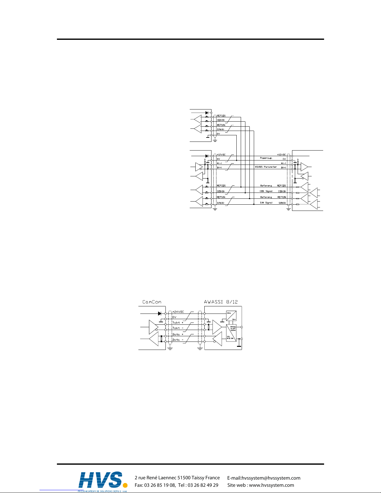
4.2.3.3. Incremental Hiperface measuring system input with SINCOS level
The Hiperface measuring system is a feedback system for servo-motors of the company Stegmann.
It is a mixed system and consists of an absolute measuring system and an incremental measuring
system. The absolute measuring system sends its values via RS485 interface to the counter. The
incremental measuring system works with analog sine - and cosine interface with a resolution of 512 or
1024 impulses per revolution.
The CamCon with the Hiperface signal input
(option: H) reads only the incremental sine - and
cosine signal. The signals are converted and
counted in the CamCon into normal incremental
measuring system signals.
controller SINCOS
CamCon
Since the absolute measuring system of the
Hiperface interface is not used and no clear signals are available, the CamCon must be
initialized after each restart.
This must be done by the preset input of the
CamCon. See for this to chapter 7.4.2.4. Actual
position preset on page 56.
Note: The maximum number of
revolutions per minute is 3000 min
-1
with 512 Impulse per revolution.
The maximum number of revolutions per minute is 1500 min
-1
with 1024 Impulse per
revolution.
4.2.4. Analog measuring system input
These are systems which receive their actual value through conversion of current or voltage signal,
such as temperature or pressure sensors.
For the recording of analog signals the analog to SSI conversion module AWA/SSI in 8 and 12 bit
resolution is available for the CamCon. This module is connected to the SSI of the CamCon and is
switched ON through the selection of the analog measuring system in the menu ”Measuring system”.
,Version from: Aug. 04 Page: 22
2 rue René Laennec 51500 Taissy France
Fax: 03 26 85 19 08, Tel : 03 26 82 49 29
E-mail:hvssystem@hvssystem.com
Site web : www.hvssystem.com
Digitronic Digital Cam Switch Unit
Automationsanlagen GmbH CamCon DC50/51
4.2.5. PLL measuring system input
Systems with Phase - Lock - Loop data recording. In these systems the actual value is found through
interpolation of initiator impulses. This measuring system is applied to machines with constant speed
and with a cyclic pulse.
= Initiator impulse
= Found actual value
The Initiator can be connected to any free input of the CamCon.
Note: For CamCon DC115 a special input is available on the 25pol. SUB-D plug.
See also chapter "7.4.1.6.5. PLL measuring system" on page 51.
4.2.6. Timer as a measuring system
Systems which are controlled by elapsed time. In this case the CamCon makes a time available with a
time basis of minimum 1 ms as actual value. Through laying on of input signals it is possible to
influence the elapsed time. This measuring system is applied to machines with a fixed time scanner as
a control feature, e.g. washing machines.
See also chapter "7.4.1.6.6. Timer way simulation" on page 51.
4.2.7. RS232 as a measuring system
Systems, receiving their actual position through the RS232 interface, e.g. for a junction of a Stegmann
POMUX linear scale to a RS232 data output.
Warning The activation of this measuring system blocks the RS232 interface for
programming. This measuring system is only reasonable with a CamCon
DC50/51.
,Version from: Aug. 04 Page: 23
2 rue René Laennec 51500 Taissy France
Fax: 03 26 85 19 08, Tel : 03 26 82 49 29
E-mail:hvssystem@hvssystem.com
Site web : www.hvssystem.com

Digitronic Digital Cam Switch Unit
Automationsanlagen GmbH CamCon DC50/51
4.3. The outputs
The CamCon has, concerning each upgrading level, up to 32 outputs and with extreme extension (e.g.
CamCon DC16/IO, DAC16 or DC91/IO) up to 200 short circuit-proof outputs. They deliver 24Volt high
active signals and are not potentially free towards the CPU. The outputs 1 to 16, as well as 17 to 32 of
the unit have to be supplied with 24Volt , because the power supply of the outputs has been separated
in order to achieve a better power distribution.
4.3.1. The 40mA outputs (only CamCon device with aluminium back wall)
If all outputs are activated, not more than 40 mA permanent current in the complete temperature range
should be extracted per output, else the unit will deactivate with an error message. If a higher starting
performance is required, one has to know that the outputs are combined in 4 groups, each group
consisting of 8 outputs. Within each group, 480 mA permanent current at a surrounding temperature of
50°C, and at a surrounding temperature of 25°C even 700mA permanent current is available. This
permanent current can be dirtributed freely within a group, as long as the single output current of 300
mA is not overshot (see chapter "7.4.6.2. Setting the outputs" on page 63).
4.3.2. The 500mA outputs
At a surrounding temperature of 25°C even 500mA permanent current is available for each output. If
your outputs are overloaded or short-circuited the unit will deactivate with an "out-err" message
(see chapter "7.4.6.2. Setting the outputs" on page 63).
Attention: For inductive loads the inductances have to be tripped with a freewheeling
diode.
4.4. The inputs
The CamCon has, concerning each upgrading level, up to 16 inputs and with extreme extension up to
200 inputs. These inputs work with high externally active 24Volt signals and are not potentially free
towards the CPU.
The input wiring:
The input resistance
is about 5.7 KOhm.
The inputs of the CamCon have not been covered with functions by the factory. The user would have
to do this himself in the process of setting system data of the CamCon depending on his requirements.
See chapter "7.4.6. System upgrading" on page 63, chapter "7.4.1. Measuring system" on page 45,
chapter "7.4.6.7. Setting the external program selection" on page 64 and chapter "7.4.6.4. Setting the
keyboard lock" on page 63.
4.5. Precautionary measures for welding work
Attention: For the duration of welding operations carried out at the machine, the
connecting wires concerning the data exchange from the measuring system to
the CamCon and the power supply as well as the grounding connections and
inputs and outputs have to be separated from the CamCon.
,Version from: Aug. 04 Page: 24
2 rue René Laennec 51500 Taissy France
Fax: 03 26 85 19 08, Tel : 03 26 82 49 29
E-mail:hvssystem@hvssystem.com
Site web : www.hvssystem.com
Digitronic Digital Cam Switch Unit
Automationsanlagen GmbH CamCon DC50/51
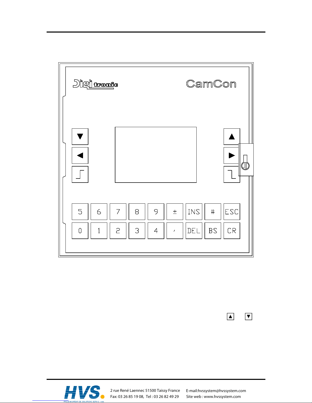
5. Outline of the operator terminal
5.1. Frontview CamCon
5.2. The liquid crystal display (LCD)
The display unit of the CamCon 50 contains a graphical LCD with 128x64 picture elements. For the
visual user prompting, all menus concerning the programming of the unit, state and error messages of
the outputs, as well as the current position and speed, are represented here. The contrast can be
adjusted to the current surrounding temperature with the keyboard.
5.3. Contrast setting
You can increase or decrease the contrast of the LCD in this display mode with the and keys.
Keeping these keys pressed continues the change of contrast.
5.4. The keyboard
The plastic foil keyboard of the CamCon is non-sensitive towards dirt and is solvent resisting. The keys
have a noticable action point for the tactile feedback, as well as an acoustic input acknowledgement
(see chapter 7.4.6.4.7.4.6.4. Setting the keyboard lock on page 63).
,Version from: Aug. 04 Page: 25
2 rue René Laennec 51500 Taissy France
Fax: 03 26 85 19 08, Tel : 03 26 82 49 29
E-mail:hvssystem@hvssystem.com
Site web : www.hvssystem.com
Digitronic Digital Cam Switch Unit
Automationsanlagen GmbH CamCon DC50/51
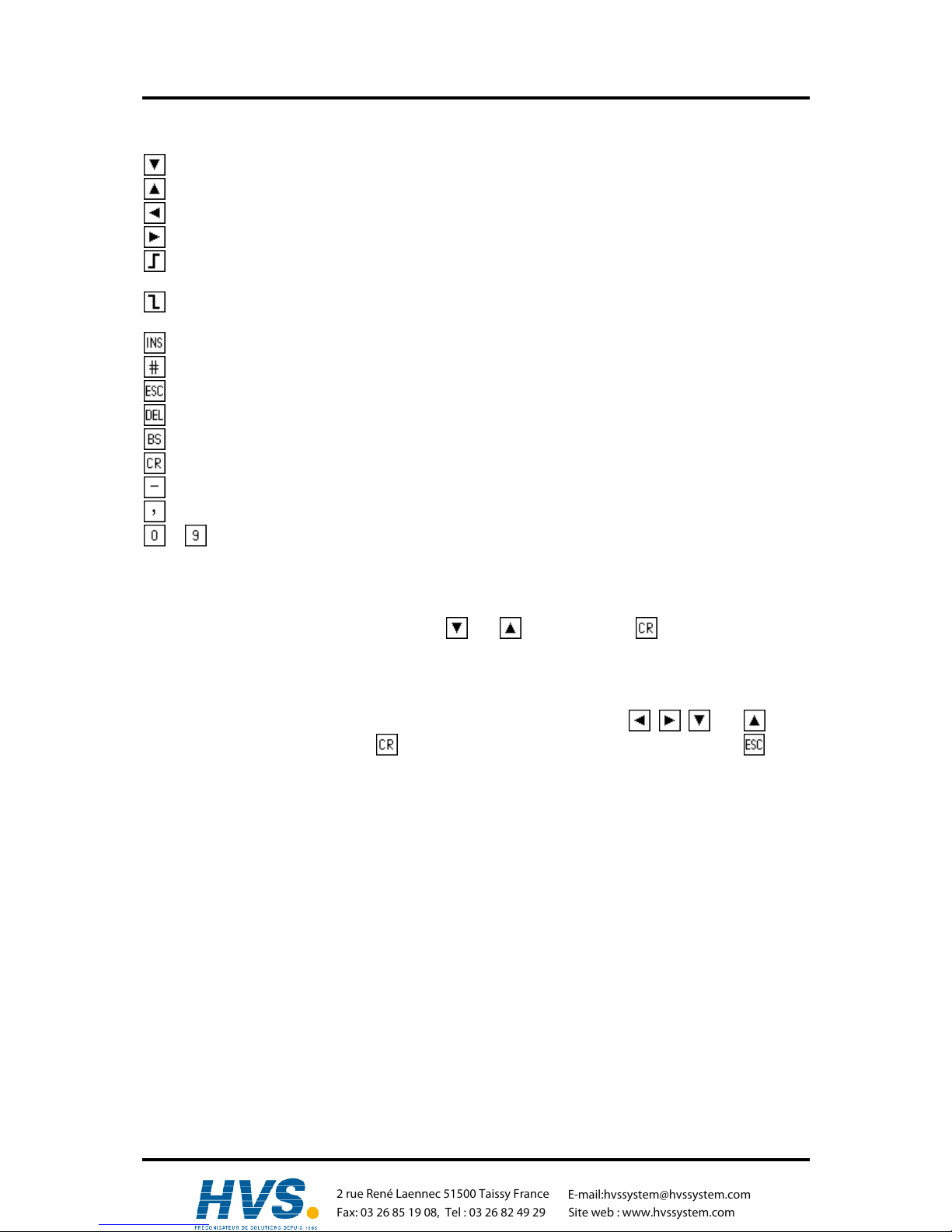
5.5. Outline of key functions
cursor down
cursor up
cursor to the left, shifting cams
cursor to the right, shifting cams
choose cam activation point, character selection during text input,
(or PC 'PageUp' key)
choose cam deactivation point, character selection during text input
(or PC 'PageDown' key)
input of cams, special measuring systems, character during text input
place holder for display formats, reset during error messages, special functions
Escape: leaving the current menu, returning to the next higher menu
deletion of cams, outputs, programs and single characters during text input
deletion of single characters during text input
confirm input and save data
changes the algebraic sign during data input
comma
... numeric keys for data input
5.6. Menu selection
You can select a desired menu by pressing the corresponding numeric key or by moving the cursor
(the black beam) on the menu name with keys and and pressing the key.
5.7. Selection of a menu point
The input in the single menus issubdevided into menu points. These are active (or selected), if the
display is inverted. The selection of these menu points is made with keys , , and and a
confirmation of your choice with the key. You can always cancel an input by pressing the key. If
you pressed a wrong key, the unit shows a hint of the keys you can use in this menu and their
functions.
,Version from: Aug. 04 Page: 26
2 rue René Laennec 51500 Taissy France
Fax: 03 26 85 19 08, Tel : 03 26 82 49 29
E-mail:hvssystem@hvssystem.com
Site web : www.hvssystem.com

Digitronic Digital Cam Switch Unit
Automationsanlagen GmbH CamCon DC50/51
5.8. Text input
With menu points, in which texts have to be implemented, the and keys function together with
the and keys like a coordinate control. You select the desired position for the first character,
using the and keys. Then you can choose the character with the and keys, by going up
and down through the alphabet or the ASCII characters. If you move the cursor to the right with the
key, character entered prior to this will appear in the new position of the cursor, simplifying making
repeated inputs of the same character.
If you have made an error you can go back to the wrong character to correct it, using the key or the
key. This will cause the other characters to become erased. To abandon the input press the
key.
Attention: The software for the text input at the CamCon has changed since EPROMS of 1/97. The
selection of desired characters is now realized with keys and . With keys and
you can now position the cursor anywhere in the previously entered text. You can
overwrite characters, insert characters by pressing the key or delete characters with
keys or .
Note: The text input is also possible directly via PC.
,Version from: Aug. 04 Page: 27
2 rue René Laennec 51500 Taissy France
Fax: 03 26 85 19 08, Tel : 03 26 82 49 29
E-mail:hvssystem@hvssystem.com
Site web : www.hvssystem.com
 Loading...