

Digitronic CamCon DC33/X Instruction Manual
Digital Cam Switch Unit
CamCon DC33/X
with 8 programs
Digitronic Automationsanlagen GmbH
Steinbeisstraße 3 • D - 72636 Frickenhausen • Tel. +49 7022 40590-0 • Fax -10
Auf der Langwies 1 • D - 65510 Hünstetten-Wallbach • Tel. +49 6126 9453-0 • Fax -42
Internet: http://www.digitronic.com • E-Mail: mail@digitronic.com

Digitronic Digital Cam Switch Unit
Automationsanlagen GmbH CamCon DC33/X with 8 programs
For your attention
This instruction manual relates to the CamCon DC33/X from Nov. 1996. The company Digitronic
Automationsanlagen GmbH reserves the right to make changes which present an improvement of the
quality or functionality of the device without prior notice. The instruction manual was created with great
care, although it may not be error-proof. We would be grateful for any communication relating to any
errors you may have found.
Update
You can also obtain this instruction manual on the Internet at http://www.digitronic.com in the latest
version as PDF file.
Qualified personnel
This device may only be started and operated by qualified staff. By qualified we mean personnel who
are entitled to handle, to earth and to lable devices, systems and power circuits in accordance with the
technology safety standards.
Liability
(1) The supplier is liable for damages caused by himself or by the owner of the rights up to the sum of
the sales price. He is not liable for loss of profits, forfeited savings, intermediate and successive
damages.
(2) The above mentioned limits to liability do not apply to insurance of named characteristics and
damages which were caused deliberately or through negligence.
Protection
The CamCon DC33/X and this instruction manual are protected by copyright. All rights are reserved.
Neither the CamCon DC33/X, nor this document may be copied as a whole or partially, photocopied,
reproduced, translated or transferred to electronic media of any kind or into machine readable format
without prior written permission by the company Digitronic Automationsanlagen GmbH.
Note: We have examined the devices of the CamCon series for year 2000 compatibility and
have not found any adverse effects on any functions.
Note: CamCon is a registered trademark of the company Firma Digitronic
Automationsanlagen GmbH.
Note: The devices of the CamCon series comply with the standards for electromagnetic
compatibility: EN 55011, EN 55022, EN 55024 Part 2, EN 50082 Part 2, ENV 50140,
VDE 0843 Part 2, VDE 0843 Part 4, VDE 0871, VDE 0875 Part 3 ("N"),
VDE 0875 Part 11, VDE 0877 Part 2, IEC 801 Part 3, IEC 801 Part 2, IEC 801 Part 4,
IEC 801 Part 5.
(c) Copyright 1992 - 2009 / File: DC33X_E.DOC
Digitronic Automationsanlagen GmbH
Auf der Langwies 1
D-65510 Hünstetten - Wallbach
Tel. (+49)6126/9453-0 Fax. (+49)6126/9453-42
Internet: http://www.digitronic.com
E-Mail: mail@digitronic.com
Version from: 18.06.2009 Page: 2

Digitronic Digital Cam Switch Unit
Automationsanlagen GmbH CamCon DC33/X with 8 programs
TABLE OF CONTENTS
1. Introduction..........................................................................................................................................5
2. Operating Pinciples..............................................................................................................................6
2.1. Speed Compensation.......................................................................................................................7
2.1.1. Measuring delay time for Speed Compensation............................................................................9
2.1.1.1. Measuring delay time through actual differences.......................................................................9
2.1.1.2. Measuring delay time by means of different measuring points...................................................9
3. Installation..........................................................................................................................................10
3.1. Dimensions.....................................................................................................................................10
4. Electrical connections........................................................................................................................11
4.1. Pin allocation CamCon with 16 outputs and 8 programs................................................................11
4.2. The encoder....................................................................................................................................12
4.3. The outputs.....................................................................................................................................12
4.4. External program selection.............................................................................................................12
4.5. External activation of the keyboard lock.........................................................................................12
4.6. Precautions to be taken at welding operations...............................................................................12
5. Outline of the operator terminal.........................................................................................................13
5.1. Frontview CamCon.........................................................................................................................13
5.2. The output display...........................................................................................................................13
5.3. The seven-segment display............................................................................................................13
5.4. The keyboard..................................................................................................................................13
5.4.1. Display of position and speed......................................................................................................13
6. Commissioning..................................................................................................................................14
6.1. Complete deletion...........................................................................................................................14
6.2. Initialization.....................................................................................................................................14
6.2.1. User keys for the system registers..............................................................................................14
6.2.2. The encoder resolution................................................................................................................15
6.2.3. The F/R change over...................................................................................................................15
6.2.4. The zero point correction.............................................................................................................15
6.2.5. Setting of the programming mode...............................................................................................15
6.3. The dead time compensation.........................................................................................................15
6.4. Cam programming in programming mode "0"................................................................................16
6.4.1. Selecting a program.....................................................................................................................16
6.4.2. Selecting an output......................................................................................................................16
6.4.3. Searching for cams......................................................................................................................16
6.4.4. Setting the preset value...............................................................................................................16
6.4.5. Shifting the activation point..........................................................................................................16
6.4.6. Shifting the deactivation point......................................................................................................17
6.4.7. Leaving cam programming..........................................................................................................17
6.4.8. Examples for cam programming in the programming mode "0"..................................................18
6.4.8.1. Programming the first cam.......................................................................................................18
6.4.8.2. Programming additional cams on an output.............................................................................19
6.4.8.3. Deletion of a particular cam......................................................................................................20
6.5. Cam programming in programming mode "1"................................................................................21
6.5.1. Selecting a program.....................................................................................................................21
6.5.2. Selecting an output......................................................................................................................21
6.5.3. Shifting the activation point..........................................................................................................21
6.5.4. Shifting the deactivation point......................................................................................................21
6.5.5. Leaving cam programming..........................................................................................................22
Version from: 18.06.2009 Page: 3

Digitronic Digital Cam Switch Unit
Automationsanlagen GmbH CamCon DC33/X with 8 programs
6.5.6. Examples for cam programming in the programming mode "1"..................................................22
6.5.6.1. Cam programming....................................................................................................................22
6.5.6.2. Deletion of cams.......................................................................................................................22
7. Outline of operations..........................................................................................................................23
7.1. Switching the standard display........................................................................................................23
7.2. Programming the system constants...............................................................................................23
7.3. Dead time programming.................................................................................................................23
7.4. Cam programming..........................................................................................................................23
8. watch doc...........................................................................................................................................24
9. Troubleshooting.................................................................................................................................24
10. Technical data of the CamCon........................................................................................................25
11. Keyword table..................................................................................................................................26
Version from: 18.06.2009 Page: 4

Digitronic Digital Cam Switch Unit
Automationsanlagen GmbH CamCon DC33/X with 8 programs
1. Introduction
Electronic Cam Switch Units have been successfully used in industry for a long time. Experiences
collected in close liaison with users over the years have been included in the development of the
CamCon series. The result is a compact digital cam switch unit which is user friendly and reliable to a
high degree. The following characteristics testify the excellence of the CamCon:
* Tested and reliable hardware
* Short-circuit-proof outputs
* Graphic liquid crystal display with 128x64 pixels in the CamCon DC50,51.
* Large and clearly visible 7-Segment display for program, position and speed on
CamCon DC30,33 and 40.
* Any number of cams per output can be programmed.
* Up to 32000 Programs for product administration
* Master, for example: machine cams
* Optimising switch points when machine is in operation
* Compensation of mechanical delay time of switch components for switch-ON and switch-OFF
points can be set in steps of 100µs separately (DTC = delay time or Speed Compensation).
* Not linear Speed Compensation (NLT).
* Position - Triggert - Time - Cams
* Power supply 24V DC +/- 20%
* Mounting of suspension rails to EN 50022 on CamCon DC16 and 90
* Switchboard panel standard casing 144 x 144 x 63mm to DIN 43700 on CamCon DC33,40 and 51
* S5 Components group for S5 115U, 135U and 155U on CamCon DC115
* S7 Components group for S7 300 on CamCon DC300
* AB Components group for ControlLogix 1756 on CamCon 1756-DICAM
* S5 Switch-ON via PG interface with L1 - Bus on CamCon DC16,40,50,51 and 90
* PLC Logic Module (optional)
* Shift register (optional)
* OP - Functions
* Analog outputs (optional)
Cam switch units are used wherever switching operations are periodically repeated. Digital cam switch
units are an optimum replacement of mechanical units and offer in addition many other advantages,
such as:
* Simplification of mounting and adjustment operations
* Repeatable adjustment facility
* Standardised for almost all areas of application
* Reliability
* High switch speed
* Speed Compensation
* Product administration for quick format change
Version from: 18.06.2009 Page: 5
Digitronic Digital Cam Switch Unit
Automationsanlagen GmbH CamCon DC33/X with 8 programs
2. Operating Pinciples
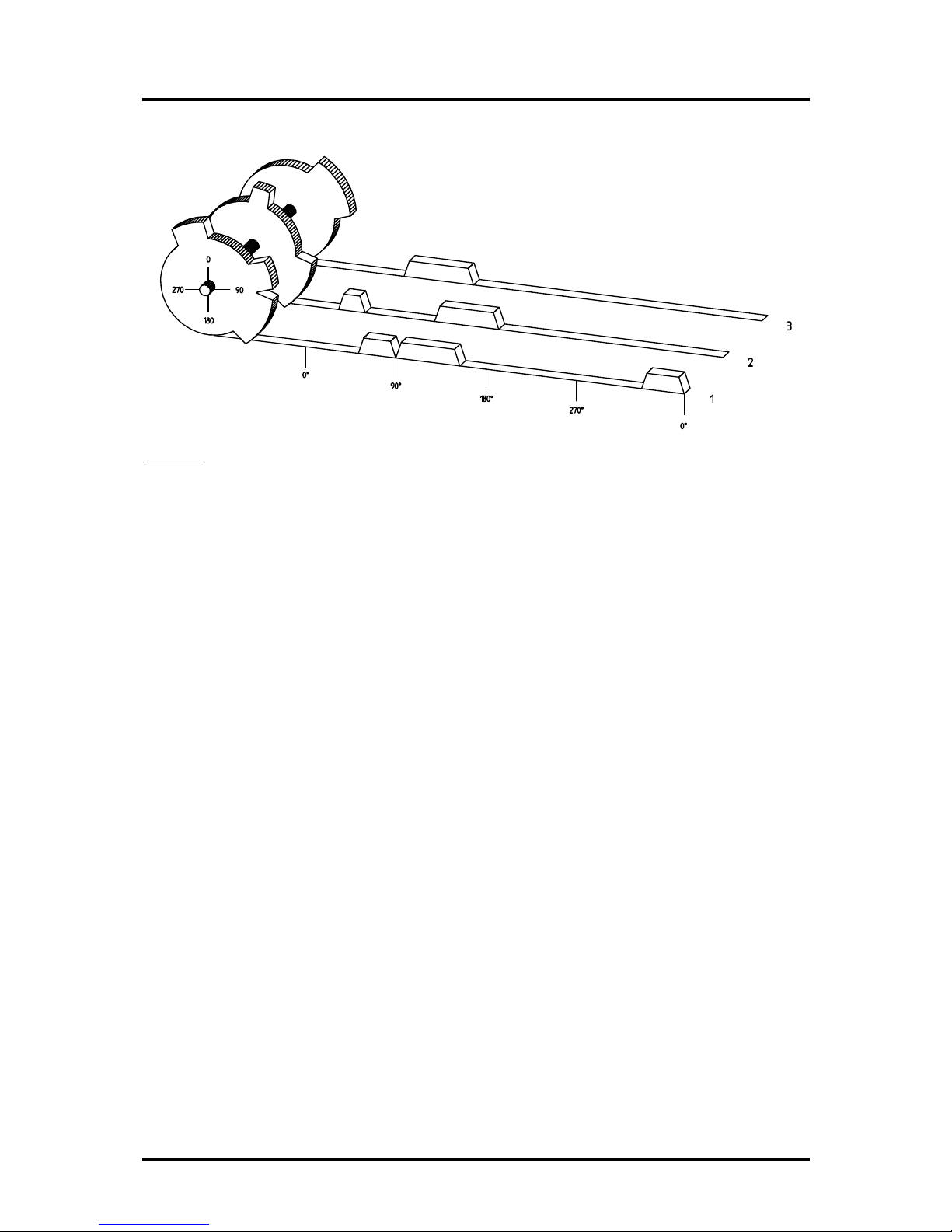
Diagram: Principles of a Cam Switch Unit
A principle for better comprehension of the function of a Cam Switch Unit is here presented. It has 3
outputs with the following cams:
Output 1: Cam 1: Switch-ON position60° Switch-OFF position 85°
Cam 2: Switch-ON position95° Switch-OFF position 145°
Cam 3: Switch-ON position325° Switch-OFF position 355°
Output 2: Cam 1: Switch-ON position5° Switch-OFF position 20°
Cam 2: Switch-ON position95° Switch-OFF position 145°
Output 3: Cam 1: Switch-ON position30° Switch-OFF position 85°
The positions of the output signals, here presented as three tracks, occur when the three cam disks
turn anti-clockwise past a sensor, which scans the cams on the 0°-axis.
In a mechanical cam switch unit, the switch interval, i.e. the range between switch-ON and switch-OFF
position are determined by the length of the cam. The length and the position of the cam can only be
varied marginally and this is mechanically highly demanding and time consuming. With CamCon such
adjustments can be realised in a fraction of time; in addition, there can be any number of tracks. A
measuring system which is fitted to the device reports the position to the CamCon. The CamCon
compares it with the programmed switch-ON and Switch-OFF positions of all outputs. If the position
lies in the range of a programmed switch-ON / switch-OFF position (cam), then the respective outputs
are active.
Version from: 18.06.2009 Page: 6
Digitronic Digital Cam Switch Unit
Automationsanlagen GmbH CamCon DC33/X with 8 programs
2.1. Speed Compensation
Each mechanical switch component (e.g. shield, magnetic valve) has a delay time, i.e. the time
between the start signal and the actual switching of the contacts. In processes where positioning is
executed on a moving system, this can cause problems. If such a process is driven with different
speeds, different positions are caused. To avoid this happening, new timings for the switch signals of
each speed would have to be calculated.
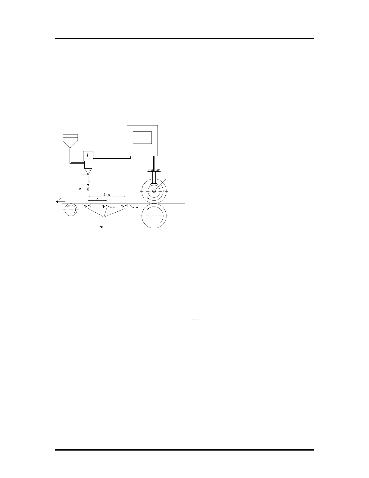
In order to ilustrate the complicated issues surrounding delay time or speed compensation, this will be
shown on the example of a packaging machine. In the process shown in the diagram, a glue point has
to be placed in an exactly defined spot on a moving paper track.
magnetic valve
glue nozzle
drop
paper
Points where the glue
hits the paper at the
different speeds .
paper track
encoder
CamCon
The system has the following parameters:
v
p
- Speed of the paper track
v
T
- Falling speed of the drop of glue
d - Distance between the glue nozzle and
the paper track
T
MV
- Delay time of the magnetic valve
Without speed compensation the following would happen:
As soon as the measuring system has reached a certain position, the CamCon sends a signal to the
magnetic valve. The glue nozzle opens for a short time during which a drop of glue ejects. Between the
start of the impulse and the exit of the drop time passes, which is mainly caused by the delay time of
the magnetic valve T
MV.
. A further delay is caused by the time which the droplet needs to pass the
distance between the glue nozzle and the surface of the paper.
This flight time is calculated as follows:
t
Flight
=
d
v
T
In total there the delay time is tFlight+T
MV.
During this time the paper track moves on by a specific
distance x.
It would now be possible to move the position, where the magnetic valve is switched on, forward by a
specific amount, so that the glue droplet hits the same spot again as during standstill. In this way a
speed compensation is created which works only at a specific speed of the paper. As soon as the
speed of the device and consequently that of the paper track is, for example, doubled, the hit point of
the glue droplet is shifted by the distance x, so that, without any speed compensation, it would move
backward by double the distance (2 ⋅ x) in total.
The automatic speed compensation of the CamCon makes it now possible to drive processes with
variable speed; CamCon registers the speed of the device continuously and adjusts the cams which
determine the switch time points "On Line" depending on the speed. This has the effect that the
outputs for the switch components are switched ON or OFF earlier. The direction of the movement is
of no significance in this instance.
Version from: 18.06.2009 Page: 7

Digitronic Digital Cam Switch Unit
Automationsanlagen GmbH CamCon DC33/X with 8 programs
A small example in figures was designed to eludicate:
Supposing the drive cylinder with the measuring system has a circumference of 360mm, so that one
millimeter of the circumference corresponds to exactly one angle degree of the measuring system.
The device has the following parameters:
v
droplet
= 20m/s
d = 20cm
T
MV
= 20ms
This results in the following flight time of the droplet:
tFlight=
d
v
T
=
0,2m
20m/s
= 10ms
The total delay time is then Tdead
, altogether
= TMV + tFlight = 20ms + 10ms = 30ms
During this time the paper track moves on by the distance x = v
paper
⋅ T
total delay.
= 1m/s ⋅ 30ms =
30mm. In order to compensate the delay time, the switch point for the magnetic valve must be moved
forward by 30°.
If the speed of the device and consequently that of the paper is doubled v
paper
, then the distance x is
also doubled by the speed of the paper track. In this case the switch point must be moved by 60°.
Note: Please take into account in these explanations that delay time is of a fixed size, which is
determined by the mechanical constants of the set and switch components and by the
dimensions of the construction and therefore does not change!
If the total delay time of 30ms was programmed into the respective output of CamCon, then the glue
droplet would always hit the right spot, regardless of the speed.
Version from: 18.06.2009 Page: 8

Digitronic Digital Cam Switch Unit
Automationsanlagen GmbH CamCon DC33/X with 8 programs
2.1.1. Measuring delay time for Speed Compensation
Several ways of measuring delay time of a relay or valve are available.
2.1.1.1. Measuring delay time through actual differences
First the switch-ON point of a valve or relay is programmed. We assume that the programmed switch
point lies at 200 degrees in this case. If the machine is driven with a speed of for example 40 rpm, a
shift occurs due to delay time. This shift is then measured and, in this example, will amount to 40
degrees.
Warning: For the calculation of the shift the programmed delay time in the cam switch unit must be
set to zero!
The delay time of the switch component is now calculated as follows:
Delay time ( in sec. ) =
∆ way (in °) * 60 (sec./min.)
speed (in rpm) * 360 (°/turn)
Delay time ( in sec. ) =
40 * 60
40 * 360
= 0.1667 sec.
The resultant delay time is then entered into the cam switch unit.
See Chapter "6.3. The dead time compensation" an page 15.
2.1.1.2. Measuring delay time by means of different measuring points
First the switch point is calculated at a speed of, for example, 50 rpm. We assume that the
programmed switch point lies at 200° in this case. The second measurement is taken at a speed of 80
rpm The necessary switch point must be set to 160°, if the exact switch point is to be also achieved at
80 rpm.
Warning: For the calculation of the two switch points the programmed delay time in the cam switch
unit must be set to zero!
The delay time of the switch component is then calculated with the following formula:
Delay time ( in sec. ) =
∆ way (in °) * 60 (sec./min.)
∆ speed (in rpm) * 360 (°/turn)
Delay time ( in sec. ) =
40 * 60
30 * 360
= 0.222 sec.
The resultant delay time is then entered into the cam switch unit.
See Chapter "6.3. The dead time compensation" an page 15.
Since the entered delay time shifts the switch point, the previously programmed cam must be changed.
For the calculation of the exact switch-ON position, the difference to the speed O rpm (here using 50
rpm) must be added to the first measured switch-ON point (here 200°). The difference is calculated
with the following formula:
∆ way (in degrees) =
dead time ( in sec. ) * ∆ time (in min-1) * 360 (degrees/rotations)
60 (sec./min.)
∆ way (in degrees) =
0.222 * 50 * 360
60
= 66.6 degrees
The switch-ON point of the cam is now shifted from 200° by approx. 67° to 267°.
Version from: 18.06.2009 Page: 9
 Loading...