

Digitronic CamCon DC30 User Manual
Digital Cam Switch Unit
CamCon DC30
Digitronic Automationsanlagen GmbH
Steinbeisstraße 3•D - 72636 Frickenhausen•Tel. (+49)7022/40590-0•Fax -10
Auf der Langwies 1•D - 65510 Hünstetten-Wallbach•Tel.(+49)6126/9453-0•Fax -42
Internet: http://www.digitronic.com•E-Mail: mail@digitronic.com

Digital Cam Switch UnitDigitronic
CamCon DC30Automationsanlagen GmbH
For your attention
This instruction manual relates to the CamConDC30fromNovember 1996.The company Digitronic
Automationsanlagen GmbH reserves the right to make changes which present an improvement of the
quality or functionality of the device without prior notice. The instruction manual was created with great
care, although it may not be error-proof. We would be grateful for any communication relating to any
errors you may have found.
UP-date
You can also access this instruction manual on the Internet at http://www.digitronic.comin the latest
version as PDF file.
Qualified personnel
This device may only be started and operated by qualified staff. By qualified we mean personnel who
are entitled to handle, to earth and to lable devices, systems and power circuits in accordance with the
technology safety standards.
Liability
(1) The supplier is liable for damages caused by himself or by the owner of the rights up to the sum of
the sales price. He is not liable for loss of profits, forfeited savings, intermediate and successive
damages.
(2) The above mentioned limits to liability do not apply to insurance of named characteristics and
damages which were caused deliberately or through negligence.
Protection
The CamConDC30and this instruction manual are protected by copyright. All rights are reserved.
Neither the CamConDC30, nor this document may be copied as a whole, photocopied, reproduced,
translated or transferred to electronic media of any kind or into machine readable format without prior
written permission by the company Digitronic Automationsanlagen GmbH.
Note: We have examined the devices of the CamCon series for year 2000 compatibility and
have not found any adverse effects on any functions.
Note: CamCon is a registered trademark of the company Firma Digitronic
Automationsanlagen GmbH.
Note: The devices of the CamCon series comply with the standards for electromagnetic
compatibility:EN55011, EN55022, EN55024Part2, EN50082Part2, ENV50140,
VDE0843Part2, VDE0843Part4, VDE0871, VDE0875Part3("N"),
VDE0875Part11, VDE0877Part2, IEC801Part3, IEC801Part2, IEC801Part4,
IEC801Part5.
(c) Copyright 1992 -2002/ File:DC30_E.DOC
Digitronic Automationsanlagen GmbH
Auf der Langwies 1
D-65510 Hünstetten - Wallbach
Tel. (+49)6126/9453-0 Fax. (+49)6126/9453-42
Internet: http://www.digitronic.com
E-Mail: mail@digitronic.com
Page:2Version from:04.06.2002

DigitronicDigital Cam Switch Unit
Automationsanlagen GmbHCamCon DC30
TABLE OF CONTENTS
1. Introduction...........................................................................................................................................4
2. Principle of function..............................................................................................................................5
2.1. Delay time compensation..................................................................................................................6
2.1.1. Calculating the delay time..............................................................................................................8
2.1.1.1. Calculating the delay time through relocations that have already occured.................................8
2.1.1.2. Calculating the delay time through the difference of measured values.......................................8
3. Installation............................................................................................................................................9
3.1. Dimensions .......................................................................................................................................9
4. Electrical connections ........................................................................................................................10
4.1. Pin allocation CamCon with 8 or 16 outputs...................................................................................10
4.2. The encoder....................................................................................................................................11
4.3. The outputs.....................................................................................................................................11
4.4. Precautions to be taken at welding operations...............................................................................11
5. Outline of the operator terminal..........................................................................................................12
5.1. Frontview CamCon .........................................................................................................................12
5.2. The output display...........................................................................................................................12
5.3. The seven-segment display............................................................................................................12
5.3.1. Display of position or speed.........................................................................................................12
5.4. The keyboard..................................................................................................................................12
6. Commissioning...................................................................................................................................13
6.1. Complete deletion...........................................................................................................................13
6.2. Initialization......................................................................................................................................13
6.2.1. User key for the system registers.................................................................................................13
6.2.2. The encoder resolution ................................................................................................................14
6.2.3. The Forwards/Reverse change over............................................................................................14
6.2.4. The zero point correction .............................................................................................................14
6.2.5. The dead time compensation.......................................................................................................14
6.2.6. Setting of the programming mode................................................................................................14
6.3. Cam programming in the programming mode "0"..........................................................................15
6.3.1. Selecting an output.......................................................................................................................15
6.3.2. Searching for cams......................................................................................................................15
6.3.3. Setting the preset value................................................................................................................15
6.3.4. Shifting the activation point..........................................................................................................15
6.3.5. Shifting the deactivation point......................................................................................................15
6.3.6. Leaving cam programming ..........................................................................................................16
6.3.7. Examples for cam programming in the programming mode "0"..................................................16
6.3.7.1. Programming the first cam........................................................................................................16
6.3.7.2. Programming additional cams on an output.............................................................................17
6.3.7.3. Deletion of a particular cam ......................................................................................................18
6.4. Cam programming in the programming mode "1"..........................................................................19
6.4.1. Selecting an output.......................................................................................................................19
6.4.2. Shifting the activation point..........................................................................................................19
6.4.3. Shifting the deactivation point......................................................................................................19
6.4.4. Leaving cam programming ..........................................................................................................19
6.4.5. Examples for cam programming in the programming mode "1"..................................................20
6.4.5.1. Cam programming....................................................................................................................20
6.4.5.2. Deletion of cams.......................................................................................................................20
7. Outline of operations..........................................................................................................................21
7.1. Switching the standard display........................................................................................................21
7.2. Programming of the system constants............................................................................................21
7.3. Cam programming..........................................................................................................................21
8. watch doc...........................................................................................................................................22
9. Troubleshooting .................................................................................................................................22
10. Technical data of the CamCon.........................................................................................................23
11. Key word table..................................................................................................................................24
Version from:04.06.2002Page:3

Digital Cam Switch UnitDigitronic
CamCon DC30Automationsanlagen GmbH
1. Introduction
Electrical cam switch units have been used successfully by the industry for a long time.The
experiences which have been collected in close co-operation during these years have been considered
during the development of the CamCon. The result is a compact digital cam switch unit which owns a
maximum of user friendliness and reliability.
The following characteristics distinguish the CamCon:
*Experienced and reliable hardware
*Short circuit-proof outputs
*Graphical liquid crystal display with 128x64 picture elements on CamCon DC50/51
*As many cams per output as programmable
*Optimizing of the switching points while the machine operates
*In steps of 100µs adjustable compensation of the mechanical delay time of switch units
*Voltage supply 24V DC +/- 20%
*Carrier rail assembly according to EN 50022 on CamCon DC16 and DC90.
*Switchboard norm encasement 144 x 144 x 63mm according to DIN 43700 on CamCons DC40,50
and 51.
*S5 operation group for Simatic S5 115U, 135U and 155U on CamCon DC115.
*S5 connection via PG interface with L1 - BUS.
*S7 operation group for Simatic S7 300 on CamCon DC300.
*PLC logic module (optional)
*Analog outputs (optional)
Note: Simatic is a registered trademark of the Siemens company.
Cam switch units are being used everywhere where switching procedures are being periodically
repeated. Digital cam switch units replace mechanical ones optimally and furthermore offer other
advantages, for example:
*Simplification of assembly and adjustment procedures
*Reproducible adjustments
*Standardisation for all possible ranges of operation
*Reliability
*High switching speed
*Delay time compensation
Page:4Version from:04.06.2002
DigitronicDigital Cam Switch Unit
Automationsanlagen GmbHCamCon DC30
2. Principle of function
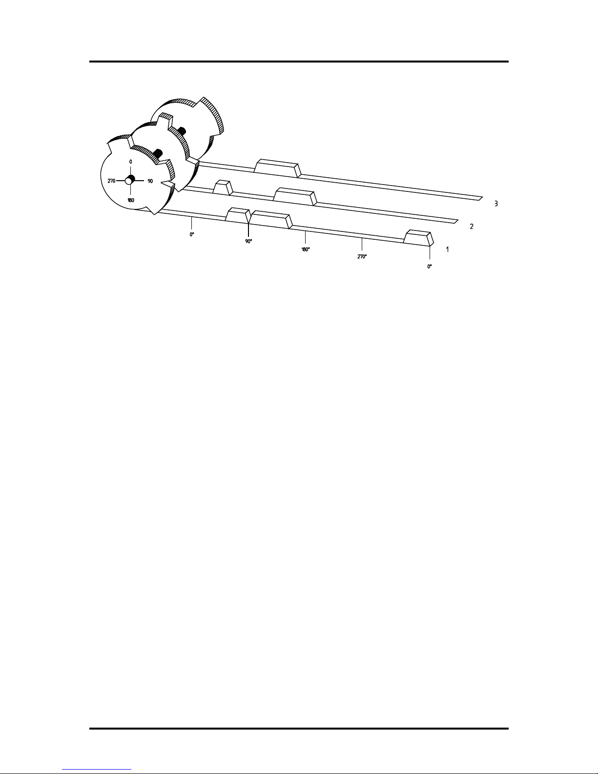
Fig.:Presentation of the principle of a cam switch unit
For a better understanding of the function of a cam switch unit, its principle is presented here. It has 3
outputs containing the following cams:
Output 1:Cam 1:Activation point60°Deactivation point85°
Cam2:Activation point95°Deactivation point145°
Cam3:Activation point325°Deactivation point355°
Output 2:Cam 1:Activation point5°Deactivation point20°
Cam2:Activation point95°Deactivation point145°
Output 3:Cam 1:Activation point30°Deactivation point85°
The 3 as beds presented progressions of the output signals occur, if the 3 cam plates turn
anticlockwise past a sensor, which scans the cams on the 0° axis.
The duration of the activation of a mechanical cam switch unit, i.e. the range between the on and off
position, is determined by the length of the cams.The length and the position of the cams can only be
limitedly varied, which additionally demands a relatively high mechanical and chronological
expenditure.With the CamCon, these adjustments are realisable in a fraction of a second, besides the
numberof the cams per bed is optional.A measuring system, which has been connected to the device
reports the position to the CamCon.The CamConcompares this with the programmed on and off
positions from all the outputs.If a position appears in a range of a programmed on / off position
(cams), all affected outputs will be switched.
Version from:04.06.2002Page:5
Digital Cam Switch UnitDigitronic
CamCon DC30Automationsanlagen GmbH
2.1. Delay time compensation
Every mechanical switching part (e.g. relays, magnetic valves) possesses a delay time, i.e. between
the triggering signal and the actual switching of the contacts passes a certain amount of time. Because
of that, problems can arise during procedures in which positionings are carried out in a moved system.
If such a process is driven with different speeds, different positionings will arise. One would have to
generate new (de)activation points for the switching signals for every speed in order to overcome this.
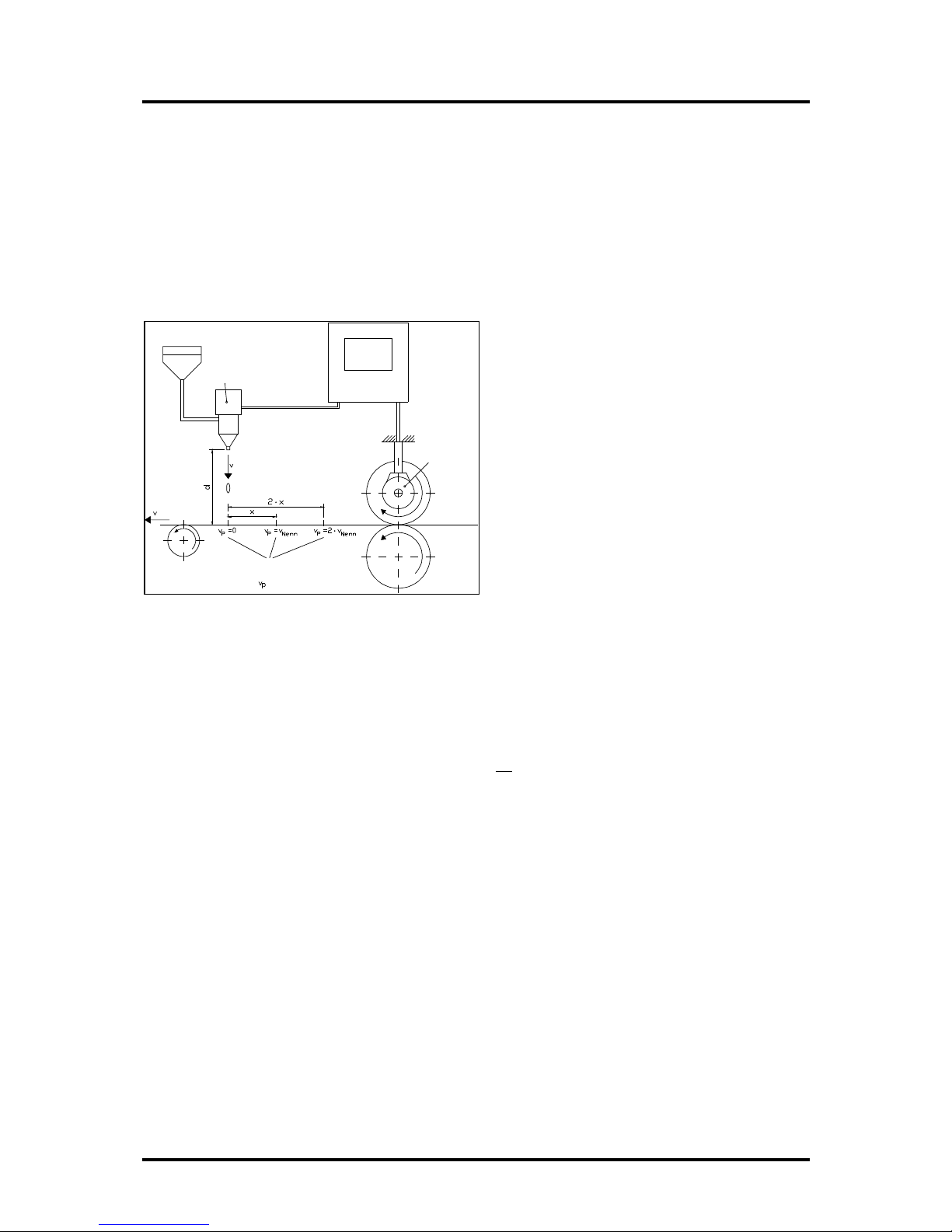
To explain the problem of the delay time compensation, the context shall be clarified using the
example of a packaging machine. During the process which is presented by the drawing, a dot of glue
is to be applied onto a precicely defined spot of a past going paber web.
magnetic valve
glue nozzle
drop
paper
Points where the glue
hits the paper at the
different speeds.
paper track
encoder
CamCon
The system has the following parameters:
v
p
-Speed of the paper web
v
T
-Falling speed of the drop of glue
d-Distance between the glue nozzle and
the paper web
T
MV
-Delay time of the magnetic valve
This happens without delay time compensation:
As soon as the measuring system reaches a certain position, the CamCon sends out an impulse to the
magnetic valve. This opens the glue nozzle for a short time, out of which the drop of glue then shoots.
Between the placing of the impulse and the falling of the drop passes a certain time, which is mainly
based on the delay time of the magnetic valve TMVAnother delay results in the time in which the drop
needs to cover the distance d between the glue nozzle and the surface of the paper.
This flight time can be calculated with:
t
Flight
=
d
v
T
So a delay time of tFlight+TMVresults altogether. During this time,, the paper web moves a certain
distance further on. One could now decrease the position at which the magnetic valve is activated, so
that the drop of glue hits the same spot as during standstill. One gains a delay time compensation in
this way, which however can only function at one single speed of the paper. As soon as the speed of
the system and the paper web is e.g. doubled, the landing range of the drop of glue is moved again by
the distance x, so that it would, without delay time compensation, move to the rear by twice the
distance (2 ⋅ x) altogether.
The automatic delay time compensation of the CamCon makes it now possible to operate with
processes with variable speeds. The CamCon gathers the speeds of the system continually and
adjusts the cams, which define the moments of switching, on line in dependence of the speed.
According to this, the outputs of the switching parts are being switched on or off earlier. The direction
of movement is of no importance.
Page:6Version from:04.06.2002

DigitronicDigital Cam Switch Unit
Automationsanlagen GmbHCamCon DC30
A small numerial example shall serve the illustration:
Assuming that the drive roll with the measuring system has a circumference of 360mm, so that one
millimeter at the circumference corresponds exactly to one angle degree of the measuring system.
The unit has the following parameter:
vdrop=20m/s
d=20cm
T
MV
=20ms
Out of this results a flight time of the drop to
tFlight=
d
v
T
=
0,2m
20m/s
=10ms
So the complete delay time amounts to Tdead
, altogether
= TMV+ tFlight = 20ms + 10ms = 30ms
During this time the paper web travels by the distance x = vpaper ⋅ Tdead
, altogether
= 1m/s ⋅ 30ms =
30mm further on.
The switching point of the magnetic valve has to be transfered 30° to the front to compensate this
delay time.
If one doubles the speed of the system and with that vpaper, the distance x, by which the paper web is
moving on, is also doubled. In this case the switching point has to be transfered by 60° .
Tip: Note that in this explanation the delay time is a solid quantity, which is determined by the
mechanical regulation and switching parts as well as by the measurement of the construction,
hence it does not change.
If one were now to program the complete delay time of 30ms on the appropriate output of the
CamCon, the drop of glue would always hit the exact spot at any speed.
Version from:04.06.2002Page:7

Digital Cam Switch UnitDigitronic
CamCon DC30Automationsanlagen GmbH
2.1.1. Calculating the delay time
There are several possibilities for calculating the delay time of a relay or a valve.
2.1.1.1. Calculating the delay time through relocations that have already occured
Program the switching point of the relay or valve during a standstill of the machine. We use the
switching point of 200 degrees in our example. If the machine is now run with a speed of e.g 40 min
-1,
a relocation occurs because of the delay time. This relocation is measured and is 40 degrees in our
example.
Attention: To calculate the relocation correctly you have to set the programmed delay time of the
cam switch unit to zero.
The delay time of the switching member is calculated according to the following formula:
Delay time ( in sec. ) =
∆ way(indegrees)*60(sec./min.)
speed(inmin-1)*360(degrees/rotations)
Delay time ( in sec. ) =
40*60
40*360
= 0.1667 sec.
The calculated delay time is now set in the CamCon.
2.1.1.2. Calculating the delay time through the difference of measured values
The switching point is determined at a speed of e.g. 50 min-1. In our example, the programmed
switching point is at 200 degrees. The second measurement occurs at a speed of 80 min-1. The
needed switching point has to be set to 160 degrees to reach the exact switch point again at 80 min-1.
Attention: To determine the two switching points you have to set the programmed delay time of the
cam switch unit to zero.
The delay time of the switching member is calculated with the following formula:
Delay time ( in sec. ) =
∆ way(indegrees)*60(sec./min.)
∆ speed(inmin-1)*360(degrees/rotations)
Delay time ( in sec. ) =
40*60
30*360
= 0.222 sec.
The determined delay time is now entered into the cam mechanism. Since this delay time is set for the
whole range of the speed, it now becomes necessary to adjust the cam to the speed at 0 min-1. To
determine the exact activation point you have to enter the difference to the speed 0 min-1at the first
measured activation point. The difference is calculated according to the following formula:
∆ way (in degrees) =
deadtime(insec.)*∆time(inmin-1)*360(degrees/rotations)
60(sec./min.)
∆ way (in degrees) =
0.222*50*360
60
= 66.6 degrees
The activation point of the cam is now relocated by 67 degrees, from 200 degrees to 267 degrees.
Page:8Version from:04.06.2002
 Loading...