

Digitrex 3-3000-00a-F User Manual

Mark III Directional Drilling
Locating System
Operator’s Manual
DCI Headquarters
nd
19625 62
Kent, Washington 98032 USA
Tel 425 251 0559
Fax 253 395 2800
E-mail DCI@digital-control.com
www.digitrak.com
Ave. S., Suite B-103
/ 800 288 3610
DCI Europe
Kurmainzer Strasse 56
D-97836 Bischbrunn
Germany
Tel +49(0) 9394 990 990
Fax +49(0) 9394 990 999
DCI.Europe@digital-control.com
DIGITAL
ONTROL
C
I
NCORPORATED
DCI India
SCO # 259, Sector 44-C
Chandigarh (UT) 160 047
Punjab, India
Tel +91(0) 172 464 0444
Fax +91(0) 172 464 0999
DCI.India@digital-control.com
DCI China
USA Excalibre
2803 Bldg C, 70 Cao Bao Rd
Shanghai P.R.C. 200233
Tel +86(0) 21 6432 5186
Fax +86(0) 21 6432 5187
DCI.China@digital-control.com
DCI Australia
2/9 Frinton Street
Southport, Queensland 4215
Australia
Tel +61(0) 7 5531 4283
Fax +61(0) 7 5531 2617
DCI.Australia@digital-control.com

DIGITAL CONTROL INCORPORATED
3-3000-00-F
© 1999-2006 by Digital Control Incorporated. All rights reserved. July 2006 Edition.
Trademarks
®
The DCI logo, CableLink®, DataLog®, DigiTrak®, Eclipse®, iGPS®, Intuitive®, look-ahead®, SST®, target-in-
the-box
LT™, TeleLock™, and TensiTrak™ are trademarks of Digital Control Incorporated.
®
, and Target Steering® are U.S. registered trademarks and DucTrak™, FasTrak™, SuperCell™,
Patents
The DigiTrak® Locating System is covered by one or more of the following U.S. Patents: 5,155,442;
5,337,002; 5,444,382; 5,633,589; 5,698,981; 5,726,359; 5,764,062; 5,767,678; 5,878,824; 5,926,025;
5,933,008; 5,990,682; 6,002,258; 6,008,651; 6,014,026; 6,035,951; 6,057,687; 6,066,955; 6,160,401;
6,232,780; 6,396,275; 6,400,159; 6,525,538; 6,559,646; 6,593,745; 6,677,768; 6,693,429; 6,756,783;
6,756,784; 6,838,882; 6,924,645; 6,954,073; 7,015,697; 7,049,820; 7,061,244. Sale of a DigiTrak
Receiver does not convey a license under any patents covering the DigiTrak
drill housing. Other patents pending.
®
Transmitter or underground
®
Important Notice
All statements, technical information, and recommendations related to the products of Digital Control
Incorporated (DCI) are based on information believed to be reliable, but the accuracy or completeness
thereof is not warranted. Before utilizing any DCI product, the user should determine the suitability of the
product for its intended use. All statements herein refer to DCI products as delivered by DCI and do not
apply to any user customizations not authorized by DCI nor to any third-party products. Nothing herein
shall constitute any warranty by DCI nor will anything herein be deemed to modify the terms of DCI’s
existing limited warranty applicable to all DCI products.
FCC Compliance Statement
This equipment has been tested and found to comply with the limits for a Class B digital device, pursuant
to Part 15 of the Rules of the Federal Communications Commission. These limits are designed to provide
reasonable protection against harmful interference in a residential installation. This equipment generates,
uses, and can radiate radio frequency energy and, if not installed and used in accordance with the
instructions, may cause harmful interference to radio communications. However, there is no guarantee
that interference will not occur in a particular installation. If this equipment does cause harmful interference to radio or television reception, which can be determined by turning the equipment off and on, the
user is encouraged to try to correct the interference by one or more of the following measures:
¾ Reorient or relocate the DigiTrak Receiver.
¾ Increase the separation between the problematic equipment and the DigiTrak Receiver.
¾ Connect the equipment into an outlet on a different circuit.
¾ Consult the dealer for help.
Changes or modifications to the DCI equipment not expressly approved and carried out by DCI will void
the user’s limited warranty and the FCC’s authorization to operate the equipment.
ii DigiTrak® Mark III Operator’s Manual

®
DIGITAL CONTROL INCORPORATED
Table of Contents
SAFETY PRECAUTIONS AND WARNINGS..................................................................................vi
INTRODUCTION..............................................................................................................................1
Basic DigiTrak Equipment...................................................................................................1
Basic DigiTrak Operation.....................................................................................................2
Technical Support................................................................................................................3
RECEIVER .......................................................................................................................................5
Display Window Icons .........................................................................................................6
On/Off..................................................................................................................................7
Receiving the Transmitter’s Signals....................................................................................8
Clicking vs. Holding the Trigger ..........................................................................................8
Changing the Receiver’s Channel Setting...........................................................................9
Changing the Depth Measurement Units (English vs. Metric) ..........................................10
Battery Status Display for Receiver and Transmitter ........................................................10
Warning Tones for Transmitter Overheat..........................................................................11
Ultrasonic Function............................................................................................................11
Setting the Ultrasonic Distance or Height-Above-Ground Measurement....................12
Zeroing the Ultrasonics................................................................................................12
Calibrating the Receiver....................................................................................................13
1-Point Calibration Procedure .....................................................................................13
2-Point Calibration Procedure.....................................................................................14
Calibrating with Transmitter Underground at Shallow Depth (<10 ft).........................16
Using Depth Antenna Plumb Line to Mark Locate Points ................................................16
Finding Firmware Version..................................................................................................17
5.0 Series Firmware Functions..........................................................................................17
Predicted Depth Key Points........................................................................................17
Procedure for Observing the Predicted Depth............................................................18
Viewing the Transmitter’s Temperature and the Receiver’s Battery Status ..............18
Viewing the Receiver’s Battery Voltage......................................................................18
Off Feature..................................................................................................................18
Accessing the Receiver’s Running Time Meter..........................................................18
TRANSMITTER..............................................................................................................................19
How a Transmitter Works..................................................................................................19
Batteries.............................................................................................................................20
Temperature Display.........................................................................................................20
Battery Status Display.......................................................................................................20
Temperature Overheat......................................................................................................20
Sleep Mode (Automatic Shutoff)........................................................................................21
Verifying Proper Fit of Transmitter in Housing ..................................................................21
Locating the Transmitter....................................................................................................23
Sensitive-Pitch Transmitters..............................................................................................23
Transmitter as an Inclinometer..........................................................................................23
Serial Numbers..................................................................................................................24
Specifications.....................................................................................................................24
DigiTrak® Mark III Operator’s Manual iii

IGITAL CONTROL INCORPORATED
D
Table of Contents (Cont.)
REMOTE DISPLAY SYSTEM........................................................................................................25
On/Off and Setting the Channel........................................................................................26
Transmitter Temperature and Battery Status....................................................................26
Remote Steering................................................................................................................27
Finding Firmware Version..................................................................................................28
DataLog Capability............................................................................................................28
BATTERY CHARGER....................................................................................................................29
Charging a Battery.............................................................................................................30
Conditioning a Battery in the Charger...............................................................................31
Conditioning a Battery Manually........................................................................................31
Indicator Lights and Meanings...........................................................................................31
SYSTEM OPERATING INSTRUCTIONS ......................................................................................33
Start-up Procedure............................................................................................................33
Shutdown Procedure.........................................................................................................33
Moisture and Temperature Avoidance..............................................................................33
Optimal Operating Temperatures......................................................................................34
General Maintenance........................................................................................................34
SIGNAL INTERFERENCE .............................................................................................................35
Electrical Interference/Background Noise Check..............................................................35
Suggestions for Dealing with Interference.........................................................................36
OPERATIONAL TESTS .................................................................................................................37
Self-Test for Mark III Receivers.........................................................................................37
Receiver Balance Check...................................................................................................37
Receiver Gain Test............................................................................................................38
Transmitter Tests...............................................................................................................38
Transmitter Salt Water Range Test...................................................................................40
Transmitter Battery Tests..................................................................................................41
LOCATING .....................................................................................................................................43
Locate Points (FNLP & RNLP) and Locate Line (PLL) .....................................................43
Handling the Receiver.......................................................................................................44
Distance Between FNLP and RNLP Due to Depth, Pitch, and Topography.....................44
Using Plus/Minus Indicators for Locating..........................................................................45
Locating the Transmitter from the Drill..............................................................................45
Finding the Rear Negative Locate Point (RNLP)........................................................45
Finding the Positive Locate Line (PLL).......................................................................46
Finding the Front Negative Locate Point (FNLP)........................................................47
Finding the Transmitter and Its Depth.........................................................................48
Locating the Transmitter from the Front............................................................................49
Method for Confirming Position.........................................................................................49
Locating on the Fly............................................................................................................50
Off-Track Locating.............................................................................................................50
Splitting the Front and Rear Negative Locate Points ........................................................51
Four Turn Technique.........................................................................................................51
®
iv DigiTrak® Mark III Operator’s Manual

®
DIGITAL CONTROL INCORPORATED
Table of Contents (Cont.)
LOCATING (Cont.)
Calculating Depth Based on Distance Between FNLP & RNLP .......................................52
Running Off Pitch or Calculating Depth from Pitch ...........................................................53
Transmitter’s Signal Shape ...............................................................................................54
Antennae Configuration.....................................................................................................54
Signal Reception ...............................................................................................................54
Front and Rear Negative Locate Points............................................................................55
Positive Locate Line Above Transmitter............................................................................55
CABLE TRANSMITTER SYSTEM .................................................................................................57
Power Supply.....................................................................................................................59
Cable Transmitter..............................................................................................................60
Remote Display with Cable Transmitter Capability...........................................................61
Viewing the Cable System Battery Status ........................................................................62
Operation...........................................................................................................................62
TROUBLESHOOTING ...................................................................................................................63
GLOSSARY....................................................................................................................................69
APPENDIX......................................................................................................................................73
Depth Increase in Inches per 10-foot Rod.........................................................................74
Percent of Grade to Degree Conversions (1% Pitch Transmitters) ..................................75
Percent of Grade to Degree Conversions
(0.1% Pitch Transmitters or Sensitive Pitch)...............................................................76
Degree to Percent of Grade Conversions (1% Pitch Transmitters) ..................................77
Degree to Percent of Grade Conversions (0.1% Pitch Transmitters) ...............................78
Calculating Depth Based on Distance Between FNLP and RNLP....................................79
REMOTE TELEMETRY LICENSE
LIMITED WARRANTY
DigiTrak® Mark III Operator’s Manual v

IGITAL CONTROL INCORPORATED
D
Safety Precautions
and Warnings
Important Note: All operators must read and understand the following Safety
Precautions and Warnings before using the DigiTrak Locating System.
1 Serious injury and death can result if underground drilling equipment makes contact
with an underground utility such as a high-voltage electrical cable or a natural gas
line.
) Substantial property damage and liability can result if underground drilling equipment
makes contact with an underground utility such as a telephone, fiber-optic, water, or
sewer line.
®
) Work slowdown and cost overruns can occur if drilling operators do not use the
drilling or locating equipment correctly to obtain proper performance.
¾ Directional drilling operators MUST at all times:
•
Understand the safe and proper operation of drilling and locating equipment, including the
use of ground mats and proper grounding procedures.
•
Ensure that all underground utilities have been located, exposed, and marked accurately
prior to drilling.
•
Wear protective safety clothing such as dielectric boots, gloves, hard-hats, high-visibility
vests and safety glasses.
•
Locate and track the drill head accurately and correctly during drilling.
Comply with state and local governmental regulations (e.g., OSHA).
•
Follow all other safety procedures.
•
¾ The DigiTrak System cannot be used to locate utilities.
¾ Continued exposure to heat, due to frictional heating of the drill head from drilling in sand, gravel,
or rock without sufficient fluid flow around the Transmitter, can cause inaccurate depth to be
displayed and may permanently damage the Transmitter. For more information see “Temperature Overheat” in the Transmitter Section.
) The DigiTrak equipment is not explosion-proof and should never be used near
flammable or explosive substances.
vi DigiTrak® Mark III Operator’s Manual

®
DIGITAL CONTROL INCORPORATED
Safety Precautions
and Warnings (Continued)
¾ Prior to the start of each drilling run, test the DigiTrak System to confirm that it is operating
properly and check that it is providing accurate drill head location and heading information (see
Receiver Section) and accurate drill head depth, pitch, and roll information with the Transmitter
inside the drill head.
¾ During drilling, the depth will not be accurate unless:
•
The Receiver has been properly calibrated and the calibration has been checked for
accuracy so that the Receiver shows the correct depth.
•
The drill head has been located correctly and accurately and the Receiver is directly above
and parallel to the Transmitter in the tool underground or above the front negative locate
point (FNLP).
•
The Receiver height-above-ground or ultrasonic distance has been set correctly.
•
The Receiver is kept level.
¾ Interference can cause inaccuracies in the measurement of depth and loss of pitch, roll, or the
Transmitter’s location or heading. The locating operator should perform an electrical interference check prior to drilling (see “Electrical Interference/Background Noise Check” in the Signal
Interference Section).
•
Sources of interference include traffic signal loops, invisible dog fences, cable TV, power
lines, fiber-trace lines, metal structures, cathodic protection, transmission towers, and radio
frequencies.
•
Interference with the operation of the Remote Display may also occur from other sources
operating nearby on the same frequency, such as car rental agencies using their remote
check-in modules, other directional drilling locating equipment, etc.
¾ Carefully review this Operator’s Manual and the Di giTrak training video and be sure you always
operate the DigiTrak System properly to obtain accurate depth, pitch, roll, and locate points. If
you have any questions about the operation of the DigiTrak System, please call DCI’s Customer
Service Department at 425-251-0559 or 800-288-3610 betw een the hours of 6:00 a.m. and 6:00
p.m. Pacific Time, Monday through Friday, and we will assist you in any way possible.
REMEMBER
If you are having difficulty on the job, call DCI (425-251-0559 or
800-288-3610) and we’ll attempt to help you solve the problem.
DigiTrak® Mark III Operator’s Manual vii

IGITAL CONTROL INCORPORATED
D
Dear Customer:
We would like to thank you for choosing the DigiTrak Locating System. We are proud of
the equipment that we have been designing and building in Washington State since
1990. We believe strongly in providing a unique, high-quality product and standing
behind it with superior customer service and training.
We ask that you take the time to read this entire manual—especially the section on
safety. Also, please fill in the warranty registration and mail it in or fax it to us at 253395-2800. We will put you on the Digital Control mailing list and send you product
upgrade information and our monthly newsletter FasTrak™.
®
We also ask that you feel free to contact us at 425-251-0559 or 800-288-3610 if you are
experiencing any problems with the equipment or have any questions regarding its use.
Our Customer Service Department is available to provide assistance.
The DigiTrak equipment has evolved considerably since the first Mark I system in 1990.
Many of the improvements to the equipment have been made in response to our
customer’s needs and suggestions. This manual is written for all versions of the
equipment—from our first units to the most recent Mark III.
As this industry grows, we try to keep an eye on the future to develop equipment that
will make your job faster and easier. We encourage you to stay current by visiting our
web site on the Internet at
www.digitrak.com or calling us at 425-251-0559 or 800-288-
3610.
We welcome questions, comments, and ideas.
Digital Control Incorporated
Kent, Washington
July 2006
3-3000-00a-F
viii DigiTrak® Mark III Operator’s Manual
®
DIGITAL CONTROL INCORPORATED
Introduction
Receiver
Remote Display
Batt ery Cha rg e r
DigiTrak
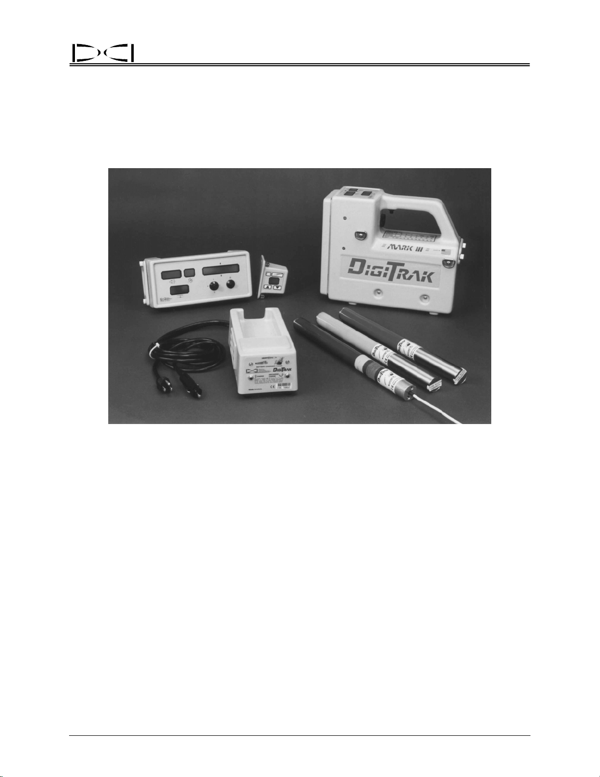
The DigiTrak Locating System is used during horizontal directional drilling operations for locating and
tracking the transmitter within the tool. This manual provides detailed information about the DigiTrak
System and how to use it. The main system components are the Receiver, the Transmitter, the Remote
Display, and the Battery Charger, which are described below. The optional DataLog
used with the DigiTrak equipment to record and map your drilling data. These systems can be upgraded
for use with the Cable Transmitter System, providing locating capability up to 140 ft (42.7 m) from the
transmitter.
DataLog
Module
Cable
Transmitter
®
Directional Drilling Locating System
Transmitters
®
System can be
Basic DigiTrak Equipment
Receiver – The DigiTrak Receiver receives signals from the transmitter, processes the signal information,
and displays the transmitter’s status (roll, pitch, depth/distance, predicted depth, battery, and temperature). It may also be equipped to send this information to the remote display at the drill. The most
current model of DigiTrak Receivers is the Mark III. Older versions are the Mark II or Mark I. Only on the
Mark III Receiver is the version identified; older versions are not specified on the receiver. If you need to
know what version you have, you can contact DCI.
Transmitter – Also referred to as a sonde, beacon, or probe, the DigiTrak Transmitter is placed in the drill
tool/housing to send information to the receiver. The receiver displays depth/distance, signal strength,
pitch, roll, battery, and temperature status. Power is supplied using C-cell alkaline batteries, except for
DigiTrak® Mark III Operator’s Manual 1

®
Introduction
the optional cable transmitter, which requires a 12V to 28V DC system. For gravity sewer installations,
DCI manufactures a sensitive-pitch transmitter that measures pitch in 0.1% increments.
Remote Display – The DigiTrak Remote Display unit enables the drill operator to view the transmitter’s
pitch, roll, depth, predicted depth, and temperature, and can also be used for remote steering when walkover tracking is not possible.
Battery Charger – The DigiTrak Battery Charger is used to charge and condition the DigiTrak NiCad
battery packs. May be used with AC or DC sources and is easily adapted for worldwide usage.
DataLog System – The DigiTrak DataLog System is an optional “as-built” mapping system used for recording and plotting the borepath location.
Cable Transmitter System – The DigiTrak Cable Transmitter System is an optional add-on deep locating
system used for borepaths that are deeper than 50 ft (15 m), have lengths that require several days to
drill, do not allow walkover locating, and/or are in high-interference areas.
Basic DigiTrak Operation
Safety Precautions and Warnings – All DigiTrak operators must review the safety precautions and
warnings provided at the front of this manual before using the DigiTrak System.
Trigger Click / Hold – The trigger under the receiver’s handle can be either clicked (pushed in and im-
mediately released in less than ½ second) or held in. These two actions provide different results and are
used in different operating procedures. (see “Clicking vs. Holding the Trigger” in the Receiver Section)
Calibration – The DigiTrak System requires calibration prior to first time use and when any of the
following equipment is introduced: transmitter, receiver, or transmitter housing. Calibration is not required every day; however, DCI recommends you verify the calibration by checking the distance readings
(bottom window) with a tape measure prior to the beginning of each drilling run. (see “Calibrating the
Receiver” in the Receiver Section)
Ultrasonic Distance / Height-Above-Ground Measurement – The ultrasonic distance or height-aboveground measurement is the distance between the DigiTrak Receiver and the ground. This distance is
measured by the two ultrasonic transducers on the bottom of the receiver. (see “Ultrasonic Function” in
the Receiver Section)
Depth vs. Distance – When the trigger is not held in, the bottom window of the receiver displays the
distance from the receiver to the transmitter, unless the receiver is out of range of the transmitter. Once
the receiver is on and calibrated, it is not necessary to wait for depth readings because the receiver
continuously measures this distance. When the receiver is directly above the transmitter, the information
in the bottom window is referred to as the depth. When the receiver is not directly above the transmitter,
the number in the bottom window is referred to as the “slant” distance. (see “Clicking vs. Holding the
Trigger” in the Receiver Section)
Predicted Depth – If the trigger is held in, the bottom window will display the predicted depth, which will
only be accurate if the receiver is at the front negative locate point (FNLP). The predicted depth is
displayed in the bottom window as a flashing number with a solid squiggle. (see “Clicking vs. Holding the
Trigger” and “5.0 Series Firmware Functions” in the Receiver Section)
2 DigiTrak® Mark III Operator’s Manual

®
Introduction
Operational Tests – Before drilling and during operation it is necessary to check the following: proper
calibration, correct ultrasonic measurement, status of battery power, transmitter temperature, and signal
interference problems. (see Operational Tests Section)
Locating – The DigiTrak System is used to locate the transmitter underground; the trigger under the
receiver’s handle is held in during locating to show signal strength in the upper left window. The operator
systematically follows the signals received from the transmitter to establish the FNLP and the rear
negative locate point (RNLP), which then guide the operator to the transmitter’s location. (see Locating
Section)
Tracking – The DigiTrak Receiver automatically “tracks” and displays the transmitter’s orientation (pitch/
roll) and distance. It is not necessary to push the trigger or take any other steps to see this information.
Troubleshooting – The DigiTrak System is a sensitive instrument whose operation can be affected by
many different factors. We have listed many of the common problems and solutions in the Troubleshooting Section in this manual. If you cannot find the answers you need there, then please call DCI for
assistance. (see “Technical Support” below)
Technical Support
If you are having difficulties with your DigiTrak System and cannot find solutions by reviewing this manual
or the DigiTrak Training Video, then call DCI’s Customer Service Department at 425-251-0559 or 800288-3610. When you call, you should be prepared to provide the following information:
¾ Serial numbers on the DigiTrak Receiver, Transmitter, Remote Display, etc.
¾ Description of problem.
¾ How you have tried to solve the problem.
¾ Availability of other equipment to troubleshoot with.
You may also want to visit our web site (
DCI@digital-control.com.
www.digitrak.com) for more information, or e-mail us at
DigiTrak® Mark III Operator’s Manual 3

Introduction
Notes
®
3-3000-00b-F
4 DigiTrak® Mark III Operator’s Manual

®
DIGITAL CONTROL INCORPORATED
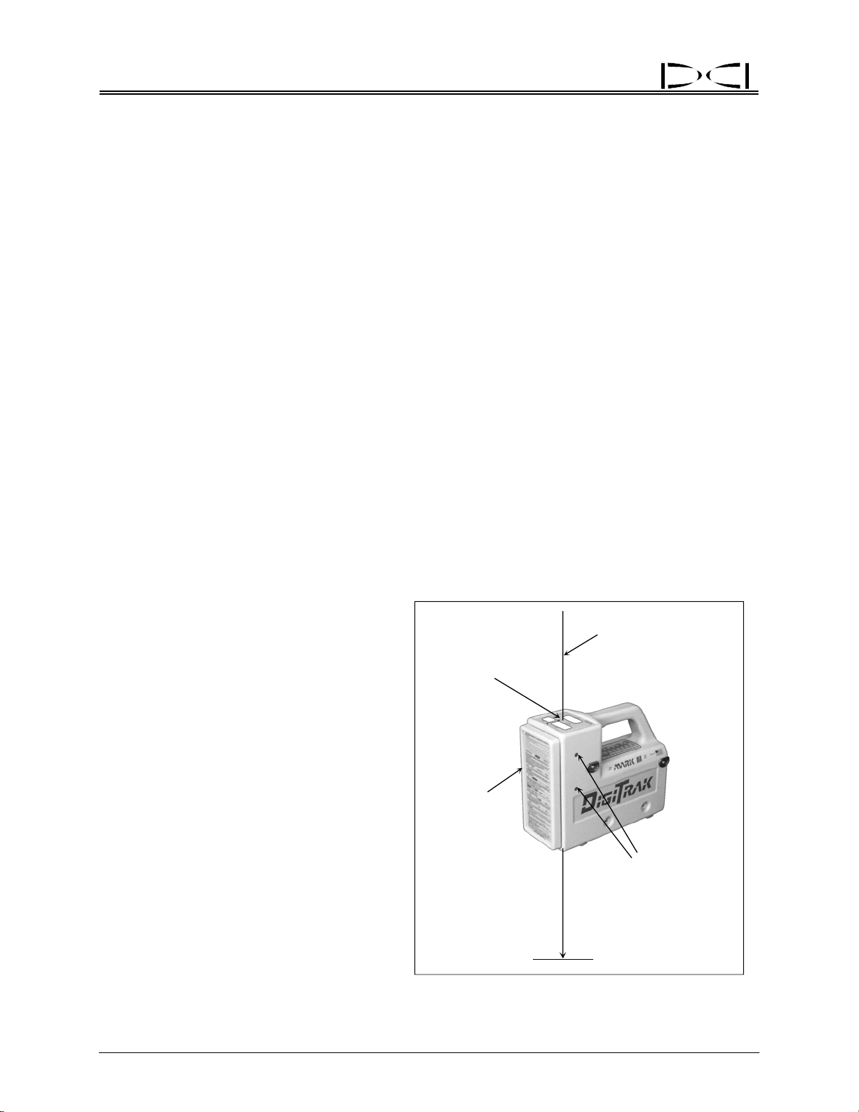
Receiver
Trigger
Temperature
& Distance
Conversion
Chart
Battery
Compartment
Back Panel
Pitch/Roll
Antenna Screws
Handle
Speaker
DigiTrak Receiver – Side View
The DigiTrak Receiver is a hand-held unit used for locating and tracking the transmitter. It receives and converts
signals from the transmitter and displays the following
information: pitch, roll, depth/distance, predicted depth,
temperature, and battery status. The display windows
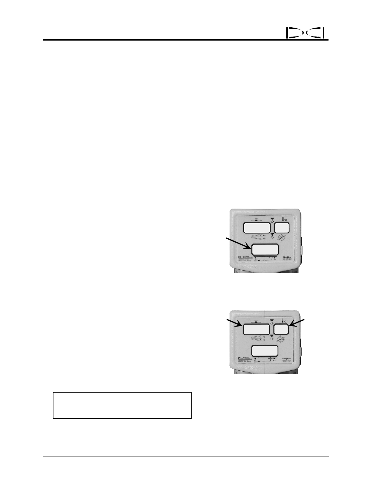
are located on the top of the receiver.
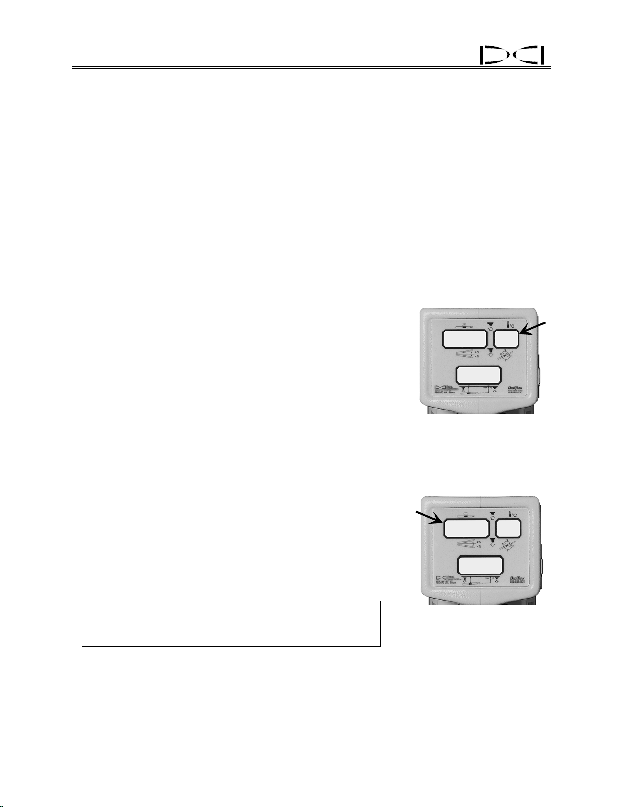
Next to each DigiTrak display window are symbols or
icons to help you identify the functions of each window
(see table on next page). The icons below each window
represent the pitch, roll, and depth/distance of the
transmitter, which are displayed when the trigger is
released, as shown by the trigger down icon. When the
trigger is held in (trigger up), the top left window will
display the signal strength and the top right window will
display the temperature. Note the predicted depth icon
below the bottom window. When the trigger is held in
and the receiver is positioned at the front negative locate
point (FNLP), the predicted depth of the transmitter at
the FNLP is displayed in the bottom window. This
predicted depth number will flash quickly and the bottom
window will also show a solidly illuminated squiggle (“~”)
to further set it apart from the depth display.
NOTE: Should the trigger be held in at any location
other than the FNLP, the predicted depth shown will not
be valid.
Display
Windows
Depth/Locating
Antenna Screws
Front Panel
Trigger Up
Signal
Strength
Pitch
Depth
DigiTrak Receiver
~
I 5
I
I
Temperature
8
8
– Top View
Showing Display Window Icons
Trigger
Down
Roll
Predicted
Depth
DigiTrak® Mark III Operator’s Manual 5
Receiver
+%
- %
12
9
3
6
x
Display Window Icons
Trigger down – Trigger is released; display windows show pitch, roll, and
distance/depth of the transmitter.
Pitch – Numbers from 0% to ±100% show the inclination of the transmitter with
respect to horizontal; 100% represents a 45° angle (top left window, trigger down).
Roll – Numbers from 1 to 12 show the roll position (1 o’clock to 12 o’clock) of the
transmitter (top right window, trigger down).
Depth – The bottom window displays the depth or slant distance of the transmitter
with respect to the surface of the ground when the trigger is down.
Trigger up – Trigger is held in; display windows show signal strength, transmitter
temperature, and predicted depth when operator is at FNLP.
Signal strength – Numbers from 0 to 999 are displayed to show the strength of the
signal from the transmitter (top left window, trigger up).
®
o
C
x
FNLP
–
+/
Transmitter temperature – Temperature of the transmitter in degrees Celsius (top
right window, trigger up).
Predicted depth – The bottom window displays the predicted depth of the
transmitter at the FNLP when the trigger is up and the receiver is at the FNLP.
Customer
Service
Phone
Numbers:
800-288-3610
and
425-251-0559
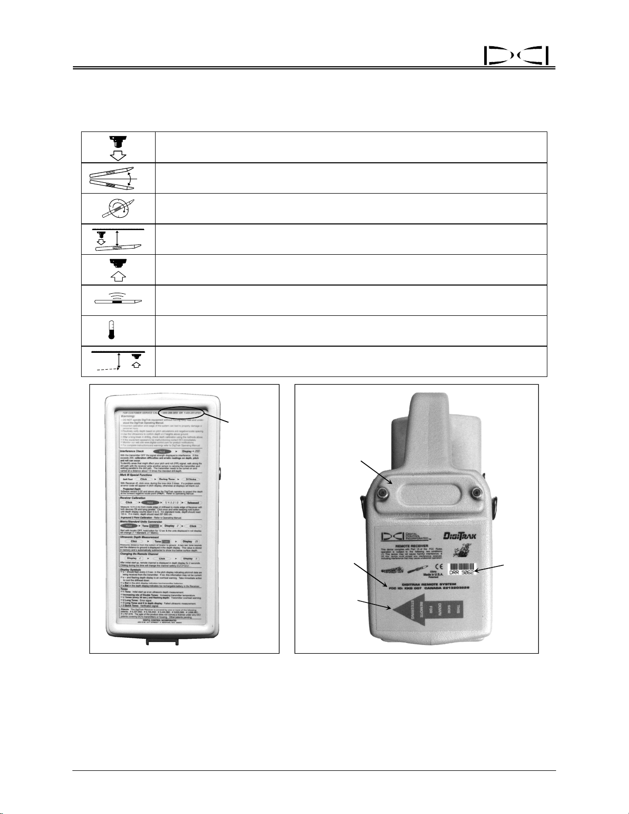
Orange Arrow
Battery
Compartment
Telemetry
Information
Indicates
Remote
Capability
Serial
Number
DigiTrak Receiver – Front Panel DigiTrak Receiver – Back Side
Showing Condensed Instructions Showing Identification Information
The front panel of the receiver has condensed instructions for quick field reference and DCI’s phone
numbers for troubleshooting assistance. There is also a sticker under the handle for temperature and distance conversions. The serial number is located on the back panel of the unit below the battery compartment; it is preceded by the letters DR or DRR (for DigiTrak Receiver and DigiTrak Remote Receiver,
6 DigiTrak® Mark III Operator’s Manual
®
Receiver
respectively). If there is an orange arrow below the serial number, then it is a remote receiver, and it is
capable of sending a signal to a remote display unit at the drill. All receivers can be upgraded to remote
capability. The Mark III Receivers (serial numbers greater than 4676) are also equipped with a backlit
display for dim viewing conditions. All receivers can be upgraded to have a backlit display.
DigiTrak equipment is like a computer in that it requires firmware. The firmware determines how a unit
will convey information. Over time, the firmware is changed and upgraded to accommodate new features
and functions in the system. New versions of the firmware are available for upgrading older systems, but
the firmware must be upgraded by DCI. To determine the firmware version installed in your equipment,
see “Finding Firmware Version” in the Receiver and Remote Display Sections.
All Mark III Receivers have the capability of performing a self-test to determine if the unit appears to be
operating properly. DCI recommends that you complete the self-test every day before locating (see “SelfTest for Mark III Receivers” in the Operational Tests Section).
IMPORTANT: The receiver is designed to be held comfortably in such a manner that it levels itself.
Keeping the receiver level is critical for the most accurate locating.
On/Off
To turn the receiver on:
1. Place a fully charged battery pack into the battery compartment, terminal end in first.
2. Click the trigger one time. The unit will sound a tone from the speaker adjacent to the trigger.
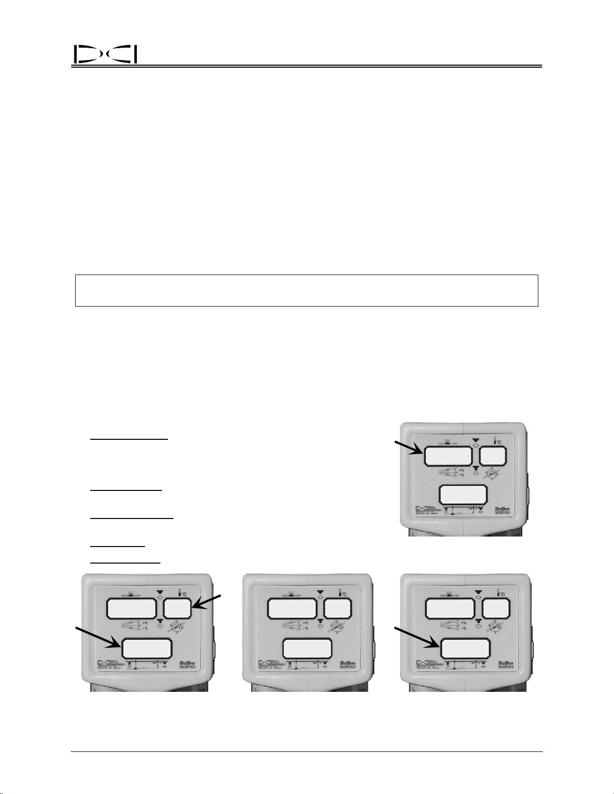
3. During the start-up sequence, the three display windows will quickly flash the following information, in
the order given here:
¾
Top Left Window: Firmware version in the receiver (version is
shown with no decimal point—e.g., 507 is version 5.07); older
units will display the firmware version only if the trigger is held in
at start-up.
¾
Bottom Window: Receiver’s battery voltage in tenths of a volt
(155 is 15.5V DC); older units will not display this information.
¾ Top Right Window: English or metric depth measurement units
(1 = inches, 2 = centimeters).
¾
All Windows: LCD test (888’s and all symbols will display).
¾
Bottom Window: Remote channel setting (0 = off, 1,2,3,4 = on).
~
507
I
BAT
+
888
88
507
Firmware Version
~
55
I
Depth Measurement Units
and Receiver Battery Voltage LCD Test Remote Channel Setting
DigiTrak® Mark III Operator’s Manual 7
BAT
–
888
I
2
®
Receiver
The depth measurement units (centimeters or inches) and remote channel setting can be changed only
during start-up (see “Changing Depth Measurement Units” and “Changing the Channel Setting” below).
After the start-up process, the windows will display pitch, roll, and distance if there is an active transmitter
within range (see Tracking Mode display below). If an active transmitter is not within range, 1999 will
appear in the bottom window and the top windows will be blank. If the bottom window is not displaying
1999 and there is no active transmitter within range, an unknown signal is present.
To turn the receiver off:
The receiver will automatically shut itself off if no signal is received for 15 minutes.
To turn off a receiver when a signal is present, click the trigger once and, during the tone, quickly click 4
times. All windows will blank out, signifying that the unit is off.
To turn off a receiver with pre-5.0 series firmware when a signal is present, the battery must be removed
manually.
(For more information on the 5.0 series firmware and operating/display differences, see “Clicking vs.
Holding the Trigger” and “5.0 Series Firmware Functions” in this section.)
Receiving the Transmitter’s Signals
After charged batteries are loaded into the transmitter (positive end
first), the receiver enters “tracking” mode and will display pitch in the
top left window, roll (12 positions) in the top right window, and depth
(or distance) in the bottom window. With the DigiTrak System it is not
necessary to push any buttons to receive pitch, roll, or depth/distance;
this information is updated and displayed automatically. The flashing
squiggle (“~”) in the top left window indicates that pitch and roll
updates are being received from the transmitter. For the best results,
wait for two squiggles with the same pitch/roll information before
giving a steering command to confirm the accuracy of the data.
Clicking vs. Holding the Trigger
Clicking the trigger versus holding the trigger will initiate different
modes with your receiver. When the trigger is held in (trigger up) the
receiver is in the “locating” mode, and the top left window will display
signal strength. Also displayed in the top left window, along with the
signal strength, are the plus (“+”) and minus (“–”) symbols. These
symbols are the key to locating the transmitter (see Locating Section).
The bottom window will display the predicted depth, along with a
flashing squiggle. The top right window will flash the transmitter’s
temperature in degrees Celsius.
~
I 5
Tracking Mode Showing
Pitch, Roll, Depth/Distance,
and Update Symbol
+
653
~
I
I
I
27
8
8
22
Locating Mode Showing
Signal Strength,
Transmitter Temperature,
and Predicted Depth
8 DigiTrak® Mark III Operator’s Manual

®
Receiver
For receivers that have pre-5.0 series firmware, the bottom window will continue to display the receiver’s
distance from the transmitter in the bottom window, not the predicted depth. (For more information, see
“5.0 Series Firmware Functions” in this section or see the Locating Section.)
Any time the trigger is clicked (pushed in and released in less than ½ second), the receiver will initiate an
ultrasonic measurement, which is also referred to as the height-above-ground measurement. This
measurement is the distance between the receiver and the ground, which is measured by the ultrasonic
transducers on the bottom of the receiver. An ultrasonic measurement can be taken an unlimited number
of times (reset) without affecting the receiver’s calibration. The ultrasonic function is independent of the
transmitter and measures the receiver’s elevation above the ground. The ultrasonic distance is
automatically subtracted from the distance to the transmitter to provide the operator with a display of the
transmitter’s depth/distance below the ground’s surface. The ultrasonics were designed to reduce the
effects of interference by increasing the separation between the interference source in the ground (e.g.,
rebar) and the receiver. (For more information, see “Ultrasonic Function” later in this section.)
Changing the Receiver’s Channel Setting
If using a remote display unit, the receiver and remote display unit must each be set to the same channel.
Changing the receiver’s channel selection can only be done at start-up.
To change the channel:
At the end of the start-up sequence, the bottom window will display the current remote channel setting (0,
1, 2, 3, or 4) for 2 seconds. During this time, the trigger can be clicked to change the channel to the
desired setting. This setting will remain until you change it. Replacing the batteries in any piece of
equipment will not affect the current channel setting, the ultrasonic setting, or the receiver’s calibration.
NOTE: A zero (0) remote channel setting indicates that the receiver’s telemetry signal is shut off and no
signal is being sent to the remote display unit. “Dashes” will appear across the three display windows on
the remote display to indicate no signal is being received. Setting the receiver to channel 0 can be done
to conserve the receiver’s battery (see Remote Display Section).
The DigiTrak System uses ultrahigh-frequency telemetry to communicate between the receiver and the
remote display. Both the receiver and the remote display must have the same type of telemetry to
communicate properly.
DigiTrak® Mark III Operator’s Manual 9
®
Receiver
Changing the Depth Measurement Units (English vs. Metric)
The DigiTrak Receiver is capable of displaying depth in either inches (English) or centimeters (metric).
The depth measurement units can only be changed during the start-up process.
To change the measurement units:
Instead of clicking the trigger to initiate start-up, simply squeeze and hold in the trigger for 12-14 seconds
(the unit may or may not make a tone during this time depending upon the firmware version). The top
right window will display a 1 or a 2 (1 = inches, 2 = centimeters). With the trigger still held in, the unit will
beep 3 times and then change to the other setting. When the desired setting is displayed, release the
trigger. This mode will remain the same until changed and is not affected by battery replacement.
Older receivers that have not been upgraded require a different method for changing the depth measurement units. Contact DCI Customer Service (425-251-0559 or 800-288-3610) for assistance.
Battery Status Display for Receiver and Transmitter
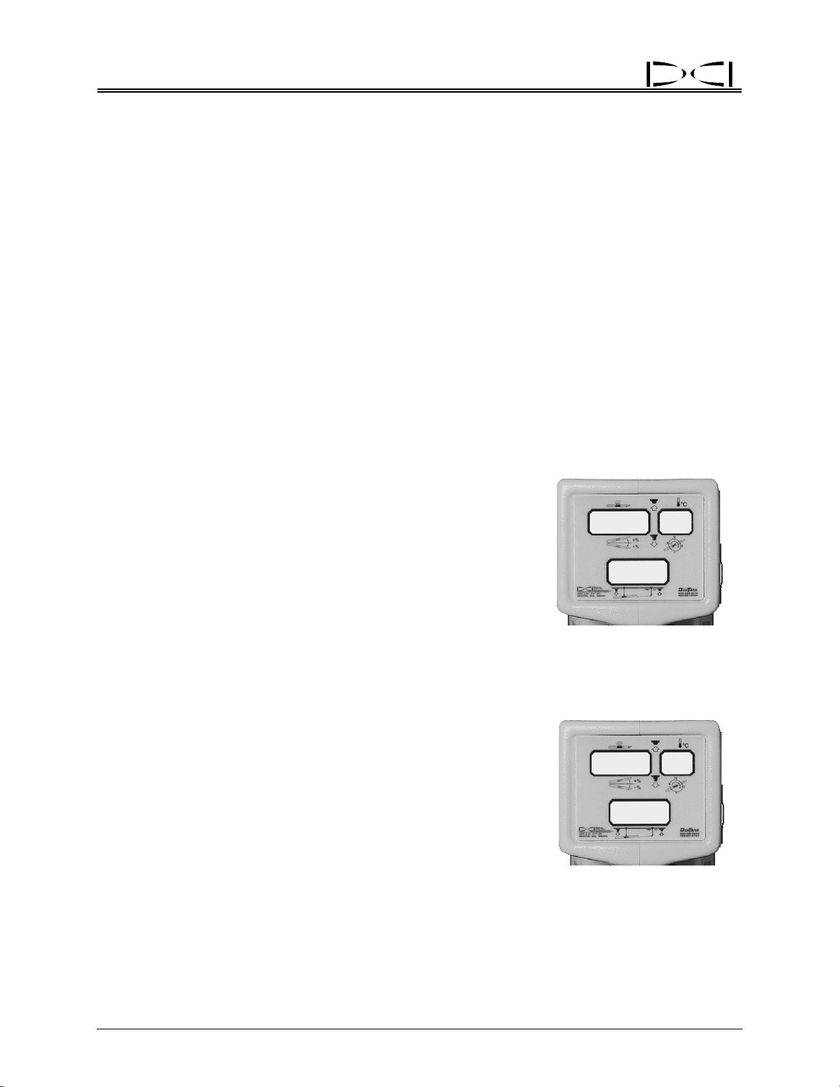
The receiver will prompt the operator when the rechargeable NiCad battery is low (approximately 1 hour of usage
left) by displaying BAT in the bottom window.
The receiver’s battery voltage is displayed in the bottom
window during start-up. It is the first information to be displayed in the bottom window. The voltage is shown in
tenths of a volt, for example, 155 is 15.5V DC. (For more
information about the NiCad’s associated voltages, see
the Battery Charger Section.)
The percentage of remaining battery life in the receiver
will display in the top right window after releasing a held-in
trigger (locating mode). It will display only as 99, 90, 75,
50, 25, 10, 5, or 0.
If you observe the BAT symbol in the top left window, then
the transmitter batteries are low, and the transmitter battery status should be checked. To view the percentage of
battery life remaining in the transmitter’s battery, hold and
then release the trigger. The status is displayed in the top
left window for 2 seconds, after which the pitch display will
resume. This information will display only as 100, 90, 75,
50, 25, 10, 5, or 0. The receiver’s NiCad battery percent
remaining also displays during this 2-second period in the
top right window.
NOTE: Mark III Receivers do not display
the transmitter battery and temperature
information until 4 minutes after start-up.
507
55
I
Receiver Battery Status,
Voltage Remaining
90
BAT
I
Transmitter (left) and Receiver (right)
Battery Life Remaining
in Percentages
I
75
9
I
10 DigiTrak® Mark III Operator’s Manual
®
Receiver
Warning Tones for Transmitter Overheat
Beginning with firmware version 3.76, the DigiTrak Receiver will emit a series of increasing warning tones
to signal transmitter overheating as follows:
Temperature Range Warning Signal
14°C and below
15°C to 35°C One double tone with every 4°C increase in temperature.
36°C to 45°C Two double tones with every 4°C increase in temperature.
45°C to 60°C Three double tones with every 4°C increase in temperature.
60°C and above
No audio or visual warnings.
Audible error tones (two long tones) and the bottom window will flash;
1999 may appear when the transmitter shuts down at about 80°C.
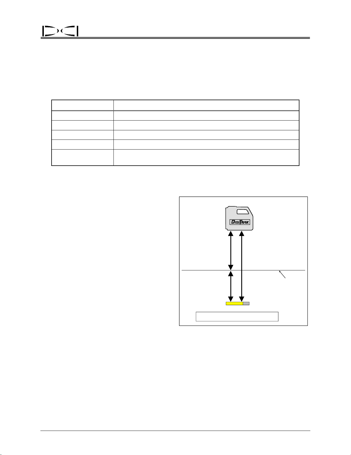
Ultrasonic Function
The ultrasonic function measures the receiver’s
elevation above the ground and subtracts that
distance from the total magnetic distance to
calculate the depth of the transmitter below the
ground’s surface. The ultrasonic function is designed to help the operator observe the depth
reading while maintaining separation between
the receiver’s antennas and potential sources of
interference. An ultrasonic measurement can
only be taken after start-up is completed.
The ultrasonic function is particularly useful when:
¾ Locating over obstacles.
¾ Obtaining adequate separation from utilities
in the ground or rebar interference.
Ultrasonic
Measurement
Depth
Magnetic
Distance
Surface of
Ground
¾ Locating above water.
¾ Verifying calibration when the transmitter is
underground.
¾ Recalibrating in the ground (see
Calibration” below).
The ultrasonic measurement is made by emitting and receiving signals from the two small round holes/
where transducers are mounted on the bottom of the receiver. When the trigger is clicked, one
transducer emits a high-frequency sound wave that travels to the nearest surface and bounces back to be
received by the other transducer. The time required for the signal to return is used to calculate the
distance to the ground. The operating range of the ultrasonic measurement is between 12 inches (30 cm)
and 90 inches (230 cm). The ultrasonic measurement is displayed in the bottom window for 2 seconds
after the trigger is clicked one time.
DigiTrak® Mark III Operator’s Manual 11
“2-Point
Depth = Magnetic – Ultrasonic
Use of Ultrasonic Measurement
To Determine Actual Depth

®
Receiver
Following are some general points regarding the ultrasonic function:
¾ The ultrasonic function in the receiver is independent of the transmitter receiving functions.
¾ A single click to activate the ultrasonic function can be used an unlimited number of times without
affecting the receiver’s calibration.
¾ The ultrasonic measurement is held in memory until the trigger is clicked again for a new ultrasonic
measurement or until t h e r ec e i v er t ur n s o ff .
¾ The
¾ The ultrasonic setting will require resetting after a 2-point calibration.
ultrasonic measurement will be reset to zero after completing a 1-point calibration.
Setting the Ultrasonic Distance or Height-Above-Ground Measurement
1. Hold the receiver comfortably and level in your hand as you would during locating/tracking.
2. Click the trigger (the receiver must already be powered up). This will initiate the ultrasonic measurement.
3. A single tone is emitted during which the ultrasonic distance is displayed for 2 seconds in the bottom
window before the depth/distance display resumes. The bottom window will now display the
transmitter’s depth below the ground instead of the total magnetic distance.
Zeroing the Ultrasonics
1. Set the receiver on the ground or agains t some other flat surface.
2. Click the trigger (the receiver must already be powered up). This will initiate the ultrasonic
measurement.
3. The receiver will beep 3 times and display a “0” in the bottom window for 2 seconds before the depth
display resumes.
IMPORTANT: If another crew member takes over the locating and does not reset the ultrasonics, the
depth display may be inaccurate. For instance, if one person holds the DigiTrak Receiver comfortably 20
inches (50 cm) above the surface of the ground, and another person begins to locate the tool by setting
the DigiTrak on the ground (without zeroing the ultrasonics), the tool will appear to be 20 inches shallower
because the DigiTrak is still subtracting the 20-inch ultrasonic distance.
NOTE: If by chance the trigger is clicked twice within a 1 or 2 second period, the receiver will
enter into a 2-point calibration mode. Wait until all the tones stop before touching the
trigger again. Otherwise the calibration could be changed.
12 DigiTrak® Mark III Operator’s Manual

®
v
r
r
Receiver
Calibrating the Receiver
There are two different calibration methods: 1-point and 2-point. The 1-point calibration is performed
with the transmitter in the housing parallel to and 10 ft 5 in. (3.18 m) from the receiver, as described
below. A 2-point calibration is generally performed when the transmitter is below ground and it is not
possible to perform a 1-point calibration.
Calibration is necessary prior to first time use and when any of the following occur:
¾ The transmitter is changed.
¾ The receiver is changed.
¾ The housing/drill tool is changed.
Do not calibrate if:
¾ You are within 10 ft (3 m) of metal structures, such as steel pipe, chain link fence, metal siding, con-
struction equipment, or automobiles.
¾ The receiver is over rebar or underground utilities.
¾ The receiver is in the vicinity of excessive electrical interference (see “Electrical Interference/
Background Noise Check” in the Signal Interference Section).
¾ The transmitter is not installed into the housing.
¾ The transmitter is not turned on.
NOTE: Calibration should be checked at 10 ft 5 in. (3.18 m) daily and before every use. Calibra-
tion only affects the depth/distance reading, not pitch or roll.
1-Point Calibration Procedure
1. Confirm the lack of interference (see Electrical Interference/Background Noise” Check in the Signal
Interference Section). Make sure there are no other active transmitters within range of the receiver.
2. Place an operating transmitter inside the housing on level ground.
3. After the receiver has completed the start-up sequence, place it exactly 10 ft 5 in. (3.18 m) from the
housing as shown in the sketch (a tape measure must be used for accuracy; measure from centerline
of transmitter to inside edge of receiver). Hold in the trigger to confirm a stable signal, then release
the trigger; note signal strength
reading. The signal strength must
be at least
calibration. If your reading is less
than 250, the transmitter may be
malfunctioning, and you should call
DCI.
250 points for proper
10 ft 5 in. (3.18 m)
e
Recei
Determining 1-Point Calibration Signal
Transmitter
Centerline
Transmitte
(Inside
Housing)
DigiTrak® Mark III Operator’s Manual 13

®
Receiver
4. Click the trigger one time.
5. The receiver will beep. During the beep, pull in the trigger and hold it.
6. Continue to hold the trigger and watch the countdown (from 5 to 0) displayed in the bottom window.
This countdown is accompanied by a chirping sound.
7. When the countdown reaches zero, let go of the trigger.
8. A good calibration will be confirmed by 3 short beeps. Two long tones indicate a failed calibration,
which may be due to an inadequate signal from the transmitter or interference.
9. The bottom window should display 120 inches (±2 inches) or 297 cm (±5 cm).
10. Using a tape measure for precise positioning, as in step 3, move the receiver to at least two other
locations (e.g., 60 inches [152 cm] and 240 inches [610 cm]) and confirm proper depth/distance
readings. Verify that your target drilling depth displays accurately.
11. Note the signal strength for possible later use.
Confirming Proper Calibration
Check the calibration using a tape measure with the transmitter above ground in the housing. Place the
receiver parallel to the housing at a series of accurately measured distances, and verify that the distance
displayed in the bottom window corresponds to the distance on the tape measure. If there is a considerable discrepancy between the measured distance and that displayed on the receiver (greater than ±5%),
then recalibrate.
2-Point Calibration Procedure
A 2-point calibration is used when the transmitter is below ground. It is recommended that more than one
2-point calibration procedure be conducted to verify a good calibration. Two procedures are given
below—one for newer receivers and one for older receivers (manufactured before 1995 and never
upgraded).
To calibrate (newer receivers):
1. Confirm the lack of background interference by first waiting for the transmitter to fall asleep (10–15
minutes). An acceptable background interference should show a signal strength of less than 150
points (in the top left window with the trigger held in). Make sure that there are no other active
transmitters within range of the receiver. (See “Electrical Interference/Background Noise Check” in
the Signal Interference Section.)
2. Turn on the transmitter if it is still asleep by rotating the drill string. Position the receiver parallel to
and directly over the transmitter; the transmitter’s pitch must be less than 20%. The ground surface
under the receiver must be relatively solid, flat, and level. The receiver should be displaying pitch,
roll, and distance.
3. Hold the receiver level, directly above the transmitter, and at least 12 inches (30 cm) above ground.
4. Click the trigger; you will hear a tone.
14 DigiTrak® Mark III Operator’s Manual

®
Receiver
5. During the tone, click the trigger again and continue to hold the receiver level and steady. You will
then hear 2 beeps followed by a long 6-second tone, indicating that the first calibration point is found.
6. During the 6-second tone, raise the receiver straight up, keeping it level and in the same plane above
the transmitter, as high as you comfortably can. Before the 6-second tone ends you must steady the
receiver and click the trigger.
7. Continue to hold the receiver in this position until you hear 3 beeps indicating that the second
calibration point was found and the calibration procedure is com plete.
8. Reset the ultrasonic measurement to zero and check the depth reading while the receiver is sitting on
the ground directly above the transmitter. To verify a good calibration, check the depth at two
different elevations above ground using the ultrasonics, as described below under “Confirming Proper
Calibration.”
NOTE: If you hear 2 long beeps, there has been a calibration error, which can be caused by
an unstable or weak signal or a failed ultrasonic reading.
To calibrate (older receivers manufactured prior to 1995 that haven’t been updated):
1. Place the transmitter into the drill head housing and place on the ground.
2. Cover the transmitter with a flat surface (e.g., a clipboard, piece of cardboard, plywood, etc.) to provide an ultrasonic response surface.
3. With the trigger held in, position the receiver over the tool using the plus/minus (“+/–”) flip to verify that
the receiver is directly over the transmitter’s antenna. Be sure that the signal strength is less than
200 (top left window). If it is more than 200, raise the receiver slightly.
NOTE: Mark I Receivers without upgrades do not show 0-999 signal strength. You should
see a 7 in the top right window (gain stage 7) and a value of 200 or less in the top left
window when performing the 2-point calibration.
4. Follow the instructions given above for calibrating newer receivers beginning with step 4.
Confirming Proper Calibration
The ultrasonic function can be used to confirm proper calibration when the transmitter is below ground.
Check the depth measurement with the receiver held at one position (above the transmitter), then raise
the receiver to a new elevation, click the trigger to set the ultrasonics, and note the depth reading. If the
depth readings are the same (within 2 inches [5 cm]), then the calibration is good. If the depth readings
are not within 2 inches, then the depth/distance readings cannot be relied on and recalibration should be
performed.
DigiTrak® Mark III Operator’s Manual 15
®
Receiver
Calibrating with Transmitter Underground at Shallow Depth (< 10 feet)
Should recalibration be necessary when the transmitter is below ground at depths less than 10 ft (3 m), it
is possible to conduct a modified 1-point calibration procedure. This requires knowing the signal strength
of the transmitter in the housing at 10 ft. (You should always note the value of the signal strength when
you first perform a 1-point calibration.)
With the transmitter below ground (shallower than 10 ft), place the receiver parallel to the transmitter at a
distance to cause the same signal strength as noted during the most recent 1-point calibration. To do
this, simply hold in the trigger and move the receiver away from or closer to the transmitter until you see a
signal strength reading (top left window) that equals the 1-point calibration signal. Set the receiver on the
ground, and complete the 1-point calibration procedure. However, if the transmitter is deeper than 10 ft, it
will be necessary to perform a 2-point calibration.
For example, if you noted that the signal strength during the most recent 1-point calibration was 560, then
move the receiver parallel to the transmitter to a distance that will result in a reading of 560 and complete
the procedure for a 1-point calibration. Remember, this procedure will not work if you are drilling deeper
than 10 ft. If this is the case, you will have to perform a 2-point calibration, or, if a spare transmitter is
available, you can calibrate to it at a distance equivalent to 560 points of signal (or whatever the signal
strength was during the most recent 1-point calibration) and then resume drilling with the same transmitter that is below ground.
When using this modified procedure, you are assuming that the in-ground transmitter is still performing at
the same signal strength it was when the most recent 1-point calibration was performed. If the transmitter
has been damaged or has overheated, this modified procedure should not be relied upon.
Using Depth Antenna
Plumb Line to Mark
Plumb Line
Locate Points
Center of
To mark the important locating positions
(the front negative locate point or FNLP;
the rear negative locate point or RNLP;
and the positive locate line or PLL) accu-
you must use the vertical axis (plumb
rately,
line) that runs through the center of the
display windows and bisects the depth/
locating antennas (see sketch at right).
Where this axis intersects the ground is the
location that you should mark. This plumb
line also serves as the axis around which
you can rotate the receiver for confirming
the FNLP and RNLP. (For more information, see “Method for Confirming Position”
in the Locating Section.)
Display
Windows
Front of
Receiver
Depth/Locating
Antenna Screws
Place Marker
Straight Down
on Ground
Depth Antenna Plumb Line
16 DigiTrak® Mark III Operator’s Manual

®
Receiver
Finding Firmware Version
It is possible to determine the firmware version in the receiver. This information is necessary to complete
troubleshooting diagnostics with DCI Customer Service by telephone. At start-up the firmware version is
displayed briefly in the top left window. If you do not see the firmware version, it is likely that you have an
older receiver. If this is the case, to see the firmware version, you must remove and replace the battery in
the receiver and then simply hold in the trigger during start-up instead of clicking it, as you would normally
do to turn on the receiver. The firmware version will display in the top left window as long as you have
the trigger held in. Do not hold in the trigger for more than 12 seconds, however, or you will change the
receiver depth measurement units (see “Changing the Depth Measurement Units” earlier in this section).
Note that the firmware version will not display the decimal point; therefore, a display of 507 corresponds
to firmware version 5.07.
NOTE: Receivers with firmware version 3.77 and above are DataLog capable.
5.0 Series Firmware Functions
Receivers that have 5.0 series or later firmware will display information differently than pre-5.0 series
receivers when the trigger is held in. This firmware is designed to:
¾ Predict the depth of the transmitter while the receiver is positioned at the FNLP.
¾ Display the receiver’s rechargeable battery status in percent and voltage remaining (see “On/Off” in-
structions earlier in this section).
¾ Turn off the receiver by clicking the trigger in a prescribed sequence instead of removing the battery
(see “On/Off” instructions earlier in this section).
¾ Provide the operator with 3 confirmation beeps after successfully completing the Mark III self-test. If
an error is detected 2 long tones will emit and the error code will display in the top left window. (For
more information, see “Self-Test for Mark III Receivers” in the Operational Tests Section.)
¾ Provide a running time meter on the operating hours of the receiver.
Predicted Depth Key Points
¾ The 5.0 series firmware provides a predicted depth for the transmitter when it reaches the FNLP.
¾ The predicted depth is only valid when the operator is standing at the FNLP.
¾ The predicted depth is never taken at the rear negative locate point (RNLP).
¾ The predicted depth assumes no substantial change in pitch between the time of the prediction and
the time that the transmitter reaches the FNLP.
¾ The predicted depth number will flash quickly (bottom window) to distinguish it from the depth, which
appears as a solid (not flashing) number.
¾ A solidly illuminated squiggle (“~”) will appear in the bottom window to further distinguish the pre-
dicted depth.
¾ The original slant distance or depth can still be viewed simply by releasing the trigger.
¾ Pitch updates must occur in order for the predicted depth to be accurate.
¾ If there is no current pitch, the depth display will not show the predicted depth but instead will show a
squiggle when the trigger is held in.
DigiTrak® Mark III Operator’s Manual 17

®
Receiver
Procedure for Observing the Predicted Depth
When the receiver (with 5.0 firmware) is at the FNLP and held level with the trigger in, the bottom window
will rapidly flash the predicted depth number accompanied by a solidly lit squiggle (“~”); the predicted
depth information is also displayed in the bottom window on the remote display. Should the trigger be
held in at any other location than the FNLP, the predicted depth in the bottom window will be invalid and
should be disregarded. The depth prediction feature requires pitch; should the pitch information become
unavailable, the predicted depth display (with trigger held in) will show only the squiggle in the bottom
window, and there will be no number for the predicted depth. This feature also requires that the ultrasonic distance be set prior to measuring the predicted depth.
Viewing the Transmitter’s Temperature and the Receiver’s Battery Status in Percent of Remaining Life
While the trigger is held in, the top left window will display the signal strength (as with pre-5.0 firmware
versions) and the top right window will display the transmitter’s temperature in degrees Celsius as a
flashing number. When the trigger is released, the top right window will display for 2 seconds the
percentage of battery life remaining in the receiver’s rechargeable NiCad battery as 100, 90, 75, 50, 25,
10, 5, or 0, and the top left window will display the transmitter’s battery percentage remaining as 99, 90,
75, 50, 25, 10, 5, or 0. The pitch and roll information will resume 2 seconds after releasing the trigger.
Viewing the Receiver’s Battery Voltage
The receiver’s NiCad battery voltage is displayed only during the start-up process. The receiver battery
voltage is displayed for 2 seconds during initial start-up in the bottom window and is in tenths of a volt,
i.e., 155 is 15.5V DC. A fully charged, properly operating NiCad battery is approximately 16.5V to 17.1V
DC. At 14.0V DC, the battery is considered discharged.
Off Feature
To shut the receiver off, click the trigger as if you are taking an ultrasonic measurement. As soon as the
unit begins to beep click the trigger 4 or more times (observe 4 or greater in the bottom window). The
receiver’s windows will all blank out, indicating the receiver is off. The battery need not be removed to
shut off the receiver.
Accessing the Receiver’s Running Time Meter
The running time meter tracks the operating hours for receivers
having 5.0 series and later firmware. To view accumulated running time hours, the receiver must be started with an “on by 4”
clicking sequence, as follows:
Place a battery in the receiver. Click the trigger once followed
by 4 rapid clicks. The hours will be displayed in the top left window (up to 999), minutes in the top right window, and thousands
of hours in the bottom window.
Hours Minutes
0 I I
8
Thousands
0
of Hours
To exit the running time meter display, click the trigger once and
the unit will shut off. To restart, click the trigger.
3-3000-00c-F
18 DigiTrak® Mark III Operator’s Manual
Running Time Meter
Display
®
DIGITAL CONTROL INCORPORATED
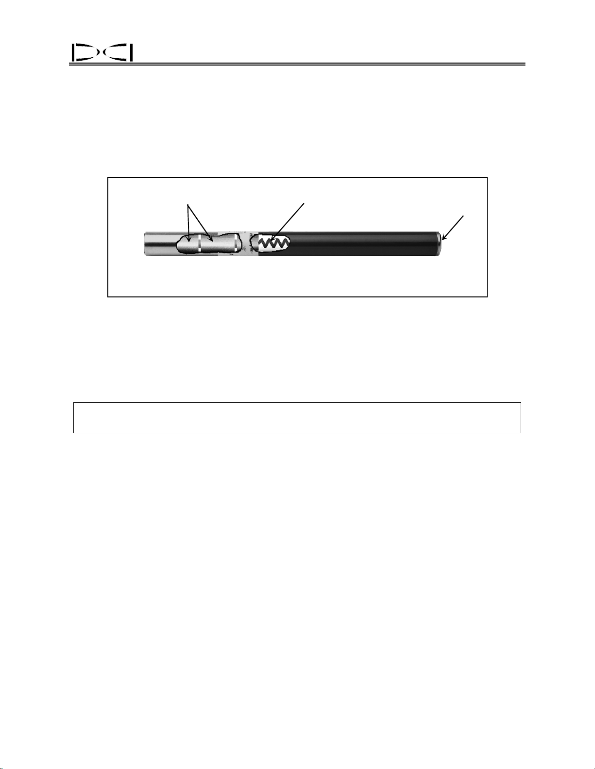
Transmitter
Batteries Antenna
Index Slot
Back
DigiTrak Transmitter
A transmitter (also referred to as a sonde, beacon, or probe) is a device that emits electromagnetic
signals at radio frequencies and fits inside the tool housing. It transmits information regarding its location,
position, and heading. The transmitter emits signals that the receiver “hears” and converts into the
information shown in the three display windows. The range of a transmitter depends upon its type. For
more information, see the DigiTrak Transmitter Specifications table at the end of this section.
NOTE: The range of any transmitter with any DCI receiver is dependent upon the amount of inter-
ference at a job site. The range decreases as interference increases.
Front
How a Transmitter Works
The transmitter emits two types of signals, both at approximately 33 kHz. The first signal is the depth or
signal strength. The second signal sends pitch, roll, and battery and temperature status information. The
pitch/roll signal has a wider bandwidth than the depth signal and occasionally may be more susceptible to
interference. For more information about interference and transmitter signal interruption, see the Signal
Interference Section, the Troubleshooting Section, and “Electrical Interference/Background Noise Check”
in the Signal Interference Section.
With the trigger released, verify that the transmitter is sending adequate pitch and roll information to the
receiver—the top left window of the receiver will flash a squiggle (“~”) every 2.5 seconds. It is important
to wait for two consecutive squiggles with the same pitch and roll information before relying on the information to give any steering commands. Waiting assures confirmation of an accurate reading. As the
transmitter reaches its maximum range, the squiggles will become less frequent than every 2.5 seconds.
For further information on pitch/roll and the squiggle, see the Operational Tests Section (particularly
“Transmitter Tests”).
Transmitter pitch is displayed in percent slope as 1% increments or 0.1% increments (if using a sensitivepitch transmitter) in the top left window of the receiver with the trigger released. For more information see
“Sensitive-Pitch Transmitters” later in this section.
DigiTrak® Mark III Operator’s Manual 19
®
Transmitter
Transmitter roll positions are displayed digitally as a whole number from 1 through 12 in the top right
window with the receiver’s trigger released. The numbers correspond to the hour hand of a clock. At the
12 o’clock position, the transmitter is oriented with the index slot at the top. The tapered or flattened surface of the drill head should be indexed to this position.
Batteries
All DCI transmitters (except the cable transmitter) are powered by C-cell alkaline batteries (see Transmitter Specifications at the end of this section). The long-range transmitters, including the sensitive-pitch
transmitters, have a 4 C-cell option for longer bores. The status of the batteries in the transmitter can be
viewed (in percent life remaining) using the receiver’s display (see “Battery Status Display” below). The
cable transmitter requires an above-ground power supply (see Transmitter Section).
Temperature Display
Transmitter temperature is displayed in degrees Celsius. Every 4°C
increase in the transmitter’s temperature will flash for 2 seconds in the
top right window of the receiver and the remote display. The receiver
will also sound audible tones that increase in intensity as the
transmitter’s temperature increases. When the remote display has a
DataLog module attached, the transmitter’s temperature increase
tones will be heard at the drill. To manually view the temperature of
the transmitter, simply hold in the receiver’s trigger; the temperature
will flash in the top right window. Receivers with pre-5.0 series
firmware will display the temperature in the top right window while the
trigger is held in, but it will not flash. To view the transmitter temperature at the drill, see the Remote Display Section.
+
6 I 9
~
Transmitter Temperature
Display (Flashing)
I
26
22
Battery Status Display
The percent of battery life remaining in the transmitter is displayed in
the top left window for 2 seconds upon releasing a held-in trigger. The
transmitter’s battery status in percent remaining life is displayed as
100, 90, 75, 50, 25, 10, 5, or 0. (The receiver’s battery status in
percent remaining life is also displayed during this 2-second interval in
the top right window as 99, 90, 75, 50, 25, 10, 5, or 0.) If the word
BAT occurs in the top left window when not viewing the transmitter’s
battery status, the transmitter batteries must be replaced.
NOTE: Neither the temperature nor the battery status will
be available until 4 minutes after initial start-up for
receivers with 5.0 series or later firmware.
Transmitter Battery Status
in Percent Remaining Life
905690
BAT
Temperature Overheat
All transmitters have a temperature overheat indicator (temp dot) that has an outer yellow ring with a 1/8inch (3-mm) white dot in the center. This temp dot is located on the stainless-steel front end cap. On
older transmitters, the temp dot is located inside the battery compartment next to the battery terminal.
20 DigiTrak® Mark III Operator’s Manual
 Loading...