


R
Digitrax
Command
Control
UT1 & UT2
LocoNet Utility Throttle Manual
Digitrax, Inc.
450 Cemetery ST #206
Norcross, GA 30071 USA
(770) 441-7992 Fax (770)441-0759
www.digitrax.com
Digitrax Manuals & Instructions are updated periodically.
Please visit www.digitrax.com for the latest version of all manuals.
This manual was updated 06/03.
N
o
c
e
o
t
R
L

1
1.0 UT1 & UT2 Utility Throttle Features & Specifications 3
2.0 Using your UT Throttle 3
2.1 Turning On Track Power 4
2.2 Turning Off Track Power 4
2.3 Running a Locomotive 4
2.3.1 Run An Analog Locomotive on Address "00" 4
2.3.2 Run A DCC Equipped Locomotive 6
3.0 UT1 Throttle Control Panel 7
3.1 General color codes 7
3.2 The Throttle Knob 7
3.3 Direction Toggle Switch 7
3.4 Address Selector Rotary Dials 8
3.5 Status Indicator 8
3.6 Shift Key 8
3.7 Run/Stop Key 8
3.8 ACQ/DISP Key 8
3.9 F0/F3 Key 8
3.10 F1/F4/ON Key 9
3.11 F2/F5/OFF Key 9
3.12 Four Top Row LEDs (Chase Lights) 9
4.0 UT2 Throttle Control Panel 10
4.1 General Color Codes 10
4.2 The Throttle Knob 10
4.3 Direction Toggle Switch 11
4.4 Address Selector Rotary Dials 11
4.5 Status Indicator 11
4.6 PROG/SHIFT Key 11
4.7 Run/Stop Key 11
4.8 ACQ/DISP Key 11
4.9 F0/F3/ADR Key 12
4.10 F1/F4/ON/CV# Key 12
4.11 F2/F5/OFF/CV VAL Key 12
4.12 Four Top Row LEDs (Chase Lights) 12
5.0 UT Throttle: System Modes 12
5.1 UT Throttle Configuration Mode 12
5.1.1 UT Throttle Configuration Options 12
5.1.2 UT Throttle ID Number 13
5.2 Track Power Mode 13
5.3 Walkaround Operation on LocoNet 13
5.4 Stop Mode 14
5.5 Address Mode 14
5.6 UT2 Programming Mode 15
UT1 & UT2 LocoNet Utility Throttle Manual
Table of Contents

5.6.1 Loadable Speed Tables 18
5.7 Status Editing Mode 18
5.8 Switch Mode 18
6.0 Running Trains 19
6.1 Locomotive Speed Control 19
6.2 Locomotive Direction Control 19
6.3 Selecting a Locomotive (Safe Mode) 19
6.4 Selecting A Locomotive (Quik Mode) 20
6.5 Dispatching Locomotives 21
6.6 Controlling Lights & Functions 23
6.6.1 Controlling Functions on Consisted Locos 23
7.0 Troubleshooting 24
7.1 Clean Track 24
7.2 UT Throttle Won't power up when plugged in (LEDs Flicker) 24
7.3 Decoder Won't Respond 24
7.4 Emergency Stop 24
7.5 Mechanical Drive Train Problems 25
8.0 FCC Information 25
9.0 Warranty and Repair Information 25
2
Digitrax, LocoNet and others included in this manual are trademarks
of Digitrax, Inc.
Digitrax, Inc. is not responsible for unintentional errors
or omissions in this document.
©Digitrax, Inc. All Rights Reserved. Printed in USA
UT1 & UT2 LocoNet Utility Throttle Manual
Table of Contents (continued)

1.0 UT1 & UT2 Utility Throttle Features & Specifications
· The UT Throttles are "traditional" hand held DCC throttles. The UT
Throttles are laid out with a single knob for speed control and a simple toggle switch for direction.
· Digitrax LocoNet network forms a simple, reliable interconnect
between all Digitrax Command Control System components using
extremely reliable and convenient gold plated RJ12 6 pin modular
telephone jacks.
· Control up to 98 locomotives (97 DCC & 1 Analog)
· 128 speed step operation!
· Simple locomotive selection using two rotary selectors.
· Control directional lighting & 5 additional function outputs from the
keypad. If you have locomotive equipped with sound, controls for
bell & whistle are on F1 & F2. F2 is a non-latching control that
allows you to sound the horn for as long as the key is held down. F2
can be configured to be non-latching.
· F3 can be configured to be momentary for remote coupler functions,
etc...
· Special "DISPATCH" function to allow consists or 4 digit addresses
to be operated by the UT Throttle.
· "SAFE" mode operation allows smooth pick-up and or release of
trains or locomotives.
· UT1 does not have programming capabilities. UT2 can program
decoder CVs 01-99.
Your success with and enjoyment of our products are very important to
us. After all, this is a hobby and it is FUN!!! Please read this manual carefully before you install your system. We have included lots of
hints and operating ideas based on our experience with the Digitrax
system. If you have questions not covered by this manual please
contact your dealer or Digitrax.
2.0 Using your UT Throttle
For operation, the UT Throttle does not need a battery. The UT Throttle
will remember the last throttle settings after it is unplugged from
LocoNet and will resume when it is plugged back into LocoNet.
Plug the UT Throttle into any LocoNet jack on your LocoNet system
When the UT Throttle is first connected to LocoNet all the LEDs in its
display will blink on and then off again. This means that the throttle
is working and is communicating as it should.
3

2.1 Turning On Track Power
Turn on the track power by pressing and holding the "RUN/STOP" button, then
simultaneously pressing the "ON/F1" button. The command station will beep
once and the "TRACK STATUS" light on the command station will come on.
2.2 Turning Off Track Power
Turn off the track power by pressing and holding the "RUN/STOP" but-
ton, then simultaneously pressing the "OFF/F2"button. The command station will beep once and the "TRACK STATUS" light on the
command station will go off.
2.3 Running a Locomotive
Connect your UT Throttle to any LocoNet jack connected to the command
station in your LocoNet system.
2.3.1 Run An Analog Locomotive on Address "00"
The address "00" is reserved for "Analog" locomotives or any locomotive not
equipped with a decoder.
1. Place a non-decoder equipped locomotive on the track. The locomotive will make a "humming noise", this is the normal sound an analog locomotive will make on a DCC layout.
2. Select the two digit address "00" of the analog locomotive you want
to run using the rotary dial selectors on the UT Throttle. The left
rotary dial selects the "tens" and the right rotary dial selects the
"ones".
3. Press "ACQ/DISP" to select locomotive. The "STATUS" INDICATOR should be a steady green to indicate that you now control that
locomotive.
4. If the "STATUS" INDICATOR is off, the locomotive that you tried
to select is already being controlled by another throttle in the system
and is not available.
5. A red "STATUS" INDICATOR indicates that the direction switch is
not set to the same direction as the locomotive you are trying to
select. Reverse the direction toggle switch and the "STATUS" INDICATOR will turn green.
6. Strobing green "Chase Lights" across the top of the keyboard indicate the throttle speed is higher or lower than the locomotive you
are trying to select. If the LEDs are strobing Left to Right, turn the
throttle knob clockwise until the LEDs stop strobing and the "STATUS" INDICATOR turns green. If the LEDs are strobing Right to
Left, turn the throttle knob counter clockwise until the LEDs stop
strobing and the "STATUS" INDICATOR turns green. NOTE: if the
4

"STATUS" INDICATOR is red then change the direction of the toggle switch.
7. Flipping the toggle switch to the left will make the locomotive go
forward. Flipping the toggle to the right will make the locomotive
go in reverse.
8. Turn the throttle knob clockwise to increase speed and counter
clockwise to decrease the speed. The throttle knob can rotate
approximately. 300 degrees from start to stop.
2.3.2 Run A DCC Equipped Locomotive
Connect your UT Throttle to any LocoNet jack on your LocoNet System.
In order to select a DCC locomotive, you must know its address. All
Digitrax decoders are factory programmed to the default 2 digit
short address "03." If your decoder has not been re-programmed
then select "03" as the address.
1. Select the two digit address "03" of the DCC locomotive you want
to run using the rotary selectors on the UT Throttle. The left rotary
selects the "tens" and the right rotary selects the "ones".
2. Press "ACQ/DISP" to select locomotive. The "STATUS" INDICATOR should be a steady green to indicate that you now control that
locomotive.
3. If the "STATUS" Indicator is dark, the locomotive that you tried to
select is already being controlled by another throttle in the system
and is not available.
4. A red "STATUS" INDICATOR indicates that the direction switch is
not set to the same direction as the locomotive you are trying to
select. Reverse the direction toggle switch and the "STATUS" INDICATOR will turn green.
5. Strobing green "Chase Lights" across the top of the keyboard indicate the throttle speed is higher or lower than the locomotive you
are trying to select. If the LEDs are strobing Left to Right, turn the
throttle knob clockwise until the LEDs stop strobing and the "STATUS" INDICATOR turns green. If the LEDs are strobing Right to
Left, turn the throttle knob counter clockwise until the LEDs stop
strobing and the "STATUS" LED turns green. NOTE: if the "STATUS" INDICATOR is red then change the direction of the toggle
switch.
6. Flipping the toggle switch to the right will make the locomotive go
forward. Flipping the toggle to the left will make the locomotive go
in reverse.
7. Turn the throttle knob clockwise to increase speed and counter
clockwise to decrease the speed. The throttle knob can rotate
approximately. 300 degrees from start to stop.
5

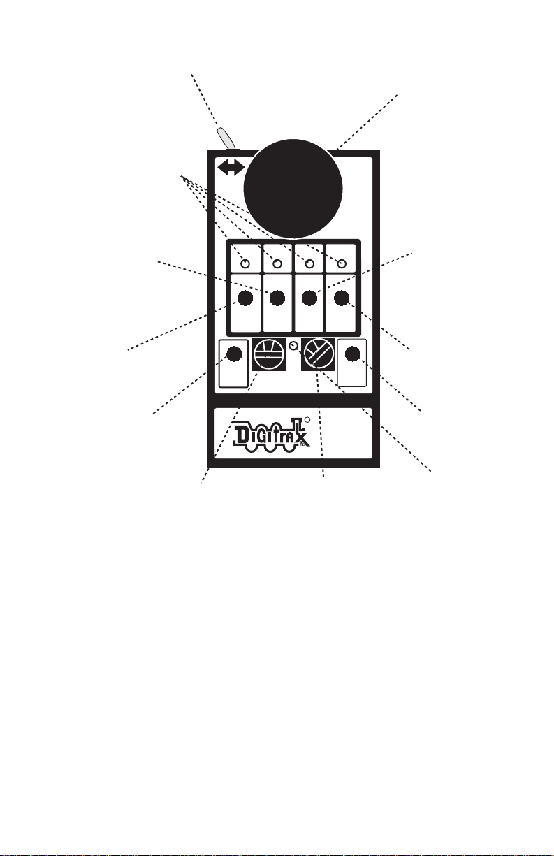
UT1 Throttle Diagram
3.0 UT1 Throttle Control Panel
3.1 General color codes
The UT1 is color coded according to how the keys are used.
The only RED key is Run/Stop. This is so you can't miss it in case of
emergency.
The BLUE keys are used in conjunction with the "SHIFT" key.
3.2 The Throttle Knob
Turn clockwise to increase the speed of your locomotive. Turn counter
clockwise to decrease the speed of your locomotive. There is about
300 degrees of rotation from 0 speed to full throttle.
6
D
irection Toggle Switch
r
.5
Section 3.3
Green LED Indicators
Section 3.12
Throttle Knob
Section 3.2
F1/F4
Section 3.10
F4 F5
F3
F0 F1 F2
ON
F0/F3
Section 3.9
0
SHIFT
LOCO ADDRESS
ST
Shift
Section 3.6
OFF
0
R
ACQ
DISP
RUN
STOP
UT1
F2/F5
Section 3.11
ACQ/DISP
Section 3.8
Run/Stop
Section 3.7
Status
Rotary
Address Selector
Section 3.4
Rotary
Address Selector
Section 3.4
Indicato
Section 3

3.3 Direction Toggle Switch
Flip to the right for forward direction and to the left for reverse direction.
3.4 Address Selector Rotary Dials
Rotate these two selectors to select the two digit address ( 00 to 98 ) of
the locomotive you wish to control. The left selector dials in the 10s
and the Right selector dials in the 1s. Select address "99" to select a
locomotive or consist that has been "DISPATCHED" from another
Digitrax throttle. (See section on dispatched locomotives.)
3.5 Status Indicator
Indicates the status of the UT1.
· Off indicates no locomotive is currently selected.
· Green indicates a locomotive has been successfully selected.
· Red indicates the direction and/or speed are out of correspondence
on a locomotive being selected.
· Blinking orange indicates the UT1 is in "Switch Mode".
3.6 Shift Key
· Press and hold to access F3, F4, F5.
· Press in conjunction with the ACQ button to "Dispatch"
3.7 Run/Stop Key
· Use as emergency stop. When held down will change locomotive
speed to "0". Turn throttle to "0" speed setting to regain control or
press RUN/STOP again.
· RUN/STOP key is used in conjunction with other keys to activate
other throttle functions.
3.8 ACQ/DISP Key
· Press to acquire any locomotive address after the address has been
dialed in with the rotary selectors.
· When address selector reads "99", press "ACQ/DISP" to acquire
locomotive address that has been dispatched by another throttle in
the system.
· If address selector is set to other than "99" press ACQ/DISP and
SHIFT to dispatch the locomotive address to another throttle in the
system.
· Press ACQ/DISP along with RUN/STOP to set Option Switches in
your booster.
3.9 F0/F3 Key
· Press F0 to toggle front and rear headlights on and off.
· Hold "Shift" and press F3 to toggle Function 3 on and off.
7

3.10 F1/F4/ON Key
· Press F1 to toggle Function 1 on and off.
· Hold "Shift" and press F4 to toggle Function 4 on and off.
· Press "RUN/STOP" and "ON" together to turn track power on.
3.11 F2/F5/OFF Key
· Press F2 to toggle Function 2 on and off.
· Hold "Shift" and press F5 to toggle Function 5 on and off.
· Press "RUN/STOP" and "OFF" together to turn track power off.
3.12 Four Top Row LEDs (Chase Lights)
· Indicates function status, lit when on
· All four LEDs strobing left to right means that you need to increase
speed on the throttle knob to complete the selection of a locomotive.
· All four LEDs strobing right to left means that you need to decrease
speed on the throttle knob to complete the selection of a locomotive.
· Indicates CLOSED when in Switch Mode.
· LED above ACQ blinking every 4 seconds indicates that the throttle
is active.
8
UT2 Throttle Diagram
4.0 UT2 Throttle Control Panel
4.1 General Color Codes
The UT2 is color coded according to how the keys are used.
The only RED key is Run/Stop. This is so you can't miss it in case of
emergency.
The BLUE keys are used in conjunction with the "SHIFT" key.
4.2 The Throttle Knob
Turn clockwise to increase the speed of your locomotive. Turn counter
clockwise to decrease the speed of your locomotive. There is about
300 degrees of rotation from 0 speed to full throttle.
L O CO A D DR E S S
S T
F 4F5F 5
F 3
R U N
S T OP
S H IF T
P R OG
A D R
C V #
C V V L
A C Q
D I SP
O P SW
O N
O F F
1 2 8282 8141 4
F 0F1F 1F2F 2
Direction Toggle Switch
9
Section 4.3
Green LED Indicators
Section 4.12
Throttle Knob
Section 4.2
F1/F4
Section 4.10
F0/F3
ADR
Section 4.9
Shift/Program
Section 4.6
CV#
ON
Rotary
Address Selector
Section 4.4
128
F3
F0
ADR
SHIFT
PROG
c
F4
CV#
ON
0
ST
LOCO ADDRESS
CV VL
OPSW
OFF
9
R
ACQ
DISP
RUN
STOP
UT2
Rotary
Address Selector
Section 4.4
F2/F5
CV Value
Section 4.11
Acquire
Dispatch
Option Switch
Section 4.8
Run/Stop
Section 4.7
OFF
Status
Indicator
Section 4.5

4.3 Direction Toggle Switch
Flip to the right for forward direction and to the left for reverse direction.
4.4 Address Selector Rotary Dials
Rotate these two selectors to select the two digit address ( 00 to 98 ) of
the locomotive you wish to control. The left selector dials in the 10s
and the Right selector dials in the 1s. Select address "99" to select a
locomotive or consist that has been "DISPATCHED" from another
Digitrax throttle. (See section on dispatched locomotives.)
4.5 Status Indicator
Indicates the status of the UT2.
· Off indicates no locomotive is currently selected.
· Green indicates a locomotive has been successfully selected.
· Red indicates the direction and/or speed are out of correspondence
on a locomotive being selected.
· Solid orange indicates the UT2 is in Program Mode.
· Blinking orange indicates the UT2 is in "Switch Mode".
4.6 PROG/SHIFT Key
· Press and hold to access F3, F4, F5.
· Press in conjunction with the RUN/STOP key to enter Program
Mode
· Press and hold for 2 seconds then within 5 seconds press either F0,
F1 or F2 to “Status Edit” decoder speed steps to 128, 28, or 14,
4.7 Run/Stop Key
· Use as emergency stop. When held down will change locomotive
speed to "0". Turn throttle to "0" speed setting to regain control or
press RUN/STOP again.
· RUN/STOP key is used in conjunction with other keys to activate
other throttle functions.
4.8 ACQ/DISP Key
· Press to acquire any locomotive address after the address has been
dialed in with the rotary selectors.
· When address selector reads "99", press "ACQ/DISP" to acquire
locomotive address that has been dispatched by another throttle in
the system.
· If address selector is set to other than "99" press ACQ/DISP and
SHIFT to dispatch the locomotive address to another throttle in the
system.
· Press ACQ/DISP along with RUN/STOP to set Option Switches in
your booster.
10

4.9 F0/F3/ADR Key
· Press F0 to toggle front and rear headlights on and off.
· Hold "Shift" and press F3 to toggle Function 3 on and off.
· When in Program Mode, press to set locomotive address.
4.10 F1/F4/ON/CV# Key
· Press F1 to toggle Function 1 on and off.
· Hold "Shift" and press F4 to toggle Function 4 on and off.
· When in Program Mode, press to select CV #.
· Press "RUN/STOP" and "ON" together to turn track power on.
4.11 F2/F5/OFF/CV VAL Key
· Press F2 to toggle Function 2 on and off.
· Hold "Shift" and press F5 to toggle Function 5 on and off.
· When in Program Mode, press to set CV Value.
· Press "RUN/STOP" and "OFF" together to turn track power off.
4.12 Four Top Row LEDs (Chase Lights)
· Indicates function status, lit when on
· All four LEDs strobing left to right means that you need to increase
speed on the throttle knob to complete the selection of a locomotive.
· All four LEDs strobing right to left means that you need to decrease
speed on the throttle knob to complete the selection of a locomotive.
· Indicates CLOSED when in Switch Mode.
· In Status Editing Mode, LED indicates either 128, 28 or 14 speed
steps.
· “c” indicates CLOSED when in OpSw Mode.
· “c” blinking every 4 seconds indicates throttle active.
5.0 UT Throttle: System Modes
5.1 UT Throttle Configuration Mode
The UT Throttle comes from the factory configured with the most com-
mon features enabled as defaults. You can change these features to
suit your particular needs by the following procedure.
5.1.1 UT Throttle Configuration Options
1. Choose the features you want from the chart below. Add up the values of your choices to get the "SETTING" value. Example: 0 (Safe
Mode) + 2 (F2 Toggle on/off) + 0 (F3 toggle on/off) = "SETTING"
of 2.
11

TABLE I
2. With the UT Throttle unplugged from LocoNet, Set the rotary selectors to the proper setting (See Table I).
3. Press and hold the F0 key while you plug the UT Throttle into the
LocoNet network. As soon as the UT Throttle powers up, release the
F0 key. The UT Throttle is now set to the new configuration and
will continue to use this configuration until you change it again. The
UT Throttle will remember this new configuration whether it is
plugged in or not.
5.1.2 UT Throttle ID Number
All UT Throttle throttles come from the factory with the Throttle ID set
to "00". As you add throttles it is a good idea to make each throttle's
ID unique. Use the following procedure to set the ID number.
1. Unplug the UT Throttle from LocoNet.
2. Set the two digit ID number of your choice on the two rotary selectors.
3. Press and hold the "SHIFT/PROG" key and plug back into LocoNet.
4. Release the "SHIFT/PROG" key. The UT Throttle will remember
this number until you decide to change it.
5.2 Track Power Mode
If track power is off, press "RUN/STOP" and "ON" simultaneously to
have the Digitrax command station turn on the track power & go
through power up sequencing. Press "RUN/STOP" and "OFF" to
turn track power off.
5.3 Walkaround Operation on LocoNet
The UT Throttle does not use a battery to maintain its internal memory.
All data is stored in EEPROM. When the UT Throttle is connected
to LocoNet It receives its total power requirements from the network.
NOTE: The UT Throttle draws approximately 15 mA at a minimum
6.8V DC and gets its total power requirements from the network. It may be necessary to supplement the network power
Defaults
Options
0=Safe Mode
1=Quik Mode
0=F2 Momentary
operation
2=F2 Toggles on/off
0=F3 Toggles
on/off
4=F3 Momentary
operation
12

supply, on large networks, when using multiple throttles. This
can be done using Digitrax UP5 Universal Panel(s), to expand
LocoNet, with the battery saver option hooked up.
When a UT Throttle is disconnected from the network it turns off, but all
the settings are retained in EEPROM while you move to a different
part of the layout.. When the UT Throttle is re-connected to the network, it will reselect the locomotive it was previously controlling
with all the previous settings intact.
When a UT Throttle with a selected in-use locomotive is disconnected
from LocoNet, for more than the system purge time (about 200 seconds), the Command Station will purge these in-use locomotives to
the common state so that other throttles can access these locomotives. If the original UT Throttle is reconnected after a purge of its
last in-use locomotives, and no settings have changed on the UT
Throttle, it will start the selection process again and as long as no
one else has selected that locomotive, the UT Throttle will re acquire
it. The designation of locomotives as in-use or common ensures
orderly sharing of locomotives on the layout and increases the system's ability to run more locos at a time.
5.4 Stop Mode
Press "RUN/STOP" for 1 second by itself and the locomotive under con-
trol of your throttle will go to Emergency Stop or "0" speed. There
are two ways to restart your locomotive.
· Turn the throttle knob counter clockwise to "0" speed. If you now
increase the throttle setting, your locomotive will respond normally.
· If you press "RUN/STOP" again, for 1 second, the locomotive will
resume at the speed it was running previously.
Use this only as an Emergency Stop.
5.5 Address Mode
The UT Throttle has two different "Addressing Modes", both of which
are described below. These Modes are selectable during the throttle
configuration process described later.
Safe Mode (Default)
While in "SAFE MODE" the UT Throttle is unable to complete the
selection of an available locomotive unless its present speed and
direction match the settings on the UT Throttle.
1. Select the two digit address "03" of the DCC locomotive you want
to run using the rotary selectors on the UT Throttle. The left rotary
selects the "tens" and the right rotary selects the "ones".
2. Press "ACQ/DISP" to select locomotive. The "STATUS" INDICA-
13

TOR should be a steady green to indicate that you now control that
locomotive.
3. If the "STATUS" INDICATOR is dark, the locomotive that you tried
to select is already being controlled by another throttle in the system
and is not available.
4. A red "STATUS" INDICATOR indicates that the direction switch is
not set to the same direction as the locomotive you are trying to
select. Reverse the direction toggle switch and the "STATUS" INDICATOR will turn green.
5. Strobing green "Chase Lights" across the top of the keyboard indicate the throttle speed is higher or lower than the locomotive you are
trying to select. If the LEDs are strobing Left to Right, turn the
throttle knob clockwise until the LEDs stop strobing and the "STATUS" INDICATOR turns green. If the LEDs are strobing Right to
Left, turn the throttle knob counter clockwise until the LEDs stop
strobing and the "STATUS" INDICATOR turns green. Flipping the
toggle switch to the right will make the locomotive go forward.
Flipping the toggle to the left will make the locomotive go in
reverse.
6. Turn the throttle knob clockwise to increase speed and counter
clockwise to decrease the speed. The throttle knob can rotate
approximately. 300 degrees from start to stop.
Quik Mode
While in "QUIK MODE" the UT Throttle is able to select an available
locomotive regardless of its present speed and direction
1. Select the two digit address "03" of the DCC locomotive you want
to run using the rotary selectors on the UT Throttle. The left rotary
selects the "tens" and the right rotary selects the "ones".
2. Press "ACQ/DISP" to select locomotive. The "STATUS" INDICATOR should be a steady green to indicate that you now control that
locomotive.
3. If the "STATUS" INDICATOR is dark, the locomotive that you tried
to select is already being controlled by another throttle in the system
and is not available.
While in "QUIK MODE" the UT Throttle is able to select an avail-
able locomotive regardless of its present speed and direction.
The selected locomotive will change direction and or speed to
match the current settings on the UT Throttle. Care should be
taken to insure that the UT Throttle is at a comparable speed
setting and direction before selecting a locomotive.
5.6 UT2 Programming Mode
The UT1 has no programming ability. To program decoders use a system
14

throttle such as a UT2 or a DT100 series throttle.
To use the UT2 to program a decoder :
1. Press and hold the RUN/STOP key and the PROG key. The STATUS
INDICATOR will change to steady orange indicating that the UT2 is
in Program Mode.
2. Place the loco you wish to program on an isolated programming
track.
3. Make sure the command station is set up for programming only to the
programming track so that you don’t program all the decoders on
you layout at the same time.
Set the Decoder’s Address:
1. Set the rotary selectors to the desired address (01-99).
2. Press the ADR key to set the decoder to the selected address.
Set other Configuration Variables (CVs):
1. Set the roaary selectors to the CV number that you want to program.
2. Press the F1/F4/CV# key.
3. Set the rotary selectors to the value you want to program into the
selected CV.
4. Press the F2/f /CV VAL key to program the value selected into the
CV number selected.
5. To change additional CVs repeat steps 1-4 as many times as necessary to complete the programming.
To return to regular operations after programming:
1. Press the RUN/STOP and PROG keys together.
2. Press the RUN/STOP and ON Keys to turn track power back on. The
Status INDICATOR will blink orange every 4 seconds indicating
that you are in Run Mode again.
15

Table III: Config uration Register Values:
These are some of the common values used in the
Configuration register
(CV #29) and th eir meaning.
Value in
CV29
Meaning to Decoder
Decimal
value
Speed Steps
(Std or Adv)
Analog
Conversion
00
14 (Standard Mode)
No
02
28/128 (Advanced
Mode)
No
04
14 (Standard Mode)
Yes
06
28/128 (Advanced
Mode)
Yes
07
28/128 (Advanced
Mode)
normal direction
reversed
(FX Decoders only)
Yes
22
Enable Loadable
Speed Table
Yes
Table II: Most Commonly Used CVs
CV #
Used For
Value range
Ad(01)
Loco Address
0-98 decimal
02
Start Voltage
(Vstart)
0-99 decimal
03
Acceleration rate
0-99 decimal
04
Deceleration
0-99 decimal
06
Mid-point
Voltage (Vmid)
0-99 decimal
29
Configuration
Register
See Table III
16

5.6.1 Loadable Speed Tables
The UT2 throttle is limited to programming two digit numbers.
Loadable Speed Tables require CV values anywhere from 00 to 127,
because of this the UT2 is not able to adequately program Loadable
Speed Tables. We recommend using an Advanced LocoNet Throttle
such as the DT100, DT200, DT300 or DT400 to program loadable
speed tables.
5.7 Status Editing Mode
If you have a decoder that does not support 128 or 28 speed step opera-
tion, you will need to tell the command station by editing the status
of that decoder before running it with your Digitrax system.
To Status Edit using a UT2:
1. Select the decoder you want to status edit on your UT2 throttle.
2. Press and release the PROG/SHIFT key.
3. For the next 5 seconds one of the top row of LEDs will blink, indicating the speed step setting the command station is currently sending
to this decoder. For example, if the LED under 128 is blinking, the
command station is sending commands to he decoder in 128 speed
steps.
4. To change the speed step setting, press the F0 Key to set the speed
step setting to 128, F1 to set the speed step setting to 28 or F2 to set
the speed step setting to 14. You must do this within the 5 second
time period or the UT2 will automatically exit status edit mode. If
this happens, press and release the PROG/SHIFT Key again to begin
status edit mode again.
5.8 Switch Mode
Turnout Control
The UT Throttle can be used to throw turnouts on your layout if they are
connected to a stationary decoder such as a Digitrax DS54.
1. Press the "RUN/STOP" and the "ACQ" buttons at the same time to
activate "Switch" Mode.
2. Use the two rotary selectors on the UT Throttle to select the turnout
address to throw or close (With the UT Throttle you are limited to a
two digit turnout address).
3. The LED above "ACQ" will light if the last known state of the
turnout selected is the "closed" position.
4. Press "ACQ" to throw and close the turnout.
5. The LED above "ACQ" will be dark if the last known state of the
turnout selected is the "thrown" position.
17

6. If the LED above "ACQ" flashes on and off, the turnout state is
unknown.
7. Return the rotary selector switches to the locomotive address before
exiting "Switch Mode". If the locomotive address is not correct the
locomotive will be released.
8. Press "RUN/STOP" and "ACQ" at the same time to return to normal
operation.
While in "Switch" Mode, you can still control the speed and direc-
tion of your locomotive. Functions will also operate normally
while in "switch" Mode.
6.0 Running Trains
6.1 Locomotive Speed Control
To control the speed of a locomotive, just turn the Throttle Knob clock-
wise to increase speed and counter clockwise to decrease speed. The
knob has approximately. 300 degrees travel from minimum. or zero
throttle to full throttle.
6.2 Locomotive Direction Control
To change the direction of a locomotive, just move the direction toggle
switch to the right for forward direction and to the left for reverse
direction.
If the decoder has momentum, CV 03 and CV 04 set to a value above
zero, then reverse the direction while the train is moving, and the
locomotive will slow down at the programmed deceleration rate,
stop and accelerate again at the programmed acceleration rate in the
opposite direction.
6.3 Selecting a Locomotive (Safe Mode)
1. Connect the UT Throttle to LocoNet.
2. To select a locomotive, dial in the two digit address ( 00 to 98 ) of
the locomotive you wish to control using the two rotary selector
switches. The right selector dials in the 10s and the left selector dials
in the 1s. Select address "99" to select a locomotive or consist that
has been "DISPATCHED" from another Digitrax throttle. (see section on Dispatched locomotives).
3. After selecting the address, press "ACQ/DISP" once to finish the
selection. If "ACQ/DISP" is pressed a second time the locomotive
will be returned to the system again. Pressing"ACQ/DISP" again,
etc.
a. If the UT Throttle is in “SAFE MODE” (default) and the loco-
18

motive you have selected is available and the speed and direction
match the UT Throttle, the “STATUS” INDICATOR will light a
solid green. You will have control of the locomotive.
b. If the “STATUS” INDICATOR lights red, the direction switch is
reversed. Flip the reverse switch to the other direction, the “STATUS” INDICATOR will light solid green.
c. If the four top LEDs are strobing from left to tight or right to left,
this indicates a speed mismatch between the speed setting on the UT
Throttle throttle and the actual speed of the locomotive. Turn the
throttle knob in the direction of the strobing LEDs until the “STATUS” INDICATOR turns green and the top LEDs go off indicating
that the throttle speed is now matched to the locomotive’s actual
speed..
4. If the "STATUS" INDICATOR does not light at all when the
address is dialed in, that locomotive is already assigned to another
throttle and is not available.
6.4 Selecting A Locomotive (Quik Mode)
1. Connect the UT Throttle to LocoNet.
2. To select a locomotive, dial in the two digit address ( 00 to 98 ) of
the locomotive you wish to control using the two rotary selector
switches. The right selector dials in the 10s and the left selector dials
in the 1s. Select address "99" to select a locomotive or consist that
has been "DISPATCHED" from another Digitrax throttle. (see section on Dispatched locomotives).
3. After selecting the address, press "ACQ/DISP" once to finish the
selection. If "ACQ/DISP" is pressed a second time the locomotive
will be returned to the system again. Pressing"ACQ/DISP" again
will reselect again.
4. If the UT Throttle is in "QUIK MODE" and the locomotive you
have selected is available, the "STATUS" INDICATOR will light a
solid green.
The selected locomotive will immediately change direction and or
speed if the current settings on the UT Throttle don't match the
locomotive. Care should be taken to insure that the UT Throttle
is at a comparable speed setting and direction before selecting a
locomotive when in QUIK MODE".
5. If the "STATUS" INDICATOR does not light at all when the address
is dialed in, that locomotive is already assigned to another throttle
and is not available.
19

6.5 Dispatching Locomotives
Dispatching is a special feature incorporated into the LocoNet "lan-
guage" to meet the needs of clubs and serious operators that wish to
enforce a strict discipline in how engineers access locomotives. An
example would be having a Superintendent of motive power making
all the locomotive assignments. This also allows the UT Throttle to
run 4 digit addresses and consists made up on other throttles in the
system.
To dispatch a locomotive using a the UT Throttle, simply press the
"ACQ/DISP" and the "SHIFT" buttons together and the locomotive
or consist currently being controlled will be released to the system
and also specially marked as a "Dispatched" locomotive as apposed
to just releasing it to the system.
This specially marked Dispatch locomotive can be requested and
acquired by any UT Throttle using the "99" address on the address
selectors.
Note: The same care should be taken when acquiring a "DIS-
PATCHED" locomotive as when selecting from scratch.
This specially marked Dispatch locomotive can also be requested and
acquired by any BT2 "Buddy Throttle." BT2s have no address
selection capability of their own.
The BT2 that acquires the dispatched locomotive/consist will pick-up the
train in exactly the state it was in when it was initially dispatched,
i.e., if the unit was moving with lights on, it will be acquired with no
speed change and continue with lights on until the acquiring BT2
commands a new setting.
The TOP or control locomotive in a consist or MU lash up can be
Dispatched to pass control of the entire consist .
There is only one Dispatch marked locomotive in the system at a
time. Any throttle can select this dispatched address since it is
“common” to all devices in the system. If another locomotive is
dispatched, it will replace the last locomotive in the dispatch slot.
20

UT Throttle Address Selection Flow Chart
21
Adjust Speed Knob
L R Slow Down
L R Speed Up
If TOP 4 LED's strobe
SAFE MODE
is RED
If STATUS LED
Flip Reverse Switch
R
STATUS LED
RUN
solid "RED"
LOCOMOTIVE
=
G
STATUS LED
solid "GREEN"
QUIK MODE
SHIFT
+
DISP
ACQ
to "COMMON"
RELEASE LOCOMOTIVE
DISP
ACQ
"DISPATCH" ADDRESSED LOCOMOTIVE to "COMMON"
NOT
LOCOMOTIVE
AVAILABLE
R
STATUS LED
"DARK"
ACQ
DESIRED
ADDRESS
OLD
ADDRESS
DISP
ACQUIRE
LOCOMOTIVE
2
4
USER
CHANGES
6
6

6.6 Controlling Lights & Functions
The UT Throttle has 3 function buttons. Each of these buttons controls 2
functions. F0 thru F2 are controlled by just pressing the appropriate
button. The function will toggle on and off each time a button is
pressed. F2 will only stay on as long as the button is held down, this
lets you control whistles and horns when using sound equipped locomotives.
To access F3 thru F5 press the "SHIFT" button at the same time as the
function buttons. F3 thru F5 will toggle on and off each time a button is pressed.
Note that for proper light operation, you must be sure that the
decoder’s speed steps match the speed steps sent by the
Command Station. If you are using a Digitrax or other
Advanced capability decoder, we recommend it be programmed
to the 128 speed step (default) mode or 28 step mode.
6.6.1 Controlling Functions on Consisted Locos
All locomotives in a "BASIC" consist (all locos the same address) will
respond to any function commands issued. F0 will turn the headlights of all the locomotives in the consist on and off. The other
functions will work the same way.
If the UT Throttle is controlling a consist that was made up using
UniVersal consisting with a DT100 and then "Dispatched " to the
UT Throttle, each locomotive in the consist can have its headlight
and functions controlled independently as long as the consisted
locomotives are using 2 digit addressing.
Select the 2 digit address of the locomotive in the consist using the
address selectors. Press "ACQ/DISP", the "STATUS" light will blink
green if a consisted locomotive, other than the TOP or controlling
locomotive address, is selected. Press the appropriate function button
to control the desired function in the consisted locomotive.
Note: The throttle and direction controls will not work while the
"STATUS" INDICATOR is blinking green. To regain control of
the consist, return the address selectors to the TOP or controlling locomotive address and press "ACQ/DISP", The "STATUS" INDICATOR will turn to a steady green, speed and direction control will return for the consist.
22

6.7 Consisting Operations
The UT Throttles will run any consist you have set up with other LocoNet
throttles in your system as long as the address is 01-98 or if you run the consist
as a 4 digit address on 99.
When you are using a UT2 throttle for programming, you will only be able to
access basic consisting. In this case, to run more than one powered loco in a
multiple unit lash up, simply place all the units together on the programming
track and program them with the same address. They will all operate on the
address you set. If you want to have one or more locos run “backwards,” as is
prototypical in some situations, you can program them by setting CV29 so that
the normal direction of travel of the loco/s is reversed (See Table III). If your
decoder does not support this feature, you can also re-wire the motors in the
locos you want to run backwards so that they permanently run in “reverse.”
7.0 Troubleshooting
7.1 Clean Track
The majority of intermittent operation faults can be traced to bad connec-
tions and poor or noisy wheel pickups on locomotives. Check track
cleanliness and quality of wheel pickups. The DCC digital packet
communication strategy performs exceptionally well in a less than
perfect environment, and will often mask bad connections until they
are really impossible to work with!
7.2 UT Throttle Won't power up when plugged in (LEDs Flicker)
Voltage on LocoNet is dropping below 6.8V DC as the UT Throttle pow-
ers up. If you are using UP5 Universal Panels to extend the LocoNet
network, hook up the battery saver option using an external 12V DC
power supply.
7.3 Decoder Won't Respond
If you cannot figure out what a locomotive is doing or "who" it is by
address, do not panic! Just reprogram the locomotive. If the decoder
is damaged, all is not lost, it can be repaired. See the Warranty section for details.
7.4 Emergency Stop
If the layout starts to "get away" on you, either PRESS "RUN/STOP" or,
turn the track power to "SLEEP" on the command station. Either
way will give you a chance to regain your composure, and you will
be able to rejoin the contest.
23

7.5 Mechanical Drive Train Problems
Pay attention to the mechanical drive train and free movement of the
locomotive wheel sets. This is especially important with inexpensive
locomotives. Using Digitrax decoders with appropriate programming
settings, you can achieve surprisingly good quality motion, if you
carefully adjust the mechanisms for smooth running.
8.0 FCC Information
Radio or TV Interference: (this information is MANDATED by the FCC)
This equipment has been tested and found to comply with the limits for a Class B digital device, pursuant to part 15 of the FCC rules. These limits are designed to provide
reasonable protection against harmful interference in a residential environment. This
equipment generates, uses and can radiate radio frequency energy and, if not installed
and used in accordance with the instruction manual, may cause harmful interference to
radio communications. However, there is no guarantee that interference will not occur in
a particular installation. If this equipment does cause harmful interference to radio or
television reception, which can be determined by turning the equipment off and on, the
user is encouraged to try to correct the interference by one or more of the following
measures:
-Reorient or relocate the receiving antenna.
-Increase the separation between the equipment and the receiver.
-Connect the equipment into an outlet on a circuit different form that to
which the receiver is connected.
-Consult the dealer or an experienced radio/TV technician for help.
Note that any modifications to the equipment not expressly approved by Digitrax voids
the user's authority to operate under and be in compliance with CFR 47 rules, as administered by the Federal Communication Commission. Digitrax believes any conscientiously installed equipment following guidelines in this manual would be unlikely to
experience RFI problems.
For Canadian Users:
"This digital apparatus does not exceed the Class B limits for Radio noise emission
from digital apparatus set out in the Radio Interference Regulation or the Canadian
Department of Communications."
Le present appariel numerique n emet pas de bruits radio-electriques depassant les limites applicables aux appareils numeriques de la classe B prescrites dans le Reglement
sur le brouillage radioelectrique edicte par le ministere des Communications du Canada.
9.0 Warranty and Repair Information
Digitrax gives a one year guarantee against manufacturing defects on
UT Tthrottles. These units are not user serviceable (opening the case voids
your warranty). If a defect occurs, return the unit to us for service. We will
repair or replace these units at our discretion at no charge to you for one year
from purchase date. Proof of date purchased is required for warranty repair.
This warranty excludes damage due to abuse, such as failure to properly protect against input over current with a fuse or circuit breaker or applying exces-
24

sive input voltage to the unit. We will make any repair needed because of physical damage or electrical abuse at fair and reasonable rates. See
www.digitrax.com for complete warranty information and repair charges for
non-warranty repairs.
All warranties on Digitrax products are limited to refund of purchase
price or repair or replacement of Digitrax products at the sole discretion of
Digitrax. In the event that Digitrax products are not installed or used in accordance with the manufacturer's specifications, any and all warranties either
expressed or implied are void. Except to the extent expressly stated in this section, there are no warranties, express or implied, including but not limited to
any warranties of merchantability or fitness for a particular purpose.
Digitrax, Inc. reserves the right to make changes in design and specifications,
and/or to make additions or improvements in its products without imposing any
obligations upon itself to install these changes, additions or improvements on
products previously manufactured.
25

26
Index
A
ACQ/DISP Key 7, 10
Address "00" 4
Address Mode 13
Address Selection Flow Chart 21
Address Selector Rotary Dials 7, 10
Analog Locomotive 4
B
battery 3, 12
C
Configuration Options 11
D
Decoder Won't Respond 23
Direction Control 18
Direction Toggle Switch 7, 10
Dispatching Locomotives 20
E
Emergency Stop 23
F
F0/F3 Key 7, 11
F1/F4/ON Key 8, 11
F2/F5/OFF Key 8, 11
FCC Information 24
Four Top Row LEDs 8, 11
Functions 22
Functions on Consisted Locos 22
I
ID number 12
intermittent operation 23
L
Lights 22
Locomotive Speed Control 18
LocoNet 3
M
Mechanical Drive Train Problems 24
N
non-decoder equipped locomotive 4
P
Programming 14
Q
Quik Mode 14, 19
R
Run A DCC Equipped Locomotive 5
Run/Stop Key 7, 10
Running a Locomotive 4
S
Safe Mode 11, 13, 18
Selecting a Locomotive 5, 18
Shift Key 7, 10
Status Indicator 4, 5, 7, 10, 13, 14, 19
Stop Mode 13
Switch Mode 17
T
Throttle Knob 6, 9, 18
Track Power 4, 12
Troubleshooting 23
U
UP5 Universal Panel 13
Using your UT Throttle 3
UT Configuration Mode 11
UT1 Won't power up when plugged in
23
W
Walkaround Operation 12
Warranty and Repair 24
 Loading...