

DigiTrak Falcon F2 Quick Start Manual
- 1 -
© 2016 Digital Control Incorporated, Oct
All rights reserved. 402-1021-21-C metric
www.DigiTrak.com
Falcon F2
®
Quick Start Guide
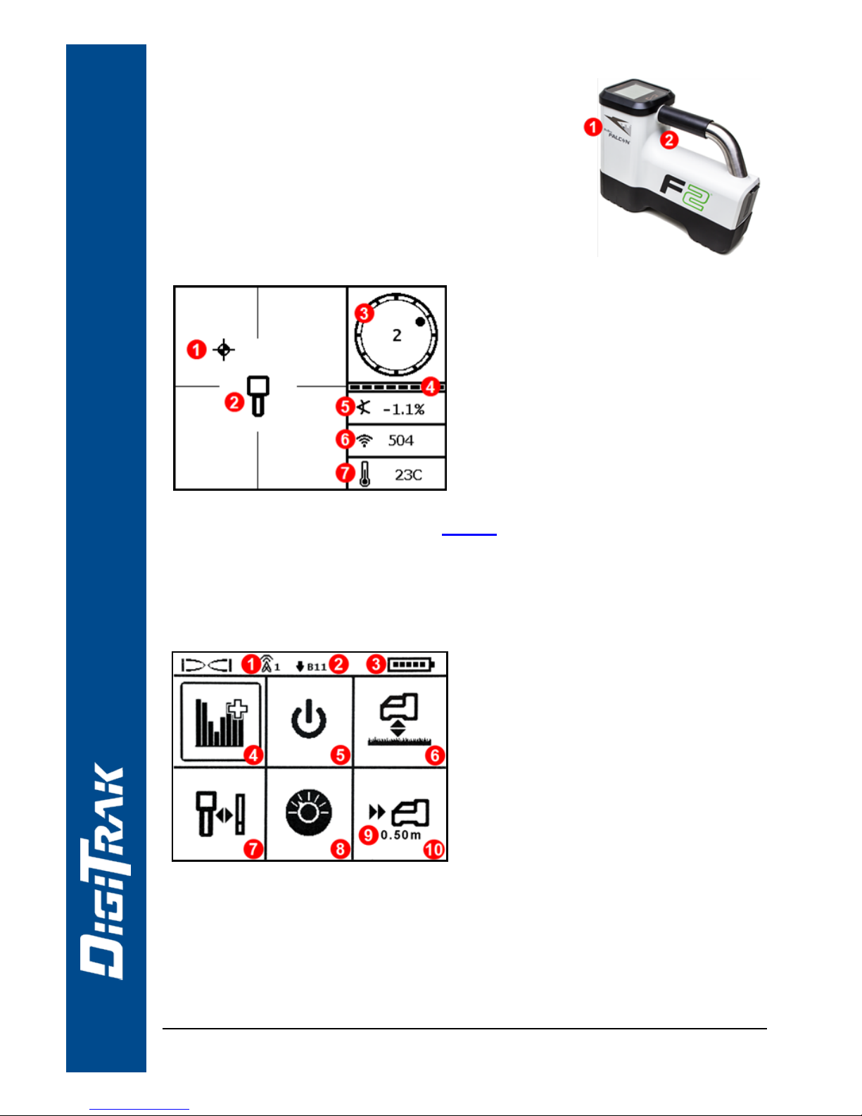
1. IRport2. Trigger
Power On Receiver
1. Installbattery and clicktrigger to power on the
receiver.
2. Ensure the region number in the globe icons on
the startup screen and transmitter match.
3. Click the trigger to reach the Locate screen.
Receiver Locate Screen
1. Locate point (ball)
2. Receiver
3. Roll indicator
4. Roll/pitch update meter
5. Transmitter (Tx) pitch
6. Tx signal strength
7. Tx temperature
Transmitter and receiver must be Paired before data willdisplay(page 3).
Receiver Main Menu
Click to open the Main menu. Clickbetween menu options, hold briefly
and release to select.
1. Telemetry channel
2. Frequency band
3. Battery strength
4. Frequency Optimizer
5. Power off
6. HAG
7. Calibration
8. Settings
9. Target depth
10. Target Steering
For DigiTrak remote displays, see separate manual or QuickStart Guide.
- 2 -
Steps Required Before Drilling
1. Optimize and measure active interference.
2. Select frequency bands.
3. Pair the receiver with the transmitter.
4. Check for background noise.
5. Calibrate both bands.
6. Check Above Ground Range.
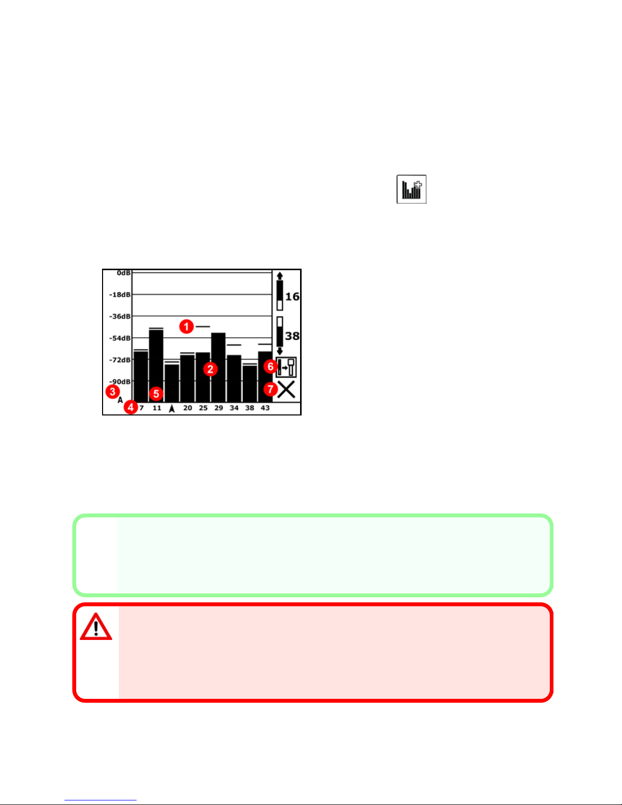
Optimize and Measure Active Interference
1. With the transmitter off, select Frequency Optimizer (FO) from the Main
menu. The FO will show active interference (noise) readings for nine
frequency bands.
1. Maximum noise reading
2. Noise
3. Attenuation in effect
4. Band number
5. Selector
6. Pair
7. Exit
Frequency Optimization Results
2. With the FO results displayed, walkthe receiver along the bore path while
observing the noise readings and mark those points where significant
changes occur.
X
If noise levels rise substantially at any point along the bore, consider selecting
and pairing one band (see next step) that performedwell up to this point. Then
select Exit and restart FO at this point to perform a new scan and select and
pair a second band for use in this higher-interference area.
Your receiver can only detect active interference, not passive interference.
Lower frequency bands tend to perform well despite passive interference.
Middle bands can perform better in deeper bores and may have longer Target
Steering capability. High bands have slightly less signal strength but tend to
offer better performance around active interference such as power lines.
- 3 -
Select Frequency Bands
Up, Down, Cancel
3. Click to move the selector to the band of your choice, hold
briefly to select, then assign as either the Up or Down
band (the band the Tx powers on with when facing Up or
Down). Optionally, set the second band as the opposite.
If the band number you want to use is already displayed atthe right edge of the
screen, select it anyway. Theband you selectnow will beoptimized with
different frequencies than the last time that band was used.
Pair the Receiver with the Transmitter (Tx)
If you assigned two new
bands, both will pair at the
same time, and the
receiver will be set to use
the Down band first.
4. Installtransmitter batteries and endcap; the
increase in FO noise readings shows the Tx
ison.
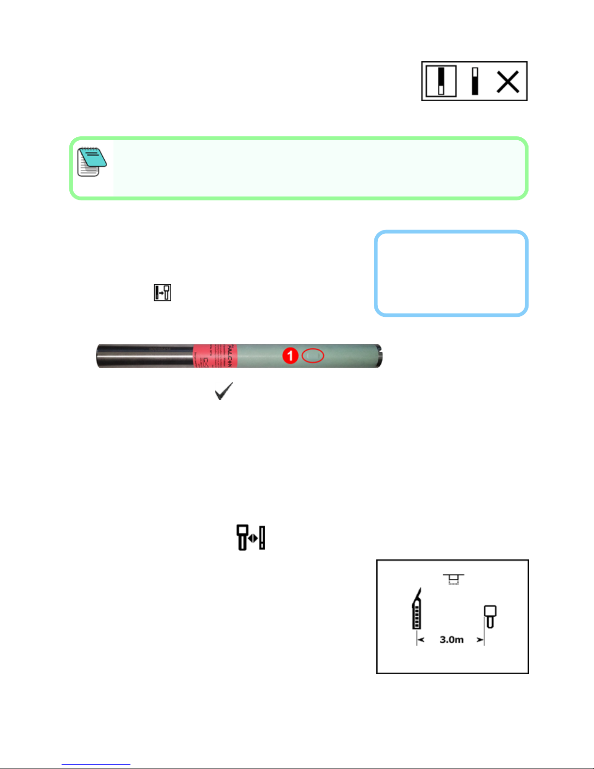
5. Select Pair (flashing).
6. Position the transmitter's infrared (IR) port
within five cm of the receiver's IR port.
1. IR port
7. Select the check mark to complete pairing.
Check for Background Noise
8. Exit to the Locate screen. Have a coworker hold the transmitter beside you at
the approximate distance of the maximum intended depth of the bore. Walk
the bore together in parallel, with the receiver over the bore. Wherever the
data or signal strength becomes unstable or disappears, consider reoptimizing a band in that area (see step 1).
Calibrate Both Bands
Calibration in an interference-free environment is
required after each optimization.
9. Place the Tx in a housing on levelground 3 m
from receiver as shown.
10. From the Main menu, select Calibration,
1PTCAL, and clickto calibrate.
 Loading...