

Page 1
Power On Receiver
1.
Install battery and cli ck trigger to
power on the receiver.
2.
Ensure the region number in the
globe icons on the startup screen and
transmitter match.
3.
Click the trigger to reach the Locate
screen.
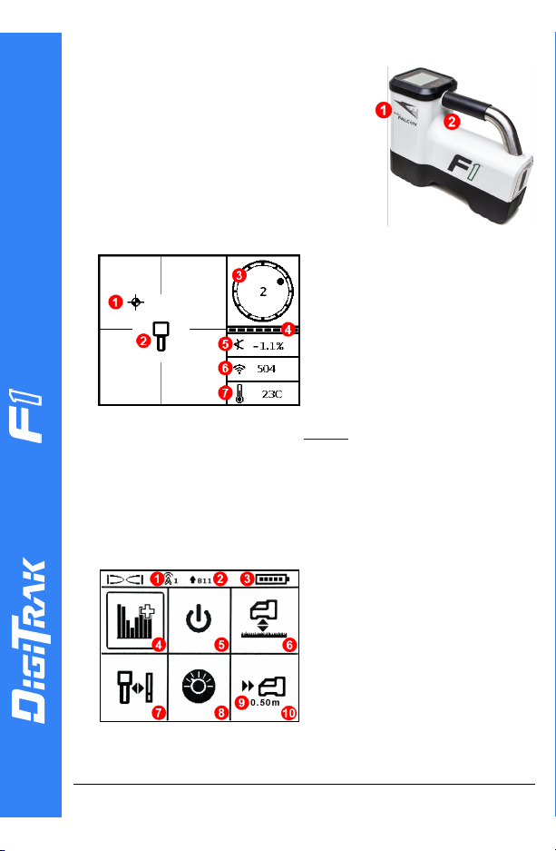
Receiver Locate Screen
1. Locate point (ball)
2. Receiver
3. Rollindicator
4. Roll/pitch update me ter
5. Transmitter (Tx) pitch
6. Txs ignal stren gth
7. Tx temperature
Transmitter and receiver must be Paired before data will display
(page 3). For DigiTrak remote displays, see separate manual or
Quick Start Guide.
1. IRport2. Trigger
Receiver Main Menu
Click to open the Main menu. Click between menu options, hold
briefly and release to select.
Falcon Quick Start Guide
1. Teleme try channe l
2. Frequency band
3. Batte ry strength
4. Fre quency Optimizer
5. Power off
6. HAG
7. Calibration
8. Settings
9. Target depth
10. Target Steering
- 1 -
© 2018 DigitalControlIncorporated, Oct
All rights reserved. 402-1028-21-B metric
www.digital-control.com
Page 2
Steps Required Before Drilling
It is important to run FO for each new project. FO s elects differe nt
frequencies for Band 11 based on the noise at each jobsite.
Your receiver can only detect active interference, not passive
interference. Falcon F1 use s Band 11 in part because frequencies in this
band tend to perform well despite passive inte rference.
1.
Optimi ze and measure active i nterference.
2.
Select frequency Band 11 .
3.
Pair the rec eiver with the transmitter.
4.
Check for background noise.
5.
Calibrate.
6.
Check Above Ground Range.
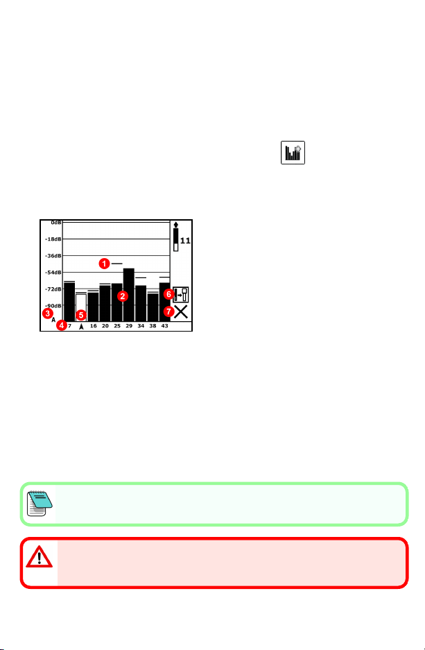
Optimize and Measure Active Interference
1. With the transmitter off, select Frequency Optimizer (FO) from the
Main menu. The FO will show active interference (noise) readings for
Band 11 (and other bands not available on Falcon F 1).
1. Maximum noise reading
2. Noise
3. Attenuation in e ffect
4. Band number
5. Selector
6. Pair
7. Exit
Frequency Optimization Results
2.
With the FO results displayed, walk the receiver along the bore path
while observing the noise readings and mark those points where
significant changes occur. If noise levels rise substantially at any point
along the b ore, consider re-optimizing at this higher-interference
point.
Select Frequency Band 11
3.
Click to move the selector to Band 11, hold briefly to select, then assig n
as the Up band.
- 2 -
Page 3

Pair the Receiver with the Transmitt er (Tx)
This error symbol will display in the roll indicator (Locate scre en) if the
frequency band is not calibrated.
4.
Install transmitter batteries and endcap; the increase in FO noise
readings show the Tx is on.
5. Select Pair (flashing).
6.
Position the transmitter's infrared (IR) port wi thin five cm of the
receiver's IRport.
1. IR port
7.
Select the check mark to complete pairing.
Check for Background Noise
8.
Exit to the Locate screen. Have a coworker hold the transmitter beside
you at the approximate d istance of the maximum intended depth of
the bore. Walk the bore together i n parallel, with the receiver over the
bore. Wherever the data or sig nal strength becomes unstable or
disappears, consider re-optimizing i n that area (see step1).
Calibrate
Calibration in an interference-free envi ronment
is required after each optimizati on.
9.
Place the Tx in a housing on level ground 3m
from receiver as shown.
10. From the Mai n menu, select Calibration,
1PTCAL, and click to calibrate.
- 3 -
Check Above Ground Range (AGR)
11.
Always check AGR with a tape measure to
verify depth readings for Band 11 at various
distances up to the maximum expected bore
depth. Distance readings should be within
±5%.
Page 4

To access the AGR screen later, select Calibration, 1PTCAL, and
- 4 -
wait 15 seconds for the AGR screen.
Settings Menu
Use the Settings menu to set the depth units, p itch units, roll offset, and
telemetry channel. Set the remote di splay to match receiver depth and
pitch settings.
Height-Above-Ground (HAG) Menu
HAG is the distance from the ground to the base of the receiver while it is
held. Setting HAG on the Main menu lets you take accurate below-ground
depth measurements without having to place the receiver on the ground.
Max Mode
Max Mode helps obtain depth/data readings in high-interference areas
when readings are unstable.
l The drill head must remain still during Max Mode readings.
l Hold the trigger at least five seconds to enter Max Mode. Do not
consider the data useful unless the reading is stable before the Max
Mode timer is full.
l Always take three Max Mode readings; all must be consistent.
See the system operator's manual for add itional important information on
the use of this feature.
Signal Attenuation
An A icon may appear on the roll indicator and FO results when the
receiver is attenuating the Tx signal for depths shallower than 3m. This is
normal. See the operator's manual if the signal strength is flashing,
indicating extreme interference.
Watch our DigiTrak®training videos at
www.YouTube.com/DCIKent
Printed:
10/9/2018
Page 5

Basic Locating
1.
Find the FLP and RLP by centering the target ball in the box.
2.
At the FLP, hold trigger for predicted depth reading.
3.
Find the LL by centering the li ne in the box between the FLP and RLP
(see Locate screen on previous page).
4.
View depth by holding the trigger at the LL on the line between the
FLP and RLP.
5. Holding the trigger longer than five seconds enables Max Mode (see
page4).
Transmitter Signal Field Geometry
Level Transmitter
1. Side view
2. RLP: Rear L ocate Point
3. LL: Locate Line
4. FLP: Front Locate Point
Pitched Transmitter
- 5 -
1. Bird's-e ye view
2. RLP
3. LL
4. FLP
5. Drillrig
6. Bore path
7. Side view
FLP and RLP are not equidistant from the LL when the transmitter is
pitched.
Page 6

Bird’s-Eye View on Locate Screen
Receiver Locate Screen,
Appr oaching LL
Actual Position of
Receiver and Tx
Transmitter Depth and Predicted Depth
Trigger held at LL
1. Front or Rear L ocate Point (FLP
or RLP)
2. Bird's-eye view
3. Line-in-the-Box at LL
4. HAG on
5. Max Mode timer
6. Max Mode icon
7. Tx depth
Depth Screen
Trigger held at FLP
1. Re ference indicator
2. Ball-in-the-Box at FLP only
3. Roll/pitch update meter
4. Tx predicted depth
5. Tx battery strength
6. Horizontaldistance between Tx
and FLP
Predicted Depth Screen
- 6 -
1. LL (Tx)
2. Box (re ceiver)
3. Locating ball
4. Tx (underground)
5. Receiver
For detailed information, see your system operator's manual, available at
www.digital-control.com. If you have ques tions, contact your regional DCI office
or U.S.Customer Service at1.425.251.0559.
 Loading...