

Page 1

®
inGround Positioning System (iGPS
Operator’s Manual
®
)
DCI Europe
Kurmainzer Strasse 56
D-97836 Bischbrunn
Germany
Tel +49(0) 9394 990 990
Fax +49(0) 9394 990 999
DCI.Europe@digital-control.com
DIGITAL
CONTROL
INCORPORATED
DCI India
SCO # 259, Sector 44-C
Chandigarh (UT) 160 047
Punjab, India
Tel +91(0) 172 464 0444
Fax +91(0) 172 464 0999
DCI.India@digital-control.com
DCI China
USA Excalibre
2803 Bldg C, 70 Cao Bao Rd
Shanghai P.R.C. 200233
Tel +86(0) 21 6432 5186
Fax +86(0) 21 6432 5187
DCI.China@digital-control.com
19625 62nd Ave. S., Suite B-103
Tel 425 251 0559 / 800 288 3610 Fax 253 395 2800
E-mail DCI@digital-control.com www.digitrak.com
DCI Australia
2/9 Frinton Street
Southport, Queensland 4215
Australia
Tel +61(0) 7 5531 4283
Fax +61(0) 7 5531 2617
DCI.Australia@digital-control.com
Kent, Washington 98032 USA
DCI Russia
420059 Pavlyukhina Street
104, Kazan
Russia
Tel +7 843 277 52 22
Fax +7 843 277 52 22
DCI.Russia@digital-control.com
DCI Headquarters
Page 2

3-1100-00-K (English)
DIGITAL CONTROL INCORPORATED
© 2000-2008 by Digital Control Incorporated. All rights reserved. September 2008 edition.
Trademarks
The DCI logo, CableLink
the-box
®
, Target Steering®, and TensiTrak® are U.S. registered trademarks and DucTrak™, FasTrak™,
®
, DataLog®, DigiTrak®, Eclipse®, iGPS®, Intuitive®, look-ahead®, SST®, target-in-
LT™, SuperCell™, and TeleLock™ are trademarks of Digital Control Incorporated.
Patents
®
The DigiTrak
Eclipse® Locating System is covered by one or more of the following U.S. Patents:
5,337,002; 5,633,589; 5,698,981; 5,757,190; 5,764,062; 5,767,678; 5,878,824; 5,914,602; 5,926,025;
5,933,008; 5,990,682; 5,990,683; 6,002,258; 6,005,532; 6,008,651; 6,014,026; 6,035,951; 6,047,783;
6,057,687; 6,079,506; 6,095,260; 6,160,401; 6,232,780; 6,250,402; 6,396,275; 6,417,666; 6,454,023;
6,457,537; 6,496,008; 6,525,538; 6,559,646; 6,653,837; 6,677,768; 6,693,429; 6,756,783; 6,756,784;
6,768,307; 6,838,882; 6,924,645; 6,954,073; 7,015,697; 7,049,820; 7,061,244. Sale of a DigiTrak
Eclipse
®
Receiver does not convey a lic ense under any patents covering the DigiTrak® Eclipse® Trans-
®
mitter or underground drill housing. Other patents pending.
Limited Warranty
All products manufactured and sold by DCI are subject to the terms of a Limited Warranty. A copy of the
Limited Warranty is included with this manual along with your DigiTrak
®
Eclipse® Locating System; it can
also be obtained by contacting DCI Customer Service, 800-288-3610 or 425-251-0559, or by connecting
to DCI's web site,
www.digitrak.com.
Important Notice
All statements, technical information, and recommendations related to the products of Digital Control
Incorporated (DCI) are based on information believed to be reliable, but the accuracy or completeness
thereof is not warranted. Before utilizing any DCI product, the user should determine the suitability of the
product for its intended use. All statements herein refer to DCI products as delivered by DCI and do not
apply to any user customizations not authorized by DCI nor to any third-party products. Nothing herein
shall constitute any warranty by DCI nor will anything herein be deemed to modify the terms of DCI’s
existing Limited Warranty applicable to all DCI products.
FCC Compliance Statement
This equipment has been tested and found to comply with the limits for a Class B digital device, pursuant
to Part 15 of the Rules of the Federal Communications Commission. These limits are designed to provide
reasonable protection against harmful interference in a horizontal directional drilling installation. This
equipment generates, uses, and can radiate radio frequency energy and, if not installed and used in
accordance with the instructions, may cause harmful interference to radio communications or inaccurate
readings on your DCI locating equipment. However, there is no guarantee that interference will not occur
in a particular installation. If this equipment does cause harmful interference to radio or television reception, which can be determined by turning the equipment off and on, the user is encouraged to try to
correct the interference by one or more of the following measures:
¾ Reorient or relocate the DigiTrak
¾ Increase the separation between the problematic equipment and the DigiTrak
®
Eclipse® Receiver.
®
Eclipse® Receiver.
¾ Connect the equipment into an outlet on a different circuit.
¾ Consult the dealer for help.
Changes or modifications to the DCI equipment not expressly approved and carried out by DCI will void
the user’s Limited Warranty and the FCC’s authorization to operate the equipment.
2 DigiTrak® Eclipse® Operator’s Manual
Page 3

DIGITAL CONTROL INCORPORATED
Table of Contents
SAFETY PRECAUTIONS AND WARNINGS................................................................................................5
INTRODUCTION...........................................................................................................................................9
RECEIVER..................................................................................................................................................11
Power On...............................................................................................................................................11
Toggle and Trigger Switches.................................................................................................................11
Speaker and Audible Tones...................................................................................................................12
Adjusting Screen Contrast.....................................................................................................................12
Main Menu .............................................................................................................................................12
Locate Menu..........................................................................................................................................14
Accessing Locate Mode....................................................................................................................14
Displaying Depth (From the Locate Screen)....................................................................................14
Exiting Locate Mode and Returning to Main Menu ..........................................................................14
Set US Menu..........................................................................................................................................15
Changing the Ultrasonic Setting.......................................................................................................15
Viewing the Ultrasonic Setting..........................................................................................................15
Low Fre/High Fre Menu......................................................................................................................... 16
Frequency Settings...........................................................................................................................16
Changing the Frequency Setting......................................................................................................16
Configure Menu .....................................................................................................................................16
Changing the Telemetry Channel.....................................................................................................18
1-Point Calibration............................................................................................................................19
2-Point Calibration (In-ground Calibration).......................................................................................23
Changing the Grade Mode...............................................................................................................25
Changing the Depth Measurement Mode.........................................................................................25
Cold Screen / Normal Screen...........................................................................................................25
Tele Option A/B ................................................................................................................................26
Locator DL / No Locator DL (Enabling and Disabling DataLog Menus)...........................................26
Set Roll / Unset Roll (Enabling and Disabling Roll Offset Function)................................................26
REMOTE DISPLAY.....................................................................................................................................29
Keypad...................................................................................................................................................29
Power On...............................................................................................................................................29
Speaker and Audible Tones...................................................................................................................30
Adjusting Screen Contrast.....................................................................................................................30
Main Menu .............................................................................................................................................30
Configure Menu .....................................................................................................................................31
Remote Display Screen.........................................................................................................................32
TRANSMITTER...........................................................................................................................................35
Types of Eclipse Transmitters ...............................................................................................................35
Pitch and Roll Information......................................................................................................................36
Batteries.................................................................................................................................................37
Temperature Updates and Overheat Indicator......................................................................................37
Start Up and Frequency Modes.............................................................................................................38
Starting the Standard Eclipse Transmitter........................................................................................38
Starting the Mini Eclipse Transmitter................................................................................................38
Starting the Long-Range Eclipse Transmitter...................................................................................38
Starting the Eclipse Dual-Frequency Transmitter............................................................................. 39
DigiTrak® Eclipse® Operator’s Manual 3
Page 4

DIGITAL CONTROL INCORPORATED
Table of Contents (Continued)
TRANSMITTER (Continued)
Sleep Mode (Automatic Shutoff)............................................................................................................40
Transmitter Housing Requirements.......................................................................................................40
General Transmitter Care Instructions...................................................................................................41
BATTERY CHARGER.................................................................................................................................43
AC/DC Power Setup.............................................................................................................................. 44
Charging a Battery.................................................................................................................................44
LOCATING..................................................................................................................................................47
Locate Points (FLP & RLP) and Locate Line (LL) .................................................................................48
Locating Procedure................................................................................................................................49
THE TARGET STEERING FUNCTION......................................................................................................53
Determining Feasible Target Depth.......................................................................................................53
Programming Target Depth ...................................................................................................................54
Positioning Receiver as Target..............................................................................................................55
Steering to the Target............................................................................................................................56
CABLE SYSTEM.........................................................................................................................................57
Cable System Components...................................................................................................................57
Non-DCI Supplies Required for Operating the Cable System.............................................................. 59
Connecting Power Supply to Power Source and Cable Transmitter....................................................60
Grounding the Cable Transmitter .......................................................................................................... 60
Cable Transmitter On/Off.......................................................................................................................61
Calibrating the Cable Transmitter..........................................................................................................61
Enabling the Roll Offset Function on the Remote Display.....................................................................61
Enabling Roll Offset Function........................................................................................................... 61
Setting Roll Offset Number...............................................................................................................61
Locating Using the Cable System..........................................................................................................62
Viewing Transmitter Depth or Predicted Depth .....................................................................................62
Viewing Status of Cable System Power Source....................................................................................63
Target Steering Function Using the Cable System ...............................................................................63
TROUBLESHOOTING................................................................................................................................65
APPENDIX..................................................................................................................................................67
Depth Increase in Inches (Centimeters) per 6-foot (1.8 meter) Rod ....................................................68
Depth Increase in Inches (Centimeters) per 10-foot (3-meter) Rod.....................................................69
Depth Increase in Inches (Centimeters) per 15-foot (4.6-meter) Rod..................................................70
Percent of Grade to Degree Conversions (0.1% Pitch Transmitters or Sensitive Pitch)......................71
Degree to Percent of Grade Conversions (0.1% Pitch Transmitters)................................................... 72
Calculating Depth Based on Distance Between FLP and RLP ............................................................73
LIMITED WARRANTY
4 DigiTrak® Eclipse® Operator’s Manual
Page 5
DIGITAL CONTROL INCORPORATED
Safety Precautions
and Warnings
Important Note: All operators must read and understand the following Safety Precautions and
Warnings and must review this Operator’s Manual before using the DigiTrak
System.
1 Serious injury and death can result if underground drilling equipment makes contact
with an underground utility such as a high-voltage electrical cable or a natural gas
line.
 Substantial property damage and liabi lity can result if underground drilling equipment
makes contact with an underground utility such as a telephone, cable TV, fiber-optic,
water, or sewer line.
®
Eclipse® Locating
Work slowdowns and cost overruns can occur if drilling operators do not use the
drilling or locating equipment correctly to obtain proper performance.
¾ Directional drilling operators MUST at all times:
•
Understand the safe and proper operation of drilling and locating equipment, including the
use of ground mats and proper grounding procedures.
•
Ensure that all underground utilities have been located, exposed, and marked accurately
prior to drilling.
•
Wear protective safety clothing such as dielectric boots, gloves, hard-hats, high-visibility
vests and safety glasses.
•
Locate and track the drill head accurately and correctly during drilling.
Comply with state and local governmental regulations (e.g., OSHA).
•
Follow all other safety procedures.
•
¾ The DigiTrak Eclipse system cannot be used to locate utilities.
¾ Continued exposure to heat, due to frictional heating of the drill head, can cause inaccurate
information to be displayed and may permanently damage the transmitter.
0 The DigiTrak Eclipse equipment is not explosion-proof and should never be used
near flammable or explosive substances.
DigiTrak® Eclipse® Operator’s Manual 5
Page 6

DIGITAL CONTROL INCORPORATED
Safety Precautions
and Warnings (Continued)
¾ Before each drilling run, test the DigiTrak Eclipse system to confirm that it is operating properly
and check that it is providing accurate drill head location and heading information and accurate
drill head depth, pitch, and roll information with the transmitter inside the drill head.
¾ During drilling, the depth will not be accurate unless:
•
The Eclipse receiver has been properly calibrated and the calibration has been checked for
accuracy so that the receiver shows the correct depth.
•
The drill head has been located correctly and accurately and the receiver is directly above
and parallel to the transmitter in the tool underground or above the front locate point (FLP).
•
The receiver height-above-ground or ultrasonic distance has been set correctly.
¾ Interference can cause inaccuracies in the measurement of depth and loss of pitch, roll, or the
transmitter’s location or heading.
•
Sources of interference include but are not limited to traffic signal loops, invisible dog fences,
cable TV, power lines, fiber-trace lines, metal structures, cathodic protection, telephone lines,
cell phones, transmission towers, conductive earth, salt water, rebar, radio frequencies, and
other unknown sources of interference.
•
Interference with the operation of the remote display may also occur from other sources
operating nearby on the same frequency, such as car rental agencies using their remote
check-in modules, other directional drilling locating equipment, etc.
¾ Carefully review this Operator’s Manual and be sure you always operate the DigiTrak Eclipse
system properly to obtain accurate depth, pitch, roll, and locate points. If you have any questions
about the operation of the DigiTrak System, please call DCI’s Customer Service Department at
425-251-0559 or 800-288-3610.
REMEMBER
If you are having difficulty on the job, call DCI (425-251-0559 or
800-288-3610) and we’ll attempt to help you solve the problem.
6 DigiTrak® Eclipse® Operator’s Manual
Page 7

DIGITAL CONTROL INCORPORATED
Dear Customer:
We would like to thank you for choosing the DigiTrak Eclipse Locating System. We are
proud of the equipment that we have been designing and building in Washington State
since 1990. We believe strongly in providing a unique, high -quality product and standing
behind it with superior customer service and training.
We ask that you take the time to read this entire manual—especially the section on
safety. Also, please fill out the warranty registration and mail it in or fax it to us at 253395-2800. We will put you on the Digital Control mailing list and send you product upgrade information and our FasTrak™ newsletter.
We also ask that you feel free to contact us at the most convenient of our global offices
listed on the front cover if you are experiencing any problems with the equipment or
have any questions regarding its use. Our Customer Service Department is available 24
hours a day, 7 days a week to provide assistance.
As the horizontal directional drilling industry grows, we try to keep an eye on the future
to develop equipment that will make your job faster and easier. We encourage you to
stay current by visiting our web site on the Internet at
call at any of our offices worldwide.
We welcome questions, comments, and ideas.
Digital Control Incorporated
Kent, Washington
September 2008
www.digitrak.com or by giving us a
DigiTrak® Eclipse® Operator’s Manual 7
Page 8

Notes
DIGITAL CONTROL INCORPORATED
8 DigiTrak® Eclipse® Operator’s Manual
Page 9
DIGITAL CONTROL INCORPORATED
Introduction
DigiTrak Eclipse InGround Positioning System
The DigiTrak® Eclipse® inGround Positioning System (iGPS®) brings a new level of locating ease to the
operator of horizontal directional drilling (HDD) locating equipment. The new target-in-the-box
feature and look-ahead
quick verification of mode settings and also the ability to program the intended position of the transmitter
for easier remote steering—this is DCI’s new Target Steering
The DigiTrak Eclipse locating system uses different transmitting frequencies than other DigiTrak locating
systems. These frequencies reduce the effects of interference and increase locating efficien cy.
This manual provides operating instructions for the DigiTrak Eclipse locating system. The information is
presented in sections as follows:
¾ Receiver
¾ Remote Display
¾ Transmitter
¾ Battery Charger
¾ Locating
¾ The Target Steering Function
®
capability enable Intuitive® tracking of the transmitter. The menu options provide
®
feature.
®
locating
DigiTrak® Eclipse® Operator’s Manual 9
Page 10

Introduction
¾ Cable System
¾ Troubleshooting
The first four sections describe and explain how to use the main components: the receiver, the remote
display, the transmitter, and the battery charger. The next two sections give instructions for using the
system for locating and for steering to a target. These are followed by a description of and instructions for
using the Eclipse cable transmitter system. The final section provides quick-reference troubleshooting
information. An appendix is also included with reference tables.
NOTE: Be sure to read carefully the Safety Precautions and Warnings section at the front of this
manual before you use the equipment.
10 DigiTrak® Eclipse® Operator’s Manual
Page 11
DIGITAL CONTROL INCORPORATED
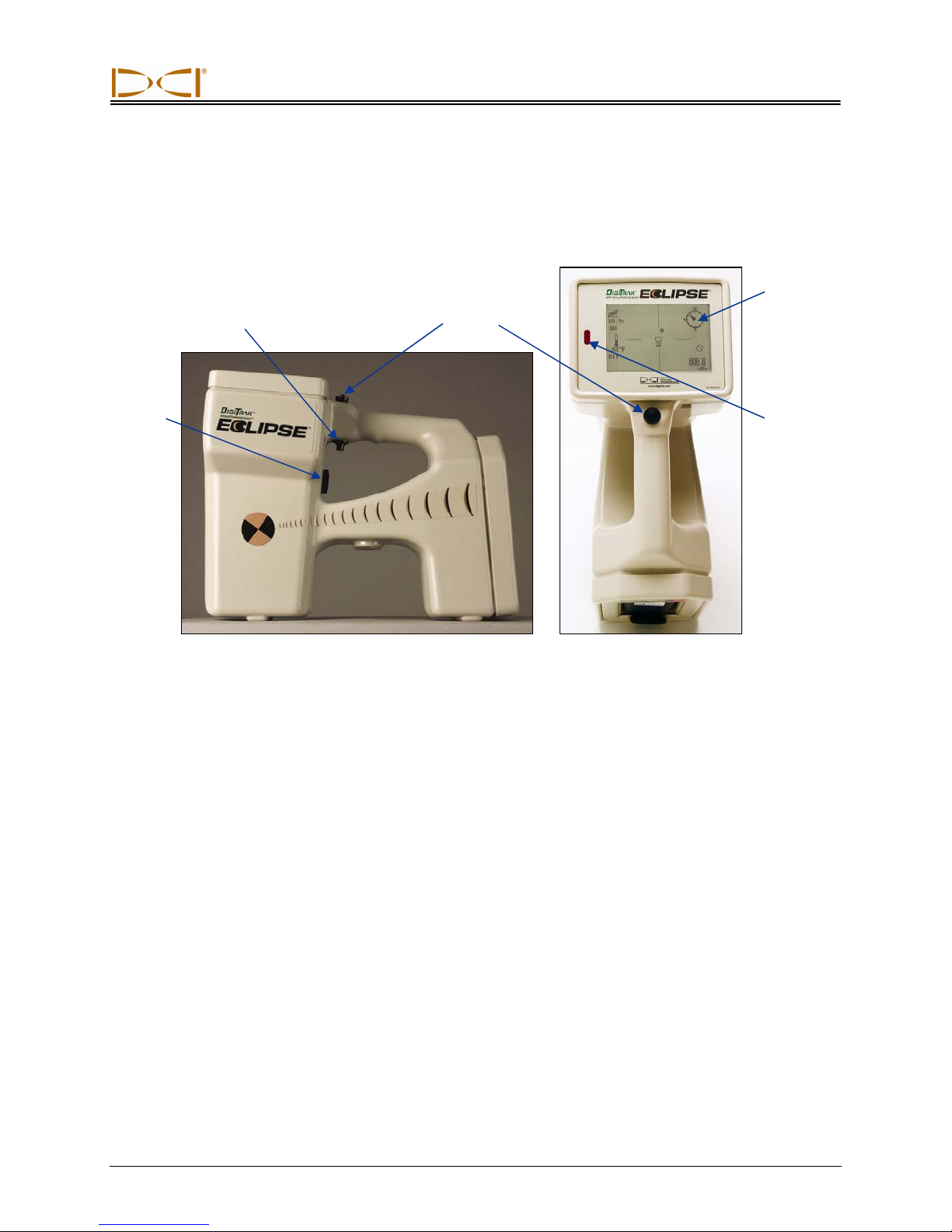
r
Receiver
Trigge
Switch
Speaker
Toggle
Switch
Eclipse Receiver Side View (left) and Top View (right)
Power On
Display
Screen
Infrared
Port
Before turning the Eclipse receiver on, place a rechargeable DCI battery pack (with terminals exposed to
the receiver’s springs) into the battery compartment at the back end of the receiver. Then, click the trigger
under the handle (push it in and release it in less than ½ second) to power up the Eclipse receiver. It may
take a moment for the display to appear.
Toggle and Trigger Switches
The Eclipse receiver has two types of switches for operating the system—a toggle (thumb switch) and a
trigger. The toggle switch is located on top of the handle. It moves in four different directions—left, right,
up, and down. Push the toggle left or right to move the menu arrows on the display to select the desired
menu item. Push the toggle up or down once a menu item is selected to change specific settings, such as
the channel setting.
The trigger switch is located under the handle. It is used to access a menu item once it has been selected
with the toggle. To access the selected menu item, click the trigger (push it in and release it in less than
½ second). When the receiver is in locate mode, the trigger can be held in to view the depth or predicted
depth reading.
DigiTrak® Eclipse® Operator’s Manual 11
Page 12
Receiver
Speaker and Audible Tones
The receiver has a speaker below the trigger area of the handle. The speaker emits warning tones if the
transmitter’s temperature is increasing to indicate that appropriate and immediate attention is required.
Adjusting Screen Contrast
There are two techniques for adjusting the display screen contrast to gradually lighten or darken it. The
receiver must be in locate mode for either technique.
¾ Hold in the trigger while pushing the toggle several times to the right (to lighten) or to the left (to
darken) the display’s contrast.
¾ Push and hold the toggle to the right (to lighten) or to the left (to darken) while clicking the trigger
for the desired contrast.
NOTE: The remote display screen is adjusted in the same way as the receiver except the execute
button serves as the trigger and the toggle arrows work in the same manner as the toggle
switch (see Remote Display section in this manual).
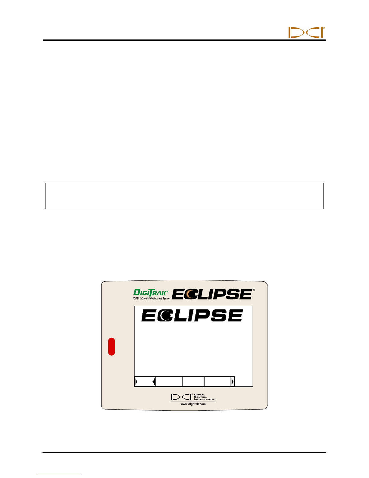
Main Menu
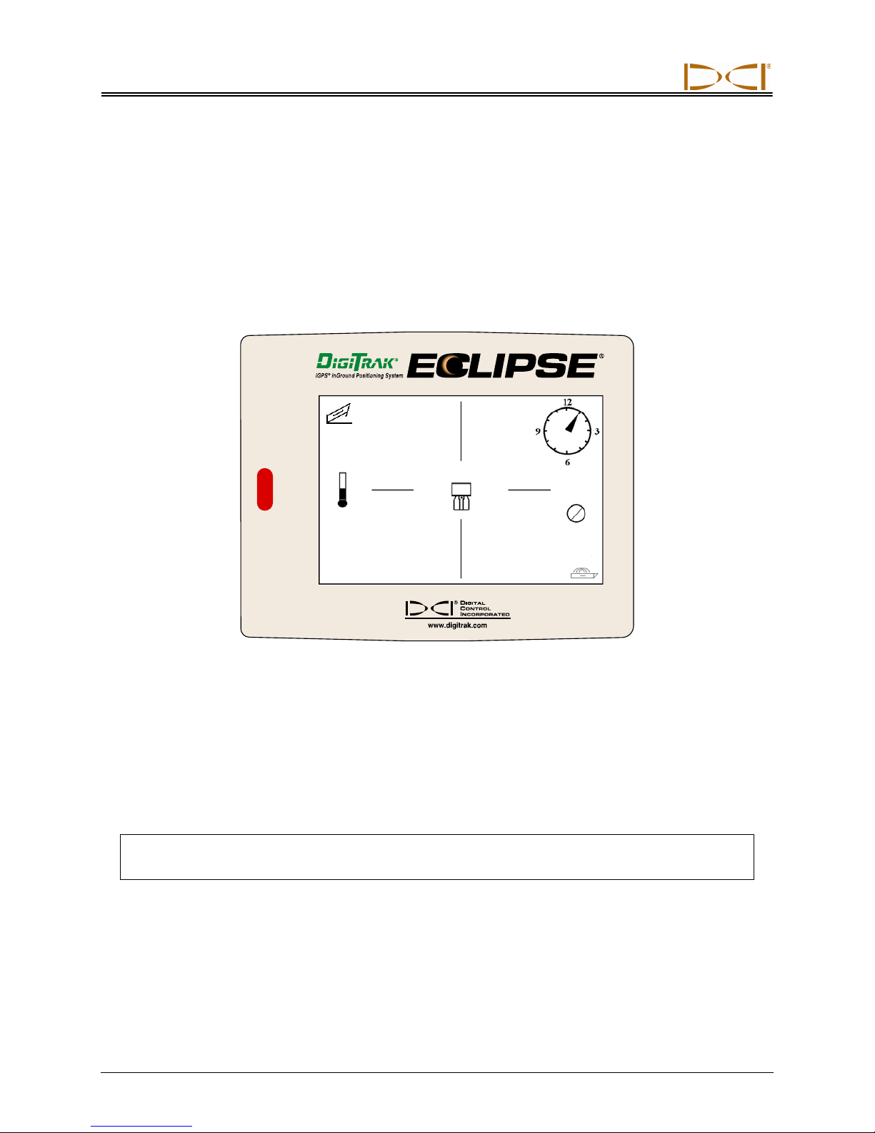
The main system display for the Eclipse software shows the current date/time, the CPU version, and the
DSP version when the unit is first turned on (an example is shown in the figure below). It also shows the
main menu options—Locate, Pow er Off, Set US, Configure, and Low Fre/High Fre (this option can be
viewed by toggling right past Configure). When an item is selected with the toggle, it is indicated by
arrows on the right and left, as shown in the figure below where the Locate menu is selected.
®
CPU Version: r1.1.33.1 Oct 30 2006
Tele Ver: 2.12EDRp DSPVer: 0-4-4
Locate
Power Off
Set US
Configure
12 DigiTrak® Eclipse® Operator’s Manual
Receiver Main Menu Display
Page 13

Receiver
To access one of the main menu items, select the item and then click the trigger once. To select the
Low Fre/High Fre menu option, you must toggle right past the Configure menu. The result for each
menu item is shown in the table below.
Receiver Main Menu Options
Locate
Power Off
Set US
Configure
Low Fre /
High Fre
Displays the locate mode screen (see “Locate Menu” section below). This
screen gives a bird’s-eye view showing the transmitter’s position (see the
Locating section in this manual). It also provides information such as battery
status, temperature, roll, pitch, and signal strength. If the receiver is over the
locate line (LL) and the trigger is held in, the depth is shown; if over the front
locate point (FLP), the predicted depth is shown.
Turns off the Eclipse receiver. Use the toggle to select Power Off, then click
the trigger.
Sets the ultrasonic (US) height setting, which is the height of the receiver
above the ground. See “Set US Menu” section below.
Presents another set of menu options. See the “Configure Menu” section for
an explanation of the Configure menu options.
Changes the receiver’s frequency setting—for use with the dual-frequency
transmitter. See “Low Fre/High Fre Menu” provided below before the
“Configure Menu” section.
NOTE: The frequency setting displayed at the main menu is actually asking if
you want to change to that setting. For example, if you see Low Fre, then the
receiver is set to receive high-frequency signals, and clicking on Low Fre will
change the receiver setting to low frequency. If you see High Fre, then the
receiver is set to receive low-frequency signals, and clicking will change the
setting to high frequency.
For more information on the operation of the dual-frequency transmitter, see
the sections entitled “Starting the Transmitter in Dual- and Single-Frequency
Modes” later in this section and in the Transmitter section.
DigiTrak® Eclipse® Operator’s Manual 13
Page 14
Receiver
Locate Menu
Accessing Locate Mode
• From the main menu screen, push the toggle down once or toggle left to select Locate, then click the
trigger. You will see the locate mode screen.
• From any screen other than the main menu, push down twice on the toggle to advance to the Locate
menu, then click the trigger to enter the locate mode. You will see the locate mode screen.
7.5
%
SH
75°F
CH:B1
411
Locate Mode Screen
Displaying Depth (From the Locate Screen)
1. From the locate mode, hold in the trigger—the depth or predicted depth of the transmitter will be
displayed. You will also see the ultrasonic height setting and the battery status of the receiver and the
transmitter.
2. Release the trigger and you will be returned to the locate mode screen.
NOTE: You will only see depth (or predicted depth) while at the FLP, RLP, or on the LL (see the
Locating section for information on the FLP, RLP, and LL).
Exiting Locate Mode and Returning to Main Menu
From the locate mode, push the toggle down once to return to the main menu.
14 DigiTrak® Eclipse® Operator’s Manual
Page 15
Receiver
Set US Menu
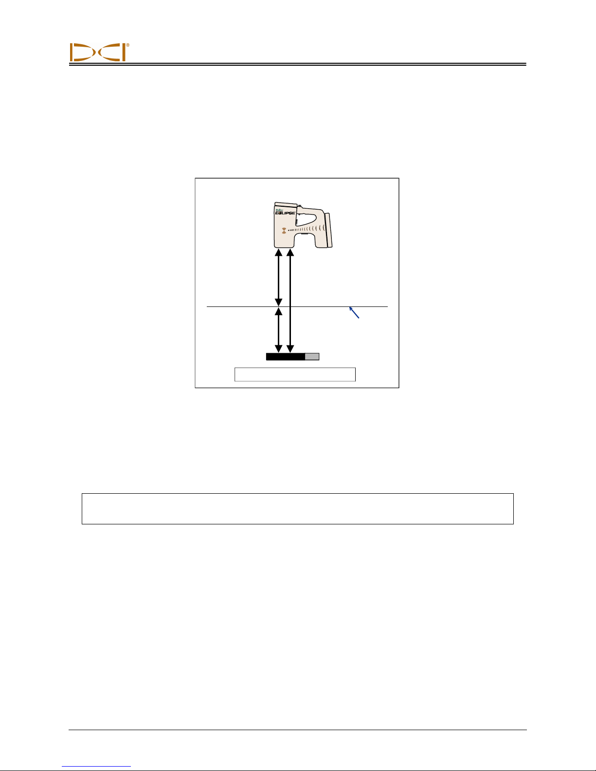
The ultrasonic (US) function measures the receiver’s height above the ground. This distance is then
subtracted from the total magnetic distance from the receiver to the transmitter to determine the depth of
the transmitter below the ground’s surface (see figure below).
Ultrasonic
Measurement
Magnetic
Distance
Depth
Depth = Magnetic – Ultrasonic
Surface of
Ground
Use of Ultrasonic Measurement to Determine Actual Depth
Changing the Ultrasonic Setting
1. Select Set US from the main menu, position the receiver at the desired height above the ground, and
click the trigger one time. The display will show the new ultrasonic setting.
NOTE: You must have the US setting at “0” if are placing the receiver on the ground to take
depth readings.
2. When you are satisfied with the US setting, toggle down once to re turn to the main menu.
Viewing the Ultrasonic Setting
From the locate mode screen, hold in the trigger to view the US setting. The US setting can be viewed at
any time during locating (see Locating section).
DigiTrak® Eclipse® Operator’s Manual 15
Page 16

Receiver
Low Fre/High Fre Menu
Frequency Settings
The frequency menu option will display as either Low Fre (low frequency) or High Fre (high frequency).
If you see Low Fre, you are being asked if you would like to change to the low-frequency setting; this
means the receiver is set to receive high-frequency (12-kHz) signals. If you are running the standard
Eclipse transmitter (black tube), the Eclipse dual-frequency transmitter (lavender tube) in single-high (SH)
or dual-high (DH) mode, or the mini transmitter (gray tube), the receiver should display Low Fre.
If you see High Fre, you are being asked if you would like to change to the high-frequency setting, which
means the receiver is currently set to receive low-frequency signals. If you are running the dual-frequency
transmitter in dual-low (DL) mode, the receiver should display High Fre.
NOTE: The only time you should see High Fre is when you are using the dual-frequency trans-
mitter in dual-low (DL) mode. For additional information, see the Transmitter section.
Changing the Frequency Setting
To change the frequency setting, select the frequency option that is shown, and click the trigger.
Configure Menu
The Configure menu options are listed and described briefly in the table given below. More detailed information and instructions for each menu option follow this listing.
Most of the menu options are presented as a question. For example, if you see ° Grade you are being
asked, “Do you want to measure pitch in degrees?” If the answer is yes, then click the trigger. The menu
item will then change to show % Grade.
16 DigiTrak® Eclipse® Operator’s Manual
Page 17

Receiver
Receiver Configure Menu Options
Tele Ch.
1 Pt. Cal.
2 Pt. Cal.
Target Depth
° Grade /
% Grade
Use Metric /
Use English
IN Only /
FT Only /
FT/IN Units
Changes the telemetry channel setting for the receiver to communicate with the
remote display at the drill (see “Changing the Telemetry Channel” section).
NOTE: The receiver must be set to the same channel as the remote display. The
channel setting is displayed on the lower left side of the locate screen.
Initiates standard calibration procedure used with the transmitter above ground
(see “1-Point Calibration” section).
Initiates calibration procedure used when the transmitter is below ground (see
“2-Point Calibration” section). Should be used with caution.
Allows you to program the transmitter’s depth at a prescribed distance ahead of
its current location. Used for Target Steering function (see The Target Steering
Function section later in this manual).
Changes how the transmitter’s pitch information is displayed (see “Changing the
Grade Mode” section). The pitch can be displayed in percent slope (%) or in
degrees (°).
Changes the depth measurement mode (see “Changing the Depth Measurement
Mode” section). The depth can be displayed in metric units or in three forms of
English units (IN Only, FT Only, or FT/IN Units). When measuring depth in metric
units, the transmitter temperature is displayed in °C; when measuring in English
units, the transmitter temperature is displayed in °F.
Changes the English units for the depth setting. Selecting IN Only will display the
depth in inches and change the menu option to show FT Only. Selecting FT Only
will display the depth in feet and will change the menu option to show FT/IN
Units. Selecting FT/IN Units will display depth in feet and inches and will change
the menu option to show IN Only. All these depth measurement options display
the temperature in °F.
Cold Screen /
Normal Screen
Tele Option A/B
Locator DL /
No Locator DL
Set Roll /
Unset Roll
Code
Exit
DigiTrak® Eclipse® Operator’s Manual 17
Changes from one contrast mode to the other—the screen can have a black
(cold) background or a light (normal) background (see “Cold Scree n / Normal
Screen” section).
Allows communication from a receiver to a remote display when they have
different telemetry systems, such as when one unit has TeleLock™ Technology or
TLT and the other does not (see “Changing the Telemetry Channel” and “Tele
Option A/B” sections).
Enables the DataLog Mapping System menu options so that you can access
DataLog functions from the Eclipse receiver’s main menu screen and store data
when locating (see “Locator DL / No Locator DL” section).
Enables the roll offset function, which allows the transmitter’s roll position to be
compensated to match the tool’s roll position (see “Set Roll / Unset Roll” section).
This menu option is provided for DCI to use for calibration during manufacturing
and for diagnosing problems for repairs.
Returns display to the main menu screen.
Page 18

Receiver
Changing the Telemetry Channel
Telemetry is the wireless communication system used between the receiver and the remote display. The
receiver must be set to the same telemetry channel as the remote display at the drill. There are five
channel settings, including a setting of zero. There are actually only two frequencies—channels 1 and 3
operate at the same frequency, and channels 2 and 4 operate at the same frequency. The zero setting
will not send a signal, and it will also conserve the battery life in the receiver.
To change the telemetry channel:
1. Select Configure from the main menu screen, and click the trigger.
2. Select Tele Ch., and click the trigger. The current channel setting will be displayed.
3. Push the toggle up to advance the channel setting or pull the toggle down to decrease the channel
setting.
NOTE: The receiver must be set to the same channel as the remote display.
4. Once the desired channel is displayed, click the trigger.
5. To exit and return to the main menu, push the toggle down one time.
In addition to the telemetry channel settings, you may need to use the Tele Option A/B function. This
function is part of DCI’s most advanced telemetry system called TeleLock™ Technology (TLT). TLT
extends the telemetry range for longer bores and when the line of sight between the receiver and remote
display is compromised.
You must use the Tele Option A/B function
to Tele Option A) when operating a newer TLT receiver (serial number equal to or greater than EDRR
2690) and an older remote display (serial number less than EDD 2644). If you are operating an older
receiver (serial number less than EDRR 2690) with a newer remote display (serial number equal to or
greater than EDD 2644), then you must use the Tele Option A/B function
Tele Option B (see “Tele Option A/B” later in this section).
When using a newer receiver with TLT and an older remote display without TLT, you must change the
Tele Option A/B setting on the receiver to show Tele Option B:
1. Select Configure from the main menu screen, and click the trigger.
2. Toggle to the right several times to select Tele Option A, and click the trigger. Tele Option B will
now display, and this newer TLT receiver will now communicate with the older remote display.
When using an older receiver without TLT and a newer remote display with TLT, you must change the
Tele Option A/B setting on the remote display to show Tele Option B:
1. Select Configure from the main menu screen, and press the execute button.
2. Press the right arrow several times to select Tele Option A, and press the execute button. Tele
Option B will now display, and this newer TLT remote display will now communicate with the older
receiver.
on the receiver to display Tele Option B (which means it is set
on the remote display to show
You can upgrade your Eclipse receiver and remote display units to have the TLT or enhanced telemetry
function. If you are interested in doing so, please call DCI (425-251-0559 or 800-288-3610) to discuss.
For additional telemetry range, contact DCI to discuss alternate antenna options for your remote display.
18 DigiTrak® Eclipse® Operator’s Manual
Page 19
Receiver
1-Point Calibration
The 1-point calibration procedure is performed with the transmitter in the housing parallel to and 10 ft
(3 m) from the receiver, as described below. DCI does not recommend calibrating every day, but you
should verify the receiver’s depth readings at several locations using a tape measure.
Calibration is necessary prior to first-time use and when any of the following occur:
¾ The transmitter is changed.
¾ The receiver is changed.
¾ The housing/drill tool is changed.
Do not calibrate if:
¾ You are within 10 ft (3 m) of metal structures, such as steel pipe, chain link fence, metal siding,
construction equipment, or automobiles.
¾ The receiver is over rebar or underground utilities.
¾ The receiver is in the vicinity of excessive electrical interference.
¾ The transmitter is not installed into the housing.
¾ The transmitter is not turned on.
1-Point Calibration for Standard, Mini, and Long-Range Transmitters
1. Power up the Eclipse receiver.
2. Toggle right past the Configure menu to verify that you see Low Fre on the main menu screen. If
you see High Fre, then select it, and click the trigger so that the menu option will change to Low Fre.
3. Select Locate, and click the trigger.
4. Power up the standard, mini, or long-range transmitter, and place it into the housing. Verify that the
transmitter is sending proper pitch, roll, battery, and temperature status information.
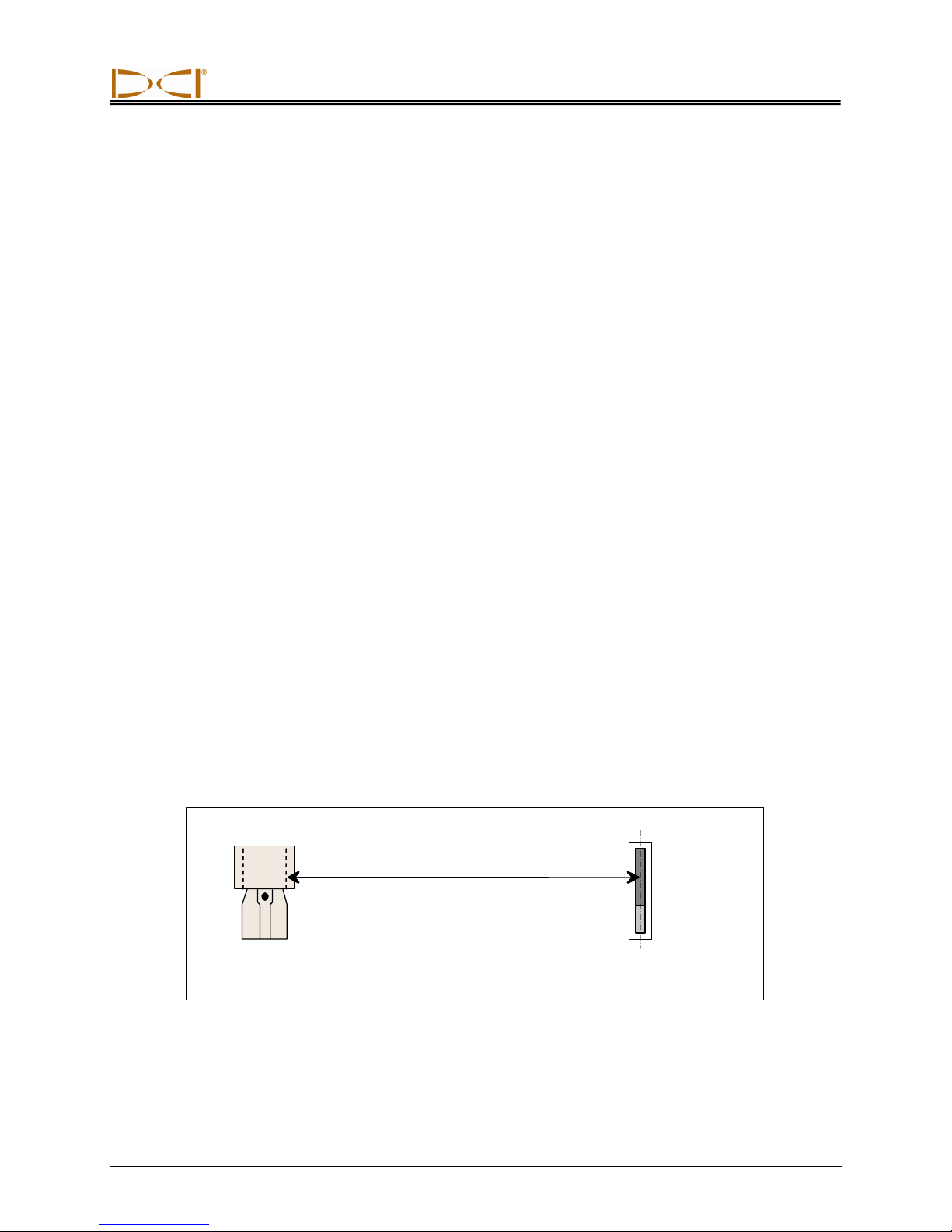
5. With the transmitter in the housing, measure 10 ft (3 m) from the centerline of the transmitter to the
bottom inside edge of the receiver below the display window (see figure)—this should be measured to
the bottom inside edge of the receiver where it meets the ground, not the upper edge at the display,
which is wider.
Eclipse
Transmitter
(Inside
Housing)
Eclipse
Receiver
10 ft (3 m)
Transmitter
Centerline
10-Foot Measurement for 1-Point Calibration
6. Verify that the signal strength at 10 ft (3 m) is approximately 528 for the standard transmitter, 360 to
370 for the mini transmitter, or 620 for the long-range transmitter, and record the value.
7. Select Configure on the main menu display, and click the trigger.
DigiTrak® Eclipse® Operator’s Manual 19
Page 20

Receiver
8. Toggle right to the 1 Pt. Cal. menu item, and click the trigger.
9. Select High Fre Cal, and click the trigger.
10. Toggle to select Y for yes, and click the trigger.
11. Follow the instructions on the display, and click the trigger appropriately.
12. To exit the calibration function and return to the main menu, push the toggle down two times.
13. To access the locate mode, push the toggle to the left until Locate is selected or push the toggle
down one time, and then click the trigger.
14. Verify that the depth reading at 10 ft (3 m) reads 10 ft (3 m); this requires you to go into locate mode
and then hold in the trigger. Check the depth readings in two other locations (e.g., 5 ft/1.5 m and
15 ft/4.6 m).
1-Point Calibration for Eclipse Dual-Frequency Transmitter
To calibrate the Eclipse dual-frequency transmitter (lavender tube), you must first understand how this
type of transmitter works.
The dual-frequency transmitter can be set to transmit in two different modes—dual-frequency mode
(transmitting at 1.5 kHz and 12 kHz) or single-frequency mode (transmitting at 12 kHz). When the dualfrequency transmitter is started up in dual mode, the transmitter is actually sending signals at both
frequencies. The receiver must be set to detect the correct signal or signals being transmitted by the
transmitter.
Each frequency mode offers specific advantages. The dual-frequency mode provides a depth range of
approximately 40 ft (12.2 m) at either the low (1.5 kHz) or high (12 kHz) frequency. This mode is recommended in areas where rebar, wire mesh, or other metal (passive) interference may be encountered. The
single-frequency mode (12 kHz only) provides a depth range of approximately 60 ft (18.3 m). This mode
is intended for use in areas of active interference.
The frequency mode for the transmitter is determined by the orientation of the transmitter at startup, when
the batteries are loaded into the battery compartment. You cannot change the frequency mode of the
dual-frequency Eclipse transmitter when it is downhole.
Starting the transmitter in dual-frequency mode
1. Remove the battery cap, and hold the transmitter vertically with the battery
compartment up and the front end pointing down (see diagram).
2. Load two C-cells (or a SuperCell lithium battery) into the battery compartment with the positive terminal down.
3. Replace the battery cap while rotating the transmitter in this vertica l position.
4. Power up the receiver, and verify that the main menu option shows High
Fre.
5. Select Locate, and click the trigger.
6. You will see DL for Dual Low on the left side of the screen directly above
the thermometer symbol.
7. Verify that the signal strength in the housing at a distance of 10 ft (3 m) is
480 to 490, and record the value.
Loading Batteries
for Dual Mode
20 DigiTrak® Eclipse® Operator’s Manual
Page 21

Receiver
To track the transmitter in dual-high mode, if there is no metal interference:
1. Return to the main menu screen, select High Fre from the main menu, and click the trigger.
2. Select Locate, and click the trigger.
3. You will see DH for Dual High on the left side of the screen, dire ctly above the thermometer symbol.
4. Verify that the signal strength in the housing at a distance of 10 ft (3 m) is 520 to 530, and record the
value.
Starting the transmitter in single-frequency mode
1. Remove the battery cap, and hold the transmitter vertically with the battery
compartment down and the front end pointing up (see diagram).
2. Load two C-cells (or a SuperCell lithium battery) into the battery compartment with the positive terminal entering first.
3. Replace the battery cap while rotating the transmitter in this vertica l position.
4. Power up the receiver, and verify that the main menu option shows Low
Fre.
5. Select Locate, and click the trigger.
6. You will see SH for Single High on the left side of the screen directly above
the thermometer.
7. Verify that the signal strength in the housing at a distance of 10 ft (3 m) is
approximately 565, and record the value.
Loading Batteries
for Single Mode
Calibrating the receiver to the dual-frequency transmitter
in dual-frequency mode
The following instructions will require you to perform two calibration procedures—once for low frequency
and once for high frequency.
1. Start up the dual-frequency transmitter in dual-frequency mode (see instructions above), and place it
in the housing.
2. Power up the receiver.
3. Verify that you see Low Fre on the main menu display (toggle right past Configure). If you see High
Fre, select High Fre, and click the trigger. The display will then change to show Low Fre (which
means the receiver is detecting the transmitter’s high-frequency signal).
4. With the transmitter in the housing, measure 10 ft (3 m) from the centerline of the transmitter to the
bottom inside edge of the receiver below the display window (see figure above entitled “10-Foot
Measurement for 1-Point Calibration”)—this should be measured to the bottom inside edge of the
receiver where it meets the ground, not the upper edge at the display, which is wider.
5. Verify that the signal strength at 10 ft (3 m) is approximately 530 to 540, and record the value (this
requires you to go into locate mode; the signal strength is near the bottom of the screen).
6. Verify that the transmitter is sending proper pitch, roll, battery, and temperature status information
(pitch and roll are viewed from the locate mode screen; battery and temperature status are viewed
from the depth display screen—see the Locating section).
DigiTrak® Eclipse® Operator’s Manual 21
Page 22

Receiver
7. Return to the main menu screen by pushing the toggle down one time.
8. Select Configure on the main menu display, and click the trigger.
9. Select 1 Pt. Cal., and click the trigger.
10. Click the trigger (arrows will have already selected High Fre Cal).
11. Toggle right to select Y for yes, and click the trigger.
12. Follow the instructions on the display, and click the trigger appropriately.
13. Return to the main menu by pushing the toggle down two times.
14. Select Locate, and click the trigger.
15. Place the receiver at 10 ft (3 m) and verify that it reads 10 ft (3 m) by holding in the trigger. Check the
depth readings in two other locations (e.g., 5 ft/1.5 m and 15 ft/4.6 m).
16. You will now calibrate in low frequency. First, select Low Fre from the main menu screen, and click
the trigger.
17. Select Configure, and click the trigger.
18. Select 1 Pt. Cal., and click the trigger.
19. Select Low Fre Cal, and click the trigger
20. Follow the instructions on the display, and click the trigger appropriately.
21. Return to the main menu by pushing the toggle down two times.
22. Select Locate, and click the trigger.
23. Place the receiver at 10 ft (3 m) and verify that it reads 10 ft (3 m) by holding in the trigger. Check the
depth readings in two other locations (e.g., 5 ft/1.5 m and 15 ft/4.6 m).
Calibrating the receiver to the dual-frequency transmitter in single-frequency mode
This procedure is the same as that for calibrating a standard or mini Eclipse transmitter using 1-point
calibration.
1. Start up the dual-frequency transmitter in single-frequency mode (see instructions above), and place
it in the housing. Verify that the transmitter is sending proper pitch, roll, battery, and temperature
status information.
2. Power up the receiver.
3. Select Low Fre on the main menu display (toggle right past Configure), and click the trigger. The
display will then change to show Low Fre (which means the receiver is detecting the transmitter’s
high-frequency signal).
4. With the transmitter in the housing, measure 10 ft (3 m) from the centerline of the transmitter to the
bottom inside edge of the receiver below the display window (see figure above entitled “10-Foot
Measurement for 1-Point Calibration”)—this should be measured to the bottom inside edge of the
receiver where it meets the ground, not the upper edge at the display, which is wider.
5. Verify that the signal strength at 10 ft (3 m) is approximately 565, and record the value (this requires
you to go into locate mode; the signal strength is near the bottom of the screen).
22 DigiTrak® Eclipse® Operator’s Manual
Page 23

Receiver
6. Return to the main menu screen by pushing the toggle down one time.
7. Select Configure on the main menu display, and click the trigger.
8. Select 1 Pt. Cal., and click the trigger.
9. Click the trigger (arrows will have already selected High Fre Cal).
10. Toggle right to select Y for yes, and click the trigger.
11. Follow the instructions on the display, and click the trigger appropriately.
12. Return to the main menu by pushing the toggle down two times.
13. Select Locate, and click the trigger.
14. Place the receiver at 10 ft (3 m) and verify that it reads 10 ft (3 m) by holding in the trigger. Check the
depth readings in two other locations (e.g., 5 ft/1.5 m and 15 ft/4.6 m).
2-Point Calibration (In-ground Calibration)
NOTE: In-ground calibration is rarely needed. If you must calibrate with the transmitter in the
ground, use this procedure with caution.
2-Point Calibration for Standard, Mini, and Long-Range Transmitters
To calibrate the receiver using the 2-point calibration method with the standard, mini, or long-range transmitter in the ground:
1. Verify that you see Low Fre on the main menu screen. If you see High Fre, then select it and click
the trigger so that the menu option will change to Low Fre.
2. Select Configure, and click the trigger.
3. Select 2 Pt. Cal., and click the trigger.
4. Select High Fre Cal, and click the trigger.
5. Toggle to select Y for yes, and click the trigger.
6. Position and stabilize the receiver at least 6 in. (152 mm) above the ground directly over the
transmitter; be sure that the locate line (LL) is aligned with the horizontal cross hairs to ensure you
are directly over the transmitter (refer to the Locating section for details on the LL).
7. Click the trigger when the display instructions in dicate.
8. Raise the receiver at least 30 in. (762 mm) and stabili ze it, then click the trigger.
9. To exit the calibration function and return to the main menu, push the toggle do wn two time s.
DigiTrak® Eclipse® Operator’s Manual 23
Page 24

Receiver
2-Point Calibration for Eclipse Dual-Frequency Transmitter
To calibrate the receiver using the 2-point calibration method with the dual-frequency transmitter in the
ground, you will perform two calibration procedures—the first for low frequency and the second for high
frequency.
The first calibration procedure is for high frequency:
1. Verify that you see Low Fre on the main menu screen. If you see High Fre, then select it and click
the trigger so that the menu option will change to Low Fre.
2. Select Configure, and click the trigger.
3. Select 2 Pt. Cal., and click the trigger.
4. Select High Fre Cal, and click the trigger.
5. Toggle to select Y for yes, and click the trigger.
6. Position and stabilize the receiver at least 6 in. (152 mm) above the ground directly over the
transmitter; be sure that the locate line (LL) is aligned with the horizontal cross hairs to ensure you
are directly over the transmitter (refer to the Locating section for details on the LL).
7. Click the trigger when the display instructions in dicate.
8. Raise the receiver at least 30 in. (762 mm) and stabili ze it, then click the trigger.
9. To exit the calibration function and return to the main menu, push the toggle do wn two time s.
10. Verify depth readings by going into locate mode.
The second calibration procedure is for low frequency:
1. Select Low Fre from the main menu screen, and then click the trigger to change this option to display
High Fre.
2. Select Configure, and click the trigger.
3. Select 2 Pt. Cal., and click the trigger.
4. Select Low Fre Cal, and click the trigger.
5. Toggle to select Y for yes, and click the trigger.
6. Position and stabilize the receiver at least 6 in. (152 mm) above the ground directly over the
transmitter; be sure that the locate line (LL) is aligned with the horizontal cross hairs to ensure you
are directly over the transmitter (refer to the Locating section for details on the LL).
7. Click the trigger when the display instructions in dicate.
8. Raise the receiver at least 30 in. (762 mm) and stabili ze it, then click the trigger.
9. To exit the calibration function and return to the main menu, push the toggle do wn two time s.
10. Verify depth readings by going into locate mode.
24 DigiTrak® Eclipse® Operator’s Manual
Page 25

Receiver
Changing the Grade Mode
The Grade menu item will display as either ° Grade or % Grade. If you see ° Grade, you are being asked
if you would like the pitch measured in degrees. If your answer is yes, click the trigger. This menu option
will then change to display % Grade. If you do not click the trigger when you see ° Grade, you will
continue to measure pitch in percent slope.
To change the grade measurement mode:
1. Select Configure, and click the trigger.
2. Select Grade, and click the trigger. Either ° Grade or % Grade will be displayed, depending on which
measurement mode you are in. If you are measuring in percent slope, you will see ° Grade (giving
you the option to change to degrees); if you are measuring in degrees, then you will see % Grade.
Changing the Depth Measurement Mode
The depth measurement mode can be changed from metric (meters) to English, and in English it can be
displayed in feet and inches (FT/IN Units), in feet only (FT Only), or in inches only (IN Only). Remember,
whichever depth measurement mode option you see, it means you are being asked if you would like to
change to that mode—it does not mean that is the mode you are currently measuring depth in.
To change the depth measurement mode:
1. Select Configure, and click the trigger.
2. Select one of the following:
¾ Use English to display depth measurements in English units
¾ Use Metric to display depth measurements in meters
¾ IN Only to display depth measurements in inches
¾ FT Only to display depth measurements in feet
¾ FT/IN Units to display depth measurements in feet and inches
Cold Screen / Normal Screen
The Cold Screen / Normal Screen menu option allows you to change the screen to have either a Cold
(black) background or a Normal (light) background. Adjusting the screen contrast in increments is also
possible, and is necessary at times, such as when there are changes in temperature or in brightness.
DigiTrak® Eclipse® Operator’s Manual 25
Page 26

Receiver
Tele Option A/B
If you are operating a newer receiver that has the TLT function with an older remote display that does not
have the TLT function, then you must set the receiver’s menu option to display Tele Option B:
1. Select Configure from the main menu screen, and click the trigger.
2. Toggle to the right several times to select Tele Option A, and click the trigger. Tele Option B will
now display (meaning you are set to Tele Option A mode), and your receiver will now communicate
with the older remote display.
If you are operating an older receiver that does not have the TLT function with a newer remote display
that has the TLT function, then you must change the remote display’s setting to show Tele Option B.
1. From the remote display’s main menu screen, select Configure and press the execute button.
2. Press the right arrow several times to select Tele Option A and press the execute button. Tele
Option B will now display (meaning you are set to Tele Option A mode), and this newer remote
display will receive signals from the older receiver.
Locator DL / No Locator DL (Enabling and Disabling DataLog Menus)
If you are using the DataLog Mapping System, then you will need to enable the DataLog menu options so
that you can access DataLog functions from the Eclipse receiver’s main menu screen. With the DataLog
menus enabled, you will automatically begin storing data if you push the toggle up when in locate mode.
See the DataLog Mapping System Operator’s Manual provided with your DataLog system or available at
www.digitrak.com for more information.
To enable the DataLog menu options:
1. Select Configure, and click the trigger.
2. Toggle right several times to select Locator DL, and click the trigger. Your receiver will now display
the DataLog menu options under the Eclipse main menu.
To disable the DataLog menu options, select No Locator DL from the Configure menu options.
Set Roll / Unset Roll (Enabling and Disabling Roll Offset Function)
The Set Roll menu option enables the roll offset function, which is used when the drill bit (tool) and
housing are two separate pieces and their roll positions do not match when the tool is torqued-up to the
housing. The roll offset function is an electronic compensation to match the transmitter’s 12 o’clock
position to the tool’s 12 o’clock position.
26 DigiTrak® Eclipse® Operator’s Manual
Page 27

Receiver
Enabling Roll Offset Function
To enable the roll offset function on the receiver:
1. Power up the receiver.
2. Toggle right to Configure, and click the trigger.
3. Toggle right several times to Set Roll, and click the trigger (note that this menu item will change to
Unset Roll).
The receiver is now ready for you to use the roll offset function.
Setting Roll Offset Number
To set the roll offset number:
1. Torque-up the tool to the housing.
2. Orient the tool to 12 o’clock.
3. Power up the receiver and the transmitter.
4. Place the transmitter inside the housing.
5. From the receiver’s main menu screen, select Locate and click the trigger.
6. Toggle right one time, select Y for yes, and click the trigger. The transmitter’s roll position should now
match the tool’s position, which is 12 o’clock.
The “Roll Offset” number will appear at the top of the receiver’s screen. This number is displayed to
indicate that a compensation for the transmitter’s roll position has occurred. This number will remain in
memory until you change it; therefore, you can calibrate, change the telemetry channel, and replace the
battery without affecting this roll offset number.
:315
°
7.5
%
R
oll Offset
DL
75°F
CH:B1
411
Eclipse Receiver with Roll Offset Displayed
DigiTrak® Eclipse® Operator’s Manual 27
Page 28

Receiver
When the remote display is in remote mode (receiving data from the receiver), you will see the letters
“RO” for roll offset underneath the clock, indicating that a compensation for the transmitter’s roll position
has occurred.
-1.5
%
CH:B1
RO
75°F
Eclipse Remote Display with Roll Offset Displayed
Removing Roll Offset Number
If you want to change the roll offset, you must first remove the “old” roll offset number. The instructions to
remove the roll offset number are below:
1. Power up the receiver and transmitter.
2. From the receiver’s main menu screen, select Locate and click the trigger.
3. Toggle left one time, select Y for yes, and click the trigger.
Disabling the Set Roll Menu Option
If you are using a fixed housing that does not require the roll offset function, you should disable the Set
Roll option so that you do not accidentally change the roll by toggling right while in locate mode. To
disable the Set Roll option:
1. Power up the receiver
2. Toggle right to Configure and click the trigger
3. Toggle right several times to Unset Roll and cli ck the trigger
Note that the menu option will change from Unset Roll to Set Roll.
28 DigiTrak® Eclipse® Operator’s Manual
Page 29

DIGITAL CONTROL INCORPORATED
r
Remote Display
Keypad
ared
Inf
Port
Mounting
Bracket
Display
Screen
Eclipse Remote Display
Keypad
On the right side of the display is the keypad
used to operate the remote. The four toggle
arrow buttons serve the same purpose as the
toggle on the receiver, and the execute (curved
arrow) button is the same as the trigger on the
receiver.
Springs
Toggle
Arrows
Execute
Button
Battery
Pack
Power On
The Eclipse remote display can be powered
using either a rechargeable DCI battery pack or
an Eclipse DC adapter (ELP). To power the
remote display using a rechargeable battery
pack, place the battery pack into the back of the
remote so that the two exposed terminals make
contact with the bottom two springs in the battery compartment
To power the remote display using an ELP,
place the ELP into the back of the remote so
that the three metal terminals make contact with
the three springs in the remote display. Then
plug the DC connector into the drill rig’s
cigarette lighter.
DigiTrak® Eclipse® Operator’s Manual 29
Exposed
Terminals
Installing Battery in Remote Display
Metal
Terminals
DC
Connector
ELP – Eclipse DC Adapter
Page 30

Remote Display
When the battery or the ELP is properly installed, you can turn on the Eclipse remote display by pushing
the execute button on the keypad. It will take several seconds for the display to appear.
Speaker and Audible Tones
The remote display has a speaker on the back below the battery compartment. The speaker emits
warning tones if the transmitter’s temperature is increasing to indicate that appropriate and immediate
attention is required.
Adjusting Screen Contrast
There are two techniques for adjusting the display screen contrast to gradually lighten or darken it. The
remote display must be in remote (or receiving) mode for either technique.
¾ Hold in the execute button while pushing the right toggle arrow several times to lighten the
contrast or the left toggle arrow to darken the display’s contrast.
¾ Push and hold the right toggle arrow to lighten the contrast or the left toggle arrow to darken the
contrast while pushing the execute button for the desired contrast.
Main Menu
When the Eclipse remote display is turned on, the main menu screen appears showing the CPU version
and the main menu options (see figure below). The main menu options are Remote, Cable, Power Off,
and Configure.
®
CPU Version: r1.1.33.1 Oct 30 2006
Tele Ver: 2.12EDDp
Remote
Cable
Power Off
Configure
30 DigiTrak® Eclipse® Operator’s Manual
Remote Display Main Menu
Page 31

Remote Display
To access one of the main menu options, select the item and then press the execute button once. The
result for each menu item is shown in the following table. From any menu screen, you can press the down
toggle arrow twice to return to the Remote menu.
Remote Display Main Menu Options
Remote
Cable Puts the remote display unit into cable system receiving mode. This mode is
Power Off Turns off the Eclipse remote display.
Configure Presents another set of menu options. See the “Configure Menu” section below
Puts the remote display unit into receiving mode.
required when using the Eclipse cable transmitter. For complete information about
operating the Eclipse cable system, see the Cable System section.
NOTE: If using the Eclipse cable system, the remote must be turned off before
making a wire connection (see Cable System section).
for an explanation of the Configure menu options.
Configure Menu
The Configure menu options for the remote display are similar to those for the receiver, and many
operate in the same way. The table below lists the remote display Configure menu options in the order
that they appear and explains their functions and uses.
Remote Display Configure Menu Options
Tele Ch. Changes the telemetry channel setting for the remote display to receive communi-
cation from the receiver (see “Changing the Telemetry Channel” in the Receiver
section of this manual).
NOTE: The remote display must be set to the same channel as the receiver.
° Grade /
% Grade
Use Metric /
Use English
IN Only /
FT Only /
FT/IN Units
Cold Screen /
Normal Screen
DigiTrak® Eclipse® Operator’s Manual 31
Changes how the transmitter’s pitch information is displayed at the remote display
(see “Changing the Grade Mode” in the Receiver section). The pitch can be
displayed in percent slope (%) or in degrees (°).
Changes the depth measurement mode (see “Changing the Depth Measurement
Mode” in the Receiver section). The depth can be displayed in met ric units or in
three forms of English units (IN Only, FT Only, or FT/IN Units). When measuring
depth in metric units, the transmitter temperature is displayed in °C; when measuring in English units, the transmitter temperature is displayed in °F.
Changes the English units for the depth setting. Selecting IN Only will display the
depth in inches and change the menu option to show FT Only. Selecting FT Only
will display the depth in feet and will change the menu option to show FT/IN
Units. Selecting FT/IN Units will display depth in feet and inches and will change
the menu option to show IN Only. All these depth measurement options display
the temperature in °F.
Changes from one contrast mode to the other—the screen can have a black
(cold) background or a light (normal) background (see “Cold Scree n / Normal
Screen” in the Receiver section).
Page 32

Remote Display
Tele Option A/B Allows the remote display to receive information when its corresponding receiver
unit has a different telemetry system, such as when one unit has TLT and the
other does not (see “Changing the Telemetry Channel” and “Tele Option A/B” in
the Receiver section)
Locator DL /
No Locator DL
Set Roll /
Unset Roll
Code This menu option is provided for DCI to use for calibration during manufacturing
Exit
Enables the DataLog Mapping System menu options so that you can access
DataLog functions from the Eclipse receiver’s main menu screen and store data
when locating (see “Locator DL / No Locator DL” in Receiver section).
Enables the roll offset function, which allows the transmitter’s roll position to be
compensated to match the tool’s roll position (see “Set Roll / Unset Roll” in
Receiver section). This function on the remote display is only used with an Eclipse
cable transmitter or the Eclipse SST transmitter. You do not need to enable this
function unless you are using one of these transmitters (see Cable System section). When you are using a battery-operated transmitter, the roll offset is enabled
at the receiver. The receiver then sends the correct roll information to the remote,
and the letters “RO” for roll offset are displayed underneath the roll clock.
and for diagnosing problems for repairs.
Returns display to the main menu screen.
Remote Display Screen
During normal drilling use, the Remote menu option must be selected so that the remote display screen
(shown below) is visible. The remote screen displays the drilling parameters for the drill rig operator’s use,
including transmitter pitch and roll, transmitter temperature, and Target Steering data. The Target
Steering data will only be shown when the Target Steering function is being used. The communication
update indicator rotates to show that data are being received from the receiver.
Pitch
-1.5
%
CH:B1
75°F
Transmitter
Temperature
(°F or °C)
(when receiver is not above FLP, RLP, or LL)
32 DigiTrak® Eclipse® Operator’s Manual
Target Steering
Data
Remote Display Screen
Clock/
Roll
Communication
Update
Indicator
Page 33

Remote Display
NOTE: The receiver must be in locate mode to send signals to the remote display.
The depth or predicted depth of the transmitter can also be viewed on the remote display. The receiver
must be positioned over either the locate line (LL) or one of the locate points (FLP or RLP) for this
function to work—see “Locate Points (FLP & RLP) and Locate Line (LL)” in the Locating section. Also,
this function is only available on Eclipse systems produced after February 2002.
NOTE: The capability to view the depth and predicted depth screens on the remote display is a
function that was added in February 2002. Older systems did not have this function. If you
have an older system and would like to upgrade, contact DCI.
Once the receiver is positioned over the LL, FLP, or RLP, the receiver operator holds in the trigger to take
the depth or predicted depth reading. The remote display will emit a single tone to notify the operator that
the depth information is being displayed. This depth/predicted depth information will remain on the remote
display’s screen for 10 seconds or as long as the receiver’s trigger is held in.
To view a depth reading on the remote display, the receiver must be above the transmitter or the LL while
the trigger is held in.
Ultrasonic
Setting
-1.5
%
CH:B1
75°F
Depth
Reading
Depth Screen on Remote Display
(when receiver is above LL)
To view the predicted depth on the remote display, the receiver must be above the FLP or RLP while the
trigger is held in. The predicted depth will only be valid if the receiver is over the FLP; data will appear if
the receiver is over the RLP, but the data will be invalid.
DigiTrak® Eclipse® Operator’s Manual 33
Page 34

Remote Display
-1.5
%
CH:B1
75°F
Predicted
Depth
Predicted Depth Screen on Remote Display
(when receiver is above FLP or RLP)
If the receiver is not positioned directly above the locate line or a locate point and the trigger is held in,
then the depth or predicted depth will not be displayed on either the receiver or the remote display. The
receiver must be positioned above the locate line or a locate point in order to get a depth or predicted
depth reading.
To view the remote display’s battery status, push the execute button. An icon of the battery will appear in
the lower left corner with the corresponding voltage remaining. A solid black battery indicates a full
charge. When the battery icon displays half full (remaining voltage will be between 14.2 and 14.8), you
should shut off the remote display and install a fully charged battery.
-1.5
%
CH:B1
Remote
Display
Battery
Status
75°F
15.8
Battery
Voltage
Remaining
34 DigiTrak® Eclipse® Operator’s Manual
Remote Display Battery Status
Page 35

DIGITAL CONTROL INCORPORATED
Transmitter
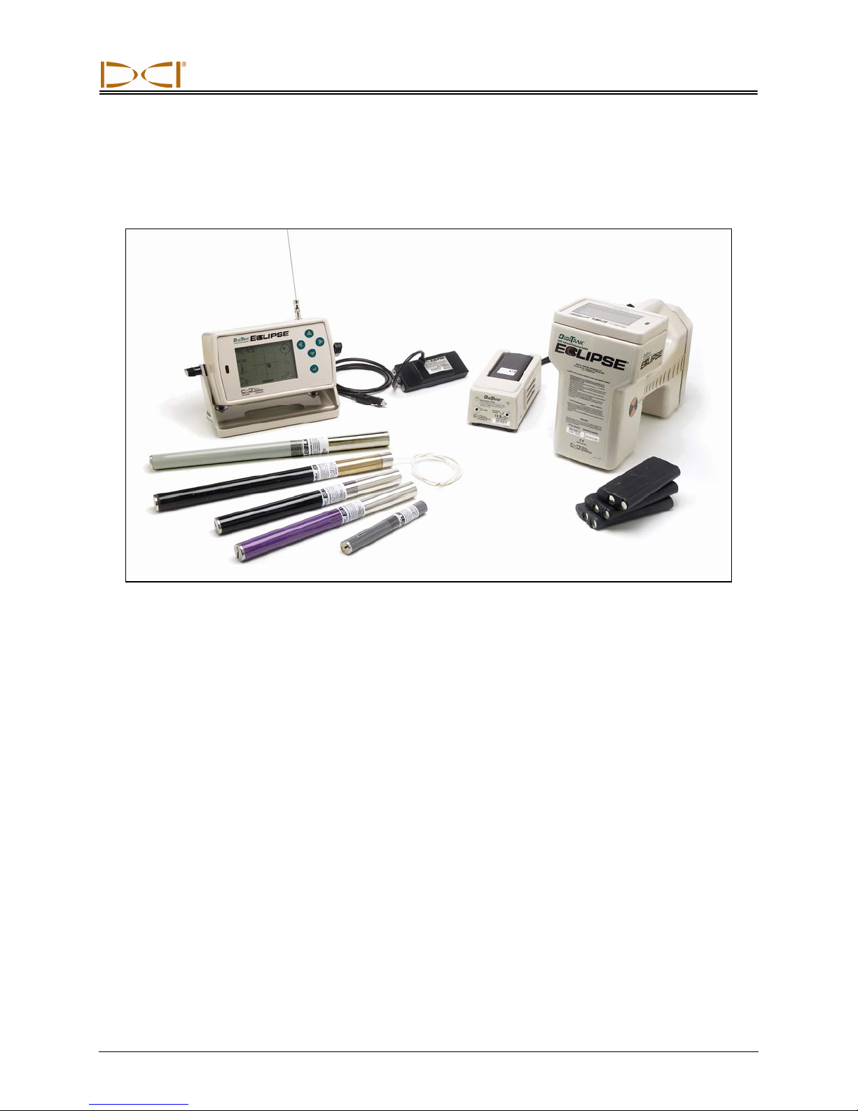
Types of Eclipse Transmitters
DCI manufactures four different battery-operated Eclipse transmitters—a standard transmitter (black
tube), a short-range mini transmitter (gray tube), a long-range transmitter (light-gray tube), and a dualfrequency transmitter (lavender tube). We also offer a cable transmitter (see Cable System section for
information on the cable transmitter). For especially difficult locating jobs, such as when walkover locating
is not possible, DCI offers the SST wireline transmitter, which is part of the Eclipse SST advanced HDD
guidance system. For deep auger-boring applications, we offer a 60-in. (1524-mm) auger-boring cable
transmitter that can be tracked for line and precision grade down to 200 ft (61 m). Call DCI or visit
www.digitrak.com for more information on these products.
The standard Eclipse transmitter emits a 12-kHz signal and provides a depth range of approximately 50 ft
(15.2 m). The standard transmitter is 15.00 in. (381.0 mm) long and 1.25 in. (31.8 mm) in diameter.
Standard Eclipse Transmitter
The short-range mini transmitter emits a 12-kHz signal and provides a depth range of approximately 15 ft
(4.6 m). The mini transmitter is 8.00 in. (203.2 mm) long and 1.00 in. (25.4 mm) in diameter. DCI offers an
adapter for the mini transmitter to fit in a standard-sized housing. The outer dimensions of the adapter
with the mini transmitter inside are exactly the same as those of the standard and dual-frequency
transmitters (15.00 in. x 1.25 in. [381.0 mm x 31.8 mm]). Call DCI for additional information.
Mini Eclipse Transmitter
Mini Eclipse Transmitter with Housing Adapter
DigiTrak® Eclipse® Operator’s Manual 35
Page 36

Transmitter
Long-Range Eclipse Transmitter
The long-range Eclipse transmitter emits a 12-kHz signal and provides a depth range of approximately
85 ft (25.9 m). The long-range transmitter is 19.00 in. (482.6 mm) long and 1.25 in. (31.8 mm) in diameter.
This transmitter requires the use of one 3.6-V DCI SuperCell Lithium Battery. The use of two C-cell
alkaline batteries will result in very short battery life—approximately 2 hours. Therefore, DCI recommends
that you only use the SuperCell Lithium Battery in the long-range transmitter.
Eclipse Dual-Frequency Transmitter
The dual-frequency transmitter is the same size as the standard transmitter, and it can be set to transmit
in dual-frequency mode (sending signal at both 1.5-kHz and 12-kHz frequencies) or in single-frequency
mode (sending signal at 12 kHz). Each frequency mode offers specific advantages:
¾ The dual-frequency mode provides a depth range of approximately 40 ft (12.2 m) at either fre-
quency, and is recommended in areas where rebar, wire mesh, or other metal (passive) interference may be encountered.
¾ The single-frequency mode (12 kHz) provides a depth range of approximately 60 ft (18.3 m) and
is intended for use in areas of active interference.
When using the standard Eclipse transmitter (black tube), the mini transmitter (gray tube), the long-range
transmitter (light-gray tube), or the dual-frequency transmitter set to single-high (SH) or dual-high (DH)
mode, you should see Low Fre on the receiver’s main menu display (meaning you are operating at high
frequency). When using the dual-frequency transmitter set to dual-low (DL) mode, you should see High
Fre on the receiver’s main menu display (meaning you are operating at low frequency).
Pitch and Roll Information
Eclipse transmitters measure pitch in percent slope or degree increments. Pitch measurements are
displayed in 0.1% increments from 0% to ±100% (or 0° to ±45°).
The transmitter roll is displayed in 24 positions, similar to the hour and ½ hour positions on a clock.
36 DigiTrak® Eclipse® Operator’s Manual
Page 37

Transmitter
Batteries
The 15.00-in. (381.0-mm) transmitters require two C-cell alkaline batteries or one DCI SuperCell Lithium
Battery. The 19.00-in. (482.6-mm) long-range transmitter requires one DCI SuperCell Lithium Battery,
although two C-cell alkaline batteries will work for a very short period of time. The mini transmitter
requires one AA alkaline battery. DCI does not recommend using non-alkaline or rechargeable batteries.
The batteries are loaded into the battery compartment with the positive terminals going in first.
The amount of power remaining in the batteries is displayed on the depth and predicted depth display
screens (see Locating section). However, the SuperCell battery will display as fully charged until
moments before it goes dead. Therefore, it is necessary to monitor drilling hours when using the
SuperCell battery.
When using two C-cell alkaline batteries, it may be beneficial to solder or wrap the batteries to avoid
battery chatter in hard ground conditions.
Temperature Updates and Overheat Indicator
Transmitter temperature information is displayed both digitally and graphically on the receiver. When the
transmitter’s temperature increases, audible warning tones are emitted by both the receiver and the
remote display. Temperatures are displayed in degrees Fahrenheit (°F) when the depth measurement
mode is in English units, and degrees Celsius (°C) when the depth mode is in metric units.
Normal drilling temperatures range from 64°F (16°C) to 104°F (40°C). DCI recommends that you keep the
transmitter temperature below 104°F (40°C) by slowing penetration rates and/or adding more drilling fluid.
Each transmitter has a temperature overheat indicator (temp dot) located on the stainless-steel front end
cap. The temp dot on a new transmitter is white (see photo). If the temp dot is black, the transmitter has
been exposed to temperatures in excess of 220°F (104°C). The transmitter should then be deemed
unreliable and should not be used on further projects.
Temp Dot
Front End Cap of Transmitter Showing Temp Dot and Index Slot
DigiTrak® Eclipse® Operator’s Manual 37
Index Slot at
6 o’clock Position
Page 38

Transmitter
Start Up and Frequency Modes
Starting the Standard Eclipse Transmitter
1. Remove battery cap, and load two C-cell alkaline batteries (or a SuperCell lithium battery) into the
battery compartment, positive terminal(s) first.
2. Replace the battery cap and screw it in until it is flush with the end of the battery compartment.
3. To view the transmitter information, select Locate from the main menu screen on the receiver, and
click the trigger.
4. Verify that the signal strength is approximately 528 by placing the receiver 10 ft (3 m) from the transmitter (in the housing). You will see SH above the temperature thermometer to indicate the
transmitter is in single-high mode. (The standard transmitter only has one frequency.)
Starting the Mini Eclipse Transmitter
1. Remove battery cap, and load one AA-cell alkaline battery into the battery compartment, positive
terminal first.
2. Replace the battery cap and screw it in until it is flush with the end of the battery compartment.
3. To view the transmitter information, select Locate from the main menu screen on the receiver, and
click the trigger.
4. Verify that the signal strength is 360 to 370 by placing the receiver 10 ft (3 m) from the transmitter (in
the housing). You will see SH above the temperature thermometer to indicate the transmitter is in
single-high mode. (The mini transmitter only has one frequency).
Starting the Long-Range Eclipse Transmitter
1. Remove battery cap, and load one SuperCell lithium battery into the battery compartment, positive
terminal first.
2. Replace the battery cap and screw it in until it is flush with the end of the battery compartment.
3. To view the transmitter information, select Locate from the main menu screen on the receiver, and
click the trigger.
4. Verify that the signal strength is approximately 620 by placing the receiver 10 ft (3 m) from the
transmitter (in the housing). You will see SH above the temperature thermometer to indicate the
transmitter is in single-high mode. (The long-range transmitter only has one frequency.)
38 DigiTrak® Eclipse® Operator’s Manual
Page 39

Transmitter
Starting the Eclipse Dual-Frequency Transmitter
The Eclipse dual-frequency transmitter can be set to transmit in two different modes—dual-frequency
mode (transmitting at 1.5 kHz and 12 kHz) or single-frequency mode (transmitting at 12 kHz).
The frequency mode can only be changed at startup when the batteries are loaded. You cannot change
the frequency mode of the transmitter while drilling.
The frequency mode is established by the orientation of the transmitter at startup, when the batteries are
loaded into the battery compartment.
Starting the Dual-Frequency Transmitter
in Dual-Frequency Mode
1. Remove the battery cap, and hold the transmitter vertically with the battery
compartment up and the front end pointing down (see diagram).
2. Load two C-cells (or a SuperCell lithium battery) into the battery compartment with the positive terminal entering first.
3. Replace the battery cap while rotating the transmitter in this vertical position
until the cap is flush with the end of the battery compartment.
4. Power up the receiver, and verify that the main menu option shows Low Fre
on the main menu screen.
5. Select Locate from the receiver’s main menu screen, and click the trigger.
6. You will see DH above the thermometer on the left side of the screen to
indicate the transmitter is in dual-high mode.
7. Verify that the signal strength is 530 to 540 by placing the receiver 10 ft
(3 m) from the transmitter (in the housing), and record the value.
8. Return to the main menu screen on the receiver, select Low Fre, and click
the trigger.
9. Select Locate from the main screen, and click the trigger.
10. You will see DL above the thermometer on the left side of the screen to indicate the transmitter is in
dual-low mode.
11. Verify that the signal strength is 480 to 490 when the receiver is 10 ft (3 m) from the transmitter (in the
housing), and record the value.
Loading Batteries
for Dual Mode
DigiTrak® Eclipse® Operator’s Manual 39
Page 40

Transmitter
Starting the Dual-Frequency Transmitter
in Single-Frequency Mode
1. Remove the battery cap, and hold the transmitter vertically with the battery
compartment down and the front end pointing up (see diagram).
2. Load two C-cells (or a SuperCell battery) into the battery compartment with
the positive terminal(s) entering first.
3. Replace the battery cap while rotating the transmitter in this vertical position
until the cap is flush with the end of the battery compartment.
4. Power up the receiver and verify that you see Low Fre on the main menu
screen.
5. Select Locate from the receiver’s main menu screen, and click the trigger.
6. You will see SH above the thermometer on the left side of the screen to
indicate the transmitter is in single-high mode.
7. Verify that the signal strength is approximately 565 when the receiver is 10 ft
(3 m) from the transmitter (in the housing), and record the value.
Loading Batteries
for Single Mode
Sleep Mode (Automatic Shutoff)
The Eclipse transmitter will shut down (go into “sleep” mode) to conserve battery power if it is stationary
for 15 minutes. To “wake up” the transmitter, simply rotate the drill string.
Transmitter Housing Requirements
To achieve maximum range and battery life for all of DCI’s transmitters, the slots in the housing must be
long enough and correctly positioned. Slot measurements should always be taken from the inside of the
housing.
DCI recommends at least three slots equally spaced around the circumference of the housing. The slots
must be at least 1/16 or 0.0625 in. (1.6 mm) wide. The position and length requirements of the housing
slots for the different Eclipse transmitters are given below.
For the standard and dual-frequency transmitters (15.00 in./381.0 mm long), each slot should begin at
least 2.0 in. (51 mm) from the front or index cap end of the transmitter and must be at least 8.5 in. (216
mm) long (see figure below).
Battery Compartment End Index Cap End
Standard and Dual-Frequency Transmitter Housing Slot Requirements
40 DigiTrak® Eclipse® Operator’s Manual
Slot Position
Slot Length
8.5 in. (216 mm)
2.0 in.
(51 mm)
Page 41

Transmitter
For the mini transmitter (8.00 in./203.2 mm long), each slot should begin at least 1.25 in. (32 mm) from
the front or index cap end of the transmitter and must be at least 3.75 in. (95 mm) long (see figure below).
Battery
Compartment End
Slot Position
Slot Length
3.75 in. (95 mm)
Index
Cap End
1.25 in.
(32 mm)
Mini Transmitter Housing Slot Requirements
For the long-range transmitter (19.00 in./482.6 mm long), each slot should begin at least 2.0 in. (51 mm)
from the front or index cap end of the transmitter and must be at least 13.0 in. (330 mm) long (see figure
below).
Battery Compartment End Index Cap End
Slot Position
Slot Length
13.0 in. (330 mm)
2.0 in.
(51 mm)
Long-Range Transmitter Housing Slot Requirements
General Transmitter Care Instructions
¾ Clean the springs in the battery compartment and the threads of the battery cap and O-ring.
Emery cloth can also be used to remove any oxidation buildup.
¾ Verify that the transmitter fits snugly into the housing. It may be necessary to wrap the transmitter
with tape or O-rings.
¾ Send in the Product Registration card for the 90-day limited warranty.
DigiTrak® Eclipse® Operator’s Manual 41
Page 42

Transmitter
Notes
42 DigiTrak® Eclipse® Operator’s Manual
Page 43

DIGITAL CONTROL INCORPORATED
r
Battery Charger
Rechargeable
Battery Pack
AC Adapt e
AC Power
Cord
Unexposed Terminal
DO NOT EXPOSE
Control Panel
DC Power
Cord
Negative
Terminal
Positive
Terminal
Battery Charger
The DCI battery charger unit, which includes AC and DC power cords and an AC adapter, is provided
with the Eclipse system, along with four rechargeable DCI battery packs. The battery packs are used to
power the Eclipse receiver and remote display.
The battery charger can operate from AC (100–240 V) or DC (12–28 V) power sources. The battery
charger has specific cords for AC or DC power sources, as shown in the photo above. The AC power
cord is also specific to your global geographic area of operation.
A fully charged battery pack measures between 16.5 V and 17.1 V and will power an Eclipse receiver for
approximately 4 hours or an Eclipse remote display for approximately 6 hours before recharging is
required. A battery is considered discharged at 14.4 V.
Only two terminals are exposed on a battery pack (as shown in the above photo). If the third terminal
becomes exposed or the insulating material over the battery shows signs of damage, the battery pack
must be replaced through an authorized dealer.
Charging or using damaged or non-DCI battery packs may damage the charger, the receiver, or the
remote display, and will void the warranty.
DigiTrak® Eclipse® Operator’s Manual 43
Page 44

Battery Charger
r
AC/DC Power Setup
To install either the AC adapter or the DC power cord,
insert the charger plug into the power port on the back
of the battery charger (see photo to right) and rotate a
quarter turn in either direction to lock it in place.
If using AC power, connect the AC power cord to the
power adapter, then plug the cord into the AC power
receptacle (wall outlet).
If using DC power, plug the DC power cord directly into
the DC power receptacle.
Your battery charger is now ready to use.
Inserting Charger Plug into Power Port
Charging a Battery
1. With power supplied to the battery charger, place a battery pack into the charger with the terminal
end making contact with the springs in the battery charger. The red light will illuminate, indicating
that the battery is charging. However, the battery may require discharging to remove any residual
charge and prolong the battery life; DCI recommends that you discharge a battery pack, as instructed
in step 2, at least once a month.
Red Light:
Solid indicates unit
–
is charging.
– Blinking indicates
low-voltage battery
or power interruption.
Green Light:
Solid indicates
–
battery is fully
charged.
–
Blinking indicates
battery is being
discharged.
Charge Button
44 DigiTrak® Eclipse® Operator’s Manual
Discharge Button
Serial Numbe
Battery Charger Control Panel
Page 45

®
DIGITAL CONTROL INCORPORATED
NOTE: If a battery becomes drained below 4 V, the charger will not immediately recognize the
battery. Leave the battery in the charger and press the charge button. Within a few
minutes, the red light will begin to blink indicating the charger has recognized the
battery. The red light will illuminate solidly within 30 seconds to 1 minute indicating
that the battery is charging on a full cycle.
2. If the battery needs discharging, press the discharge button on the battery charger; the green light will
begin to blink indicating the battery is being discharged. When the battery is completely discharged,
the green light will stop blinking and the charge cycle will automatically start, as indicated by the solid
red light.
NOTE: The discharge cycle may last for up to 4 hours depending on the amount of residual
charge in the battery. Typically, discharging will last for just a few minutes if the
Eclipse receiver or remote has indicated low battery voltage.
3. When the charging cycle is complete, the green light will automatically illuminate indicating that the
battery is charged and ready for use. The battery may take up to 4 hours to charge. The voltage on a
fully charged battery is between 16.5 V and 17.1 V.
NOTE: If a battery is left in the charger during a power interruption, the red or green light may
flash and the battery will begin to discharge on its own. After the power has resumed,
simply remove and replace the battery pack.
DigiTrak® Eclipse® Operator’s Manual 45
Page 46

Battery Charger
Notes
46 DigiTrak® Eclipse® Operator’s Manual
Page 47

DIGITAL CONTROL INCORPORATED
Locating
The graphic display on the Eclipse receiver uses icons to show readings and system status information.
The locate mode screen provides real-time data about the transmitter’s temperature, frequency mode,
pitch, roll, and signal strength, in addition to displaying the channel setting.
Pitch
Frequency
Mode
Transmitter
Temperature
7.5
SH
%
Clock/Roll
Pitch/Roll
Update
Indicator
75°F
CH:B1
Channel
Setting
Locate Mode Screen
The depth mode screen (trigger held in) provides the same real-time data given on the locate mode
screen and also displays the ultrasonic height setting, the transmitter’s depth, and battery status
information for both the receiver and the transmitter. The “lock in” symbol (the letter “R”) appears when
you hold in the trigger to “lock in” on the reference signal at a locate point.
411
Signal
Strength
Ultrasonic
Setting
Depth of
Transmitter
Receiver
Battery Status
Receiver Battery
Voltage Remaining
DigiTrak® Eclipse® Operator’s Manual 47
7.5
%
SH
75°F
CH:B1
15.8
Depth Display Screen
Signal “Lock in”
Reference Symbol
R
456.5
Transmitter Battery
Status (shown full)
Page 48

Locating
Locate Points (FLP & RLP) and Locate Line (LL)
Three positions or locations within the transmitter’s field are used to locate the transmitter below ground.
Two of these locations represent extensions of the transmitter. One point is in front of the transmitter (the
front locate point or FLP), and the other is behind the transmitter (the rear locate point or RLP).
The third location is a line that represents the position of the transmitter. This
line is perpendicular to the
transmitter and is referred to as the locate line or LL.
The figure on the left below shows the geometry of the FLP, RLP, and LL from top (bird’s-eye) and side
views. Note how the RLP and FLP are equal distances from the LL when the transmitter is level and the
ground surface is level.
The figure on the right shows the geometry of the locate points and locate line when the transmitter is at a
negative or downward pitch. Note how, in this case, the RLP and FLP are at different distances from the
LL.
Bird's-Eye View
(Looking Down)
Drill
Drill
RLP
Axis Line
Side View
Ground
Surface
RLP
LL
Transmitter
LL
FLP
FLP
Bird's-Eye View
(Looking Down)
Drill
Axis Line
Side View
Ground
Surface
Drill
LL
RLP FLP
Transmitter (Negative
or Downward Pitch)
LL
RLP
FLP
Transmitter
Top and Side Views of FLP, RLP, Top and Side Views of FLP, RLP,
and LL When Transmitter Is and LL When Transmitter Is
Level with the Ground at Negative or Downward Pitch
48 DigiTrak® Eclipse® Operator’s Manual
Transmitter (Negative
or Downward Pitch)
Page 49

Locating
Locating Procedure
The Eclipse system can be used to locate the transmitter while facing either toward the drill or away from
the drill. The locating procedure given here assumes you are facing away from the drill with the transmitter out ahead of you.
1. Begin locating by clicking the trigger after you have selected the Locate option from the main menu
screen. The locating display will appear, as shown in the graphic on the left below. The Eclipse
locating display (on the left) shows the position of the locate point (the target) with respect to the
receiver (the box in the center of the display). The graphic on the right shows the actual position of
the receiver, the transmitter, and the locate points. Note that the RLP is ahead of and to the left of the
receiver, as shown in the Eclipse display by the target symbol.
Locate Point
(Target)
7.5
%
FLP
SH
75°F
Receiver
(Box)
2. Position the receiver until you get the target in the box as shown below. You are now standing with
the receiver positioned over the RLP.
CH:B1
Eclipse Locating Display
7.5
%
411
Actual Position of
RLP
Receiver and
Transmitter
FLP
SH
Transmitter
LL
Receiver
LL
75°F
CH:B1
Eclipse Locating Display with Target in Box at RLP
DigiTrak® Eclipse® Operator’s Manual 49
RLP
428
Actual Position of
Receiver and
Transmitter
Page 50

Locating
NOTE: To ensure you are over the RLP, you can rotate the receiver 360°, being careful to
keep the receiver display at the center of the rotation. The target should stay in the
same position in the box on the receiver’s display. If it does not, then the receiver’s
antenna may be malfunctioning—you should contact DCI Customer Service, 800-2883610 or 425-251-0559, for assistance.
3. Hold in the trigger for at least one second to “lock in” on the reference signal (you will see the “R”
symbol appear at the top of the display until you release the trigger).
4. Continue walking away from the drill and toward the transmitter. You will see the target move from the
box to the bottom of the screen, and then it will quickly appear at the top of the screen. You will then
see the LL appear as pictured below.
FLP
7.5
%
SH
LL
75°F
RLP
CH:B1
456.5
Actual Position of
Receiver and
Transmitter
Eclipse Locating Display with Operator Approaching LL
5. Position the receiver until the LL lines up with the two horizontal cross hairs. You are now standing on
the LL. To determine the exact lateral position of the transmitter, you will need to find the FLP.
FLP
7.5
%
SH
75°F
RLP
CH:B1
459
459
LL
Eclipse Locating Display with Operator at LL
50 DigiTrak® Eclipse® Operator’s Manual
Actual Position of
Receiver and
Transmitter
Page 51

Locating
6. Continue to walk out ahead of the transmitter and position the receiver until the target is in the box as
shown below.
FLP
7.5
%
SH
LL
75°F
RLP
CH:B1
433.5
Actual Position of
Receiver and
Transmitter
Eclipse Locating Display with Target in Box at FLP
7. While at the FLP, hold the trigger in to observe the predicted depth (11 ft 8 in. in the figure below),
which is the depth the transmitter will be at when it passes under the FLP, and the horizontal distance
in front of the transmitter (8 ft 7 in.), which is the distance that the transmitter will travel to reach the
predicted depth. You will also see the ultrasonic setting (1 ft 10 in.) below the receiver icon and the
receiver’s battery status, including the amount of voltage remaining, in the bottom left corner.
FLP
7.5
%
SH
75°F
RLP
CH:B1
Receiver
15.8
Battery
Voltage
Remaining
Eclipse Predicted Depth Display
When the battery icon appears half full (remaining voltage will be between 14.2 and 14.8), you should
shut off the receiver and replace the battery with a fully charged battery.
R
433.5
Actual Position of
Receiver and
Transmitter
LL
NOTE: You should replace the receiver battery when the receiver battery icon appears half full
(remaining voltage between 14.2 and 14.8).
DigiTrak® Eclipse® Operator’s Manual 51
Page 52

Locating
8. While standing on the FLP and facing back toward the drill, it is possible to “sight in” or align the FLP
with the RLP. This axis line is at a 90° angle (perpendicular) to the LL. Where this axis line crosses
the LL is where the transmitter will be found, below ground.
9. Position the receiver at the intersection of the LL and the line between the RLP and FLP—you will be
above the transmitter. From this location you can observe the depth of the transmitter by simply
holding in the trigger. You will also see the ultrasonic setting and, in the bottom left corner, the
receiver’s battery status.
FLP
7.5
%
SH
LL
75°F
RLP
CH:B1
15.8
Eclipse Depth Display
If you choose to locate the transmitter by standing out in front of it and facing the drill, you can use the
same technique as described above. However, you will first find the FLP, then the LL, and finally the RLP.
Remember that you must “lock in” on the reference signal at the FLP (instead of the RLP) if you use the
method of locating from the front, facing the drill.
It is not always necessary to find both of the locate points (RLP and FLP). However, for the most accurate
locating, DCI recommends that you find both the FLP and the RLP. The line connecting the FLP to the
RLP will provide you with the heading of the transmitter (tool) as well as its position below ground. The
heading information can be particularly useful when the transmitter (tool) hits something that deflects it to
the left or right, resulting in a change of heading.
DCI does not recommend locating the transmitter using the peak signal method.
NOTE: It is very important to position the receiver accurately. The depth reading can be in-
accurate if the receiver is not positioned directly over the drill head.
R
456.5
Actual Position of
Receiver and
Transmitter
52 DigiTrak® Eclipse® Operator’s Manual
Page 53

DIGITAL CONTROL INCORPORATED
The Target Steering® Function
The Target Steering® function allows the Eclipse receiver to be placed out ahead of the drill head and
used as a steering target. To activate the Target Steering function, you must program the receiver with
the desired target depth number. The drill head can then be guided to a point directly below where the
receiver has been placed.
The Eclipse system assumes level topography for the most accurate Target Steering results. It also
assumes that the value programmed for depth is within practical drilling conventions for the bend radius
of the drill string and that of the product being installed. In general, the intended drill path from the current
transmitter position to the target should be simple and not require large pitch or depth changes. As a rule,
the depth cannot change by more than 4 ft (1.2 m) per 35 ft (10.7 m), and the pitch cannot change by
more than 14% per 35 ft (10.7 m).
This section presents information on determining a feasible target depth, programming the target depth
into the receiver, positioning the receiver, and using the remote display’s Target Steering screen to steer
to the target.
NOTE: DCI does not recommend using the Target Steering function in dual-low (DL) mode.
Determining Feasible Target Depth
For the most conservative Target Steering operation, we assume that the ideal drill path is a circular arc
with a radius that accommodates the bend radius of most drill strings and products being installed. As
shown in the diagram below, the feasible steering area is limited to the shaded region bounded by the two
circular arcs.
Surface of
Ground
Target Depth
Depth Change
4 ft (1.2 m) max.
Transmitter
Depth
Transmitter
Target
Feasible
Steering Area
Horizontal Distance
35 ft (10.7 m) max.
Maximum depth change is approximately 4 ft (1.2 m) over horizontal distance of 35 ft (10.7 m).
DigiTrak® Eclipse® Operator’s Manual 53
Diagram of Feasible Steering Area
Page 54

Target Steering
r
The maximum distance that the Eclipse receiver can be placed out ahead of the drill head for Target
Steering is 35 ft (10.7 m). Over this 35-ft range, the following parameters apply:
¾ The maximum depth change is approximately 4 ft (1.2 m).
¾ The maximum pitch change is approximately 14%.
To determine if your desired target depth is feasible:
1. Use the Eclipse receiver to obtain the current transmitter depth with respect to level ground surface.
2. Subtract the current transmitter depth from your desired target depth to obtain the desired depth
change.
NOTE: If the target depth is above the transmitter, then the target depth number is positive; if it is
deeper than the transmitter, then the target depth number is negative.
3. If the desired depth change is less than 4 ft (1.2 m), then you can program the desired target depth as
the target depth (see next section, “Programming Target Depth”). However, if the depth change is
greater than 4 ft (1.2 m), then the desired target depth is not feasible. You will either have to pull back
to increase the available horizontal distance or you must drill toward a different target.
NOTE: DCI does not recommend using the Target Steering function in dual-low (DL) mode.
Programming Target Depth
1. Toggle to the Configure menu item from the main menu screen on the
receiver, and click the trigger.
2. Toggle to the Target Depth menu item, and click the trigger. You will see
an input area similar to that shown in the figure to the right.
3. Enter the correct target depth number using the toggle. The number must
be in decimal format corresponding to either feet or meters. You do not
need to enter a negative sign when programming the Eclipse receiver with
the target depth number.
NOTE: If you are using FT/IN Units for your depth measurement units, you must enter the target
depth number in feet in decimal format not in feet and inches. You do not need to change
your depth measurement mode.
_
_0.00
Curso
54 DigiTrak® Eclipse® Operator’s Manual
Page 55

Target Steering
4. When you have entered the correct target depth number, click the trigger. When the target depth is
programmed and you are in locate mode, you will see a “T” (for target) next to the channel setting in
the lower left corner.
7.5
%
SH
75°F
CH:
B1T
411
“T” Indicates
Target Depth Is
Programmed
Receiver Screen with Target Depth Programmed
NOTE: If you are not using the target depth mode, you should set the target depth to 0.00.
Positioning Receiver as Target
The Target Steering procedure requires correct placement of the receiver. The receiver must be placed
out in front of the transmitter with its back end (where the battery pack is inserted) facing the drill. The
maximum horizontal distance from the transmitter that the receiver should be placed is approximately
35 ft (10.7 m).
NOTE: It is very important that the horizontal placement of the receiver as well as the value input
for the target depth number are within the allowable bend radius of the drill string or the
product being installed.
DigiTrak® Eclipse® Operator’s Manual 55
Page 56

Target Steering
Steering to the Target
Once the target depth number has been entered on the receiver and the receiver is in position as the
target, select Remote from the main menu screen on the remote display to see the Target Steering
screen, as shown below. The steering indicator in this case shows that the drill head is to the left and too
high for the intended path. The steering indicator should be dead center in the display if you are correctly
heading to your programmed target depth. A steering command of 4 o’clock would bring the drill head
toward the target. Note that, for quick viewing and interpretation, the pointed end of the steering indicator
corresponds to the clock position of the head. The horizontal distance from the drill head to the receiver is
indicated at the bottom left part of the display. At the bottom right, the current depth of the drill head is
indicated.
Steering
Indicator
7.5
%
CH:B1
75°F
Horizontal
Distance
Target Steering Screen on Remote Display
A side view of the position of the Eclipse receiver and of the transmitter is shown below on the left. An
end view of the same setup is shown on the right.
4’6
Transmitter
”
Surface of
Ground
20’4
”
4’6
Actual Position
of Transmitter
Target
5’6
”
”
Back of
Receiver
5’6
Side and End Views Showing Positions of Receiver, Transmitter, and Target
”
Target
Current
Depth
56 DigiTrak® Eclipse® Operator’s Manual
Page 57

DIGITAL CONTROL INCORPORATED
Cable System
Power
Supply
Eclipse Cable System
Remote
Display
Cable
Transmitter
Extraction/
Insertion Tool
The Eclipse cable system is designed specifically for bores that:
¾ Have depths in excess of 50 ft (15.2 m).
¾ Have lengths that require several days to drill.
¾ Do not allow walkover locating.
¾ Are in high-interference areas.
The depth and locating ranges of the Eclipse cable system are both approximately 80 ft (24.4 m). These
ranges are dependent upon environmental conditions and characteristics of the housing. Depth and
lateral location information is tracked using the Eclipse receiver.
Cable System Components
The Eclipse cable system consists of four main components (cable transmitter, power supply, remote
display, and cable extraction/insertion tool) and a power source, which are described below.
Eclipse Cable Transmitter – This transmitter measures 19.00 in. (482.6 mm) in length by 1.25 in. (31.8
mm) in diameter. It requires a special rear-load housing with an end plug that allows the transmitter’s
cable to exit the housing. The end plug requires a compression fitting to seal the transmitter from the
drilling fluid. The housing must also have at least three slots equally spaced around the circumference of
the transmitter that
measure 9.0 in. (229
mm) in length and at
least 1/16 or 0.0625 in.
(1.6 mm) in width (see
figure) for proper signal emission.
Wireline End Index Cap End
Slot Position
Slot Length
9.0 in. (229 mm)
2.5 in.
(64 mm)
DigiTrak® Eclipse® Operator’s Manual 57
Slot Geometry on Cable Transmitters
Page 58

Cable System
Power Supply – This unit is inserted into the battery compartment at the back of the remote display. It is
hard wired to the Eclipse cable transmitter with a 10-gauge (white) wire and to the power source with a
gray cable that contains 14-gauge black and red wires.
Battery
Compartment
White Wire
Gray Cable
Power Supply
Insertion of Power Supply in Remote Display
Remote Display with Cable Function – This specially configured remote display supplies power from
the power source to the cable transmitter and displays the cable transmitter’s information. All Eclipse
remote display units manufactured after
February 2002 are equipped with this cable
function and will show the Cable option in the
main menu when the unit is turned on (see
Remote Display section). Remote displays
manufactured prior to February 2002 can be
upgraded to the cable function. To upgrade your
Eclipse remote display, contact DCI.
Cable Extraction/Insertion Tool – This tool is
used for inserting and extracting the Eclipse
cable transmitter to or from the housing. Two
threaded holes (1/4”-20 thread) are provided at
the back of the cable transmitter for threading
the extraction tool (see photo).
NOTE: Never remove the cable transmitter
from the housing by pulling on the wire.
58 DigiTrak® Eclipse® Operator’s Manual
Extraction/
Insertion
Tool
10-gauge
Cable Wire
Cable Transmitter with Cable Extraction/
Insertion Tool Screwed into End
Page 59

Cable System
Power Source – Lead-acid automotive batteries that supply between 12 and 28 V DC are used for the
power source. For bores shorter than 1000 ft (305 m), one 12-V battery will suffice. If the bore length
increases beyond 1000 ft (305 m) or advance rates decrease, additional batteries may be added in series
(see diagram).
–
4
–
12-Volt
Battery
Connect batteries in the order shown by the numbers in circles: 1 , 2 , 3 , 4
Disconnect batteries in the opposite order: 4 , 3 , 2 , 1
+
12–28 Volts DC
2 1
–
+
3
+
12-Volt
Battery
Adding Batteries in Series
Non-DCI Supplies Required for
Operating the Cable System
Items such as compression fittings, 10-gauge copper wire, heat shrink, butt splices, and collector ring
assemblies are not available from DCI. Drill manufacturers or tooling manufacturers will have information
on collector ring (slip-ring) assemblies, mud swivels, and compression fittings. Electrical supply houses
will carry the rest of the equipment needed to connect the wires as drill rods are added to the drill stri ng.
A new option available from DCI is a product called the CableLink
the need for butt splices and heat shrinks. The CableLink system is permanently installed into the drill
pipe, and the wire connection occurs automatically when the pipe ends are threaded together. For more
information, contact DCI.
NOTE: A multimeter should be available for power testing/trouble shooting. For detailed
instructions on troubleshooting the Eclipse cable system, please contact DCI.
DigiTrak® Eclipse® Operator’s Manual 59
®
connection system, which eliminates
Page 60

Cable System
Connecting Power Supply
to Power Source and Cable Transmitter
The gray wire that extends from the power supply has two wires within it—a red wire and a black wire.
The black wire is the ground; it connects to the negative battery terminal, and the red wire connects to the
positive battery terminal. The white wire connects to the cable transmitter wire (see diagram). The Eclipse
remote display and power supply must be connected directly to the power source, not through a wiring
harness or the drill’s auxiliary panel.
Drill Rods
White
Housing
Drill Rig
Black
+
Red
Power Supply
(in Compartment
on Back of Remote
Display)
–
12-Volt
Battery
Ground
Remote Display
Cable
Compression
Fitting
Cable
End Plug
Cable Transmitter
Housing to Transmitter
Base is Negative
Contact for Grounding
Connecting Cable System Components
Grounding the Cable Transmitter
The cable transmitter must be grounded or it will not work—no signal or data will be sent to the remote
display. The ground point on the cable transmitter is the metal end cap (where the wire extends). When
the cable transmitter is properly fitted into the housing, the ground connection will occur automatically,
because it is grounded through the drill. When testing the cable transmitter outside of the housing, you
can make a ground connection by taking a piece of wire and touching the negative terminal of the battery
with one end and touching the other end of the wire to the metal end cap of the cable transmitter.
60 DigiTrak® Eclipse® Operator’s Manual
Page 61

Cable System
Cable Transmitter On/Off
Before you can power up the remote display, you must ensure that the power supply, power source, and
cable transmitter are properly connected, as discussed in the previous sections. After properly connecting
the cable system, push the execute button to power up the remote display. Then select the Cable menu
option. This will enable the remote display to send power to the cable transmitter.
To turn the power off, press the toggle arrows on the remote display to select the Power Off option and
press the execute button. DCI recommends that you turn off the power to the cable transmitter prior to
working with the wire, such as when adding a new drill rod.
At the end of the drilling day it is necessary to stop power to the cable transmitter to conserve the battery
life of the power source. Use the Power Off menu option to turn off the power, then disconnect the power
source from the remote display.
Calibrating the Cable Transmitter
The cable transmitter is calibrated using the 1-point calibration procedure at a distance of 10 ft (3 m)—for
the proper procedure, refer to the 1-Point Calibration discussion under the “Configure Menu” in the
Receiver section. DCI recommends that you always check the depth readings at various locations against
a tape measure to confirm good calibration.
Enabling the Roll Offset Function on the Remote Display
The roll offset function is used when the drill bit (tool) and housing are two separate pieces and their roll
positions do not match when the tool is torqued-up to the housing. The roll offset function is an electronic
compensation to match the transmitter’s 12 o’clock position to the tool’s 12 o’clock position.
Enabling Roll Offset Function
To enable the roll offset function on the remote display:
1. Power up the remote display.
2. Select Configure from the remote display’s main menu and press the execute button.
3. Press the right arrow several times to select Set Roll, and press the execute button; this menu option
will change to Unset Roll.
The remote is now ready for you to set the roll offset number, which you should do if the transmitter’s 12
o’clock position does not match the tool’s 12 o’clock position.
Setting Roll Offset Number
To set the roll offset number:
1. Torque-up the tool to the housing.
2. Orient the tool to 12 o’clock.
3. Place the cable transmitter into the housing and p ower up usin g the Eclipse power supply.
DigiTrak® Eclipse® Operator’s Manual 61
Page 62

Cable System
4. From the main menu on the remote display, select Cable and press the execute button.
5. Press the right arrow, and press it again to select Y for yes, then press the execute button.
Note the “RO” or roll offset number that appears at the top of the remote display to indicate that a
compensation for the transmitter’s roll position has occurred. This number will remain in memory until you
change it; therefore, you can calibrate, change the telemetry channel, and replace the battery without
affecting this roll offset number.
If you will be tracking the cable transmitter with the receiver, you will also need to set the roll offset on the
receiver to ensure that both units display the same roll information. If you have not already enabled the
roll offset function on the receiver using the Set Roll menu option, refer to “Set Roll / Unset Roll (Enabling
and Disabling the Roll Offset Function)” in the Receiver section.
To set the roll offset number on the receiver, after enabling the roll offset function:
1. Torque-up the tool to the housing.
2. Orient the tool to 12 o’clock.
3. Place the cable transmitter into the housing and p ower up usin g the Eclipse power supply.
4. From the remote display’s main menu, select Cable and press the execute b utton.
5. From the receiver’s main menu screen, select Locate and click the trigger.
6. Toggle up one time, select Y for yes, and click the trigger. The transmitter’s roll position should now
match the tool’s position, which is 12 o’clock.
The receiver will display the roll offset number at the top of the screen and the remote display will show
the roll offset number at the top as “RO”.
Locating Using the Cable System
Locating using the cable transmitter system is identical to locating using the battery-operated Eclipse
transmitter—see the Locating section.
The receiver and remote display must be set to the same channel (see the “Configure Menu” section in
the Receiver and Remote Display sections for instructions on changing the telemetry channel and Tele
Option or TLT settings). The receiver and remote will display the pitch, roll, and depth of the cable
transmitter.
Viewing Transmitter Depth or Predicted Depth
The depth or predicted depth of the transmitter can also be viewed on the remote display. The receiver
must be positioned over either the locate line (LL) or one of the locate points (FLP or RLP) for this
function to work—see “Locate Points (FLP & RLP) and Locate Line (LL)” in the Locating section. Also,
this function is only available on Eclipse systems produced after February 2002.
Once the receiver is positioned over the LL, FLP, or RLP, the receiver operator holds in the trigger to take
the depth or predicted depth reading. The remote display will emit a single tone to notify the operator that
the depth information is being displayed. This depth/predicted depth information will remain on the remote
display’s screen for 10 seconds or as long as the receiver’s trigger is held in.
62 DigiTrak® Eclipse® Operator’s Manual
Page 63

Cable System
Viewing Status of Cable System Power Source
The battery status of the power source will display at the bottom of the remote display screen where the
transmitter battery status normally displays. When the battery status symbol appears 100% full, the
battery is delivering at least 16 V of power. When the symbol is 50% full, the battery power is 14.5 V.
When the symbol appears to be 25% full, the battery power is 14.0 V.
NOTE: If the power source is delivering less than 9.7 V, the system will automatically shut off.
Target Steering Function Using the Cable System
The Target Steering function can be used with the Eclipse cable system. In fact, the feasible steering
distance with the cable transmitter is greater than it is with the battery-operated transmitters. With the
cable transmitter, the maximum horizontal distance over which you can program the transmitter is 50 ft
(15.2 m), as opposed to 35 ft (10.7 m) with battery-operated transmitters. Please refer to the previous
section, entitled The Target Steering Function, for instructions on programming target depth.
The feasible steering area when using the cable system is shown below.
Surface of
Ground
Target Depth
Depth Change
5.7 ft (1.74 m) max.
Transmitter
Depth
Transmitter
Target
Feasible
Steering Area
Horizontal Distance
50 ft (15.2 m) max.
Diagram of Feasible Steering Area for Cable System
Maximum depth change is approximately 5.7 ft (1.74 m) over horizontal distance of 50 ft (15.2 m).
DigiTrak® Eclipse® Operator’s Manual 63
Page 64

Cable System
Notes
64 DigiTrak® Eclipse® Operator’s Manual
Page 65

DIGITAL CONTROL INCORPORATED
Troubleshooting
If you have a problem with your Eclipse locating system, review this section to see if you can find the probabl e
cause and a remedy for the problem. If you cannot resolve your problem, then call DCI’s Customer Service
Department (425-251-0559 or 800-288-3610) and we’ll help you find a solution.
Problem Cause / Remedy
Eclipse Receiver
LL will not display Position the receiver over one of the two locate points and hold in the trigger for
at least one second, then release the trigger. The reference “R” should display at
the top of the locate screen and the LL should come up.
Depth information seems
inaccurate
Depth is greater than expected The receiver is set to the wrong frequency setting. Exit to main menu and
Display shows “Recal Tilt”
message dialog box
Targ e t m o v e s err a t ical l y on d ispl a y Contact DCI Customer Service.
Target does not remain in box on
display when receiver is rotated
It is difficult to get LL to line up
with horizontal cross hairs
Display goes blank The screen contrast may have accidentally been adjusted. If so, push the
Display goes dark The screen contrast may need to be adjusted. To adjust the contrast, hold in
Display locks up or becomes
erratic
Transmitter battery status icon
does not display battery status
Pitch, roll, temperature, and/or
transmitter battery status blinks
The elevation of the receiver above the tool has changed while the trigger was
being held in.
Release the trigger, position the receiver wherever you would like to take a
depth reading and then hold in the trigger while keeping the receiver at a
constant elevation.
change the frequency setting. Return to locate screen and take another depth
reading. (For more information, see “Changing the Frequency Setting” in the
Receiver section.)
The receiver battery may be low. Select “N” for No in the dialog box and replace battery. If you selected “Y” for Yes, call DCI Customer Service.
The receiver’s antenna may be malfunctioning. Contact DCI Customer Service
for assistance.
This situation usually occurs when the receiver is placed above rebar. Try
lifting the receiver up as high as possible.
If holding the receiver higher doesn’t help, try taking a step either forward or
backward. Then align the LL to the top or bottom of the Eclipse icon rather
than the cross hair through the center of the icon.
toggle to the right or left several times (at least 8–10) while clicking the trigger.
Try changing the transmitter’s battery.
the trigger and repetitively push the toggle to the right or left.
The contrast can also be adjusted by holding the toggle in either the left
position or the right position while clicking the trigger.
The battery is probably dead. Replace the battery with a fully charged battery,
and click the trigger to power up the unit.
Turn receiver off and then back on. Go back into the locate mode and hold the
trigger to view the transmitter battery icon with status bars inside.
Change the transmitter’s battery.
Move receiver closer to transmitter.
Move receiver away from potential interference sources.
DigiTrak® Eclipse® Operator’s Manual 65
Page 66

Troubleshooting
Problem Cause / Remedy
Eclipse Receiver (cont.)
Pitch, roll, or depth information is
different than on remote display
Eclipse Remote Display
Display goes blank The screen contrast may have accidentally been ad justed. If so, push the right
Display goes dark The screen contrast may need to be adjusted. To adjust the contrast, push in
Display locks up The battery is probably dead. Replace the battery with a fully charged battery,
Display will not turn on The battery is not properly installed. Insert battery so that the two exposed
Display will not show depth Software version in remote is earli er than February 2002. Call DCI to upgrade
Update indicator stops rotating Receiver is not in locate mode and, therefore, is not sending data to the
Pitch, roll, or depth information is
different than on the receiver
Pitch, roll, temperature, and/or
transmitter battery status blinks
Steer-to target disappears Place the receiver above the FLP, RLP, or LL and hold in the trigger. This will
Loss of data Verify that the receiver and remote display are set to the same channel and
Receiver and remote display may be set to different channels or may be using
different measurement settings. Verify that both units are set to the same
channel, are set to the same grade mode, and are set to the same depth
measurement mode.
If you confirm that all settings are the same on both devices and there is still a
problem, then try using a different channel.
or left toggle arrow several times (at least 8–10) while pushing in the execute
button, or push in the right or left toggle arrow while repetitively pushing the
execute button.
Try changing the transmitter’s battery.
the execute button while repetitively pushing the right or left toggle arrow, or
push the left or right toggle arrow in while repetitively pushing the execute
button.
and press the execute button to power up the unit.
terminals make contact with the bottom two springs in the remote display’s
battery compartment.
The battery voltage is too low. Replace battery.
your software.
remote display. NOTE: The receiver must be in locate mode to send signals to
the remote display.
Remote is not receiving information from the receiver. Try repositioning the
receiver and/or the remote so that there is less interference between them.
Receiver and remote display may be set to different channels or may be using
different measurement settings. Verify that both units are set to the same
channel, are set to the same grade mode, and are set to the same depth
measurement mode.
If you confirm that all settings are the same on both devices and there is still a
problem, then try using a different channel.
Move receiver closer to transmitter.
Move receiver and/or remote display away from potential interference sources.
reset the remote display screen to Target Steering mode.
that the Tele Option or TLT settings are correct.
From the receiver, exit locate mode and then go back into locate mode.
66 DigiTrak® Eclipse® Operator’s Manual
Page 67

DIGITAL CONTROL INCORPORATED
Appendix
The information and tables contained in this appendix provide further assistance for confirming the position of the Transmitter. The following information is provided:
Depth Increase in Inches (Centimeters) per 6-foot (1.8 meter) Rod
Depth Increase in Inches (Centimeters) per 10-foot (3-m eter) Rod
Depth Increase in Inches (Centimeters) per 15-foot (4.6-m eter) Rod
Percent of Grade to Degree Conversions (0.1% Pitch Transmitters or Sensitive Pitch)
Degree to Percent of Grade Conversions (0.1% Pitch Transmitters)
Calculating Depth Based on Distance Between FLP and RLP
DigiTrak® Eclipse® Operator’s Manual 67
Page 68

Appendix
Depth Increase in Inches (Centimeters)
per 6-foot (1.8 meter) Rod
Percent Depth Increase Percent Depth Increase
1
2
3
4
5
6
7
8
9
10
11
12
13
14
15
16
17
18
19
20
21
22
23
24
25
26
27
0.6 (1.5)
1.2 (3.0)
1.8 (4.6)
2.4 (6.1)
3.0 (7.6)
3.6 (9.1)
4.2 (10.7)
4.8 (12.2)
5.4 (13.7)
6.0 (15.2)
6.6 (16.8)
7.2 (18.3)
7.8 (19.8)
8.4 (21.3)
9.0 (22.9)
9.6 (24.4)
10.2 (25.9)
10.8 (27.4)
11.4 (29.0)
12.0 (30.5)
12.6 (32.0)
13.2 (33.5)
13.8 (35.1)
14.4 (36.6)
15.0 (38.1)
15.6 (39.6)
16.2 (41.1)
28
29
30
31
32
33
34
35
36
37
38
39
40
41
42
43
44
45
46
47
50
55
60
70
80
90
100
16.8 (42.7)
17.4 (44.2)
18.0 (45.7)
18.6 (47.2)
19.2 (48.8)
19.8 (50.3)
20.4 (51.8)
21.0 (53.3)
21.6 (54.9)
22.2 (56.4)
22.8 (57.9)
23.4 (59.4)
24.0 (61.0)
24.6 (62.5)
25.2 (64.0)
25.8 (65.5)
26.4 (67.1)
27.0 (68.6)
27.6 (70.1)
28.2 (71.6)
30.0 (76.2)
33.0 (83.8)
36.0 (91.4)
42.0 (106.7)
48.0 (121.9)
54.0 (137.2)
60.0 (152.4)
68 DigiTrak® Eclipse® Operator’s Manual
Page 69

Appendix
Depth Increase in Inches (Centimeters)
per 10-foot (3-meter) Rod
Percent Depth Increase Percent Depth Increase
1
2
3
4
5
6
7
8
9
10
11
12
13
14
15
16
17
18
19
20
21
22
23
24
25
26
27
1 (2)
2 (5)
4 (10)
5 (13)
6 (15)
7 (18)
8 (20)
10 (25)
11 (28)
12 (30)
13 (33)
14 (36)
15 (38)
17 (43)
18 (46)
19 (48)
20 (51)
21 (53)
22 (56)
24 (61)
25 (64)
26 (66)
27 (69)
28 (71)
29 (74)
30 (76)
31 (79)
28
29
30
31
32
33
34
35
36
37
38
39
40
41
42
43
44
45
46
47
50
55
60
70
80
90
100
32 (81)
33 (84)
34 (86)
36 (91)
37 (94)
38 (97)
39 (99)
40 (102)
41 (104)
42 (107)
43 (109)
44 (112)
45 (114)
46 (117)
46 (117)
47 (119)
48 (122)
49 (124)
50 (127)
51 (130)
54 (137)
58 (147)
62 (157)
69 (175)
75 (191)
80 (203)
85 (216)
DigiTrak® Eclipse® Operator’s Manual 69
Page 70

Appendix
Depth Increase in Inches (Centimeters)
per 15-foot (4.6-meter) Rod
Percent Depth Increase Percent Depth Increase
1
2
3
4
5
6
7
8
9
10
11
12
13
14
15
16
17
18
19
20
21
22
23
24
25
26
27
2 (5)
4 (10)
5 (13)
7 (18)
9 (23)
11 (28)
13 (33)
14 (36)
16 (41)
18 (46)
20 (51)
21 (53)
23 (58)
25 (64)
27 (69)
28 (71)
30 (76)
32 (81)
34 (86)
35 (89)
37 (94)
39 (99)
40 (102)
42 (107)
44 (112)
45 (114)
47 (119)
28
29
30
31
32
33
34
35
36
37
38
39
40
41
42
43
44
45
46
47
50
55
60
70
80
90
100
49 (124)
50 (127)
52 (132)
53 (135)
55 (140)
56 (142)
58 (147)
59 (150)
61 (155)
62 (157)
64 (163)
65 (165)
67 (170)
68 (173)
70 (178)
71 (180)
72 (183)
74 (188)
75 (191)
77 (196)
80 (203)
87 (221)
93 (236)
103 (262)
112 (284)
120 (305)
127 (323)
70 DigiTrak® Eclipse® Operator’s Manual
Page 71

Appendix
Percent of Grade to Degree Conversions
(0.1% Pitch Transmitters or Sensitive Pitch)
Percent Degree Percent Degree Percent Degree Percent Degree
0.1
0.2
0.3
0.4
0.5
0.6
0.7
0.8
0.9
1
1.1
1.2
1.3
1.4
1.5
1.6
1.7
1.8
1.9
2
2.1
2.2
2.3
2.4
2.5
0.1
0.1
0.2
0.2
0.3
0.3
0.4
0.5
0.5
0.6
0.6
0.7
0.7
0.8
0.9
0.9
1.0
1.0
1.1
1.1
1.2
1.3
1.3
1.4
1.4
2.6
2.7
2.8
2.9
3
3.1
3.2
3.3
3.4
3.5
3.6
3.7
3.8
3.9
4
4.1
4.2
4.3
4.4
4.5
4.6
4.7
4.8
4.9
5
1.5
1.5
1.6
1.7
1.7
1.8
1.8
1.9
1.9
2.0
2.1
2.1
2.2
2.2
2.3
2.3
2.4
2.5
2.5
2.6
2.6
2.7
2.7
2.8
2.9
5.1
5.2
5.3
5.4
5.5
5.6
5.7
5.8
5.9
6
6.1
6.2
6.3
6.4
6.5
6.6
6.7
6.8
6.9
7
7.1
7.2
7.3
7.4
7.5
2.9
3.0
3.0
3.1
3.1
3.2
3.3
3.3
3.4
3.4
3.5
3.5
3.6
3.7
3.7
3.8
3.8
3.9
3.9
4.0
4.1
4.1
4.2
4.2
4.3
7.6
7.7
7.8
7.9
8
8.1
8.2
8.3
8.4
8.5
8.6
8.7
8.8
8.9
9
9.1
9.2
9.3
9.4
9.5
9.6
9.7
9.8
9.9
10
4.3
4.4
4.5
4.5
4.6
4.6
4.7
4.7
4.8
4.9
4.9
5.0
5.0
5.1
5.1
5.2
5.3
5.3
5.4
5.4
5.5
5.5
5.6
5.7
5.7
DigiTrak® Eclipse® Operator’s Manual 71
Page 72

Appendix
Degree to Percent of Grade Conversions
(0.1% Pitch Transmitters)
Degrees Percent
0.1
0.2
0.3
0.4
0.5
0.6
0.7
0.8
0.9
1
1.1
1.2
1.3
1.4
1.5
1.6
1.7
1.8
1.9
2
2.1
2.2
2.3
2.4
2.5
2.6
2.7
2.8
2.9
3
0.2
0.3
0.5
0.7
0.9
1.0
1.2
1.4
1.6
1.7
1.9
2.1
2.3
2.4
2.6
2.8
3.0
3.1
3.3
3.5
3.7
3.8
4.0
4.2
4.4
4.5
4.7
4.9
5.1
5.2
Degrees Percent
3.1
3.2
3.3
3.4
3.5
3.6
3.7
3.8
3.9
4
4.1
4.2
4.3
4.4
4.5
4.6
4.7
4.8
4.9
5
5.1
5.2
5.3
5.4
5.5
5.6
5.7
5.4
5.6
5.8
5.9
6.1
6.3
6.5
6.6
6.8
7.0
7.2
7.3
7.5
7.7
7.9
8.0
8.2
8.4
8.6
8.7
8.9
9.1
9.3
9.5
9.6
9.8
10.0
72 DigiTrak® Eclipse® Operator’s Manual
Page 73

Appendix
Calculating Depth Based on
Distance Between FLP and RLP
It is possible to estimate the transmitter’s depth should the information displayed in the depth/distance
window become unreliable. This is only possible if the pitch and negative locate points are reliable and
the ground surface is level.
To estimate the transmitter’s depth, first measure the distance between the FLP and the RLP. The pitch
of the transmitter must also be reliably known. Using the Depth Estimation Table below, find the divider
that most closely corresponds to the transmitter’s pitch. Then use the following formula to estimate the
depth:
Depth =
For example, if the transmitter’s pitch is 34% then the corresponding divider value (from the table) is 1.50.
In this example, the distance between the FLP and the RLP is 11.5 ft (3.5 m). The depth would be:
Depth ==
1.50
ft 11.5
7.66
Divider
ft or approximately 7.7 ft (2.35 m)
RLPandFLPbetweenDistance
Depth Estimation Table
Pitch Divider Pitch Divider Pitch Divider Pitch Divider
0 1.41 26 1.47 52 1.62 78 1.84
2 1.41 28 1.48 54 1.63 80 1.85
4 1.42 30 1.48 56 1.64 82 1.87
6 1.42 32 1.49 58 1.66 84 1.89
8 1.42 34 1.50 60 1.68 86 1.91
10 1.42 36 1.51 62 1.69 88 1.93
12 1.43 38 1.52 64 1.71 90 1.96
14 1.43 40 1.54 66 1.73 92 1.98
16 1.43 42 1.55 68 1.74 94 2.00
18 1.44 44 1.56 70 1.76 96 2.02
20 1.45 46 1.57 72 1.78 98 2.04
22 1.45 48 1.59 74 1.80 100 2.06
24 1.46 50 1.60 76 1.82
DigiTrak® Eclipse® Operator’s Manual 73
Page 74

Appendix
Notes
3-1100-00-K
74 DigiTrak® Eclipse® Operator’s Manual
Page 75

DIGITAL
CONTROL
19625 62nd Ave. S., Suite B-103 y Kent, WA 98032 USA y (425) 251-0559 OR (800) 288-3610 y FAX (253) 395-2800
www.digitrak.com (Web Site) DCI@digital-control.com (E-mail)
INCORPORATED
LIMITED WARRANTY
Digital Control Incorporated ("DCI") warrants that when shipped from DCI each DCI product (“DCI Product”) will
conform to DCI’s current published specifications in existence at the time of shipment and will be free, for the
warranty period (“Warranty Period”) described below, from defects in materials and workmanship. The limited
warranty described herein (“Limited Warranty”) is not transferable, shall extend only to the first end-user (“User”)
purchasing the DCI Product from either DCI or a dealer expressly authorized by DCI to sell DCI Products
(“Authorized DCI Dealer”), and is subject to the following terms, conditions and limitations:
1. A Warranty Period of twelve (12) months shall apply to the following new DCI Products: receivers/locators,
remote displays, battery chargers and rechargeable batteries, and DataLog
Period of ninety (90) days shall apply to all other new DCI Products, including transmitters, accessories, and
software programs and modules. Unless otherwise stated by DCI, a Warranty Period of ninety (90) days shall
apply to: (a) a used DCI Product sold either by DCI or by an Authorized DCI Dealer who has been expressly
authorized by DCI to sell such used DCI Product; and (b) services provided by DCI, including testing, servicing,
and repairing an out-of-warranty DCI Product. The Warranty Period shall begin from the later of: (i) the date of
shipment of the DCI Product from DCI, or (ii) the date of shipment (or other delivery) of the DCI Product from an
Authorized DCI Dealer to User.
2. DCI's sole obligation under this Limited Warranty shall be limited to either repairing, replacing, or adjusting, at
DCI's option, a covered DCI Product that has been determined by DCI, after reasonable inspection, to be
defective during the foregoing Warranty Period. All warranty inspections, repairs and adjustments must be
performed either by DCI or by a warranty claim service authorized in writing by DCI. All warranty claims must
include proof of purchase, including proof of purchase date, identifying the DCI Product by serial number.
3. The Limited Warranty shall only be effective if: (i) within fourteen (14) days of receipt of the DCI
Product, User mails a fully-completed Product Registration Card to DCI; (ii) User makes a reasonable
inspection upon first receipt of the DCI Product and immediately notifies DCI of any apparent defect; and
(iii) User complies with all of the Warranty Claim Procedures described below.
®
modules and interfaces. A Warranty
WHAT IS NOT COVERED
This Limited Warranty excludes all damage, including damage to any DCI Product, due to: failure to follow DCI’s
user’s manual and other DCI instructions; abuse; misuse; neglect; accident; fire; flood; Acts of God; improper
applications; connection to incorrect line voltages and improper power sources; use of incorrect fuses;
overheating; contact with high voltages or injurious substances; or other events beyond the control of DCI. This
Limited Warranty does not apply to any equipment not manufactured or supplied by DCI nor, if applicable, to any
damage or loss resulting from use of any DCI Product outside the designated country of use. By accepting a DCI
Product and not returning it for a refund within thirty (30) days of purchase, User agrees to the terms of this
Limited Warranty, including without limitation the Limitation of Remedies and Liability described below, and
agrees to carefully evaluate the suitability of the DCI Product for User's intended use and to thoroughly read and
strictly follow all instructions supplied by DCI (including any updated DCI Product information which may be
obtained at the above DCI website). In no event shall this Limited Warranty cover any damage arising during
shipment of the DCI Product to or from DCI.
User agrees that the following will render the above Limited Warranty void: (i) alteration, removal or tampering
with any serial number, identification, instructional, or sealing labels on the DCI Product, or (ii) any unauthorized
disassembly, repair or modification of the DCI Product. In no event shall DCI be responsible for the cost of or any
damage resulting from any changes, modifications, or repairs to the DCI Product not expressly authorized in
writing by DCI, and DCI shall not be responsible for the loss of or damage to the DCI Product or any other
equipment while in the possession of any service agency not authorized by DCI.
3-1100-00-K Page 1 of 2
Page 76

DCI reserves the right to make changes in design and improvements upon DCI Products from time to time, and
User understands that DCI shall have no obligation to upgrade any previously manufactured DCI Product to
include any such changes.
The foregoing Limited Warranty is DCI’s sole warranty and is made in place of all other warranties, express or
implied, including but not limited to the implied warranties of merchantability and fitness for a particular purpose
and any implied warranty arising from course of performance, course of dealing, or usage of trade. If DCI has
substantially complied with the warranty claim procedures described below, such procedures shall constitute
User’s sole and exclusive remedy for breach of the Limited Warranty.
LIMITATION OF REMEDIES AND LIABILITY
In no event shall DCI nor anyone else involved in the creation, production, or delivery of the DCI Product
be liable for any damages arising out of the use or inability to use the DCI Product, including but not
limited to indirect, special, incidental, or consequential damages or for any cover, loss of information,
profit, revenue or use based upon any claim by User for breach of warranty, breach of contract,
negligence, strict liability, or any other legal theory, even if DCI has been advised of the possibility of
such damages. In no event shall DCI’s liability exceed the amount User has paid for the DCI Product. To
the extent that any applicable law does not allow the exclusion or limitation of incidental, consequential
or similar damages, the foregoing limitations regarding such damages shall not apply
This Limited Warranty gives you specific legal rights, and you may also have other rights which vary from state to
state. This Limited Warranty shall be governed by the laws of the State of Washington.
.
WARRANTY CLAIM PROCEDURES
1. If you are having problems with your DCI Product, you must first contact the Authorized DCI Dealer where it
was purchased. If you are unable to resolve the problem through your Authorized DCI Dealer, contact DCI’s
Customer Service Department in Kent, Washington, USA at the above telephone number between 6:00 a.m. and
6:00 p.m. Pacific Time and ask to speak with a customer service representative. (The above “800” number is
available for use only in the USA and Canada.) Prior to returning any DCI Product to DCI for service, you
obtain a Return Merchandise Authorization (RMA) number. Failure to obtain a RMA may result in delays or return
to you of the DCI Product without repair.
2. After contacting a DCI customer service representative by telephone, the representative will attempt to assist
you in troubleshooting while you are using the DCI Product during actual field operations. Please have all related
equipment available together with a list of all DCI Product serial numbers. It is important that field troubleshooting
be conducted because many problems do not result from a defective DCI Product, but instead are due to either
operational errors or adverse conditions occurring in the User’s drilling environment.
3. If a DCI Product problem is confirmed as a result of field troubleshooting discussions with a DCI customer
service representative, the representative will issue a RMA number authorizing the return of the DCI Product and
will provide shipping directions. You will be responsible for all shipping costs, including any insurance. If, after
receiving the DCI Product and performing diagnostic testing, DCI determines the problem is covered by the
Limited Warranty, required repairs and/or adjustments will be made, and a properly functioning DCI Product will
be promptly shipped to you. If the problem is not covered by the Limited Warranty, you will be informed of the
reason and be provided an estimate of repair costs. If you authorize DCI to service or repair the DCI Product, the
work will be promptly performed and the DCI Product will be shipped to you. You will be billed for any costs for
testing, repairs and adjustments not covered by the Limited Warranty and for shipping costs. In most cases,
repairs are accomplished within 1 to 2 weeks.
must
4. DCI has a limited supply of loaner equipment available. If loaner equipment is required by you and is available,
DCI will attempt to ship loaner equipment to you by overnight delivery for your use while your equipment is being
serviced by DCI. DCI will make reasonable efforts to minimize your downtime on warranty claims, limited by
circumstances not within DCI’s control. If DCI provides you loaner equipment, your equipment must be received
by DCI no later than the second business day after your receipt of loaner equipment. You must return the loaner
equipment by overnight delivery for receipt by DCI no later than the second business day after your receipt of the
repaired DCI Product. Any failure to meet these deadlines will result in a rental charge for use of the loaner
equipment for each extra day the return of the loaner equipment to DCI is delayed.
3-1100-00-K Page 2 of 2
 Loading...