

DigiTrace DET-3000 Quick Reference Manual
Quick reference guide
Kurzbeschreibung
Guide rapide
10 minutes tour
10 Minuten Schnelleinführung
Le tour de l’appareil en 10 minutes
DET-3000
ü www.ze-gmbh.de
info@ze-gmbh.de
ZIEGLER ENGINEERING
2
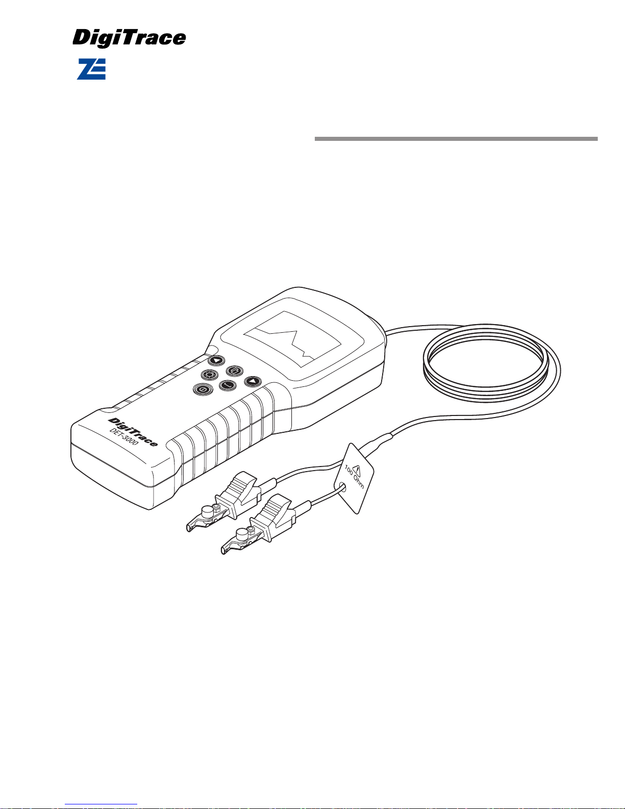
1. DET-3000 cable fault locater
The DET-3000 cable fault locater can be used to locate many types of electrical fault to almost
any type of electrical cable, including heating cables, caused by mechanical damage during
installation, maintenance and use. The DET-3000 quickly and easily locates these spots of trouble without requiring the high cost of thermal insulation removal and replacement. The damaged section of cable can be repaired with a minimum of disruption to the remainder of the
installation. The DET-3000 is shipped in a rigid carrying case and comes complete with 100
Ohms test leads preinstalled and an extensive user manual. The DET-3000 uses the principle of
time domain reflectometry (TDR) to locate cable faults. The DET-3000 can locate major or
minor cabling problems including; sheath faults, broken conductors, water damage, loose connectors, crimps, cuts, smashed cables, shorted conductors, system components, and a variety
of other fault conditions. In addition, the DET-3000 can also be used to assist in inventory management to test reels of cable for shipping damage, cable shortages and cable usage. The speed
and accuracy of the DET-3000 makes it the preferred method of cable fault location.
The DET-3000 cable fault locater is derived from the Bicotest limited Lexxi™ T810 cable fault
locator. As such all user recommendations and technical specifications listed in the Bicotest
Lexxi™ T810 user manual (00901274-2) are applicable to both product types. Tyco Thermal
controls will not supply any of the accessories listed in that manual. DET-3000 is a trademark of
Tyco Thermal controls. Lexxi is a trademark of Bicotest Limited.
2. Principles of operation
Time domain reflectometers, such as the DET-3000, work on the same principle as radar. A
pulse of energy is transmitted down the cable. When that pulse reaches discontinuity, such as
the end of the cable, or a fault along the cable, part or all of the pulse energy is reflected back
to the instrument. The DET-3000 measures the time it takes for the signal to travel down the
cable, see the discontinuity, and reflect back. The DET-3000 then converts this time to distance
and displays the information as a waveform and/or distance reading.
3. Impedance
Any time two metallic conductors are placed close together, they form a cable impedance. The
DET-3000 looks for a change in impedance which can be caused by a variety of circumstances
such as: cable damage, water ingress, change in cable type, improper installation, and even
manufacturing flaws.
The insulating material that keeps the conductors separated is called the cable dielectric. The
impedance of the cable is determined by the spacing of the conductors from each other and the
type of dielectric used.
The DET-3000 sends electrical pulses down the cable and samples the reflected energy. Any
impedance change will cause some energy to reflect back toward the meter and will be displayed. How much the impedance changes will determine the amplitude of the reflection.
4. Propagation velocity factor (pvf)
The DET-3000 is an extremely accurate instrument. However, variables in the cable itself or the
path along which the cables are laid out sometimes cause errors in distance measurements.
One way to minimize error is to use the correct Velocity of Propagation (pvf) of the cable under
test. The pvf is a specification of the cable indicating the speed at which a signal travels down
the cable. Different cables have different pvf. In order to assure the most accurate distance
measurements the cable pvf must be known.

3
4.1 Pvf defined:
The speed of light in a vacuum is represented by the number 1 (100%). All other signals are
slower. A cable with a pvf of .85 would transmit a signal at 85% of the speed of light. The pvf of
a cable is determined by the dielectric material that separates the two conductors. By entering
the correct pvf, the instrument is calibrated to the particular cable. Typically, the pvf of the cable
under test will be listed in the cable manufacturer's catalogue. (see table, chapter 7. of this document or point your internet browser at: www.tycothermal.com for the most recent version of
this document. In case the pvf of the cable under test is not known it must be determined using
the procedure below.
4.2 Determining the propagation velocity factor of unknown cable types
Simply measure a length of good cable (no faults) and change the DET-3000´s pvf setting until
the display shows the same distance reading as the measured length. If no good cable is available, the distance to the fault can be measured from both ends of the cable using an arbitrary
pvf (the same must be used at each end). The actual distance to the fault can be calculated as
in the following example:
Total cable length = 250 m (from records or measured)
Distance measured from first end = 90 m
Distance measured from second end = 140 m
Actual distance from first end =
If required, the instrument can then be reconnected at the first end and the pvf adjusted until
the indicated distance is 97.8 m. This value of pvf can then be noted and used for subsequent
fault location on the same type of cable.
It is also important to know that the velocity factor of a cable can change with temperature and
age. It can also vary from one manufacturing run to another. Even new cable can vary as much
as ± 3%.
5. Use common sense
Although a thorough understanding of time domain reflectometry and the measuring instrument
is vital to successful troubleshooting, there is never a substitute for good common sense. If
your DET-3000 indicates a distance of 150 meter to a fault, but there is evidence that a forklift
ran into the pipe at 162 meter, there is a pretty good chance that the fault was caused by the
accident. Familiarity develops versatility. The more you use the DET-3000, the more confident
and comfortable you will become, and the more applications you will find for it.
6.
Locating faults on heat tracing systems
using the DET-3000
The DET-3000 comes with 100 OHM test leads preinstalled NEVER USE THE DET-3000 on
cables connected to the mains supply. Besides the live hazard the voltages at mains level
exposed to the inputs will cause severe damage to the unit.
Prior to each measurement verify that the complete installation is isolated from the mains supply. Disconnect the heating cable from the connection terminals at the power connection. It is
important that all measurements are performed directly at the heating cable to avoid mis-readings due to power cable used to bring the power to the heating cable. Cold leads permanently
joined with the heating cable, as is the case with MI or other types of series heaters, do not
have to be removed. The final distance readout will have to be adjusted by subtracting the
length of the cold lead.
Connect the leads of the DET-3000 to the cable under test. One lead goes to the conductors,
twisted together in a pig tail, and the other to the braid. Select the appropriate pvf (propagation
velocity factor) from the table (see section 7) depending on the heating cable under test (see
table). Refer to section 4.2 of this manual to determine the pvf of unlisted cables or from cables
from which the pvf is not known.
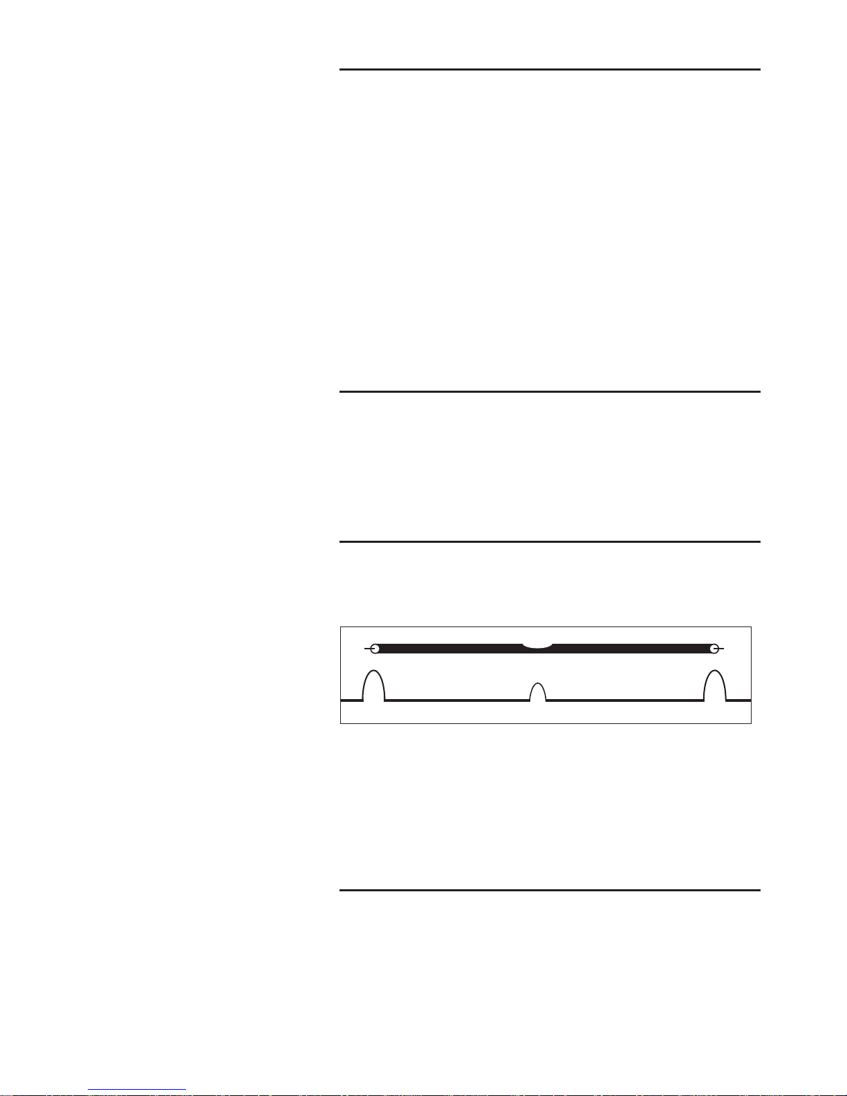
Select a measuring range exceeding the expected length of the circuit under test. The end of the
cable, or a severe cable fault, is seen on the unit display as a deflection from the horizontal line
across the middle of the screen (in case of doubt start off from the Max range of 3000 m).
Examine the trace for any deflections from the horizontal line after the transmit pulse. Examine
the trace from the left to the right, moving the cursor along the horizontal line to the edge of the
first significant deflection seen. Set the cursor at one pixel to the left of the deflection and read
90
(90 + 140)
X 250 97.8 m
_
~
4
the distance. Subtract 1.3 meter from the displayed result for the measuring leads.
Interpretation of the trace information is straightforward. A rising deflection indicates an open
circuit, a high series resistance, or a transition to a cable having higher characteristic impedance. A falling deflection indicates a short circuit, a "Tee" joint (tap) or a transition to a cable
with lower characteristic impedance. Shorts and opens will show full screen deflections whilst
poor connections or slight discontinuities give much smaller deflections. If no deflections are
seen there may be no fault or the fault is beyond the range displayed or beyond the instruments
sensitivity. If it appears there is a fault near to or within the transmitted pulse select the next
lower range. For examples of the traces which may be seen during investigation refer to the
Lexxi T810 user manual on the inside front cover.
The principle of taking measurements with the DET-3000 is the same regardless of the type of
fault you are looking for. On branched systems the measurement will have to be repeated on
each section of the circuit. Therefore splice or marshalling boxes will have to be opened and the
heating cable will have to be disconnected from the terminals in order to be investigated using
the DET-3000.
Cabel type
DET3000
Selfregulating
3BTV2-CT 0,48
5BTV2-CT 0,48
8BTV2-CT 0,41
10BTV2-CT 0,40
4XTV2-CT 0,59
8XTV2-CT 0,56
10XTV2-CT 0,57
12XTV2-CT 0,56
15XTV2-CT 0,58
20XTV2-CT 0,55
10QTV2-CT 0,39
15QTV2-CT 0,39
20QTV2-CT 0,4
5KTV2-CT 0,58
8KTV2-CT 0,55
15KTV2-CT 0,54
20KTV2-CT 0,51
WGRD-FS-A-2X 0,44
WGRD-FS-B-2X 0,43
WGRD-FS-C-2X 0,4
HWAT-L 0,41
HWAT-R 0,41
HWAT-M 0,42
FROSTOP BLACK 0,50
FROSTOP GREEN 0,51
FREEZGARD W51 0,47
FREEZGARD W52 0,49
FREEZGARD W53 0,48
LC2-5LC2-CT 0,51
EM-EM2-R 0,39
EM-EM2-XR 0,40
8STV 0,42
10STV 0,44
Cabel type
DET3000
MI
EMK CuNi 400 0,36
HDF 1M 250 0,38
HDC 1M4 0,48
1H63 0,38
1H2,5 0,42
1H1,5 0,48
1H4 0,43
323/1 0,55
30/38C 0,35
41/200K 0,37
446CC 0,48
HCC 1M11 0,48
MHC 40 0,42
1M4 0,42
MIN-M1-4 0,38
MIN-M1-17 0,39
MIN-M1-63 0,40
7001-0048 0,62
Cabel type
DET3000
Power limiting
5VPL2-CT 0,70
10VPL2-CT 0,68
15VPL2-CT 0,66
20VPL2-CT 0,64
IHT/2/10-CT 0,64
IHT/2/20-CT 0,64
IHT/2/30-CT 0,65
FHT/2/10-CT 0,65
FHT/2/20-CT 0,65
FHT/2/30-CT 0,59
Cabel type
DET3000
Series
LLP-1 0,60
LLP-2 0,61
LLP-3 0,59
LLP-4 0,59
LLP-5 0,59
FCW-T1,8 0,69
ICW-T2,9 0,69
ICW-T7,0 0,70
FCW-T10 0,67
ICW-T10 0,67
FCW-T15 0,67
ICW-T15 0,67
FCW-T17,8 0,68
ICW-T17,8 0,68
FCW-T25 0,68
ICW-T25 0,68
FCW-T50 0,65
ICW-T50 0,65
FCW-T68 0,68
ICW-T68 0,68
FCW-T100 0,69
ICW-T100 0,69
FCW-T200 0,66
ICW-T200 0,66
FCW-T370 0,68
FCW-T500 0,66
ICW-T500 0,66
FCW-T730 0,67
ICW-T730 0,67
FCW-T1000 0,65
ICW-T1000 0,65
EXEC 15 Ohm
EXEC 100 Ohm
EXEC 200 Ohm
PNG 180 Ohm
BKG 180 Ohm
KNG 240 Ohm
Tes-65-FOJ
Cable type
DET3000
Power cable
YMvK 3x2,5 0,57
YMvkK 6x1,5 0,56
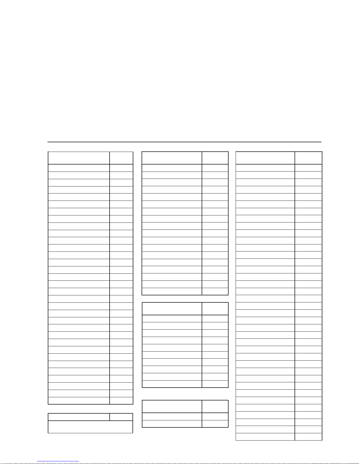
7. Table Propagation velocity factors (pvf) of heating cable types
Cable type DET-3000
Use for XPI the same factor as
you would use for FCW / ICW
 Loading...