

Digitimer NeuroLog NL822, NeuroLog NL824 User Manual
Users Manual NeuroLog™ System NL822/824
NL822 - 2-Channel AC Pre-Amplifier
NL824 - 4-Channel AC Pre-Amplifier
Multi-Channel, AC coupled, Miniature Low Noise Amplifiers
Introduction
The NL820A ISOLATOR is the module at the heart of the NeuroLog™ System Isolated Amplifier range of
components that meet, or exceed, the BS5724 and IEC601-1 patient leakage specifications.
The NL822 and NL824 miniature, low-noise, AC coupled (or NL832/834 DC) pre-amplifiers complete the
system.
General Description
x100
x1K
x10K
10Hz
3Hz
30Hz
Digitimer Ltd
1
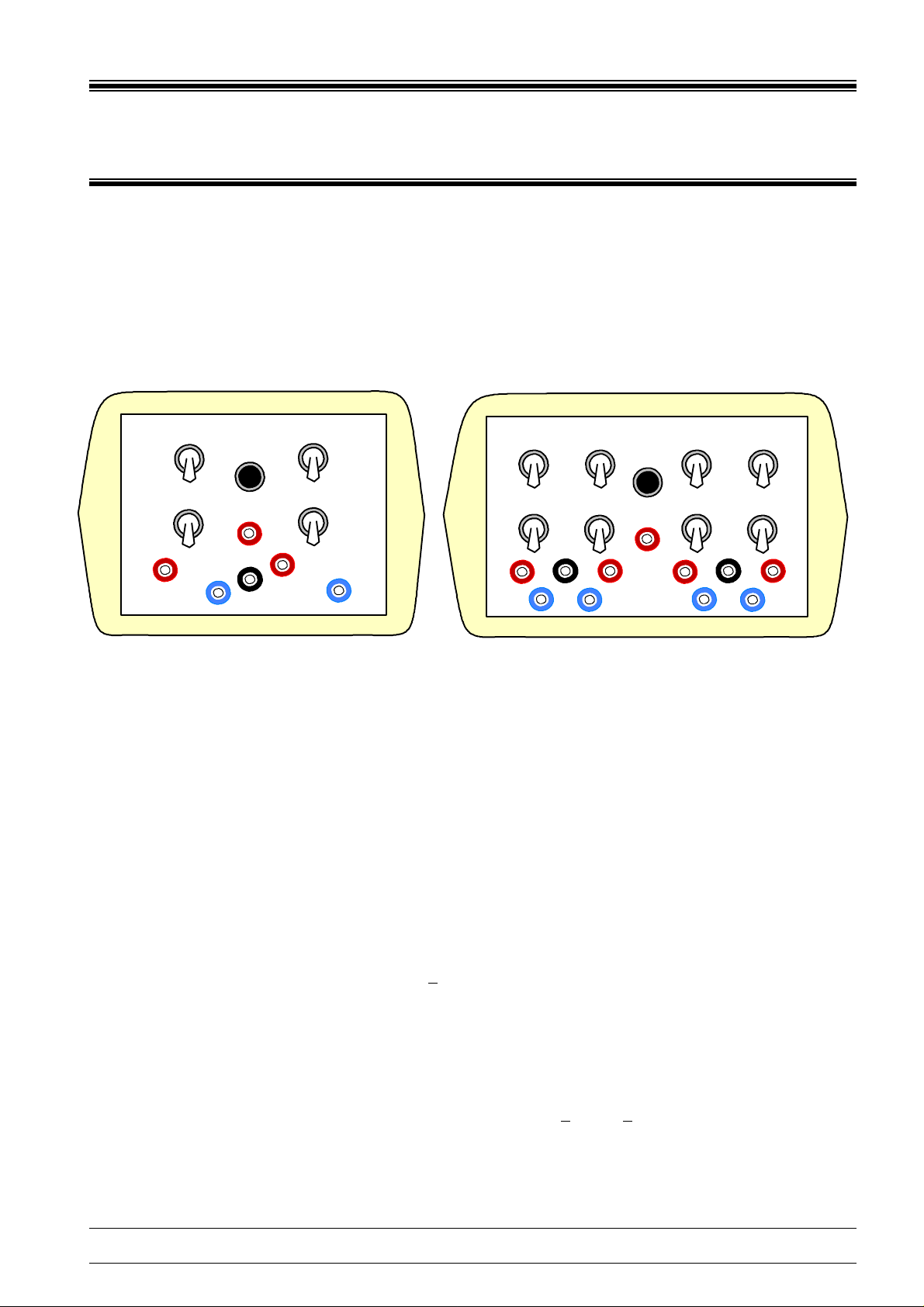
NL822
MUTE
CAL
COM
x100
x1K
x10K
10Hz
3Hz
30Hz
2
x100
x1K
x10K
10Hz
3Hz
30Hz
COM
1
NL824
MUTE
CAL
2
Digitimer Ltd
x100
x1K
x10K
10Hz
3Hz
30Hz
COM
3
4
The NL822 and NL824 units are low noise differential AC pre-amplifiers with simple three step control of gain
and low frequency cut-off point. High frequency response extends to 30kHz and no control of cut-off point is
provided. The designs provide high common mode rejection of signals from DC to frequencies in excess of
1kHz.
The NL822 AC Pre-Amplifier provides two differential amplifier channels with a common terminal and a
built-in 100 microvolt calibration signal.
The NL824 AC Pre-Amplifier has four differential amplifier channels referenced to a common terminal with
100 microvolt calibration facility.
Both units have a mute facility for suppression or reduction of overload artefact signals. This can either be
operated by a push button on the front panel or, when used with the NL820A ISOLATOR, triggered from an
electrical signal to provide an automatic mute feature.
Power supply to either unit will normally be provided by an isolated supply system within the NeuroLog
NL820A ISOLATOR module from supply rails of +13 volts nominal. A 9-way plug fitted to a three metre length
of cable provides for supplies, channel outputs and remote mute control.
Stand-alone use
The NL822 and NL824 will operate from DC supplies in the range +10V to +15V but it must be remembered
that the unit will not isolate the signals unless a specific isolation stage is used.
Digitimer Ltd Page 1 of 4 Copyright © 1992-8
E-mail: sales@digitimer.com Tel:+44 (0)1707 328347; Fax:...373153 Website: www.digitimer.com

Users Manual NeuroLog™ System NL822/824
Specification
Gain
x100, x1000, x10,000 selected by 3 position toggle switch each channel separately adjustable. When used
with the NL820A module with its 1:2:5 sequence gain control the full range covered will be x100 to x50,000 in
9 steps i.e. 10mV/V to 20µV/V.
Low Frequency
These amplifiers are AC coupled to remove electrode potentials and selection by 3 position toggle switch
provides 3Hz, 10Hz and 30Hz cut-off frequencies. The amplifiers will operate with dc input differential voltages
up to 200mV from the electrodes and common mode voltages in excess of 1 volt without affecting their AC
performance.
Input Impedance
100M ohms each input to common.
Common Mode
The differential inputs provide a rejection ratio greater than -80dB (10,000:1) for frequencies up to 1kHz. Note
when used with the NL820A ISOLATOR module signals present between mains ground and the NL822/824
input system are further reduced to give common mode rejection ratios greater than -120dB.
High Frequency
No adjustment of high frequency range is provided, the -3dB point is greater than 30kHz. When used with the
NL820A module the overall system response reduces, but the -3dB is still greater than 10kHz. For adjustable
bandwidth control the NL125/126 filters can be connected to the NL820A outputs.
Noise
When operated with inputs short circuited, over the full 30kHz bandwidth the noise is less than 5µV RMS. The
low frequency noise from 3-100Hz is less than 1.5µV peak to peak.
Deblock/Mute
Operated by manual push button or remote logic trigger control through the NL820A. May be used to inhibit
stimulus artefact effects - mute time adjustable over the range 1-10 milliseconds.
Calibrate
A square wave pulse is available from a front panel socket of 100µV amplitude at approximately 160Hz.
Connection
The amplifier channel inputs are 2mm sockets coloured red and blue to indicate relationship between input and
output as follows. A positive input at the red socket will produce a positive output, a signal at the blue input will
be inverted. The common signal return socket is coded black. Where a single ended input signal is to be
amplified, then the un-used input (red or blue) socket should be linked to the common black socket.
Calibration
The 100 microvolt calibrate signal can be connected to any amplifier channel by linking from the calibrate
socket to the appropriate red or blue input socket. The other input should be connected to the COMMON
socket.
Digitimer Ltd Page 2 of 4 Copyright © 1992-8
E-mail: sales@digitimer.com Tel:+44 (0)1707 328347; Fax:...373153 Website: www.digitimer.com
 Loading...