

Page 1

DigiGuard™ Door Alarm
Installation and Operation Guide
World Class Security Solutions
Page 2

Page 3

Chapter 2
Installing the Door Transmitter
Included in this Chapter
Introduction............................................................................
Mounting the Door T ransmitter and Magnet......................
Battery Connection and Replacement .................................
CAUTION: Changes or modifications not expressly approved by the party
responsible for compliance could void the user’s authority to operate this
equipment.
Description of Door Transmitter
Roll-Up Doors
Garage Type Panel Roll-Up Doors
Swing Doors
Installing the Battery
Replacing the Battery
Page 4
2 - 2 Installing the Door Transmitters
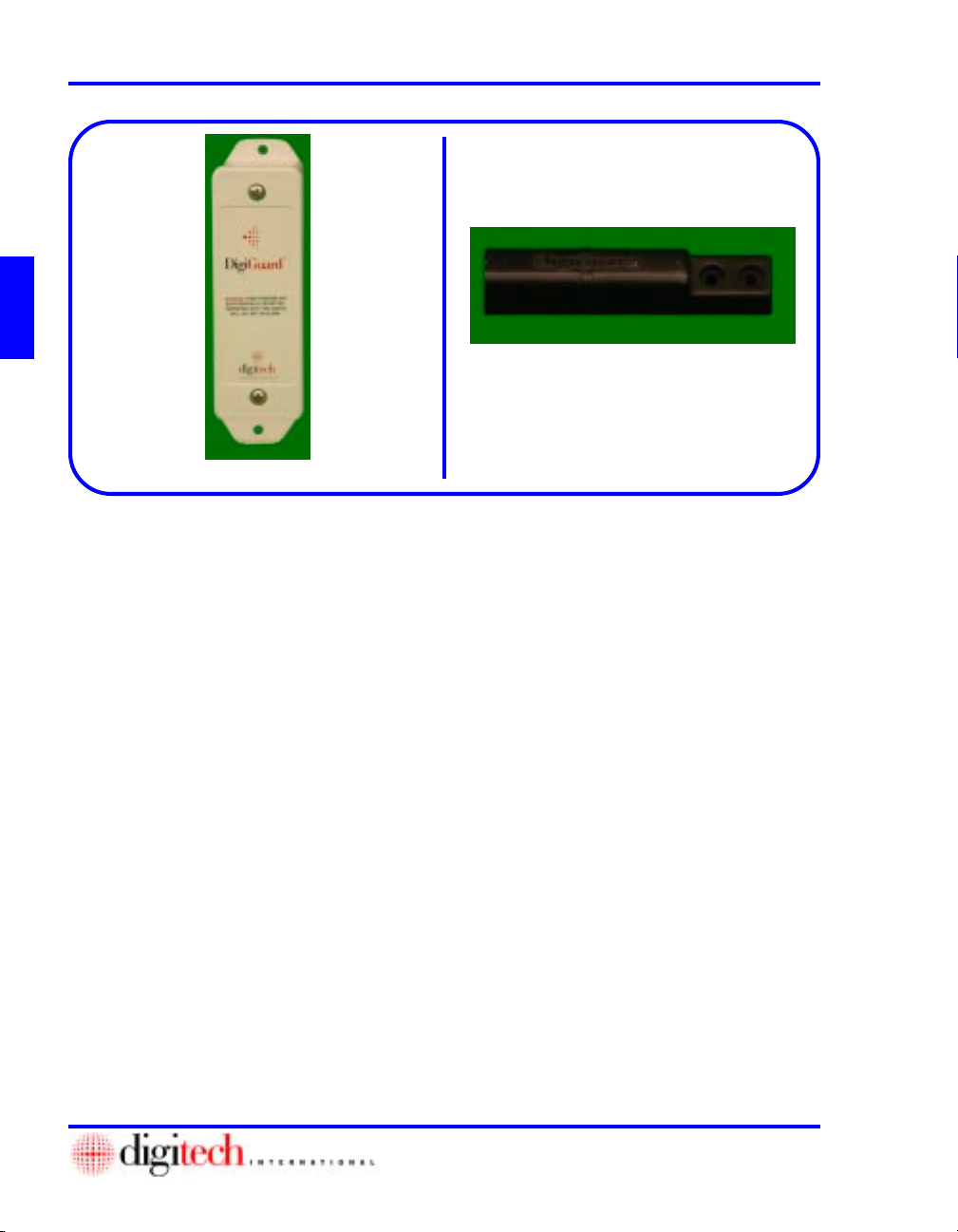
Figure 2-2
Figure 2-1
Introduction
The Door Transmitter, Figure 2-1, is housed in an environmental plastic enclosure. The enclosure has
been designed for outdoor use, and has a UV inhibitor in the material. The enclosure is also moisture
sealed with a gasket between the cover and case of the enclosure.
The Door Transmitter is equipped with a tamper switch. Removing the cover of the Transmitter or placing
another magnet near the case will trigger the tamper alarm.
The Transmitter must be mounted on the door frame with the Magnet, Figure 2-2, mounted on the door.
The proper alignment of these two components will ensure that the reed switch array will operate correctly
when the door is opened and the Magnet moves away from the Transmitter. Proper orientation of the door
switch will also ensure that the antenna is oriented correctly for maximum antenna gain. The magnet is a
heavy duty design which allows for greater tolerance, preventing the possibility of false alarms from minor
movements of the door.
The Transmitter/Magnet assembly should be mounted on the opposite side of the door from the door hasp
on a roll-up door to avoid hitting the Transmitter with the hasp. On swing doors, mount the Transmitter/
Magnet assembly on the opposite side of the door from the hinges to provide adequate separation of the
Magnet on opening of the door. Mounting is shown on the left of a roll-up door since most hasps are
mounted on the right. On swing doors, the mounting is shown on the right since most hinges are on the
left.
If the facility’s configuration is different, rotate the entire assembly, Transmitter and Magnet, keeping the
orientation of the Magnet and Transmitter the same.
NOTE: If the site has garage type doors or other non standard doors, or any damaged doors or frames, notify
Digitech International, Inc. at 800.523.9504, or contact the Reseller for specific instructions before attempting to install this system.
Page 5

2 - 3DigiGuard™ Door Alarms Installation and Operation Guide
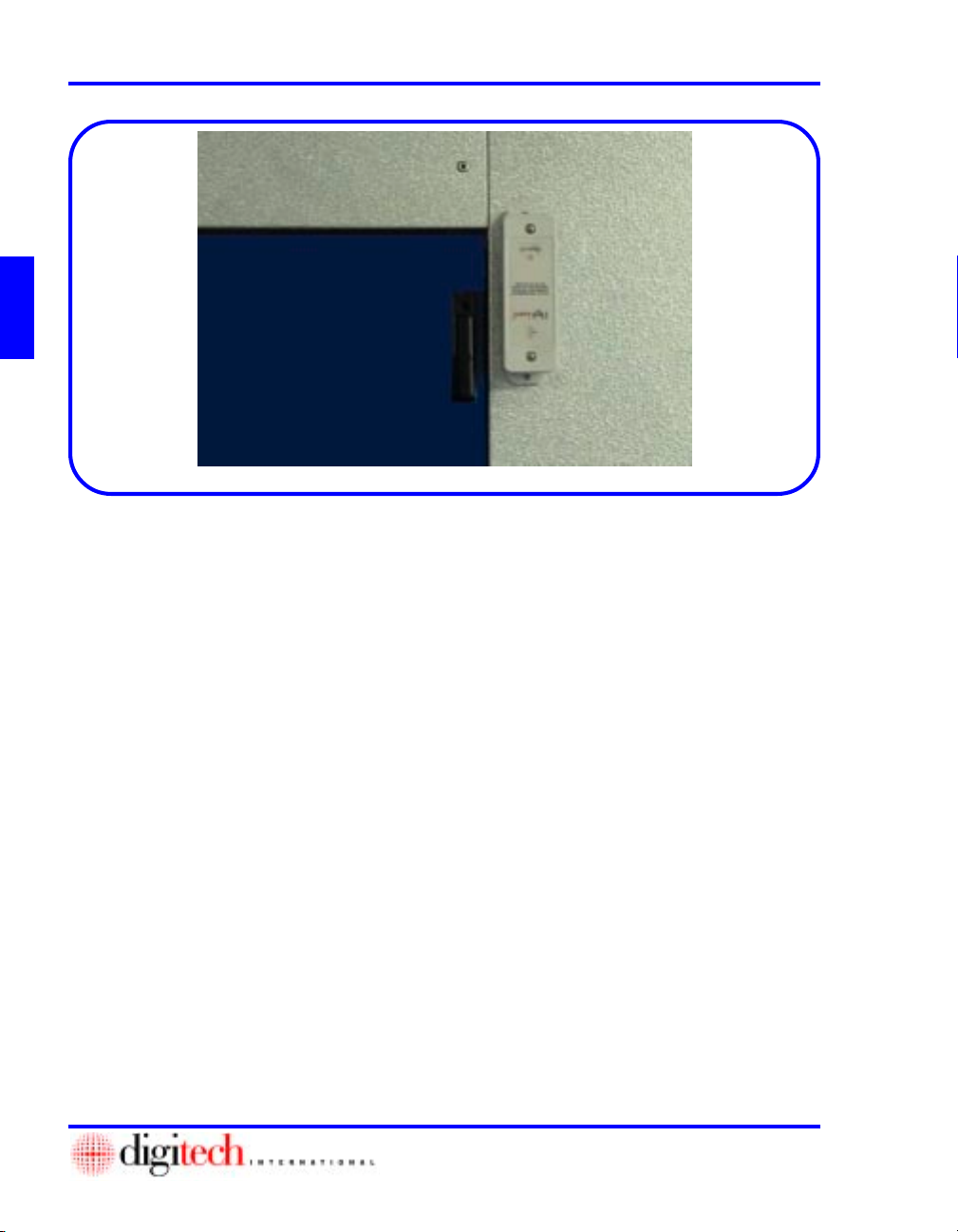
Figure 2-3
Mounting the Door Transmitter and Magnet
Roll Up Doors
1. When installing the Door Transmitter on roll
up doors, it should be mounted vertically in
the upper left corner of the door jamb. The
Magnet is mounted horizontally on the door
and aligned with the ridge on the Transmitter
case. Figure 2-3
2. The Magnet mounts horizontally in a recess on
the corrugated door to provide clearance when
the door rolls up. Figure 2-3
Figure 2-4
3. Use the DigiGuard™ mounting template (P/N
1420-200) for placement and marking of the
holes to mount both the Transmitter and the
Magnet. Figure 2-4
4. Place the larger vertical bar on the door frame
with the horizontal smaller bar in one of the
recesses on the door approximately 3” below
the top of the door frame.
Note: If the door hasp is mounted on the left
side of the door, invert the mounting template
and use it upside down on the right side of the
door. The bar in the recess will be lower on
the door than stated in Step 4.
5. Mark all holes and remove the template.
Page 6

2 - 4 Installing the Door Transmitters
Figure 2-5
Figure 2-6
6. Center punch all the marks to keep the drill
from walking off the marks.
7. Drill the holes for the Magnet with a 11/64”
bit. Figure 2-5
CAUTION: DO NOT use the Magnet as a
template for the drill. The close tolerance
on these rivet holes is to insure a stable
mounting of the Magnet to the door.
Drilling through the rivet holes in the
Magnet will enlarge them and leave the
Magnet less than ideally secure and stable.
8. Place a rivet (Digitech P/N 2840-008,
supplied) in each hole on the Magnet and
place it through the drilled hole in the door.
9. Finish securing the Magnet with the rivets.
Figure 2-6
Note: Figure 2-6 shows the proper mounting
of the Magnet for optimum performance. The
vertical ridge down the center of the Magnet
should be aligned in the center of the Transmitter case.
The Magnet has been designed to be easily
mounted on existing doors. The rivet holes are
located on the right so the Magnet can be
mounted with minimum effort. The rivet holes
on the Magnets have very close tolerances to
provide tight, stable installation. Do not
substitute the size of the rivets shipped with
the Magnets and do not use the Magnet as a jig
for drilling.
Page 7

2 - 5DigiGuard™ Door Alarms Installation and Operation Guide
Figure 2-7
10. If mounting the Transmitter on an aluminum or
wood surface, drill the holes using a 9/64” bit.
If the mounting surface is not metal or wood,
drill the hole 1/4” to hold an appropriate
anchor (not supplied) for the #8 screw.
Figure 2-7
Figure 2-8
11. Record the Serial Number of the Transmitter
and the unit number for later entry into the
DigiGate-700™ software. See Appendix B
12. Secure the Transmitter using the #8 x 3/4”
screws supplied with the case. Figure 2-8
Page 8

2 - 6 Installing the Door Transmitters
Figure 2-10
Figure 2-9
NOTE: Placing the Magnet closer than 1/
2” to the Transmitter will affect the tamper
alarm. The Magnet should be from 5/8” to
3/4” from the Transmitter when the door is
fully closed.
13. Figures 2-9 and Figure 2-10 show the
completed installation.
Page 9
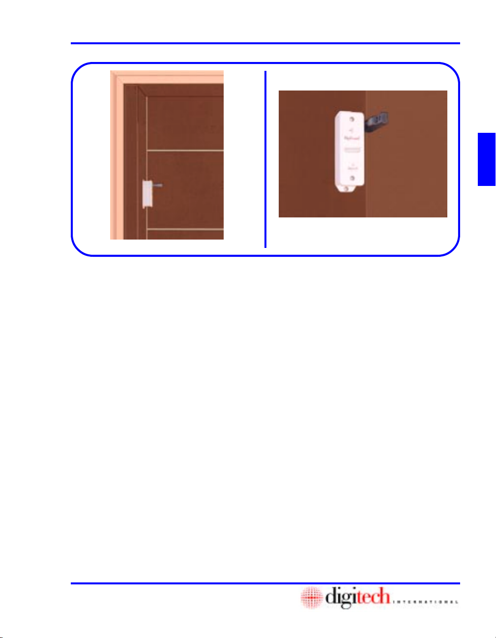
Figure 2-11
Garage Type Panel Roll-Up Doors
1. Installing the Door Transmitters on garage
type panels is the same as standard roll-up
doors with the Transmitter and Magnet on the
opposite side from the door hasp.
NOTE: If the door hasp is mounted on the
left side of the door, mount the Transmitter
upside down on the right side of the door as
in the standard roll-up door installation.
The differences are:
2. The Transmitter and Magnet should be
mounted in the vertical center of a panel to
prevent knocking the Magnet off the door
when it is raised. Mounting it near the top or
bottom edge of the panel will bring it too close
to the top of the door frame when the door is
rolled up. Figure 2-11
2 - 7DigiGuard™ Door Alarms Installation and Operation Guide
Figure 2-12
3. The Magnet cannot mount behind the door
frame as it did on the standard roll up door.
4. Since less of the magnet is positioned behind
the Transmitter, the magnetic strength is less
and the Transmitter should be mounted with a
gap about 1/4” less than a standard roll-up
door. Figure 2-12
NOTE: The Transmitter should be
approximately 1/2” to 5/8” from the Magnet
and should be tested to insure correct
operation.
Page 10
2 - 8 Installing the Door Transmitters
Figure 2-13
Swing Doors
When installing the Door Transmitter on swing doors, the T ransmitter should be mounted
vertically and inverted (upside down for the right side door frame) or in its standard configuration
for the left side door frame.
The Transmitter and Magnet should be mounted on the side of the door opposite from the hinges
(the latch side). The gap between the Transmitter and the Magnet should be 1/2 inch and as close
to the top of the door as possible.
The ridge on the Magnet should align about 1/4” above (toward the center of the transmitter) the
ridge on the Transmitter case.
Mounting the T ransmitter and Magnet
1. Mount the Transmitter vertically at the
upper corner of the door frame, as stated
above, opposite the hinged side of the
door. The edge of the case should be
approximately 1/4” from the edge of the
door frame.
2. The Magnet is mounted vertically on the
door with the ridge alignment for the
Magnet/Transmitter case as stated above.
Figure 2-13
3. The gap between the Magnet and the
Transmitter case should be 1/2”.
4. Place the Transmitter housing as shown in
Figure 2-13
5. Use the holes in the flanges as a template,
mark the holes for the mounting screws.
6. Drill these holes using a 9/64” bit.
7. Record the Serial Number of the Transmitter and the unit number for later entry into
the DigiGate-700™ software.
8. Secure the Transmitter using the #8 x 3/4”
screws supplied with the case.
9. Place the Magnet in the proper position
and mark the holes.
10. Drill using an 11/64”.
11. Place a rivet (Digitech P/N 2840-008,
supplied) in each hole on the Magnet and
place it through the drilled hole in the
door.
12. Finish securing the Magnet with the rivets.
NOTE: Do NOT drill through the
mounting holes on either Magnet or
Transmitter.
Page 11

2 - 9DigiGuard™ Door Alarms Installation and Operation Guide
Figure 2-14
Figure 2-15
Figure 2-17 Figure 2-18
Figure 2-16
Battery Connection and Replacement
The DigiGuard™ system uses a custom lithium battery pack. The battery is rated for a minimum
operational life of ten years. The lithium battery ensures long life of the Door Transmitter over
wide temperature ranges. Using an alkaline or a non-approved battery can damage the Door
Transmitter and will void the warranty. The battery is installed from the factory. The following
instructions are provided for installing as well as changing the battery. Always disarm the system
before doing any work on the system.
Installing the Battery
1. Remove the screws from the Transmitter cover.
2. Remove the cover.
3. Plug the connector from the battery to the pins
on the Transmitter board. Figure 2-14
4. Place the battery in the case above the top
holding pin. Figure 2-17
5. Replace the cover and secure with the screws
removed in Step 1. Figure 2-18
NOTE: Pay attention to the orientation of the
battery connector. The battery will only
connect in one direction. Forcing the battery
connector onto the pins can damage the Board.
Also, pay attention to the orientation of the
cover with the case. Align the ridge on the top
right of the cover with the ridge on the case.
Putting the cover on backwards can damage
the Transmitter Board.
1. Remove the screws from the Transmitter cover.
2. Remove the cover.
3. Unplug the battery’s connector from the two
4. Replace the old battery with the new Digitech
5. Place the battery in the case above the top
6. Replace the cover and secure with the screws
Replacing the Battery
pins on the Transmitter Board.
Figure 2-15
replacement battery, connecting the plug on
the pins. Figure 2-16
holding pin and mount with wires toward the
antenna. Figure 2-17
removed in Step 1. Figure 2-18
NOTE: Do not recharge, disassemble, or
dispose of in heat above 212 deg. F. Replace
only with Digitech P/N 1420-1015. May
present fire or burn hazard if mistreated.
Page 12

2 - 1 0 Installing the Door Transmitters
This Page Left Blank Intentionally
 Loading...