

Digitax F2, F2RTC Technical Manual

Technical Manual
F2 and F2RTC versions
V 1.2

2
Introduction
About this Manual
The F2 Taximeter is designed to be, at the same time, easy to use and extremely powerfull.
This manual is conceived to be user friendly, more graphical and easy to understand.
In the first section are described the electrical connections, the ways to fix and lead the taximeter, how to
assemble the sensor box.
The second section explain the meter’s operative modes, the functions and the programming phase (Autotest,
Statistical Memory).
The third sections contains the description of all the tariff programming parameters.
Index
Introduction ..................................................................................................................................................... 2
About this Manual .......................................................................................................................................... 2
Electrical Connections Table ............................................................................................................................. 3
Connectors - Pins Out ....................................................................................................................................... 4
How to Fix the Taximeter ................................................................................................................................. 5
Fixing Plate ......................................................................................................................................................... 5
Movement Sensor: ........................................................................................................................................... 6
How to Assemble ................................................................................................................................................ 6
How to Seal the Taximeter ............................................................................................................................... 7
Regular Way of Sealing the Taximeter ............................................................................................................... 7
Special Way of Sealing ................................................................................................................................... 7
For Hire-Stopped-Hired .................................................................................................................................... 8
The Operative Mode........................................................................................................................................... 8
“K” Constant .................................................................................................................................................... 9
(Car Transmission Ratio) ..................................................................................................................................... 9
Time and Date Setting .................................................................................................................................... 10
How To Set The Taximeter’s Time And Date .................................................................................................... 10
Statistical Memory ......................................................................................................................................... 11
How to Read the Statistical Memory Content .................................................................................................. 11
How to read the memory blocks information .............................................................................................. 11
Statistical Memory ......................................................................................................................................... 12
How to Print the Statistical Memory Content .................................................................................................. 12
Statistical Memory ......................................................................................................................................... 13
How to Erase the Statistical Memory Content ................................................................................................. 13
The information contained here are property of DIGITAX Automotive Electronics Italy, and extremely confidential. Any disclosure, cop ying, distribution to third
party is strictly prohibited.

3
Electrical Connections Table
PRINTER
TRANSDUCER
GREY (F)
VIOLET (G)
GREEN (H)
YELLOW (J)
Max. 3 watts
(*)
WHITE
PINK
Fuse 2 A
PASSENGER TOOL
Warning!
The taximeter is not provided with his own set
of fuses. You must install them by yourself
following the scheme. You will be responsable
for every damage that you can cause for the
omission of these fuses.
Digitax rejects every legal responsability.
Fuse 2 A
RED
RED
Fuse 2 A
Car Lights Switch
+ 12 V
BROWN
BLACK
Max. 25 watts
The information contained here are property of DIGITAX Automotive Electronics Italy, and extremely confidential. Any disclosure, copying, distribut ion to third
party is strictly prohibited.
4
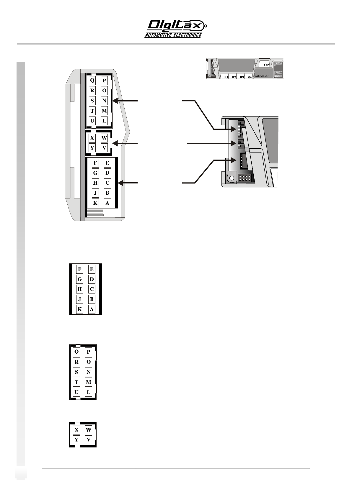
Connectors - Pins Out
LEGENDA
POWER SUPPLY - connections:
A INPUT BATTERY + 12 VOLTS
B INPUT PASSENGER DETECT SENSOR
C INPUT +12 VOLTS CAR LIGHTS
D INPUT GROUND ( CAR BODY )
E 12 VOLTS (ROOF TOP LIGHT) Max 3 A
F 12 VOLTS POWER OUTPUT (LIGHT 1 ) Max 1 A *
G 12 VOLTS POWER OUTPUT (LIGHT 2 ) Max 1 A *
H 12 VOLTS POWER OUTPUT (LIGHT 3 ) Max 1 A *
J 12 VOLTS POWER OUTPUT (LIGHT 4 ) Max 1 A *
K INPUT BATTERY +12 VOLTS
PERIPHERICALS - connections:
L GROUND
M TXD 2 RS 232 COM 2 TX
N RXD 2 RS 232 COM 2 RX
O AUX 2 INPUT/OUTPUT
P AUX 1 INPUT/OUTPUT
Q PIO 1 INPUT/OUTPUT
R + 12 VOLTS
S PIO 2 INPUT/OUTPUT
T RXD 1 RS 232 COM 1 RX
U TXD 1 RS 232 COM 1 TX
TRANSDUCER - connections:
V INPUT 2
W GROUND
X + 12 VOLTS
Y INPUT 1 ( SENSOR )
*Optional Hardware
LEFT VIEW
TRANSDUCER
CONNECTOR
POWER SUPPLY
CONNECTORS
PERIPHERICAL
CONNETTORS
The information contained here are property of DIGITAX Automotive Electronics Italy, and extremely confidential. Any disclosure, cop ying, distribution to third
party is strictly prohibited.
5
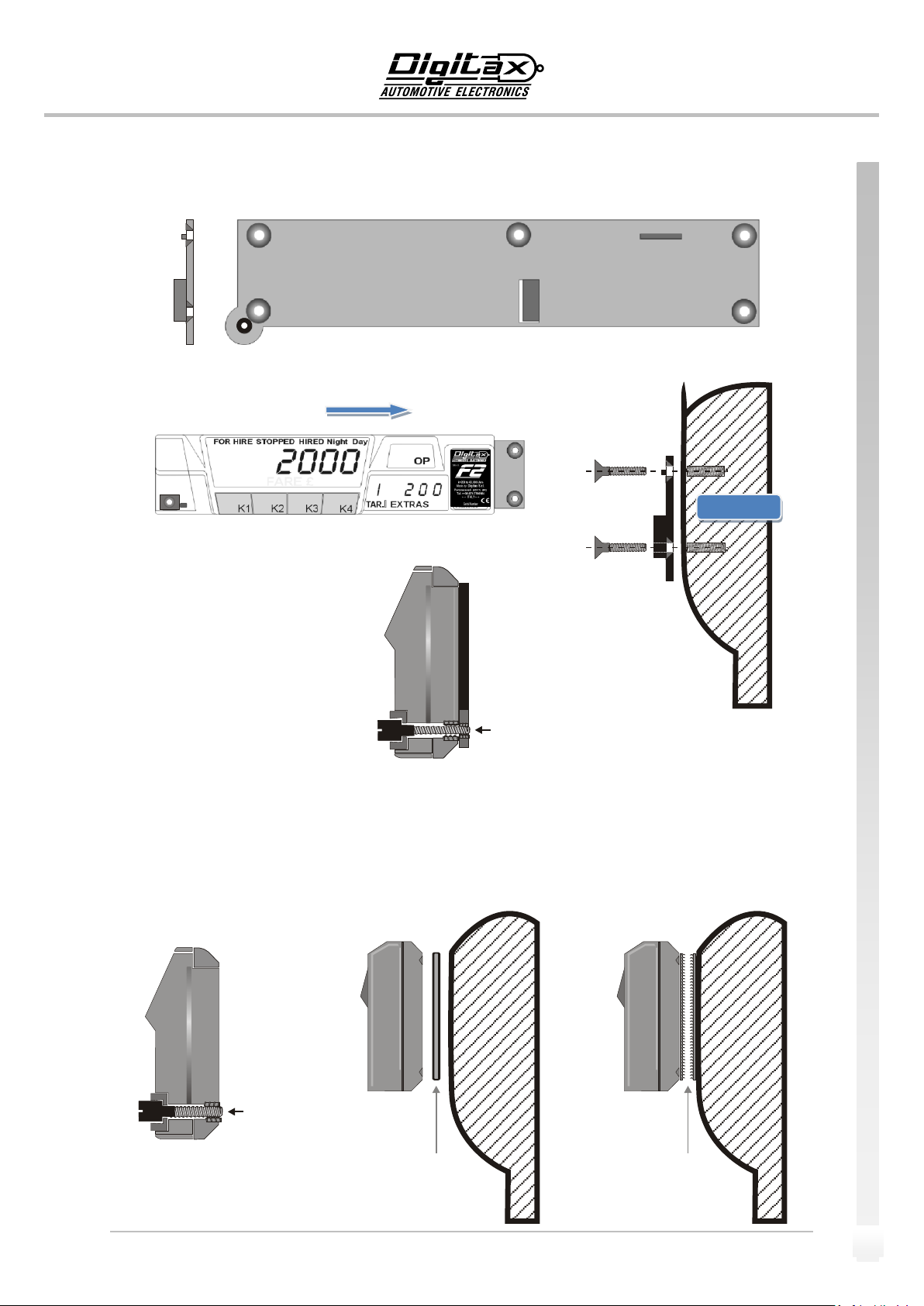
How to Fix the Taximeter
Screw 3MA
7x29,5 mmm
Front View
Fixed the bracket
Locking direction
Dashboard
Screw 4MA
7x26 mmm
Sealed to the
taximeter
BY A DOUBLE SIDE
GLUED TAPE
BY A VELCRO
STRAP
Fixing Plate
The information contained here are property of DIGITAX Automotive Electronics Italy, and extremely confidential. Any disclosure, copying, distribut ion to third
party is strictly prohibited.
6
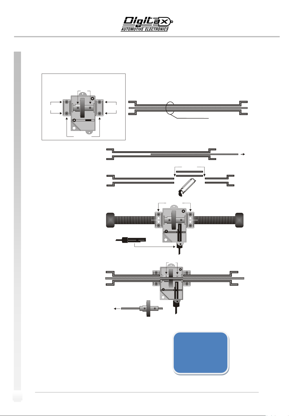
Movement Sensor:
SENSOR
Screws B
Screws A
Screws B
Clamps
Sheathing
Speedometer
Cable
1) Take out the internal wire
from the sheathing.
2) Shorten the sheating 36
m/m
3) Insert both ends of the
sheathing in the clamps and
tight the 4 screws B
4) Loosen the 4 screws (A)
and insert the internal wire.
Do not tight the 4 screws A*.
* Attention: when you insert the
internal wire, the dummy shaft must
come out and be dispose off.
Shaft
A) Re-assemble the trasmission cable in the car, connecting it
to both the gear box and the odometer.
B) Drive about 100 mts to allow the internal wire to find its
original position.
C) Tight the 4 screws A.
D) Insert the sensor’s prove.
E) Fix the sensor’s cap to end the sensor’s assembling
operation and to have the sensor fully operative.
Electrical Connections
Red Cable = Power Supply
(5 Vcc to 24)
White Cable = Output Signal
(open collector)
Shield = Ground
Screws (A)
Screw B
Screw B
Clamps
36 m/m
Sensore Capsule
How to Assemble
The information contained here are property of DIGITAX Automotive Electronics Italy, and extremely confidential. Any disclosure, cop ying, distribution to third
party is strictly prohibited.
 Loading...