

Digitax DBE140, DBE420, DBE220, DBE1100S, DBE750 User Manual
...
RGB ELEKTRONIKA AGACIAK CIACIEK
SPÓŁKA JAWNA
Jana Dlugosza 2-6 Street
51-162 Wrocław
Poland
biuro@rgbelektronika.pl
+48 71 325 15 05
www.rgbautomatyka.pl
www.rgbelektronika.pl
DATASHEET
www.rgbautomatyka.pl
www.rgbelektronika.pl
OTHER SYMBOLS:
DBE 140
DBE140, DBE 140
CONTROL TECHNIQUES
YOUR
PARTNER IN
MAINTENANCE
At our premises in Wrocław, we have a fully equipped servicing facility. Here we perform all the repair
works and test each later sold unit. Our trained employees, equipped with a wide variety of tools and
having several testing stands at their disposal, are a guarantee of the highest quality service.
OUR SERVICES
ENCODERS
SERVO
DRIVERS
LINEAR
ENCODERS
SERVO AMPLIFIERS
CNC
MACHINES
MOTORS
POWER
SUPPLIERS
OPERATOR
PANELS
CNC
CONTROLS
INDUSTRIAL
COMPUTERS
PLC
SYSTEMS
Repair this product with RGB ELEKTRONIKA
ORDER A DIAGNOSIS
∠
Buy this product at RGB AUTOMATYKA
BUY
∠
User Guide
DigitAx
AC Servo Drive
1.4kW to 22kW
Part Number: 0415-0008
Issue Number
: 4
General information
The manufacturer accepts no liability for any
consequences resulting from inappropriate,
negligent or incorrect installation or adjustment of
the optional operating parameters of the equipment
or from mismatching the variable speed drive
(Drive) with the motor.
The contents of this User Guide are believed to be
correct at the time of printing. In the interests of a
commitment to a policy of continuous development
and improvement, the manufacturer reserves the
right to change the specification of the product or
its performance, or the contents of the User Guide,
without notice.
All rights reserved. No parts of this User Guide may
be reproduced or transmitted in any form or by any
means, electrical or mechanical including
photocopying, recording or by any information-
storage or retrieval system, without permission in
writing from the publisher.
Important...
Drive software version
This product is supplied with the latest version of
user-interface and machine-control software. If this
product is to be used in a new or existing system
with other DigitAx Drives, there may be some
differences between their software and the
software in this product. These differences may
cause this product to function differently. This may
also apply to Drives returned from a Control
Techniques Service Centre.
If there is any doubt, contact a Control Techniques
Drive Centre.
Use within the European Union, etc
The following information applies where the end use
of the Drive is within the European Union, the
European Economic Area, or other regions which
have implemented Directives of the European
Council or equivalent measures.
The Drive complies with the Low Voltage Directive
73/23/EEC.
The installer is responsible for ensuring that the
equipment into which the Drive is incorporated
complies with all relevant Directives.
The complete equipment into which the Drive is
incorporated must comply with the EMC Directive
89/336/EEC.
If the Drive is incorporated into a machine, the
manufacturer is responsible for ensuring that the
machine complies with the Machinery Directive
98/37/EC. In particular, the electrical equipment
should generally comply with European Harmonised
Standard EN60204-1.
Copyright © January 1999
Control Techniques Drives Ltd
Author: RFD
Issue Code: dgxu4
Issue Date: January 1999
S/W Version: V04.XX.XX
DigitAx User Guide
Issue code: dgxu4
i
Contents
1 Introduction 1-1
1.1 Case styles 1-1
1.2 Method of operation 1-2
1.3 How best to use this User Guide 1-2
2 Safety Information 2-1
3 Data 3-1
3.1 Model range 3-1
3.2 Ingress protection (IP and NEMA 1) 3-1
3.3 AC supply 3-1
3.4 Drive output 3-1
3.5 Ambient temperature and humidity 3-1
3.6 Derating 3-1
3.7 Starts per hour 3-1
3.8 PWM switching frequencies 3-1
3.9 Vibration 3-1
3.10 Serial communications 3-2
3.11 Resolver specification 3-2
3.12 Resolver resolution 3-2
3.13 Response times 3-2
3.14 Electromagnetic compatibility (EMC) 3-2
3.15 Frequency accuracy 3-3
3.16 Weights 3-3
3.17 Power ratings 3-3
3.18 Losses and efficiency 3-3
3.19 DC bus choke ratings 3-4
3.20 Dimensions 3-4
4 Mechanical Installation 4-1
4.1 EMC wiring recommendations 4-1
4.2 Planning the installation 4-2
4.3 Environment 4-4
4.4 RFI filters 4-4
4.5 Ferrite absorber ring 4 -4
4.6 Ferrite rings 4-5
4.7 Control Keypad 4-5
4.8 Installing an external DC
braking resistor 4-6
4.9 Installing a DC bus choke 4-6
4.10 Heat dissipation in a
sealed enclosure 4-6
4.11 Heat dissipation in a
ventilated enclosure 4-7
4.12 Motor cooling 4-7
5 Electrical Installation 5-1
5.1 Hazardous areas 5-1
5.2 Access to the power connectors 5-1
5.3 EMC wiring recommendations 5-3
5.4 AC supply cables and fuses 5-8
5.5 Ground connections 5-8
5.6 DC bus choke 5-8
5.7 Protecting the Drive with line reactors 5-8
5.8 Connecting an internal or
external braking resistor 5-9
5.9 Example calculations for
a braking resistor 5-12
5.10 Control Keypad connections 5-14
5.11 Signal connections 5-15
DigitAx User Guide
Issue code: dgxu4
ii
6 Control Keypad 6-1
6.1 Models DBE140, DBE220, DBE420,
DBE600, DBE750, DBE1100S 6-1
6.2 Models DBE1500, DBE2200 6-1
6.3 Display and controls 6-1
7 Parameters 7-1
8 Programming Instructions 8-1
8.1 Displaying a parameter 8-1
8.2 Changing a parameter value 8-1
8.3 Saving parameter values 8-1
9 Security 9-1
9.1 Setting up a security code 9-1
9.2 Security access 9-1
9.3 Changing a security code 9-1
10 Getting Started 10-1
10.1 Setting jumpers 10-1
10.2 Setting parameter values 10-1
10.3 Protection parameters 10-2
10.4 PID parameters 10-3
10.5 Speed calibration 10-3
10.6 Resolver phasing 10-4
10.7 Commissioning 10-4
10.8 Calibration 10-5
10.9 Methods of speed control 10-6
10.10 Methods of torque control 10-7
10.11 Methods of position control 10-8
10.12 Quick reference 10-10
10.13 Programmable outputs 10-11
11 List of Parameters 11-1
11.1 Variable parameters 11-1
11.2 Bit parameters 11-5
11.3 Summary of default values 11-11
12 Trip codes and Fault Finding 12-1
12.1 Trip codes 12-1
12.2 Fault finding 12-2
13 Serial Communications 13-1
13.1 Introduction 13-1
13.2 Connecting the Drive 13-1
13.3 Serial communications connector 13-1
13.4 Serial communications configuration 13-1
13.5 Message structure 13-2
13.6 Messages from host to Drive 13-3
13.7 Write data to the Drive 13-3
13.8 Terminal mode 13-4
13.9 Parameters related to serial
communications 13-5
Appendix A PID Loop A1
A.1 Setting the PID gains A-1
A.2 Evaluating the PID gains A-2
A.3 Setting the bandwidth limit A-2
DigitAx User Guide
Issue code: dgxu4
iii
Declaration of Conformity
Control Techniques plc
The Gro
Newtown
Powys
UK
SY16 3BE
DBE140 DBE220 DBE420
DBE600 DBE750 DBE1100S
DBE1500 DBE2200
The DigitAx servo drive products listed above have
been designed and manufactured in accordance
with the following European harmonised, national
and international standards:
EN60249 Base materials for printed circuits
IEC326-1 Printed boards: general information for the
specification writer
IEC326-5 Printed boards: specification for single- and
double-sided printed boards with
plated-through holes
IEC326-6 Printed boards: specification for multilayer
printed boards
IEC664-1 Insulation co-ordination for equipment
within low-voltage systems: principles,
requirements and tests
EN60529 Degrees of protection provided by
enclosures (IP code)
UL94 Flammability rating of plastic materials
UL508C * Standard for industrial control equipment
* Applies to models DBE1500 and DBE2200 only
These products comply with the Low Voltage
Directive 73/23/EEC and the CE Marking Directive
93/68/EEC.
W. Drury
Technical Director
Newtown
Date: 11th November 1998
These electronic Drive products are
intended to be used with an
appropriate motor, controller,
electrical protection components and
other equipment to form a complete
end product or system. The Drive must
be installed only by a professional
assembler who is familiar with the
requirements for safety and
electromagnetic compatibility (EMC).
The assembler is responsible for
ensuring that the end product or
system complies with all the relevant
laws in the country where it is to be
used. This User Guide or the related
EMC Data Sheet should be referred to
for further information on the EMC
standards that the product complies
with, as well as for guidance on
installation.

DigitAx User Guide
Issue code: dgxu4
iv

DigitAx User Guide
Issue code: dgxu4
1-1
1 Introduction
1.1 Case styles
Eight DigitAx models cover the range of power
ratings. There are two styles and three sizes of case
which depend on the power rating of the model.
Size 1 and size 2 cases have ingress protection to IP20;
size 3 case to IP00
The model in the size 1 case is cooled by natural
convection. The models in sizes 2 and 3 cases are fan
cooled.
Figure 1–1 Size 1 case used on models
DBE140, DBE220
Figure 1–2 Size 2 case used on models DBE420,
DBE600, DBE750, DBE1100S
Figure 1–3 Size 3 case used on models
DBE1500, DBE2200
DigitAx User Guide
Issue code: dgxu4
1-2
1.2 Method of operation
Power circuits
The AC supply is rectified and smoothed to apply a
constant voltage on a DC bus. This DC bus supplies a
pulse-width modulated IGBT power stage that
delivers AC power at variable frequency and voltage
to the motor.
Depending on the model, an external DC choke is
required for the DC bus.
In order to enhance the braking capabilities of the
Drive, all but the two most powerful models have an
internal braking resistor, and all models can be used
with an external braking resistor.
When the recommended wiring techniques are used,
the Drive retains EMC compatibility.
Controlling the Drive
Operation of the Drive is controlled by programming
a number of software parameters. These parameters
have default values that enable the Drive to be run
without any initial programming.
The Drives have a Control Keypad which is located on
the front panel of the case. The Control Keypad is
used for the following:
To change parameter values
To stop and start the Drive
To display the operating status of the Drive
An RS485 serial communications port allows the Drive
to be controlled remotely using a host PC or plc.
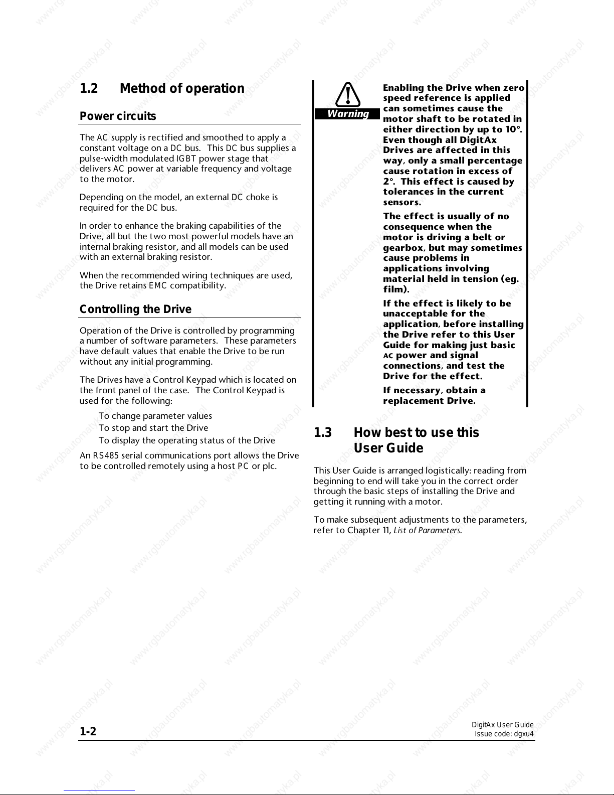
Warning
Enabling the Drive when zero
speed reference is applied
can sometimes cause the
motor shaft to be rotated in
either direction by up to 10°°.
Even though all DigitAx
Drives are affected in this
way, only a small percentage
cause rotation in excess of
2°°. This effect is caused by
tolerances in the current
sensors.
The effect is usually of no
consequence when the
motor is driving a belt or
gearbox, but may sometimes
cause problems in
applications involving
material held in tension (eg.
film).
If the effect is likely to be
unacceptable for the
application, before installing
the Drive refer to this User
Guide for making just basic
AC power and signal
connections, and test the
Drive for the effect.
If necessary, obtain a
replacement Drive.
1.3 How best to use this
User Guide
This User Guide is arranged logistically: reading from
beginning to end will take you in the correct order
through the basic steps of installing the Drive and
getting it running with a motor.
To make subsequent adjustments to the parameters,
refer to Chapter 11, List of Parameters.

DigitAx User Guide
Issue code: dgxu4
Safety information 2-1
2 Safety Information
2.1
Warnings, Cautions
and Notes
A Warning contains information which is essential
for avoiding a safety hazard.
A Caution contains information which is necessary
for avoiding a risk of damage to the product or
other equipment.
A Note contains information which helps to ensure
correct operation of the product.
2.2 Electrical safety –
general warning
The voltages used in the Drive can cause severe
electric shock and/or burns, and could be lethal.
Extreme care is necessary at all times when working
with or adjacent to the Drive.
Specific warnings are given at the relevant places in
this User Guide and the accompanying User Guide.
The installation must comply with all relevant safety
legislation in the country of use.
2.3 System design
The Drive is intended as a component for
professional incorporation into complete equipment
or systems. If installed incorrectly the Drive may
present a safety hazard. The Drive uses high
voltages and currents, carries a high level of stored
electrical energy, and is used to control mechanical
equipment which can cause injury.
Close attention is required to the electrical
installation and the system-design to avoid hazards
either in normal operation or in the event of
equipment malfunction. System-design,
installation, commissioning and maintenance must
be carried out by personnel who have the necessary
training and experience. They must read this safety
information and User Guide carefully.
To ensure mechanical safety, additional safety
devices such as electro-mechanical interlocks may
be required. The Drive must not be used in a safety-
critical application without additional high-integrity
protection against hazards arising from a
malfunction.
2.4 Environmental limits
Instructions in this User Guide regarding transport,
storage, installation and use of Drives must be
complied with, including the specified
environmental limits. Drives must not be subjected
to excessive physical force.
2.5 Compliance with
regulations
The installer is responsible for complying with all
relevant regulations, such as national wiring
regulations, accident prevention regulations and
electromagnetic compatibility (EMC) regulations.
Particular attention must be given to the
cross-sectional areas of conductors, the selection of
fuses or other protection, and protective earth
(ground) connections.
This User Guide contains instructions for achieving
compliance with specific EMC standards.
Within the European Union, all machinery in which
this product is used must comply with the following
directives:
98/37/EC: Safety of Machinery
89/336/EEC: Electromagnetic Compatibility.
2.6 Safety of personnel
The STOP function of the Drive does not remove
dangerous voltages from the output of the Drive or
from any external option unit.
The Stop and Start controls or electrical inputs of
the Drive should not be relied upon to ensure safety
of personnel. If a safety hazard could exist from
unexpected starting of the Drive, an interlock that
electrically isolates the Drive from the
AC supply
must be installed to prevent the motor being
inadvertently started.
Careful consideration must be given to the
functions of the Drive which might result in a hazard
through incorrect operation due to a fault or trip
(eg. stop/start, forward/reverse, maximum speed).
Under certain conditions, the Drive can suddenly
discontinue control of the motor. If the load on the
motor could cause the motor speed to be increased
(eg. hoists and cranes), a separate method of
braking and stopping the motor must be used (eg. a
mechanical brake).
DigitAx User Guide
Issue code: dgxu4
2-2 Safety information
Before connecting the AC supply to the Drive, it is
important that you understand the operating
controls and their operation. If in doubt, do not
adjust the Drive. Damage may occur, or lives put at
risk. Carefully follow the instructions in this User
Guide.
Before making adjustments to the Drive, ensure all
personnel in the area are warned. Make notes of all
adjustments that are made.
2.7 Risk analysis
In any application where a malfunction of the Drive
could lead to damage, loss or injury, a risk analysis
must be carried out, and where necessary, further
measures taken to reduce the risk. This would
normally be an appropriate form of independent
safety back-up system using simple electro-
mechanical components.
2.8 Motor
Ensure the motor is installed in accordance with the
manufacturer’s recommendations. Ensure the
motor shaft is not exposed.
2.9 Adjusting parameters
Some parameters have a profound effect on the
operation of the Drive and protection of the motor.
They must not be altered without careful
consideration of the impact on the controlled
system. Measures must be taken to prevent
unwanted changes due to error or tampering.
DigitAx User Guide
Issue code: dgxu4
3-1
3 Data
Warning
The voltages present in the
Drive are capable of
inflicting a severe electric
shock and may be lethal. The
Stop function of the Drive
does not remove dangerous
voltages from the Drive or
the driven machine.
AC supplies to the Drive
must be disconnected at
least 15 minutes before any
cover is removed or
servicing work is performed.
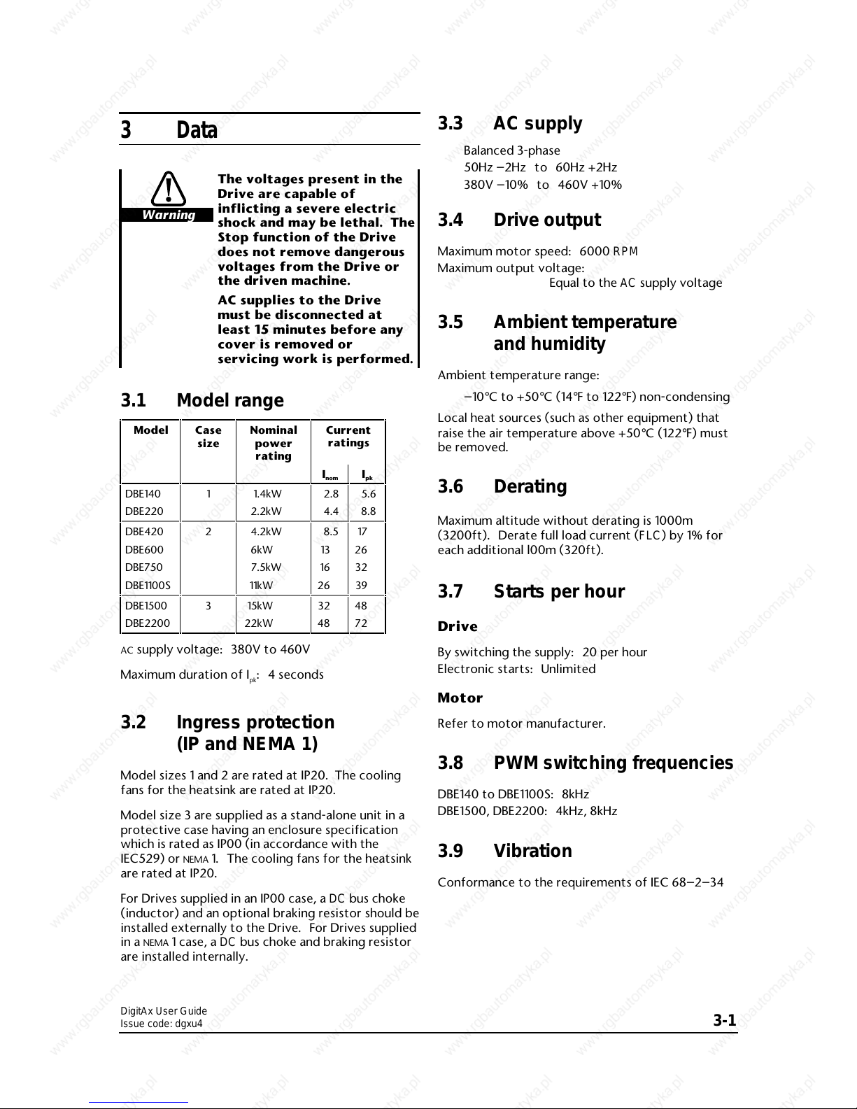
3.1 Model range
Model Case
size
Nominal
power
rating
Current
ratings
I
nomIpk
DBE140
DBE220
1 1.4kW
2.2kW
2.8
4.4
5.6
8.8
DBE420
DBE600
DBE750
DBE1100S
2 4.2kW
6kW
7.5kW
11kW
8.5
13
16
26
17
26
32
39
DBE1500
DBE2200
3 15kW
22kW
324848
72
AC supply voltage: 380V to 460V
Maximum duration of I
pk
: 4 seconds
3.2 Ingress protection
(IP and NEMA 1)
Model sizes 1 and 2 are rated at IP20. The cooling
fans for the heatsink are rated at IP20.
Model size 3 are supplied as a stand-alone unit in a
protective case having an enclosure specification
which is rated as IP00 (in accordance with the
IEC529) or
NEMA 1. The cooling fans for the heatsink
are rated at IP20.
For Drives supplied in an IP00 case, a DC bus choke
(inductor) and an optional braking resistor should be
installed externally to the Drive. For Drives supplied
in a
NEMA 1 case, a DC bus choke and braking resistor
are installed internally.
3.3 AC supply
Balanced 3-phase
50Hz –2Hz to 60Hz +2Hz
380V –10% to 460V +10%
3.4 Drive output
Maximum motor speed: 6000 RPM
Maximum output voltage:
Equal to the AC supply voltage
3.5 Ambient temperature
and humidity
Ambient temperature range:
–10°C to +50°C (14°F to 122°F) non-condensing
Local heat sources (such as other equipment) that
raise the air temperature above +50°C (122°F) must
be removed.
3.6 Derating
Maximum altitude without derating is 1000m
(3200ft). Derate full load current (FLC) by 1% for
each additional l00m (320ft).
3.7 Starts per hour
Drive
By switching the supply: 20 per hour
Electronic starts: Unlimited
Motor
Refer to motor manufacturer.
3.8 PWM switching frequencies
DBE140 to DBE1100S: 8kHz
DBE1500, DBE2200: 4kHz, 8kHz
3.9 Vibration
Conformance to the requirements of IEC 68–2–34
DigitAx User Guide
Issue code: dgxu4
3-2
3.10 Serial communications
RS485 half-duplex (RS422 can also be used)
Protocol: ANSI x 3.28–2.5–A4–N, positive logic
Timing
Write to Drive:
25ms at 9600 Baud
l5ms at 19.2 kBaud
Read from the Drive:
30ms at 9600 Baud
16ms at 19.2 kBaud
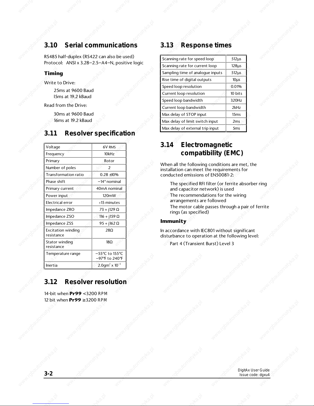
3.11 Resolver specification
Voltage 6V RMS
Frequency 10kHz
Primary Rotor
Number of poles 2
Transformation ratio 0.28 ±10%
Phase shift –14° nominal
Primary current 40mA nominal
Power input 120mW
Electrical error ±15 minutes
Impedance ZRO 73 + j129 Ω
Impedance ZSO 116 + j159 Ω
Impedance ZSS 95 + j162 Ω
Excitation winding
resistance
28Ω
Stator winding
resistance
18Ω
Temperature range –55°C to 155°C
–97°F to 240°F
Inertia 2.0gm2 x 10
–5
3.12 Resolver resolution
14-bit when Pr99 < 3200 RPM
12 bit when Pr99 ≥ 3200 RPM
3.13 Response times
Scanning rate for speed loop 512µs
Scanning rate for current loop 128µs
Sampling time of analogue inputs 512µs
Rise time of digital outputs 10µs
Speed loop resolution 0.01%
Current loop resolution 10 bits
Speed loop bandwidth 320Hz
Current loop bandwidth 2kHz
Max delay of STOP input 15ms
Max delay of limit switch input 2ms
Max delay of external trip input 5ms
3.14 Electromagnetic
compatibility (EMC)
When all the following conditions are met, the
installation can meet the requirements for
conducted emissions of EN50081-2:
The specified RFI filter (or ferrite absorber ring
and capacitor network) is used
The recommendations for the wiring
arrangements are followed
The motor cable passes through a pair of ferrite
rings (as specified)
Immunity
In accordance with IEC801 without significant
disturbance to operation at the following level:
Part 4 (Transient Burst) Level 3
DigitAx User Guide
Issue code: dgxu4
3-3
3.15 Frequency accuracy
Output frequency is within 100ppm of the
demanded frequency.
3.16 Weights
The weights of the most powerful model in each
model size are as follows:
Model size 1: 5.5kg (12lb)
Model size 2: 9.5kg (21lb)
Model size 3: 22.3kg (49lb)
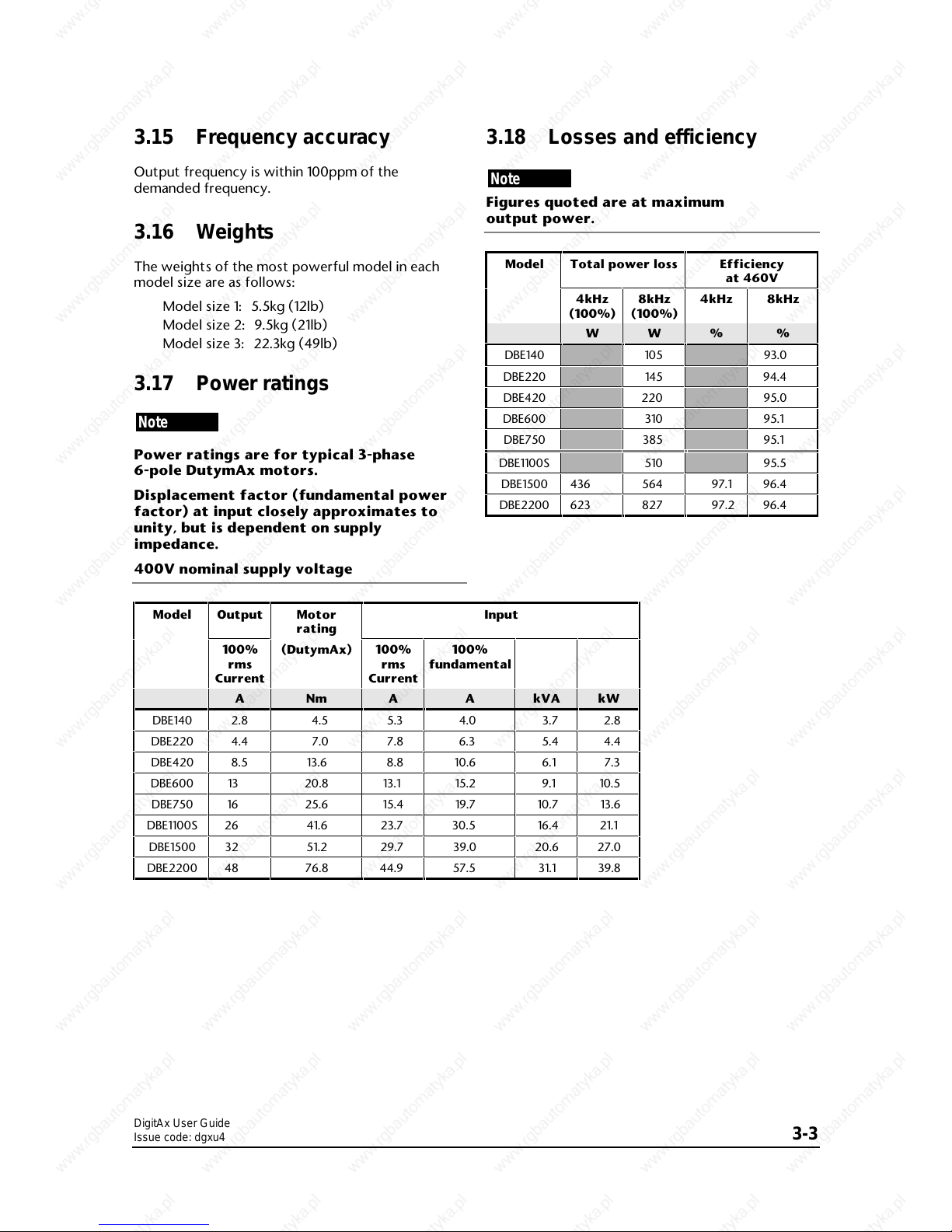
3.17 Power ratings
Note
Power ratings are for typical 3-phase
6-pole DutymAx motors.
Displacement factor (fundamental power
factor) at input closely approximates to
unity, but is dependent on supply
impedance.
400V nominal supply voltage
3.18 Losses and efficiency
Note
Figures quoted are at maximum
output power.
Model Total power loss Efficiency
at 460V
4kHz
(100%)
8kHz
(100%)
4kHz 8kHz
W
W
% %
DBE140
105
93.0
DBE220
145
94.4
DBE420
220
95.0
DBE600
310
95.1
DBE750
385
95.1
DBE1100S
510
95.5
DBE1500 436
564
97.1 96.4
DBE2200 623
827
97.2 96.4
Model Output Motor
rating
Input
100%
rms
Current
(DutymAx) 100%
rms
Current
100%
fundamental
A Nm A A kVA kW
DBE140 2.8 4.5 5.3 4.0 3.7 2.8
DBE220 4.4 7.0 7.8 6.3 5.4 4.4
DBE420 8.5 13.6 8.8 10.6 6.1 7.3
DBE600 13 20.8 13.1 15.2 9.1 10.5
DBE750 16 25.6 15.4 19.7 10.7 13.6
DBE1100S 26 41.6 23.7 30.5 16.4 21.1
DBE1500 32 51.2 29.7 39.0 20.6 27.0
DBE2200 48 76.8 44.9 57.5 31.1 39.8
DigitAx User Guide
Issue code: dgxu4
3-4
3.19 DC bus choke ratings
DC bus chokes are fitted internally on the DBE420 to
DBE1100S drives. No DC bus choke is needed for
models DBE140 and DBE220.
Ripple frequency = 6 × supply frequency
Ratings and values quoted are design minima.
Drive
model
Choke ratings Weight
mH ARMS Apk kg lb
DBE1500 1.50 45 85 6.4 14
DBE2200 0.70 75 143 8.4 19
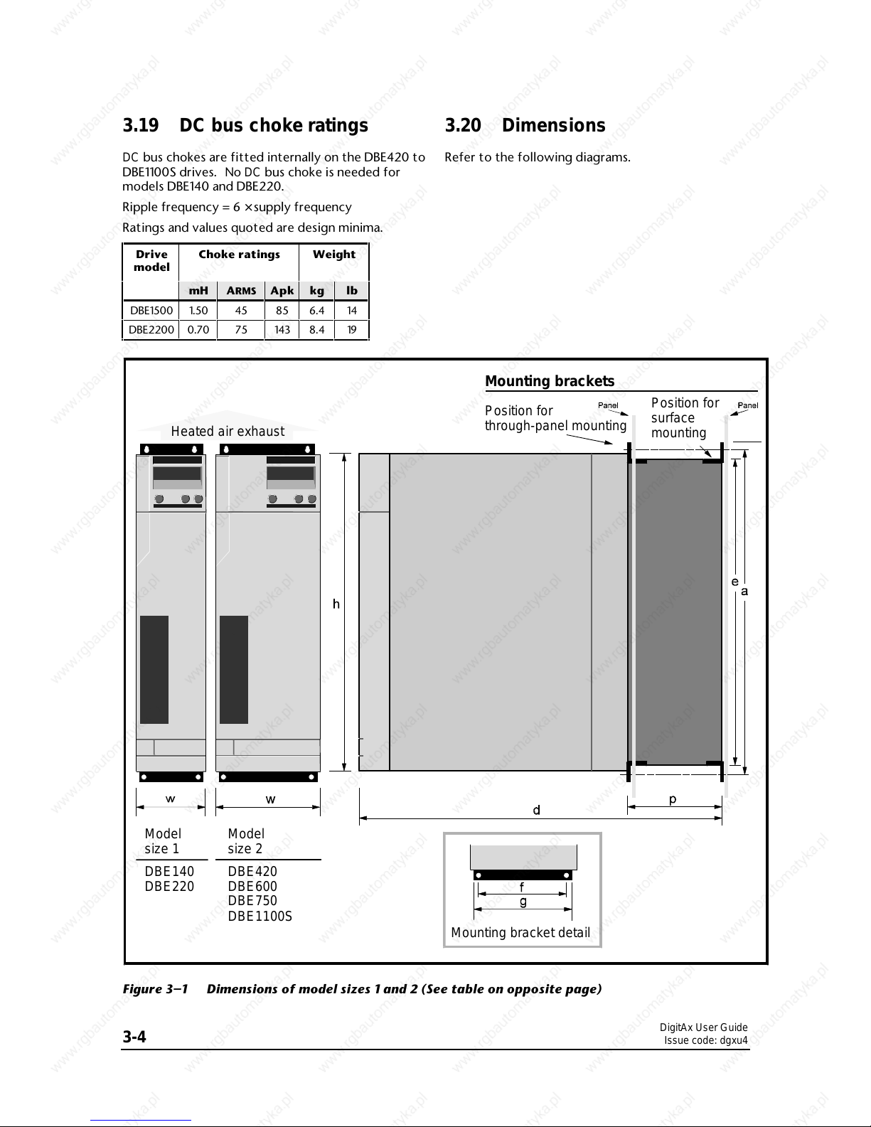
3.20 Dimensions
Refer to the following diagrams.
Heated air exhaust
Mounting brackets
Position for
through-panel mounting
Position for
surface
mounting
Model
size 1
DBE140
DBE220
Model
size 2
DBE420
DBE600
DBE750
DBE1100S
Mounting bracket detail
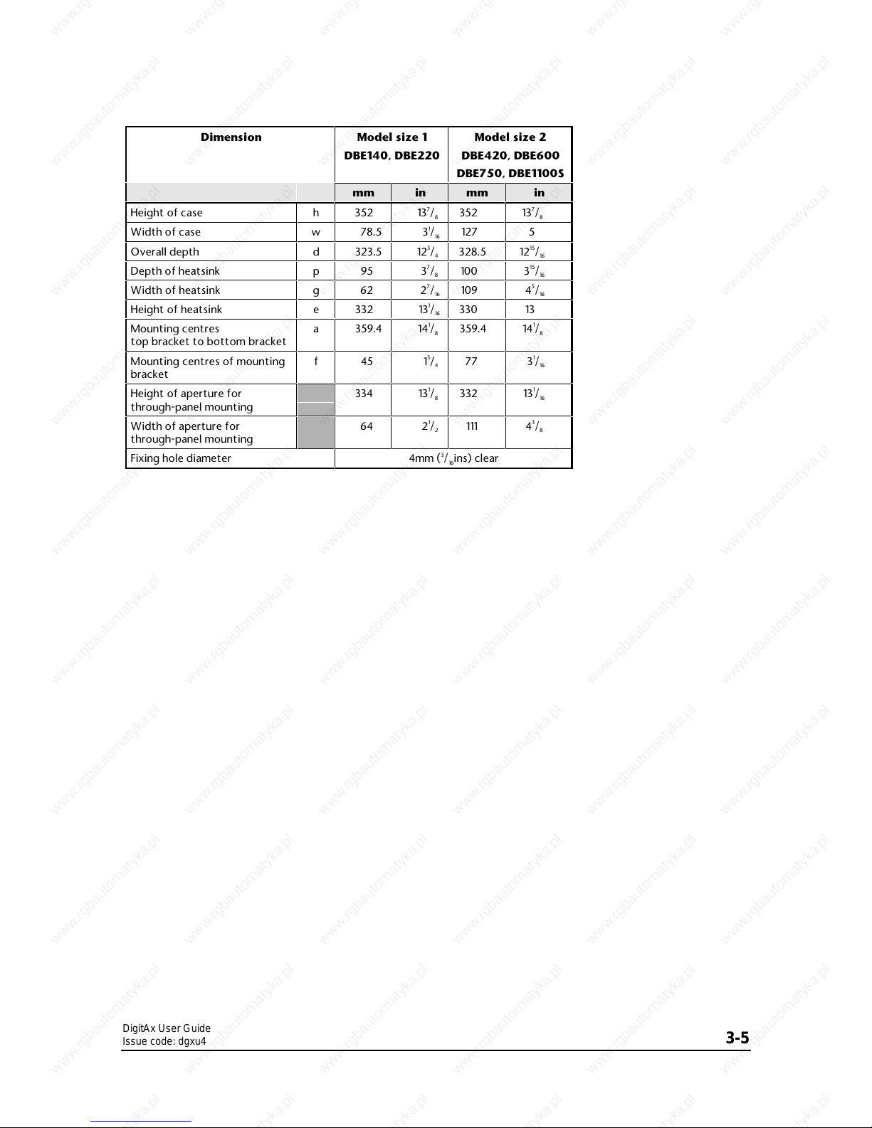
Figure 3–1 Dimensions of model sizes 1 and 2 (See table on opposite page)
DigitAx User Guide
Issue code: dgxu4
3-5
Dimension Model size 1
DBE140, DBE220
Model size 2
DBE420, DBE600
DBE750, DBE1100S
mm in mm in
Height of case h 352 137/8352 137/
8
Width of case w 78.5 31/16127 5
Overall depth d 323.5 123/4328.5 1215/
16
Depth of heatsink p 95 37/8100 315/
16
Width of heatsink g 62 27/16109 45/
16
Height of heatsink e 332 131/16330 13
Mounting centres
top bracket to bottom bracket
a 359.4 141/8359.4 141/
8
Mounting centres of mounting
bracket
f45 1
3
/477 31/
16
Height of aperture for
through-panel mounting
334 131/8332 131/
16
Width of aperture for
through-panel mounting
64 21/
2
111 43/
8
Fixing hole diameter 4mm (3/16ins) clear
DigitAx User Guide
Issue code: dgxu4
3-6
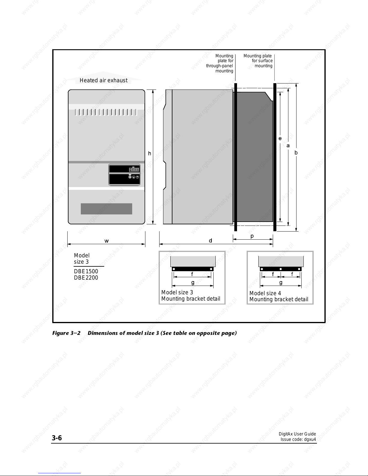
Heated air exhaust
Model
size 3
DBE1500
DBE2200
Mounting
plate for
through-panel
mounting
Mounting plate
for surface
mounting
Model size 3
Mounting bracket detail
Model size 4
Mounting bracket detail
Figure 3–2 Dimensions of model size 3 (See table on opposite page)
DigitAx User Guide
Issue code: dgxu4
3-7
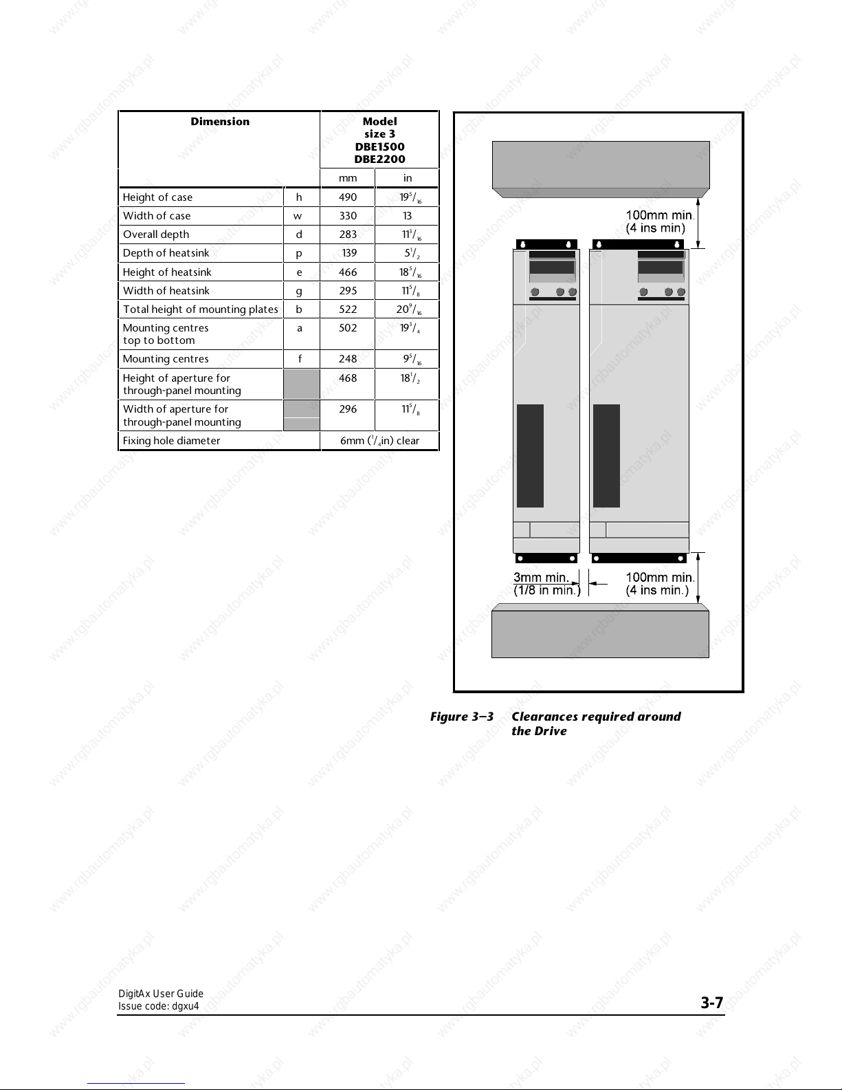
Figure 3–3 Clearances required around
the Drive
Dimension Model
size 3
DBE1500
DBE2200
mm in
Height of case h 490 195/
16
Width of case w 330 13
Overall depth d 283 113/
16
Depth of heatsink p 139 51/
2
Height of heatsink e 466 185/
16
Width of heatsink g 295 115/
8
Total height of mounting plates b 522 209/
16
Mounting centres
top to bottom
a 502 193/
4
Mounting centres f 248 95/
16
Height of aperture for
through-panel mounting
468 181/
2
Width of aperture for
through-panel mounting
296 115/
8
Fixing hole diameter 6mm (1/4in) clear

DigitAx User Guide
Issue code: dgxu4
3-8
DigitAx User Guide
Issue code: dgxu4
4-1
4 Mechanical Installation
Warning
The equipment enclosure is
rated at IP20 in accordance
with IEC539. It is designed
for installation within a
protective enclosure which
prevents unauthorised
access except for trained
service personnel, and
prevents contamination with
conductive dust and
condensation.
4.1 EMC wiring
recommendations
To minimize radio-frequency emissions, it is
necessary to install the Drive in a steel enclosure and
pay attention to the arrangement of the wiring
inside the enclosure. Figure 4–1 shows
recommendations for the layout of the enclosure.
Figures 5–1 and 5–3 in Chapter 5 Electrical Installation
show examples of wiring arrangements for minimum
radio-frequency emissions. The actual arrangement
will have to be adapted to individual requirements.
When planning the installation, refer to Chapter 5 in
addition to this chapter.
The essential requirements are as follows:
RFI filter
• Mount an RFI filter above the Drive at a
distance of 125mm (5 in).
• Make the AC power cables from the RFI
filter to the Drive as short as possible.
• Use a flat conductor at least 10mm (
1
/2in)
wide and as short as possible to make the
ground connection from the RFI filter to the
Drive.
Motor cable
• Use armoured or shielded cable to connect
the motor to the Drive. Connect the
armour or shield to the Drive and to the
motor frame. Make these connections no
longer than 50mm (2in).
• If the length of cable used to connect the
motor to the Drive exceeds 50m (150 feet),
output chokes may be required in order to
prevent cable capacitance effects causing
over-current trips (OC) in the Drive. For
difficult cases, consult the supplier of the
Drive.
Resolver wiring
Simulated-encoder wiring
• Signal connections from the resolver and
from the simulated encoder input of the
CNC controller must be connected to the
Drive using cable consisting of three
twisted-pairs of wire. Each twisted pair
must be screened, and the cable must have
an overall screen. Connect the screens of
the resolver cable only to terminal B18 of the
Drive. Connect the screens of the simulated
encoder output only to the CNC controller
ground terminal.
• When a motor thermistor is to be used,
connect it to the Drive using a fourth
twisted-pair in the screened cable to the
resolver. Connect the screen for this
twisted-pair only to terminal B18 on the
Drive.
Analog speed reference wiring
• Use shielded twisted-pair cable to connect
the analog speed reference to the Drive. It
is strongly recommended that a true
differential signal source is used in order to
maximize immunity to electrical noise.
Connect the cable shield only to the ground
connection of the CNC controller.
• A single-ended signal source may be used,
but electrical noise immunity is reduced.
Use shielded twisted-pair cable. Apply the
signal to terminal B9 or B10 of the Drive, as
required. Connect the 0V common to
terminal B11. Connect the unused
differential input (terminal B10 or B9) to
terminal B11.
Ground connections
• Bus-bars must be used to make certain
ground connections, as shown in Figure 5–4.
These bus-bars must be made of copper bar
of the dimensions shown.
Ferrite absorber ring
• When a number of Drives are installed in an
enclosure, it is recommended that a ferrite
absorber ring is fitted over the AC supply
cables to each Drive. (See also Capacitor
network.)
• Part numbec: 4200-3608
Capacitor network
• When three or more Drives are installed in
an enclosure, a capacitor network may be
required. Refer to Figure 5–4.
DigitAx User Guide
Issue code: dgxu4
4-2
4.2 Planning the installation
The following conditions must be met when
planning the installation of the Drive or a number of
Drives in an enclosure:
• The environment is acceptable
• The maximum permissible ambient
temperature is not exceeded
• The EMC requirements are met
• The electrical installation meets safety
requirements
• The size of the installation does not
exceed the space available
Use the following procedure:
1. Decide how the Drives are to be mounted in the
enclosure, as follows:
• Surface-mounted
• Through-panel mounted
Surface mounting gives the following:
Better ingress protection
Heat dissipated inside the enclosure
Through-panel mounting gives the following:
Heat dissipated outside the enclosure
Reduced ingress protection
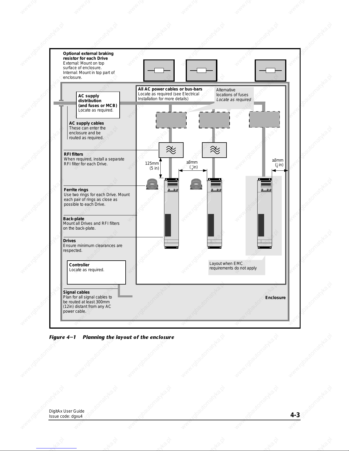
2. Refer to Figure 4–1 to plan the layout of the
equipment in the enclosure.
3. If the Drives are to be surface mounted in the
enclosure, refer to either of the following:
If the enclosure is to be sealed, perform the
calculations in Heat dissipation in a sealed
enclosure in order to determine the minimum
permissible size of enclosure for heat
dissipation.
If the enclosure is to be ventilated, perform the
calculation in Heat dissipation in a ventilated
enclosure in order to determine the required
volume of air-flow.
4. If necessary, adjust the size of the enclosure,
and re-plan the internal equipment accordingly.
Repeat instructions 2 to 4 as many times as
required to meet all the requirements.
DigitAx User Guide
Issue code: dgxu4
4-3
≥3mm
( in)
Optional external braking
resistor for each Drive
External: Mount on top
surface of enclosure.
Internal: Mount in top part of
enclosure.
Controller
Locate as required.
Signal cables
Plan for all signal cables to
be routed at least 300mm
(12in) distant from any AC
power cable.
Drives
Ensure minimum clearances are
respected.
RFI filters
When required, install a separate
RFI filter for each Drive.
AC supply cables
These can enter the
enclosure and be
routed as required.
AC supply
distribution
(and fuses or MCB)
Locate as required.
All AC power cables or bus-bars
Locate as required (see Electrical
Installation for more details)
Enclosure
Layout when EMC
requirements do not apply
Alternative
locations of fuses
Locate as required
125mm
(5 in)
Back-plate
Mount all Drives and RFI filters
on the back-plate.
≥3mm
( in)
Ferrite rings
Use two rings for each Drive. Mount
each pair of rings as close as
possible to each Drive.
Figure 4–1 Planning the layout of the enclosure
DigitAx User Guide
Issue code: dgxu4
4-4
4.3 Environment
1. In accordance with the IP20 rating of the Drive,
the Drive must be located in an environment
that is free from dust, corrosive vapours, gases
and all liquids, including condensation of
atmospheric moisture.
2. If condensation is likely to occur when the Drive
is not in use, install an anti-condensation heater.
This heater must be switched off when the
Drive is in use; automatic switching is
recommended.
3. Do not locate the Drive in a classified hazardous
area, unless the Drive is installed in an approved
enclosure and the installation is approved.
4. Install the Drive vertically for best flow of
cooling air.
5. Install the Drive as low as possible in the
enclosure without contravening EMC
requirements.
6. Observe the requirements for ambient
temperature if the Drive is to be mounted
directly above any heat generating equipment,
such as another Drive.
7. If the Drive is to be installed directly beneath
other equipment, such as another Drive, ensure
the Drive does not cause the ambient
temperature requirements of the equipment to
be exceeded.
8. Allow at least 100mm (4in) clearance above and
below the Drive.
9. Allow at least 3mm (
1
/8in) clearance each side of
the Drive.
4.4 RFI filters
Install the RFI filter specified for the Drive model as
follows. Use one RFI filter for each Drive. (Ferrite
absorber rings and a capacitor network can be used
in place of an RFI filter. See Ferrite absorber rings
below.)
Drive model
Filter part
number
DBE140
4200–4810
DBE420
4200–4810
DBE420
4200–4810
DBE600
4200–4820
DBE750
4200–4820
DBE1100S
4200–4830
DBE1500
4200–1051
DBE2200
4200–1051
Filter
part
number
Filter dimensions
Length Width Depth
4200–
mm in
mm
in mm in
4810 250 915/
16
110
43/860 23/
8
4820 270 103/
4
140
59/
16
60 23/
8
4830 270 103/
4
140
59/
16
60 23/
8
1051 330 13
190
75/8145 511/
16
4.5 Ferrite absorber ring
A ferrite absorber ring and capacitor network may
be used in place of an RFI filter for all models, except
for models DBE1500 and DBE2200. See Figure 5–4.
DigitAx User Guide
Issue code: dgxu4
4-5
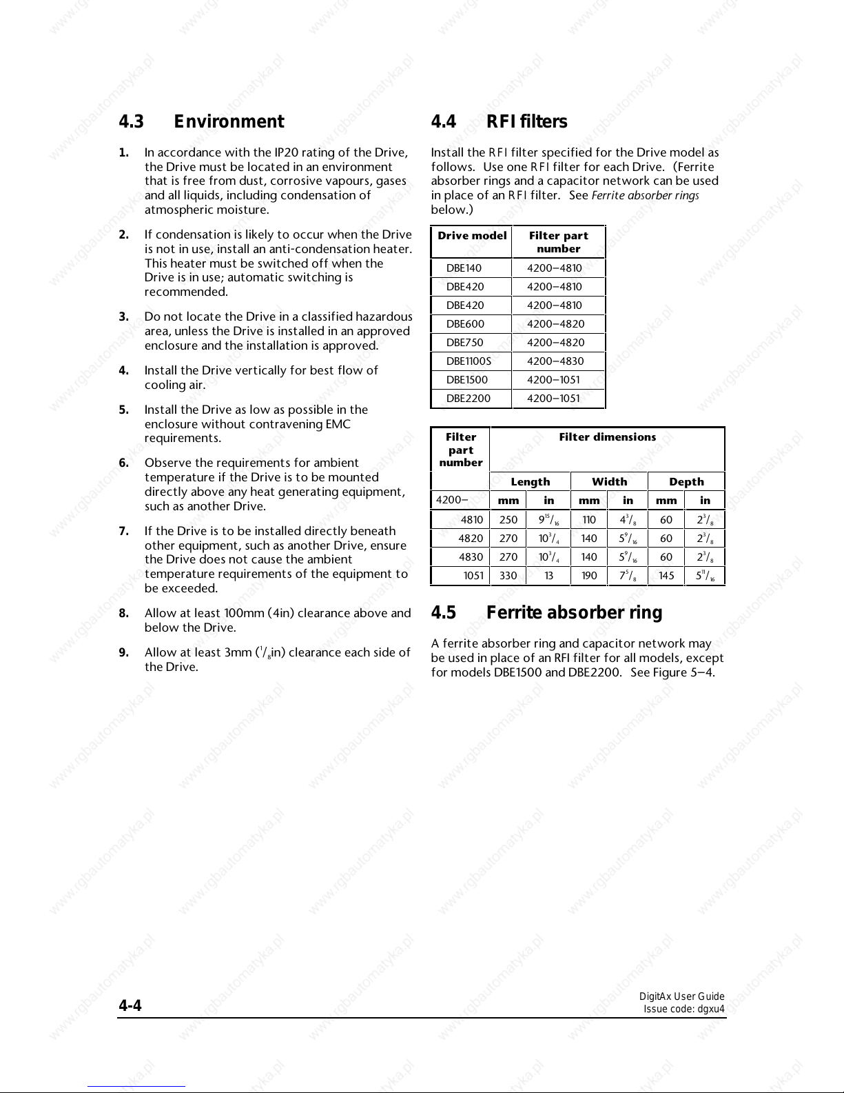
4.6 Ferrite rings
The three conductors of the motor cable from each
Drive must pass twice through two ferrite rings, as
shown in Figures 5–2 and 5–3.
Part number: 4200-0000
Dimension mm in
A 105 43/
16
B241
C622
1
/
2
D 28.5 11/
8
E903
5
/
8
Mounting hole diameter 5
3
/
16
Figure 4–2 Dimensions of the ferrite rings
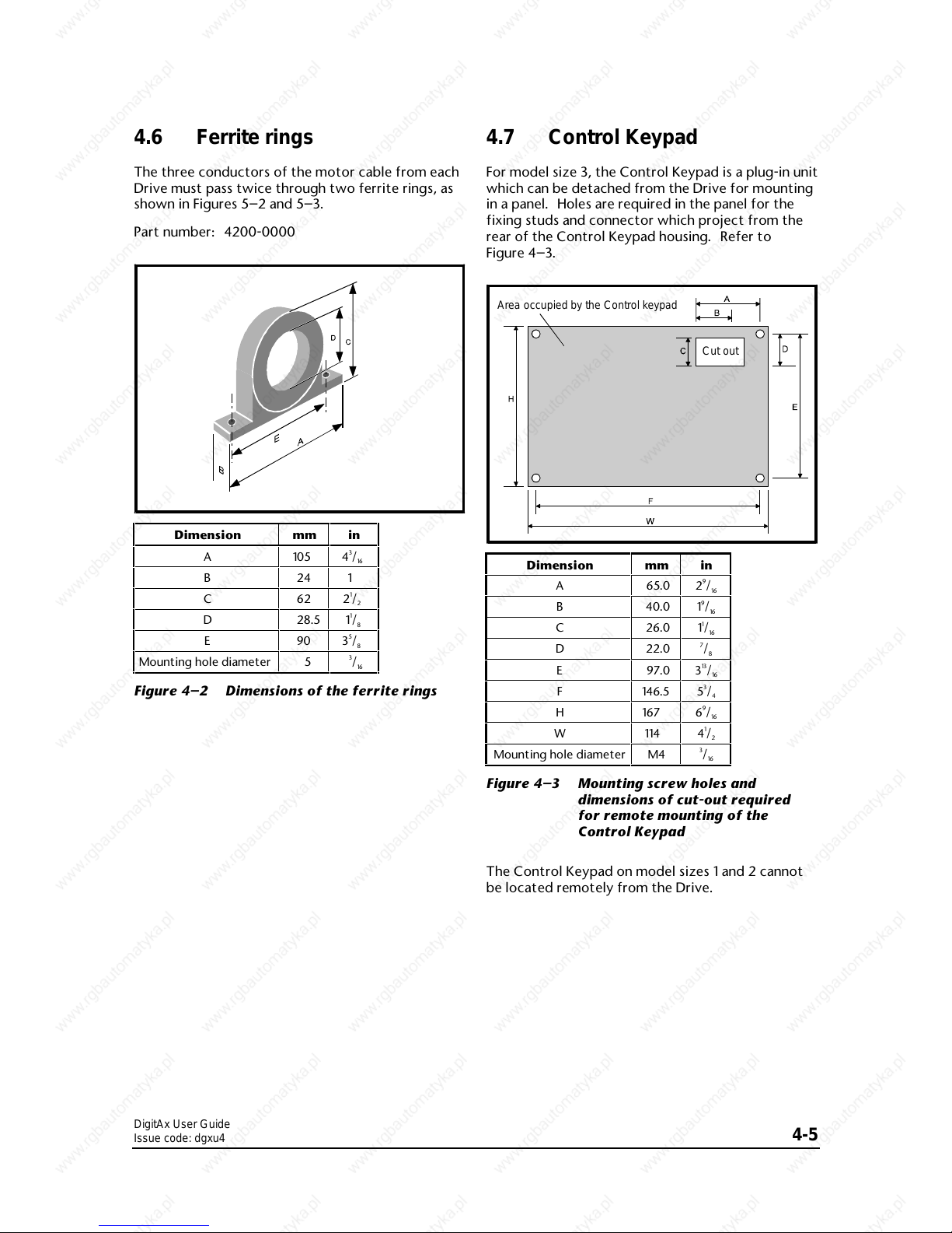
4.7 Control Keypad
For model size 3, the Control Keypad is a plug-in unit
which can be detached from the Drive for mounting
in a panel. Holes are required in the panel for the
fixing studs and connector which project from the
rear of the Control Keypad housing. Refer to
Figure 4–3.
Area occupied by the Control keypad
Cut out
Dimension
mm
in
A
65.0
29/
16
B
40.0
19/
16
C
26.0
11/
16
D
22.0
7
/
8
E
97.0
313/
16
F
146.5
53/
4
H
167
69/
16
W
114
41/
2
Mounting hole diameter
M4
3
/
16
Figure 4–3 Mounting screw holes and
dimensions of cut-out required
for remote mounting of the
Control Keypad
The Control Keypad on model sizes 1 and 2 cannot
be located remotely from the Drive.

DigitAx User Guide
Issue code: dgxu4
4-6
4.8 Installing an external DC
braking resistor
When an external braking resistor is to be installed,
it should be installed in accordance with the
manufacturer’s instructions. Refer to Calculating the
braking resistor value in Chapter 5 Electrical Installation.
4.9 Installing a DC bus choke
For model size 3, an external DC bus choke is
required. The choke may be mounted in the same
enclosure as the Drive.
No external DC bus choke is required for model
sizes 1 and 2.
Note
Drives supplied in NEMA 1 case contain the
required DC bus choke.
A
A
A
A
A
A
A
A
A
A
A
A
A
A
A
A
A
A
A
A
A
A
A
A
A
A
A
A
A
A
A
A
A
A
A
A
A
A
A
A
A
A
A
A
A
A
A
A
A
A
A
A
A
A
A
A
A
A
A
A
A
A
A
A
A
A
A
A
A
A
A
A
A
A
A
A
A
A
A
A
A
A
A
A
A
A
A
A
A
A
A
A
A
A
A
A
A
A
A
A
A
A
A
A
A
A
A
A
A
A
A
A
A
A
A
A
A
A
A
A
A
A
A
A
A
A
A
A
A
A
A
A
A
A
A
A
A
A
A
A
A
A
A
A
A
A
A
A
A
A
A
A
A
A
A
A
A
A
A
A
A
A
A
A
A
A
A
A
A
A
A
A
A
A
A
A
A
A
A
A
A
A
A
A
A
A
A
A
A
A
A
A
A
A
A
A
A
A
A
A
A
A
A
A
A
A
A
A
A
A
A
A
A
A
A
A
A
A
A
A
A
A
A
A
A
A
A
A
A
A
A
A
A
A
A
A
A
A
A
A
A
A
A
A
A
A
A
A
A
A
A
A
A
A
A
A
A
A
A
A
A
A
A
A
A
A
A
A
A
A
A
A
A
A
A
A
A
A
A
A
A
A
A
A
A
A
A
A
A
A
A
A
A
A
A
A
A
A
A
A
A
A
A
A
A
A
A
A
A
A
A
A
A
A
A
A
A
A
A
A
A
A
A
A
A
A
A
A
A
A
A
A
A
A
A
A
A
A
A
A
A
A
A
A
A
A
A
A
A
A
A
A
A
A
A
A
A
A
A
A
A
A
A
A
A
A
A
A
A
A
A
A
A
A
A
A
A
A
A
A
A
A
A
A
A
A
A
A
A
A
A
A
A
A
A
A
A
A
A
A
A
A
A
A
A
A
A
A
A
A
A
A
A
A
A
A
A
A
A
A
A
A
A
A
A
A
A
A
A
A
A
A
A
A
A
A
A
A
A
A
A
A
A
A
A
A
A
A
A
A
A
A
A
A
A
A
A
A
A
A
A
A
A
A
A
A
A
A
A
A
A
A
A
A
A
A
A
A
A
A
A
A
A
A
A
A
A
A
A
A
A
A
A
A
A
A
A
A
A
A
A
A
A
A
A
A
A
A
A
A
A
A
A
A
A
A
A
A
A
A
A
A
A
A
A
A
A
A
A
A
A
A
A
A
A
A
A
A
A
A
A
A
A
A
A
A
A
A
A
A
A
A
A
A
A
A
A
A
A
A
A
A
A
A
A
A
A
A
A
A
A
A
A
A
A
A
A
A
A
A
A
A
A
A
A
A
A
A
A
A
A
A
A
A
A
A
A
A
A
A
A
A
A
A
A
A
A
A
A
A
A
A
A
A
A
A
A
A
A
A
A
A
A
A
A
A
A
A
A
A
A
A
A
A
A
A
A
A
A
A
A
A
A
A
A
A
A
A
A
A
A
A
A
A
A
A
A
A
A
A
A
A
A
A
A
A
A
A
A
A
A
A
A
A
A
A
A
A
A
A
A
A
A
A
A
A
A
A
A
A
A
A
A
A
A
A
A
A
A
A
A
A
A
A
A
A
A
A
A
A
A
A
A
A
A
A
A
A
A
A
A
A
A
A
A
A
A
A
A
A
A
A
A
A
A
A
A
A
A
A
A
A
A
A
A
A
A
A
A
A
A
A
A
A
A
A
A
A
A
A
A
A
A
A
A
A
A
A
A
A
A
A
A
A
A
A
A
A
A
A
A
A
A
A
A
A
A
A
A
A
A
A
A
A
A
A
A
A
A
A
A
A
A
A
A
A
A
A
A
A
A
A
A
A
A
A
A
A
A
A
A
A
A
A
A
A
A
A
A
A
A
A
A
A
A
A
A
A
A
A
A
A
A
A
A
A
A
A
A
A
A
A
A
A
A
A
A
A
A
A
A
A
A
A
A
A
A
A
A
A
A
A
A
A
A
A
A
A
A
A
A
A
A
A
A
A
A
A
A
A
A
A
A
A
A
A
A
A
A
A
A
A
A
A
A
A
A
A
A
A
A
A
A
A
A
A
A
A
A
A
A
A
A
A
A
A
A
A
A
A
A
A
A
A
A
A
A
A
A
A
A
A
A
A
A
A
A
A
A
A
A
A
A
A
Value A B C D E Terminal
size
mH mminmminmminmminmm
in
1.50 137
5
7
/
16
84
3
5
/
16
175
6
7
/
8
24
15
/
16
10
3
/
8
M8
0.70 137
5
7
/
16
116
4
9
/
16
175
6
7
/
8
24
15
/
16
10
3
/
8
M8
Figure 4–4 Dimensions of the DC bus choke
4.10 Heat dissipation in a
sealed enclosure
To maintain sufficient cooling of the Drive when it is
installed inside a sealed enclosure, heat generated
by all the equipment in the enclosure must be taken
into account and the enclosure must be of adequate
size. To calculate the minimum acceptable size of
enclosure, use the following procedure.
Calculate the minimum required surface area A
e
for
the enclosure from:
(())
A
P
kT T
e
iamb
==
−−
where:
A
ee
= Unobstructed heat-conducting area in m
2
k = Heat Transmission coefficient of the
enclosure material in Watts/m
2
/°C
T
i
= Maximum permissible operating
temperature in °C of the Drive
T
amb
= Maximum external ambient
temperature in °C
P = Power in Watts dissipated by all heat
sources in the enclosure
Example
To calculate the size of an enclosure for one
DBE2200 Drive. The following conditions are
assumed:
The installation is to conform to IP54, requiring
the Drive to be surface-mounted within a
sealed enclosure
Only the top, front and two sides of the
enclosure are free to dissipate heat
The enclosure is constructed of painted
2mm (
3
/32 inch) sheet steel
Maximum external ambient temperature:
25°C (77°F)
Drive PWM switching frequency: 8kHz
DigitAx User Guide
Issue code: dgxu4
4-7
Insert the following values:
P = 827W (from Losses and Efficiency
table)
T
i
= 50°C (122°F)
T
amb
= 25°C (77°F)
k = 5.5 (typical value for painted 2mm
(
1
/16 inch) sheet steel)
The minimum required heat conducting area is then:
(())
Am
e
==
−−
==
827
5 5 50 25
60
2
.
.
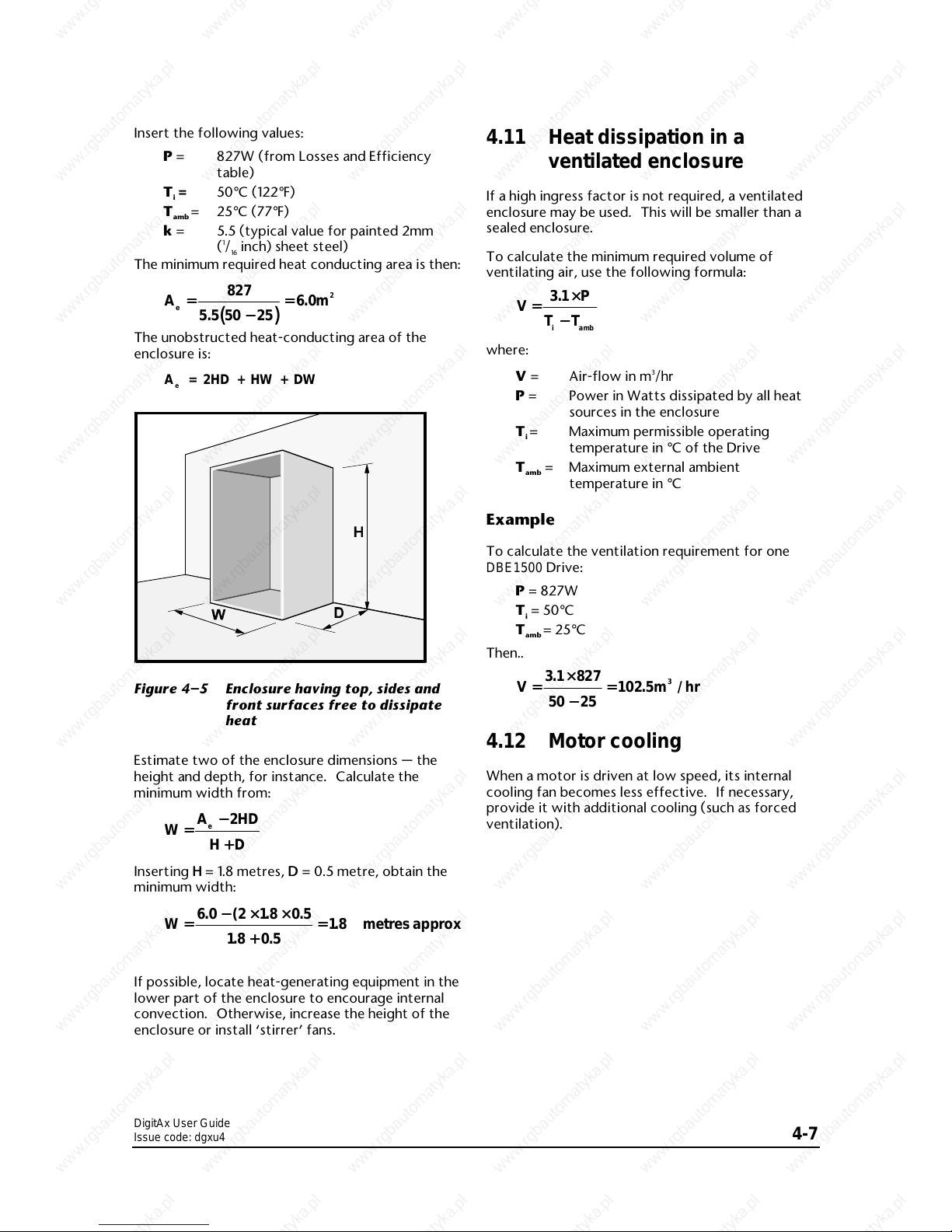
The unobstructed heat-conducting area of the
enclosure is:
A = 2HD + HW + DW
e
Figure 4–5 Enclosure having top, sides and
front surfaces free to dissipate
heat
Estimate two of the enclosure dimensions — the
height and depth, for instance. Calculate the
minimum width from:
W
AHD
HD
e
==
−−++2
Inserting HH = 1.8 metres, D D = 0.5 metre, obtain the
minimum width:
W metresapprox==
−−××××
++
==
60 2 18 05
18 0 5
18
.( . .
..
.
If possible, locate heat-generating equipment in the
lower part of the enclosure to encourage internal
convection. Otherwise, increase the height of the
enclosure or install ‘stirrer’ fans.
4.11 Heat dissipation in a
ventilated enclosure
If a high ingress factor is not required, a ventilated
enclosure may be used. This will be smaller than a
sealed enclosure.
To calculate the minimum required volume of
ventilating air, use the following formula:
V
P
TT
iamb
==
××
−−
31.
where:
V = Air-flow in m3/hr
P = Power in Watts dissipated by all heat
sources in the enclosure
T
i
= Maximum permissible operating
temperature in °C of the Drive
T
amb
= Maximum external ambient
temperature in °C
Example
To calculate the ventilation requirement for one
DBE1500 Drive:
P = 827W
T
i
= 50°C
T
amb
= 25°C
Then..
V m hr==
××
−−
==
3 1 827
50 25
102 5
3
.
. /
4.12 Motor cooling
When a motor is driven at low speed, its internal
cooling fan becomes less effective. If necessary,
provide it with additional cooling (such as forced
ventilation).

DigitAx User Guide
Issue code: dgxu4
4-8
DigitAx User Guide
Issue code: dgxu4
5-1
5 Electrical Installation
Warning
The voltages present in the
Drive are capable of
inflicting a severe electric
shock and may be lethal. The
Stop function of the Drive
does not remove dangerous
voltages from the Drive or
the driven machine. AC
supplies to the Drive must
be disconnected using an
approved isolation device
before any cover is removed
or service work is
performed.
Warning
Electric shock risk
If the Drive has been
energized, the supply must
be isolated for at least
fifteen minutes. This allows
the internal capacitors to
discharge fully before work
may continue. Refer to
Safety information on the
inside front cover of this
user guide.
5.1 Hazardous areas
Approval and certification for hazardous areas
should be obtained for the complete installation of
the motor and Drive.
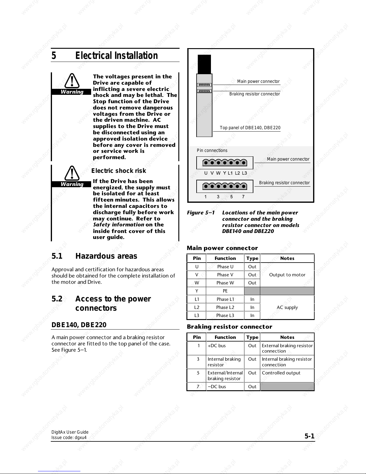
5.2 Access to the power
connectors
DBE140, DBE220
A main power connector and a braking resistor
connector are fitted to the top panel of the case.
See Figure 5–1.
Main power connector
Braking resistor connector
Top panel of DBE140, DBE220
Main power connector
Braking resistor connector
Pin connections
Figure 5–1 Locations of the main power
connector and the braking
resistor connector on models
DBE140 and DBE220
Main power connector
Pin Function
Type
Notes
U Phase U
Out
V Phase V
Out
Output to motor
W Phase W
Out
YPE
L1 Phase L1
In
L2 Phase L2
In
AC supply
L3 Phase L3
In
Braking resistor connector
Pin Function
Type
Notes
1 +DC bus
Out
External braking resistor
connection
3 Internal braking
resistor
Out
Internal braking resistor
connection
5 External/Internal
braking resistor
Out
Controlled output
7 –DC bus
Out
 Loading...