

Digitana VCS3 MKII Quad Midi-CV User Manual
VCS3(mk2) QUAD MIDI
-
CV INTERFACE
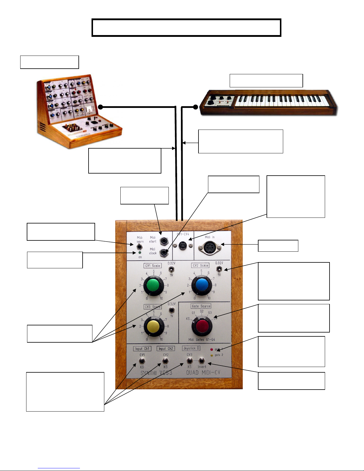
LED
VCS3(mk2)
Cable to rear of
VCS3 with 8 pin Male
plug
Midi Start
Stop output
DK1/2 Keyboard
Cable to rear of the
Dk1 or DK2 Keyboard
with 8 pin female plug
Midi clock
output
Socket for
special 4-way
EMS matrix pin
cable carrying
CV1-CV4
Midi Learn Switch
Normally OFF
Midi activity
CV1-CV3 Scaling
Potentiometers
Toggle switches to
switch between
keyboard (KS or DK)
control or Midi-CV
control
VCS3 (mk2) QUAD MIDI-CV
MIDI INPUT
Toggle switches for
changing the range
of CV1-CV3 to
maximum of either
0.32V/Oct or 1V/Oct
Gate trigger Source
KS or DK Keyboard
G1-G4 are midi gates
1-4
Gate LEDs. These
light when gate1 or
gate2 are triggered
by MIDI
Inverts CV3 voltage
+ve -> -ve

Instructions on using the VCS3(mk2) Quad Midi-CV Interface
This is a Quad Midi-CV unit designed to be used with an EMS VCS3(mk2), either with or
without an EMS Dk1/2 keyboard or an EMS external Touch Keyboard Sequencer (KS). It is
based around Marc Bareille’s fantastic 3-channel micro-controller based Midi-CV converter
called the ‘MCV876’ (which Marc has kindly allowed me to incorporate in the modules)
See details of Marc’s unit and all its many features at his website:-
http://m.bareille.free.fr/mcv876/mcv876.html
The latest units I ship have the most recent firmware (v3.06 as of October 2010) for the
Pic18F2320 microcontroller which has faster better performance than the older models
(based on Pic16F876 microcontrollers).
Before Power On
With the VCS3 powered off, plug in the two grey cables with the 8 way ‘Jones’ plugs at each
end. The male Jones plug to the rear of the VCS3 ‘keyboard’ socket, and the female to the
DK1/2 keyboard (if you have one). The Quad Midi CV unit allows independent switching
between a connected DK/KS keyboard and midi control, through front panel toggle
switches. Switch on the VCS3. You will see the green midi activity led (top left) flash a few
times to indicate all is well.
The midi-cv board in the Quad Midi is powered by tapping off the +12V/-9V from the VCS3
(via the Jones plug cables) but only a small current is drawn so that normal operation of the
VCS3(mk2) is unaffected.
PLEASE NOTE FOR A VCS3 (mk1) YOU SHOULD USE THE SPECIALLY DESIGNED QUAD MIDI
CV UNIT made for the mk1 and its weaker internal psu.
N.B. The toggle switch at top left IS NOT A POWER ON/OFF SWITCH! It is the Midi learn
switch (discussed below) and it should always be kept in the off (up) position in normal use.
The Quad Midi-CV unit has no on/off power switch. It is powered on/off when the VCS3 is
switched on/off.
The Midi Activity Led (green)
This is a multi-purpose led! The led blinks a few times at power on. Then the led will
monitor all incoming recognised MIDI status bytes. The led also blink 3 long blinks if the
interface receives the "Write To Flash" sysex message. When this message is received, all
MCV876 parameters are written into the flash RAM. So the MCV876 can recall a setup even
after a power off. When the interface is in MIDI Learn mode, the led stays on, until a MIDI
message has been received and learned by the interface. In ‘mono’ play mode (see play
modes description below) the mid activity led flashes when midi notes are received. In other
play modes it remains off when midi notes are sent..this is simply to speed up the mid->cv
conversion in polyphonic and multi play modes where every bit of processing speed is
‘squeezed’ out of the microcontroller.
•
Multi2
•
•
•
•
The "MIDI learn" switch
To place the unit in midi learn mode toggle the midi learn switch on then off (down and back
up). The midi activity led stays on until a MIDI message has been received and learned by the
interface. The led will blink 3 long blinks if the interface receives the "Write To Flash" sysex
message and will then automatically go out of midi learn mode to midi play mode.
If you wish to come out of midi learn mode without sending any new configuration data just
toggle the midi learn switch down and up once more. Then the led will switch off and the
unit is in the standard play mode.
NB: the normal position for the midi learn toggle switch is in the ‘up’ position.
Here is how Midi learn works:
When you toggle the Midi Learn switch down then back up the midi activity led stays on
and the MCV876 is in Learn Mode waiting to receive a Midi message containing Midi
channel information. When a message arrives ( you play a note on the master keyboard for
example) , the Midi channel number is extracted, compared to the actual interface Midi
channel and set to this new value if different. If the Midi channel of the message is identical
to the one configured into the interface, and if the message received is a Midi note ON
message, the interface extracts the Midi number of the note played and sets this value as
the reference (base or lowest ) note. This allows transpose of the MCV876 to any note on
the keyboard. The reference note is the Lowest note the interface can play ( digital zero).
Using the small Windows configuration programme available from Marc’s website you can
configure the unit to any of the available play modes mode as you desire.
V3.06 Firmware and different Play Modes
The Quad Midi-CV unit can be configured in these different playmodes using the windows
configuration programme (version 3) which is available from
http://m.bareille.free.fr/mcv876/mcv876.html
CV1-Gate1 assigned to Note On/Off messages
• CV2, CV3,CV4* are assignable to controllers, velocity or PitchBend..
Mono
• Gates 2,3,4 are assignable to controllers.
• One channel recognition
CV1/Gate1 and CV2/Gate2 are on channel N - CV1 assignable to MIDI notes
• CV3/Gate3 and CV/Gate4 are on channel N+1 - CV4* assignable to MIDI notes
CV1 to CV4*and Gate1 to 4 are respectively on channels N to N+4
Multi4
Poly2
Poly4
*note CV4 is only available on the Quad Midi-CV units.
• CVs or gates can be assigned to MIDI notes or controllers independently.
CV1 +Gate1 and CV2+Gate2 are assigned to Note On/Off messages
• CV3 and CV4* are assignable to controllers, velocity or PitchBend..
CV1 to CV4* and Gate1 to 4 are assigned to Note On/Off message
Triggering the VCS3 Envelope Shaper
The unit has Envelope Shaper (ES) trigger assignable to either keyboard (DK1 or DK2 if
present) or any of the 4 gates (gate1-gate4) via a front panel rotary switch. How many of the
4 gates are available depends on the mode used (see above). Eg in Poly2 mode, only 2 gates
are available (gate1 and gate2). In poly 4 mode or Controller mode, all 4 gates are available
to trigger the ES.
Red and yellow panel LED’s light when midi Gate 1 and/or Gate2 are triggered.
Gate 5 and gate 6 outputs are via jack sockets and offer Midi start/Stop and Midi clock
signals for interfacing and synchronizing with other external midi devices.
Using the front panel CV Scaling Potentiometers
CV1-CV3 can be scaled using the 3 front panel potentiometer knobs. These allow different
response to midi generated control voltages. Of particular importance is the fact that EMS
Synthi oscillators use 0.32V/Octave standard NOT 1V/Octave as on most other synths. For
pitch CV1 it is necessary to switch the toggle switch to the 0.32V/Oct setting and scale knob
set to maximum value 10. This will produce correct chromatic scales on Osc1 and Osc2. For
CV2 and CV3 you can either use 0.32V or 1V/Oct setting as you wish for different responses.
The 1V/Oct option is useful if a CV channel is being used as a modulation source rather than
give pitch control of a synthi Oscillator. Also if your Synthi oscillators 1 and/or 2 are not
exactly scaled to 0.32V/Oct.. use the 1V setting and adjust the scaling pots until you get
proper chromatic pitches.
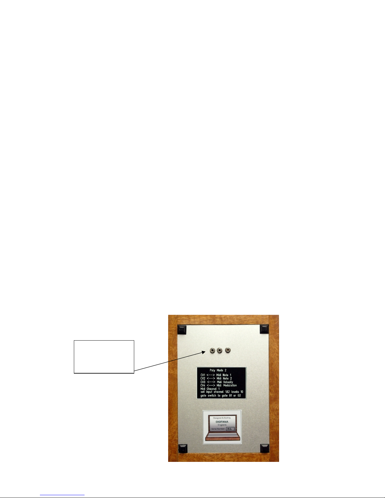
NEW FEATURE FOR 2010: precision multi-turn trimmers for fine tuning of
0.32V/Oct scaling of CV1-CV3.
On the rear of all Midi-CV units produced form Nov 2010 onwards, you will find 3 multi-turn
trimmers. These are adjusted by inserting a small flat head screwdriver.
CV1, CV2 and CV3
0.32V/Oct fine tune
trimmers
 Loading...