

Page 1

SNAP2410/2414/2420
Spread Spectrum
Network Access Points
Installation Guide
April 20, 2000
One Meca Way
Norcro ss, Geo rgia 30093
www.digital-wireless.com
(770) 564-55 40
Page 2

Note: This unit has been tested and found to comply
with the limits for a class A digital device, pursuant to
part 15 of the FCC Rules. These limits are designed to
provide reasonable protection against harmful
interference when the equipment is operated in a
commercial environment. This equipment generates,
uses, and can radiate radio frequency energy and, if not
installed and used in accordance with the instruction
manual, may cause harmful interference to radio
communications. Operation of this equipment in a
residential area is likely to cause harmful interference
in which case the user will be required to correct the
interference at his own expense. Commensurate with
EIRP limits specified in FCC Rules 15.247b, this
device may not be used with antennas that exceed
36dB of gain i n poi nt-to-poi nt applications or 16dB of
gain in multi-point applications.
Transmitter Module FCCID: HSW-2410M.
Page 3

Table of Contents
Introduction...................................................................................................... 1
Getting Started................................................................................................. 2
Connecting the SNAP.................................................................................... 2
SNAP Status Indicators................................................................................. 3
Configuring the SNAP.................................................................................... 3
SNAP Operation............................................................................................... 5
Overview....................................................................................................... 5
TCP/IP Addresses......................................................................................... 5
Seamless Roaming........................................................................................ 6
Synchronization............................................................................................. 7
AP Mode Operation....................................................................................... 7
PPP Operation .............................................................................................. 8
4-Port Hub..................................................................................................... 8
SNAP Command Set........................................................................................ 9
SNAP System Commands............................................................................. 9
Ethernet Commands.....................................................................................10
SNAP Radio Commands...............................................................................11
AP Mode Commands....................................................................................12
PPP Mode Commands .................................................................................13
Radio Modem Configuration ............................................................................15
Radio Commands.........................................................................................15
SNAP Datagram Protocol (SDP)......................................................................17
Overview......................................................................................................17
SDP Header.................................................................................................17
SDP Messages.............................................................................................18
Troubleshooting ..............................................................................................21
Technical Support.........................................................................................21
Quick Reference..............................................................................................22
Specifications..................................................................................................25
Warranty.........................................................................................................26
Page 4

INTRODUCTION
The SNAP2410 family of products from Digital Wireless Corporation provides Ethernet
connectivity to networks of WIT2410 radios. Built around the WIT2410, SNAP products
provide a 10BaseT connection to Ethernet networks and function as base stations for
remote devices containing WIT2410 transceivers. By supporting seamless roaming,
multiple SNAPs can be connected to a network to provide practically unlimited coverage
area. To simplify system installation some SNAPs have built-in 4-port hubs with an
uplink port. In addition, these SNAPs allow for power to be distributed through the hub
ports.
Depending on the model, SNAPs have one or two WIT2410 transceivers. Each radio can
support 62 simultaneous remotes. Thus SNAPs can support up to 124 simultaneous
remotes. Each remote radio has a unique ID number, so the number of remotes that can
communicate with a SNAP is unlimited, subject to a limit of 62 remotes at any one time.
The communication between the SNAP and the WIT2410 remotes is performed using the
WIT2410 over-the-air protocol. Thus the SNAP products are 802.3 compatible but not
802.11 compatible. By using the 460Kbps over-the-air data rate the WIT2410 protocol,
the full range of WIT2410 radios is realized, three times the range of most 802.11
products.
The SNAPs enjoy the same benefits of frequency-hopping spread spectrum technology
that the WIT2410s do. Namely, the immunity to multipath fading and resistance to
jamming that is provided by changing frequency every few milliseconds. Operating in the
2.4GHz ISM band, SNAPs can be used license-free worldwide and are not subject to the
congestion in the 900MHz band caused by cordless telephones.
The SNAP has two modes of operation, AP and PPP. The default mode is the AP mode.
In this mode the SNAP uses a special protocol mode called SDP(
Protocol)
. In order to send receive or transmit data from the SNAP, the application
SNAP Datagram
software must use this protocol. The user may use the API roam library included with
the SNAP to help shorten software development.
The SNAP can also be configured as a PPP server. This allows any computer with a
remote to connect to the same network as the SNAP. These computers then could access
any files on the network and support browser-based applications.
2000 Digital Wireless Corporation 1 042000
Page 5
GETTING STARTED
The SNAP family of wireless Ethernet modems are easy to install and operate. In most
instances, the only installation steps will be setting IP addresses, selecting one modem as
the master and connecting the antenna, power and Ethernet cable.
Connecting the SNAP
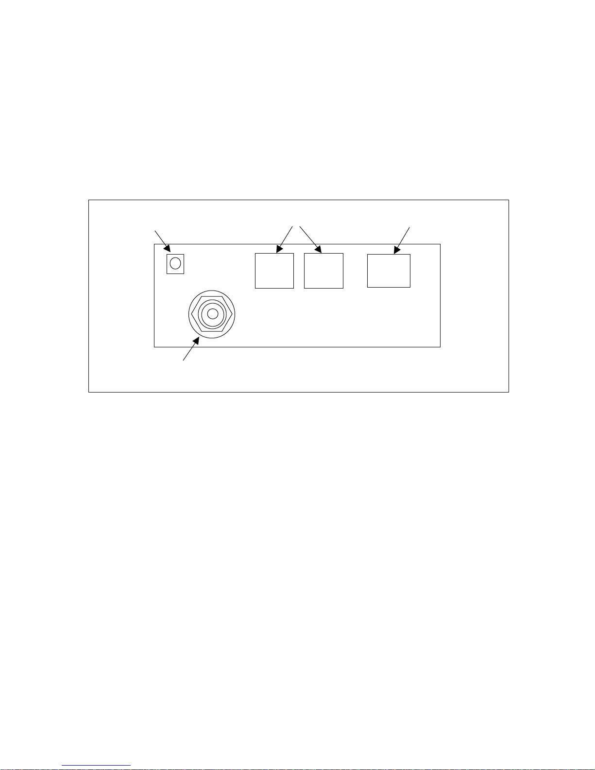
Figure 1 identifies the various connectors on the rear of the SNAP2410.
Power Connector
TNC Antenna Connector
Synchronizing Signals 10BaseT Ether net Connector
Figure 1. SNAP Rear Panel Diagram
The antenna connector is a TNC type connector. An antenna may be connected directly
to this connector. Alternatively, an antenna may be located away from the SNAP using
RF cable to connect the SNAP to the antenna. Digital Wireless does not recommend
using RF cables longer than 5 feet. If more distance is required between the SNAP and
the antenna, high-quality, low-loss RF feed line must be used.
The 10BaseT Ethernet connector is the standard RJ-45 connector. The connector is wired
to be able to connect directly to an Ethernet hub using a straight-through cable. If it is
desired to connect the SNAP directly to a PC without a hub, the SNAP must be
connected with a cross-over cable.
The synchronizing signals are provided for special applications where multiple master
SNAPs are employed in an environment with slave SNAPs that are moving. The
synchronizing signals are RS-485 levels and may be connected using an RJ-11 connector.
In most instances the synchronizing signals are not required and may be left unconnected.
The power connector is a 2-pin DIN type connector. The provided AC adapter provides a
9 volt power level to the SNAP. The SNAP can accept DC voltages ranging between
7VDC and 26VDC if alternative power supplies are to be used.
2000 Digital Wireless Corporation 2 042000
Page 6
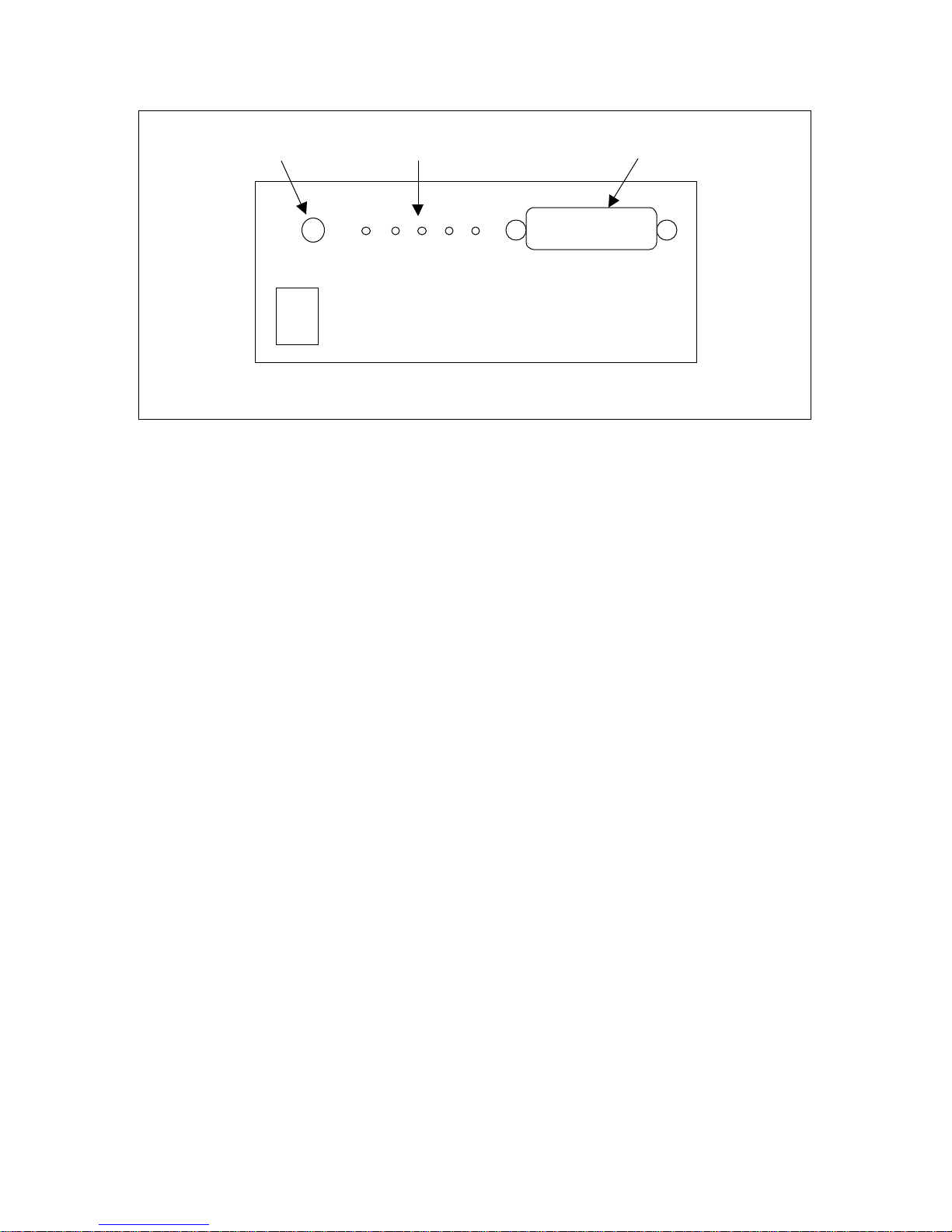
Power Switch Status Indicators
Conf iguratio n Por t
SNAP 2410
2.4 GHz SPREAD SPECTRUM WIRELESS ETHERNET MODEM
Figure 2. SNAP2410 Front Panel Diagram
The Configuration Port is an RS-232 serial port that may be used to configure the SNAP.
This is useful when the default IP address of the SNAP cannot be used with the existing
network preventing configuration through a telnet session. See the section Configuring
the SNAP for details of using this port.
SNAP Status Indicators
The PWR indicator on the front panel indicates that power is applied to the SNAP and
that the power switch is in the ON position.
TXD and RXD are indicators of data activity. They indicate the transmission and
reception of data over the Ethernet connection. Note that these LEDs can be active even
when the SNAP has no remote radios registered.
The COLL indicator is illuminated whenever packets collide on the network segment to
which the SEM is connected. As such, this is rough indicator of the level of traffic on the
network segment. If this LED is glowing brightly on a continuous basis, the throughput
of the SEM may appear to be reduced.
The LINK indicator when illuminated indicates a good connection to the Ethernet
network. If this LED is not on, it can indicate a cross-wired connection between the
SNAP and the network. It may also indicate a faulty cable connection.
Configuring the SNAP
SNAPs are shipped from the factory with default settings that include a default IP address
of 192.168.0.254. The network that the SNAP is connecting to must be compatible with
10BaseT products. The SNAP
will not
work if the network only supports 100BaseT
products. Before connecting a default configured SNAP to an active network, ask the
network system administrator to make sure that the default IP number will not cause any
2000 Digital Wireless Corporation 3 042000
Page 7

problems on the network and that the SNAP will be recognized by the network. If the
default IP address conflicts with a device on the existing network, the SNAP will need to
be configured through the serial port.
The SNAP can be configured two ways. The first is through the serial port. The settings
for the serial port are 38400 baud, 8 data bits, 1 stop bit, and no parity. WinSNAP will
automatically find the appropriate serial port and configure the serial port settings for
you. The software will inform you of its progress and any problems that arise. After a
few seconds the SNAP firmware version is displayed followed by the
SNAP>
prompt.
The second configuration method is through a telnet session. Most telnet programs work
with the SNAP. Windows 95/98/NT/2000 have a telnet program that works with the
SNAP. If there are no conflicts with the default IP number, initiate a telnet session to the
SNAP. A telnet session can be started by clicking on Start->Run if you have Windows
95/98/NT/2000 and the TCP/IP client has been installed. Enter the following information
in the dialog box:
telnet 192.168.0.254
A telnet window will open up. The first line is the version of the SNAP firmware
followed by the prompt:
SNAP>
To change the IP number of the SNAP, use the ip command.
ip <xxx.xxx.xxx.xxx> {yyy.yyy.yyy.yyy}
Where x is the new IP address, and y is the optional netmask number.
Store the changed configuration parameters in non-volatile memory with the save
command:
save<CR>
The SNAP will report back the time it took to the save the information. Reset the SNAP
by typing:
reset<CR>
The SNAP can also be reset by cycling power. Whenever a reset is executed on the
SNAP, the telnet session will be lost. It will take the SNAP about 30 seconds to
reinitialize after a reset or after cycling power.
Note: The save and reset commands must be entered aft er modi f ying t he
default configuration. Failure to do so will result in the factory defaults to
be used.
2000 Digital Wireless Corporation 4 042000
Page 8

SNAP OPERATION
Overview
At the most basic level, SNAPs can be thought of as Ethernet-to-serial interface adapt ers .
That is, they take data from a host application over a 10BaseT Ethernet connection,
remove the Ethernet header information, format the data for WIT2410 radios and
transmit the data to the on-board WIT2410 through a high-speed serial interface. In the
other data flow direction, the on-board WIT2410 receives data from a remote WIT2410
device. The SNAP takes this data and provides the necessary Ethernet datagram
encapsulation and transmits the datagram to the host application over the connected
network.
A SNAP can be used standalone, or a group of SNAPs can be connected together through
a 10BaseT hub to provide seamless roaming over a larger area. When seamless roaming
operation is desired, the SNAPs must be synchronized with each other. This
synchronization is accomplished either over the Ethernet network or through a
differential Sync signal when time delay devices (such as routers) are between SNAPs.
See the section on Synchronization for details.
Communication between the host application SNAPs can occur at one of two levels.
Provided with the SNAP is a library of C routines that constitute a high level API for
workstation-based applications. Alternatively, host applications can communicate with a
SNAP using the SNAP Datagram Protocol (SDP). This protocol is described in detail
later in this manual.
The SNAP has a serial Configuration port in addition to the 10BaseT port. This port
allows configuration of the SNAP without having to connect it to a network. The
WinSNAP configuration utility provided with the SNAP is used to configure the SNAP
through the serial Configuration port. Any configuration of the SNAP can be performed
using either the Configuration port or over the network.
TCP/IP Addresses
Each SNAP must be configured with a unique IP address that is appropriate for the
network where the SNAP will be used. The IP address can be set using the ip command
through the serial-port interface. The ip command takes one or two parameters. The first
parameter specifies the IP address for the SNAP, and the second optional parameter, if
present, specifies the netmask for the SNAP. If the second parameter is not used, the
netmask is set to the default netmask for the IP address specified. For example, the
command:
ip 192.168.0.1
will set the SNAP’s IP address to 192.168.0.1 and the netmask will remain
255.255.255.0.
2000 Digital Wireless Corporation 5 042000
Page 9

The command:
ip 192.168.1.233 255.255.255.192
will set the SNAP’s IP address to 192.168.1.233 and will change the netmask to
255.255.255.192. The ip command without any parameters will display the current
setting of the IP address and netmask. The SNAP includes a simple ping command that
can be used to test the IP address and routing table settings.
The SNAP can also obtain its IP address from a BOOTP server if one is present in the
network. The BOOTP server will require the Ethernet hardware MAC address to be able
to assign the IP address to the SNAP. The Ethernet hardwate MAC address of the SNAP
is configured as 00:30:66:XX:YY:ZZ, where XX:YY:ZZ is the unique ID of the SNAP’s
“radio A”.
The route command can be used to modify and display the IP routing table entries. To
display the routing table, use the route list command. There will always be one entry in
the routing table that corresponds to the IP address of the SNAP. For most applications,
if any routing table entries are required, it will be sufficient to set a default route. To set
the default route, use the command:
route add default <gwaddr>
where <gwaddr> is the IP address of the default gateway (usually a router or routing
host). To remove the default route, use the command “route del default”. To add a route
to a particular network or host, use the command “route add <dest> <gw> [<netmask>]”,
where “<dest>” is the destination network or host IP address, “<gw>” is the IP address of
the gateway, and the optional “<netmask>” is the netmask which defines the destination
network.
Seamless Roami ng
The SNAP2410 allows remote radios to seamlessly roam between multiple SNAP2410.
The remote radios can also be configured not to roam if this is the required operating
condition. In order for the remote to be able to roam seamless the <wg> parameter must
be set to 2. When the RSSI (receive signal strength indictor) of the remote reaches a
certain threshold, the remote will start looking for another SNAP with a higher RSSI.
The SNAP will be notified with a CONNECT and DISCONNECT packet when a remote
leaves or connects with a SNAP.
To facilitate seamless roaming among a group of SNAPs, the SNAPs use Ethernet
packets to synchronize time relative to each other. A single “master” SNAP will
broadcast (or multicast) special UDP datagrams to the “slave” SNAPs to deliver timing
information through the network. The SNAPs can also synchronize with one another by
RJ-11 cable (telephone cable). The RJ-11 method of synchronization uses a daisy chain
fashion to connect the SNAPs together. The SNAPs need to be synchronized this way if
2000 Digital Wireless Corporation 6 042000
Page 10

the ethernet packets can not be transmitted in a timely manner, such as going through a
router.
Synchronization
The SNAP uses broadcast or multicast datagrams for time synchronization. The default
is for the master SNAP to broadcast datagrams to the 255.255.255.255 all-hosts IP
broadcast address. Using the “sys xcast <ipaddr>”, SNAPs can be configured to use a
more limited IP broadcast address, or a multicast address. All SNAPs in a network
should be configured with the same “xcast” address. The use of multicast addresses is
preferred so that synchronization datagrams do not interfere with hosts other than the
SNAPs. Note that the SNAPs use UDP port 2410 as the source and destination UDP port
numbers in the synchronization packets.
The command “sync master” is used to set a SNAP to the master for time
synchronization, and the command “sync slave” is used to set a SNAP to be a slave for
time synchronization. There should be one master in a given network, even if there is
only one SNAP in the network.
There may be a time when there will be SNAP on different sides of a network router.
This situation could cause the SNAPs not to be synchronized. This is where the RJ-11
sync connectors can be used. If the remotes will need to be able to roam between the
SNAP located on different sides of the network router, the SNAP will have to be
connected together using the RJ-11 connectors. The cable will only need to be two
twisted pair. This is the same as regular phone cable. If there are more than two SNAPs
in the network, the SNAPs will need to be daisy chained together.
AP Mode Operation
The default operating mode of the SNAP is AP mode. This mode is optimized for
communications between a workstation or workstations on an Ethernet network and a
network of WIT2410-based devices. The AP mode assumes that there is limited
intelligence in the remote host. The AP mode is designed to allow the remote host
devices to send and receive data to the remote WIT2410 in transparent mode.
Data exchanges between the SNAP and workstations on the network are made using the
SDP protocol. This protocol is described in detail later on in this manual. To shorten
software development time, a C library is included that will help with the SNAP protocol.
roamlib
will help in the developing the software needed to talk to the remote radios from
the SNAP. Also included is a simple multi-window (one per remote) ethernet chat
program,
roam.exe
remote. This program is based on the
. This program allows the user to send data to the SNAP and to the
roamlib
. In order for roam.exe to work the “sys
xcast” must be 224.5.5.5, the “sdp” must be 224.1.2.3 and the source and destination port
numbers must be 2411 and 2412 respectively. These are the default settings. Using the
roam library requires the use of winsock.dll. This file should already be included on any
Windows 95/98/NT PC that has TCP/IP installed as a protocol.
2000 Digital Wireless Corporation 7 042000
Page 11

PPP Operation
The SNAP can be configured to operate as a PPP (Point-Point Protocol) server. PPP is a
dial-in network connection that allows TCP/IP communication. A PPP connection allows
a remote connected to a computer to be connected to network that the SNAP is on using
the TCP/IP protocol. In order to operate the SNAP as a PPP server, the following
sequence of commands must be entered.
sys mode PPP
save
reset
The SNAP will also allow the user to specify the starting IP address for the remotes that
logon. The first remote to logon will receive the IP address specified below. The SNAP
will then add one to the IP address for the next remote to login.
ppp base <IP address>
Included in the appendix is a listing of a Windows modem definition file. This inf file
will work on Windows 95/98/2000/NT for a remote WIT2410 modem device connected
to a serial port. The WIT2410-based modem device needs to be added as a new modem
using the standard Windows procedures. When installed, Windows dial-up networking
can be used to create a PPP session between the remote PC and the SNAP. The PPP
mode of the SNAP also works with various versions of UNIX and LINUX. Contact
Digital Wireless Technical Support for details.
4-Po rt Hub
The SNAP2414 model includes a built-in 4-port hub. Even though there are 5 ethernet
ports, only four of them can be used. There is an uplink port that can be used to connect
th
to another SNAP or hub. This uplink port is connected to the 4
ethernet port. The hub
will not work correctly if a connection is made to both of these ports. This hub will only
support 10BaseT networks.
2000 Digital Wireless Corporation 8 042000
Page 12

SNAP COM MAND SET
The SNAP supports a series of commands that allow for configuring the Ethernet
interface as well as the radio parameters of the on-board WIT2410. These commands can
be entered during a telnet session or by using the WinSNAP24 utility when the
prompt is displayed. The commands are summarized here with detailed explanations
following.
SNAP Syst em Comman ds
Command Description
echo Toggles user screen echo mode
help Displays command help screen
reset Resets the SNAP activating changed configuration
parameters
save Stores current configuration to memory
sys [help
mode [AP|PPP]
outmax <1-212>
xcast [
<b/mcastaddr>]
version Diplays SNAP firmware version
Displays help screen for command
Sets SNAP to Access Point or PPP server mode
Set maximum transmit packet length
Shows broadcast/multicast address
Sets broadcast/multicast address
SNAP>
echo Toggles the user screen mode to echo characters typed by the user. Default is
on. If echo is turned off, characters typed will not be displayed on the screen
unless echoed by the terminal program.
help Displays a list of all the SNAP commands. Most commands that require a
parameter also have a help mode that displays the help screen for that
command.
reset Resets the SNAP and loads saved parameters into active memory. Also
causes the SNAP to reinitialize which can take 30 seconds. If reset is issued
before the save command, the new parameters are lost and the last saved
parameters are used.
save Saves changed parameters in non-volatile memory to be loaded on power up.
Must be issued before the reset command or cycling power to have changed
parameters take effect. (An exception is the sys outmax command which
becomes active immediately after it is entered.)
sys These commands modify system operation parameters. The
subcommand is used to select the AP or PPP mode of operation.
mode
outmax
sets
the length in bytes of the packets the processor in the SNAP will send to the
internal radio. This value cannot be longer than the
pktlen
value set in the
radio. Refer to the section on radio commands for details of the Set Base Slot
2000 Digital Wireless Corporation 9 042000
Page 13

Size command. The xcast subcommand is used to set the multicast address to
be used when the SNAP puts data out on the network.
version Displays the SNAP firmware version.
Eth ernet Commands
Command Description
arp –a
-d <ipaddr>
-s <ipaddr> <eaddr>
ip [
<ipaddr> <netmask>]
password Sets password for telnet sessions
ping <ipaddr> Pings TCP/IP host
route [ help
add <ipaddr|default> <gwaddr>
<netmask>
del <ipaddr>
list
socks Displays network socket information
Displays arp table
Deletes arp entry
Adds arp entry
Displays current SNAP IP address
Sets SNAP IP address and optionally the netmask
Displays help screen for command
Adds IP address and netmask to route list
Deletes IP address from route list
Lists route IP addresses
arp Manipulates the address resolution procedure table. This command is
provided primarily as a debugging tool for setting up networks.
device IP address and
eaddr
is the physical Ethernet address of the device
ipaddr
is the
ip Sets the IP address of the SNAP. The default IP address is 192.168.0.254.
When specified
netmask
sets the netmask number. The default netmask is
255.255.255.0.
password Allows a password to be set to restrict the ability to initiate telnet sessions
with the SNAP. When this command is entered, the user is prompted for a
new password which is then prompted for a second time for verification. If
this password is forgotten, a new password must be entered through the
configuration port.
ping sends inquiry packets to TCP/IP host specified in <ipaddr> and displays the
amount of time that elapsed before a response was received. Continuously
sends requests until a key is pressed.
route Displays and manipulates gateway IP addresses to route IP traffic off the
subnet. Default sets the default gateway IP address. When an IP address is
entered instead of default, the gateway IP address specified will be used only
for traffic destined for that IP address. The route table always has an entry
associated with the IP address assigned to the SNAP.
socks Displays the network socket information.
2000 Digital Wireless Corporation 10 042000
Page 14

SNAP Rad io Commands
Command Description
hop [help
length <hoplen>
sequence [75|25]
radio [A|B] [ help
banner
network
cfg]
remote [help
list
send <handle> <data>]
sync [help
ether
master
override
settings
slave
wire]
Displays help screen for command
Informs SNAP of radio hop dwell time
Informs SNAP of number of frequencies in radio hop
pattern
Displays help screen for command
Displays the banner of the specified radio
Displays the network number (wn) of specified radio
Enters radio command mode
Displays help screen for command
Displays remotes currently registered with the SNAP
Sends data to the remote specified by the handle
Displays help screen for command
Sets synchronization mode to use Ethernet packets
Sets SNAP as synch master
Toggles master backup override
Displays synchronization settings
Sets SNAP as synch slave
Sets synchronization mode to use RS-485 wire ports
hop Used to inform the SNAP of the hop dwell time or the number of frequencies
in the hop pattern of the radio in the SNAP. The parameter entered for
length
is in 625µs increments. The hop time specified by
length
should
agree with the time specified by the ph parameter in the radio. ph is the
hexadecimal value of the number of 69.4 µsec ticks in the dwell time. Thus
for each increment in
value of
The
sequence
corresponds to a hop dwell time of 10 msec and is the default.
16D
is the number of hop frequencies in the hop pattern in the
length
, the ph parameter should be increased by 9. A
radio in the SNAP. The default is 75 for US/ETSI operation. All other
frequency bands, as set in the radio by the
command, have 25 frequencies
pe
in their hop patterns. This value is entered as a decimal number. Neither the
length nor the sequence need to be modified unless they are modified in the
radio in the SNAP.
radio Displays information about the configuration of the radio in the SNAP or
puts the radio in configuration mode.
or B must be specified to identify to
A
which of the two possible radios in the SNAP the command is directed. The
banner
command returns the firmware version number and the serial number
of the radio in the SNAP. When cfg is entered, the specified radio is put into
configuration mode. The SNAP> is replaced with just a > prompt. At this
point radio configuration commands may be entered. Refer to the section on
radio commands in this manual for the radio commands pertaining to the
SNAP. Refer to the WIT2410 Integration Guide for a complete listing of
radio commands.
2000 Digital Wireless Corporation 11 042000
Page 15

remote This command lists the currently registered remotes by the serial number of
the remote radio and the assigned handle. The send subcommand will send
the specified data to the remote with handle specified in the command. This
is intended as a debugging mode and not an operational mode.
sync These commands set the operation of the synchronization signal used in
multi-SNAP networks implementing seamless roaming.
ether
and
wire
are
mutually exclusive commands and set the synchronization to occur over the
Ethernet or over the RS-485 signal lines. One SNAP must be configured as
the sync master and all others must be configured as sync slaves.
override
toggles the master backup override on and off.
AP Mode Commands
These commands are unique to the AP mode of operation. Each command is preceded by
.
sdp
Command Description
sdp
help Displays help screen for command
add <sdp> <ipaddr> <dstprt>
<srcprt>
cache <size> Set number of cached SDP output packets
delete <sdp> Delete an SDP entry
list List SDP entries
max <size> Set SDP maximum packet size
Add an SDP entry
help Lists the various commands available under the sdp top level command.
add Defines the IP address and port numbers that the SNAP will use when sending
and receiving SDP messages. A maximum of 4 SDP entries may be set up.
They can be either unicast or multicast addresses.
cache Allows the number of datagrams cached by the SNAP to be modified. Cached
datatgrams may be requested to be retransmitted by workstations.
delete Removes an SDP entry.
list List SDP entries and their associated IP addresses and port numbers.
max Sets the maximum number of bytes of data that will be included in a SDP
datagram before the datagram is sent. If 20ms elapses since the last byte
received, the datagram will be sent regardless of the number of bytes in the
datagram.
2000 Digital Wireless Corporation 12 042000
Page 16

PPP Mode Commands
These commands are unique to the PPP mode. They are preceded by
Command Description
ppp
help Displays help screen for command
acct method
[local|radius]
auth method
[local|radius]
base <ipaddr> Sets base IP address for SNAP
count
<1-62>
radius help
add [auth|acct]
<ipaddr> [port]
delete [auth|acct] <ipaddr>
port [auth|acct] <ipaddr>
<port-number>
secret [auth|acct] <ipaddr>
<secret>
settings
status Displays status of registered users
Displays accounting method currently in use
Sets accounting method to local or Radius
Displays authentication method currently in use
Set authentication method to local or Radius
Displays PPP base allocation count
Set to max number of remotes parameter of radio
Displays help screen for command
Adds IP address of Radius server for
authentication or accounting
Deletes IP address of Radius server
Sets the port number for a Radius server
Sets the secret for a Radius server
Displays Radius servers settings
ppp
.
timeout <time> Sets idle time timer in tenths of seconds
user help
add <usr>
delete <usr>
disable <usr>
enable <usr>
list
password <usr> <pwd>
Displays help screen for command
Adds a PPP user
Deletes a PPP user
Disables a PPP user
Enables a PPP user
List current PPP users, both enabled and disabled
Set PPP user password
help Displays the subcommands for the PPP mode.
acct Displays/sets the accounting method to be used for IP traffic. When set to
local, the SNAP keeps track of the amount of data traffic and time used by
each user. When set to radius, the accounting information is sent to the
designated accounting Radius server.
auth Displays/sets the authentication method to be used when users sign on. When
set to local, the password entered by the user when establishing the PPP
session must agree with the password entered for that user in the SNAP.
When set to Radius, the password entered by the user is sent to the
designated authentication Radius server.
2000 Digital Wireless Corporation 13 042000
Page 17

base Sets base IP address for IP addresses to be assigned to remotes when in PPP
server mode. The base address is assigned to the first remote that registers
with the SNAP. The next remote to register is assigned the base IP address
incremented by one.
count Displays/sets the PPP base allocation count. This number must be equal or
larger than the maximum number of remotes the radio as it determines the
number of buffers the SNAP will set up to assemble SNAP datagrams.
radius These commands are used to set up one or more Radius servers to perform
authentication and accoutning functions. Separate servers may be used for
each function.
status This command displays the status for all currently registered users including
the IP address assigned to the user, the serial number of the remote radio, the
number of bytes and packets received and sent as well as bad packets.
timeout This command allows the SNAP to terminate the PPP session of an idle
remote after the specified amount of time. Time is specified in tenths of
seconds, thus a value of 600 corresponds to one minute. If the value is set to
zero, the timeout feature is disabled.
user Manipulates users that are entitled to connect to the SNAP. Also sets the
password for each entered user.
usr
and
can be any alphanumeric string
pwd
up to 32 bytes in length. When a new user is added, a password must be
assigned and the user must be
enabled
before access will be granted. A
password must be assigned even if a Radius server is to perform
authentication. There is no way to display passwords. If a password is
forgotten, a new password must be entered.
2000 Digital Wireless Corporation 14 042000
Page 18

RADIO MODEM CONFIGURATION
x
The “radio” command provides access to several sub-commands that are useful in
configuring the WIT2410(s) in the SNAP. The format for the radio commands is
{A|B} <sub-cmd> [<sub-cmd-args>]
, where the
{A|B}
is either of the letters ‘A’ or
‘B’ used to specify to which radio the sub-command should be applied. The
SNAP2410/2414 uses only radio ‘A’ and the SNAP2420 uses both radios ‘A’ and ‘B’.
The command
radio {A|B} banner
can be used to display the banner from the radio.
This is useful in determining the unique ID of the radio and the version of firmware
running in the radio.
radio
The command
radio {A|B} cfg
WIT2410. When configuration mode is entered, the
gives access to the configuration mode of the
prompt becomes just a
SNAP>
>
prompt. To exit radio configuration mode, press the ESC key on the upper left portion of
the keyboard. The
SNAP>
prompt will return.
Radio Commands
The radios in the SNAP are set with factory defaults which should be sufficient for most
applications. For other applications, the following radio commands can be used to fine
tune the performance of the SNAP.
Command Description
dx [?|0-62] Set range optimization
ph [?|0-fe]
(base only)
pw [?|0-35]
(base only)
wn [?|0-63]
Sets the hop duration in 69.4us increments.
90H = 10ms (default)
Set Base Slot Size
35H = 212 bytes (default)
Sets the network number (hopping pattern)
0 = default
Set Range Optimization
For ranges in excess of 0.9 miles, this command optimizes the over-the-air timing to
provide the most robust communications. The diagram below illustrates how the
parameter works:
x-0.6
where x is 10 times the number of miles (mod 64) around which the 1.5 mile range is
desired.
Set Hop Duration
Sets the length of time the transceiver spends on each frequency channel. A smaller value
will allow the remote to lock on to the base signal faster at startup and will generally
decrease packet latency. A larger value increases network capacity due to decreased
overhead in channel switching. The hop duration is specified in 69.4us increments. The
2000 Digital Wireless Corporation 15 042000
x+0.9
Page 19

default value of
corresponds to a duration of 10ms. The maximum value of
90H
FEH
is
17.627ms. For best results do not specify a duration of less than 3ms. This value only
needs to be changed in the master SNAP radio which broadcasts the parameter to all
slave device radios. However, the SNAP command
hop length <hoplen>
must be used
to set the new hop duration in the SNAP processor of each slave SNAP. Initial link time
can be reduced if this value is set in the slave radios which will use it as a starting value
when scanning for a master.
Set Base Slot Size (master radio only)
Sets the amount of time allocated for transmission on each hop for the SNAP radio time
slot in 69.4us increments. Each increment corresponds to 4 bytes. Maximum value is
35H
which corresponds to 212 bytes. This is the default value and should only be changed to
provide more throughput for the slave device(s) at the expense of the master device
throughput.
Set Network Number (hopping pattern)
The radio in the SNAP has 64 preprogrammed hopping patterns or network numbers. By
using different network numbers, nearby co-located networks can avoid interfering with
each others’ transmissions. Even if both networks tried to use the same frequency, on the
next hop they would be at different frequencies.
2000 Digital Wireless Corporation 16 042000
Page 20

SNAP DAT AGRAM PROTOCOL ( SDP)
Overview
The SNAP Datagram Protocol (SDP) is a UDP (datagram) protocol implemented in the
SNAP to communicate remote radio data to and from workstations on the network. The
use of UDP datagrams permits the SNAP to unicast, multicast, or broadcast remote radio
data to multiple workstations on the network. The SDP datagrams transmitted by the
SNAP are sequenced so that a receiving workstation can detect datagrams that do not get
delivered. The SNAP caches SdpCache number of datagrams so that a receiving
workstation can request a retransmit of a particular datagram. The number of cached
datagrams, SdpCache, defaults to eight and can be configured on the SNAP.
A specific unit of information regarding the SDP or a remote radio is referred to as a
“message” and are defined in detail below. Each SDP datagram consists of a header and
one or more messages. The sum of the lengths of the header and all of the messages
within the datagram will not exceed SdpMax bytes, which is a configurable parameter
and defaults to 512 bytes. The SNAP builds a datagram as the messages accumulate. As
the SNAP builds a datagram, if the next message to be added to the datagram will cause
the datagram to exceed SdpMax bytes in length, the datagram currently being built is
transmitted by the SNAP to all recipients. The SNAP then begins building a new
datagram with the current message. If 20 milliseconds elapse after the last message is
added to the datagram being built, then that datagram is transmitted by the SNAP to all
recipients. If there are no messages to send for 500 milliseconds after the last datagram
has been transmitted, the last datagram is retransmitted by the SNAP to all recipients. If
there are still no messages to send for 1 second after this, the last datagram is once again
transmitted by the SNAP to all recipients. The retransmission of the last datagram aids in
the detection of datagrams that fail to be delivered.
Datagrams that are sent by workstations to the SNAP(s) have a similar format to those
sent by the SNAP to the workstations. There is currently no provision for
acknowledgement or request-for-retransmit of datagrams sent by workstations to the
SNAP. One of the messages that a workstation may send to a SNAP in a datagram is
used to request the retransmission of a datagram. If the datagram indicated by the
sequence number in the request is currently cached by the SNAP, that datagram will be
transmitted by the SNAP directly to the host requesting the retransmission.
SDP Head er
The header for an SDP datagram is eight bytes long. The first four bytes are a magic
number in network byte order which is used to identify/qualify the datagram. When
transmitting a datagram, the SNAP places the value SDP_SNAP_MAGIC in the magic
field of the header. When receiving a datagram, the SNAP expects the value
SDP_USER_MAGIC in the magic field of the header. The next byte is the sequence
number which increments for each datagram transmitted by the SNAP. The next three
bytes of the header are the unique-ID of the “radio A” for the SNAP.
2000 Digital Wireless Corporation 17 042000
Page 21

#define SDP_SNAP_MAGIC (0x73647030l) /* 'sdp0' */
#define SDP_USER_MAGIC (0x53445030l) /* 'SDP0' */
typedef unsigned char byte;
typedef struct {
ulong magic;
byte seq;
byte base_id[3];
} sdphdr_t;
SDP Messages
Each “message” that is contained within an SDP datagram consists of a type byte, a
length byte, and some number of parameter bytes depending upon the type of the
message. The values for the type byte are specified below. The length byte specifies the
length of the message and includes the type and length bytes. There are seven message
types defined for SDP:
TYPE SENT-BY Function
SDP_SM_STARTUP SNAP indicates SNAP startup / SDP initialization
SDP_SM_CONNECT SNAP Remote radio has connected
SDP_SM_INPUT SNAP Data from remote radio
SDP_SM_DISCONNECT SNAP Remote radio has disconnected
SDP_UM_STARTUP Workstation Indicates workstation startup
SDP_UM_RESEND Workstation Requests retransmission of SDP datagram
SDP_UM_OUTPUT Workstation Data for remote radio
SDP_SM_STARTUP
Byte Value
0 Type = ‘s’ (0x73)
1
2
3
Length = 4
<cache> (The number of datagrams the SNAP will cache)
<user-request>
When the SNAP is powered on, it will transmit an SM_STARTUP message. The value
for <user-request> at this time is 0. When a workstation starts-up (or an application on
the workstation which uses SDP to talk to the SNAP) it will send a UM_STARTUP
message. At this time, the SNAP will transmit an SM_STARTUP message with a <userrequest> value of 1 followed by an SM_CONNECT message for each remote radio
currently “connected” to the SNAP. [In future releases, this will be followed by an
2000 Digital Wireless Corporation 18 042000
Page 22

SM_STARTUP message with a <user-request> value of 2]. This allows the workstation
software to become aware of remotes that are present in the network. This message will
always be the first message in an SDP datagram.
SDP_SM_CONNECT
Byte(s)Value
0
1
Type = ‘c’ (0x63)
Length = 7
2-4 Unique-ID of remote radio
5 Receive sequence number for remote radio
6 Transmit sequence number for remote radio
The SM_CONNECT message is transmitted by the SNAP when each remote radio
connects to a base radio in the SNAP. This message type is also transmitted by the
SNAP for each radio currently connected to the base radio(s) in the SNAP following a
UM_STARTUP message from a workstation.
SDP_SM_INPUT
Byte(s)Value
0 Type = ‘i’ (0x69)
1 Length = 7 + <number of data bytes>
2-4 Unique-ID of remote radio
5 Sequence number for data (modulo 16)
6 Length of data to follow (perhaps redundant)
7-N Data bytes from remote radio
The SM_INPUT message is transmitted by the SNAP to communicate remote radio data
to the workstations.
SDP_SM_DISCONNECT
Byte(s)Value
0 Type = ‘d’ (0x64)
1 Length = 5
2-4 Unique-ID of remote radio
The SM_DISCONNECT message is transmitted by the SNAP to indicate that a remote
radio has disconnected from the base radio in the SNAP. Note that the remote may have
already roamed to another SNAP. The workstation should only act on the
SM_DISCONNECT message if it currently has the source of this message as the SNAP
that owns this remote radio.
2000 Digital Wireless Corporation 19 042000
Page 23

SDP_UM_STARTUP
Byte Value
0 Type = ‘S’ (0x53)
1 Length = 2
A workstation application will transmit this message (as a unicast, broadcast, or
multicast) when it initializes, prompting the SNAPs on the network to send the current
state of remote radios currently connected to each SNAP (i.e. an SM_STARTUP message
followed by SM_CONNECT messages). For multicasting UM_STARTUP messages, the
workstation should use the multicast address as set by the “sys xcast” command (see the
section above on Synchronization), as the SNAP will be receiving datagrams at this
multicast address.
SDP_UM_RESEND
Byte Value
0 Type = ‘R’ (0x52)
1 Length = 3
2 Sequence number of datagram to retransmit
A workstation will use this message to request that a SNAP retransmit an SDP datagram
that the workstation may not have received. The third byte of this message indicates the
sequence number of the SDP datagram that the workstation did not receive. The
workstation will detect that it has not received an SDP datagram when it receives a
datagram out of sequence but within the window defined by the “cache” setting of the
SNAP. This message should be unicast to the particular SNAP from which the
workstation has missed a datagram.
SDP_UM_OUTPUT
Byte(s)Value
0 Type = ‘O’ (0x4F)
1 Length = 6 + <number of data bytes>
2-4 Unique-ID of remote radio
5 Number of data bytes to follow (perhaps redundant)
6-N Data to be transmitted to remote radio
A workstation uses the UM_OUTPUT message to send data to a remote radio. The
number of data bytes specified and contained in this message must not exceed the base
radio’s setting for the maximum transmit packet size. This message may be broadcast or
multicast to multiple SNAPs as the SNAP will ignore this message if the remote radio
with the Unique-ID contained in the message is not currently connected.
2000 Digital Wireless Corporation 20 042000
Page 24

TROUBLESHOOTING
Connect LED is not on.
Check the power LED on the SNAP. Check the ethernet cable, making sure that it is
fully connected. Check
Cannot telnet to SNAP.
Check the power LED on the SNAP. Check the ethernet cable, making sure that it is
fully connected. Make sure the SNAP has a unique IP number on the network and one
that is valid for the network, ie, that can be seen through switches, hubs and routers.
Cannot communicate with a remote radio.
Check the list of registered remotes on the SNAP to make sure the remote is registered. If
the remote is not registered, check that the remote is not is sleep mode. Verify that the
remote is in range of the SNAP.
Technical Support
Technical Support is available from Digital Wireless from 8:30am to 5:30pm Eastern
Time, Monday through Friday. Contact Technical Support at (770) 564-5540 or by email
at [email protected].
2000 Digital Wireless Corporation 21 042000
Page 25

QUICK REFERE NCE
SNAP Syst em Comman ds
echo Toggles user screen echo mode
help Displays command help screen
reset Resets the SNAP to activate new parameters
save Stores current configuration in non-volatile memory
sys help
outmax <1-212> Sets ma xi mu m tra nsmit packet len gt h
mode [AP|PPP] Sets SNAP operating mode
xcast <b/mcastaddr> Sets SNAP multicast address
version Displays SNAP firmware version number
Eth ernet Commands
arp -a Displays arp table
-d <ipaddr> Deletes arp entry
-s <ipaddr> <eaddr> Adds arp entry
ip <ipaddr> <netmask> Sets SNAP IP address and optional netmask
password Sets password for telnet sessions
ping <ipaddr> Pings TCP/IP hosts
route help
add <ipaddr|default> Adds IP address and netmask to route table
<gwaddr> <netmask>
del <ipaddr> Deletes IP address from route table
list Lists route table IP addresses
socks Diplays network socket information
SNAP Rad io Commands
hop help
length <hoplen> Informs SNAP of radio hop dwell time
sequence <75|25> Informs SNAP of number of frequencies
radio [A|B] help
banner Displays the banner of the specified radio
network Displays network number of specified radio
cfg Puts specified radio in configuration mode
remote help
list Displays remotes currently registered
send <hnd> <data> Sends data to the specified remote
sync help
ether Sets sync mode to use Ethernet packets
master Sets SNAP as sync master
override Toggles master backup override
settings Displays sync settings
slave Sets SNAP as sync slave
wire Sets sync mode to use RS-485 wire ports
2000 Digital Wireless Corporation 22 042000
Page 26

Radio Commands
dx [?|0-62] Sets range optimization in radio
ph [?|0-fe] base only Sets hop duration in 69.4s increments
pw [?|0-35] base only Sets Base Slot Size (35H=212 bytes=default)
wn [?|0-63] Sets the network number (hopping pattern)
AP Mode Commands
sdp help
add <sdp> <ipaddr> <dstprt> Adds an SDP entry
<srcprt>
cache <size> Sets the number of cached SDP output packets
delete <sdp> Deletes an SDP entry
list Lists SDP entries
max <size> Sets SDP maximum packet size
PPP Mode Commands
ppp help
acct method [local|radius] Sets accounting method to be used
auth method [local|radius] Sets authentication method to be used
base <ipaddr> Sets base IP address for remotes
count <1-62> Set to max number of remotes pararmeter of radio
radius
add [auth|acct] Adds IP address of Radius server
<ipaddr> [port]
delete [auth|acct] Deletes IP address of Radius server
<ipaddr>
port [auth|acct]
<ipaddr> <pnumber> Sets the port number for a Radius server
secret [auth|acct]
<ipaddr> <secret> Sets the secret for a Radius server
settings Displays Radius server settings
status Displays status of registered users
timeout Sets idle time timer in tenths of a second
user help
add <usr> Adds a PPP username
delete <usr> Deletes a PPP username
disable <usr> Disables a PPP username
enable <usr> Enables a PPP username
list <usr> Lists current PPP users
password <usr> <pwd> Sets PPP user password
2000 Digital Wireless Corporation 23 042000
Page 27

WI T2410 Comman d Summary
Serial Commands
sd[?|00..ff] Set Data Rate Divisor
sp[?|00..14] Set Protocol Mode
Network Commands
wb[?|0|1] Set Transceiver Mode
wd[?|1..3f] Set Default Handle
wn[?|00..3f] Set Hopping Pattern
wg[?|0|1|2] Enable Global Network Modes
wp[?|0|1] Set Transmit Power
wr? Read Receive Signal Strength (remote only)
dx[?|0..64] Set Range Optimization (base only)
Protocol Commands
pe[?|0..4] Set Alternative Frequency Band
ph[?|00..fe] Set Hop Duration (base only)
pl? Get Ma ximu m Data Le n gt h
pn[?|01..3e] Set Maximum Number of Remotes (base only)
pk[?|00..d4] Set Minimum Data Length
pr[?|00..ff] Set Packet Attempts Limit
pt[?|00..ff] Set Data Transmit Delay (remote only)
pv[?|0|1] Set Slot Assignment Mode (base only)
pw[?|00..35] Set Base Slot Size (base only)
px[?|0|1] Set ARQ Mode
Status Commands
zb[?|0|1] Banner Display Disable
zc[?|0..2] Set Escape Sequence Mode
zh? Read Factory Serial Number High Byte
zm? Read Factory Serial Number Middle Byte
zl? Read Factory Serial Number Low Byte
zp[?|0..4] Set Duty Cycle
zq[?|0|1] Enable Low Power Acquisition (remote only)
z> Exit Modem Control Mode
Memory Commands
m0 Recall Factory Defaults
m< Recall Memory
m>
Store Memory
2000 Digital Wireless Corporation 24 042000
Page 28

SPECIFICATIONS
Radio Specifications
Model SNAP2410 SNAP2420 SNAP2414
Data Throughput
To t al over-t he-air
bandwidth
Network In t erf ace
SNAP Netw ork
Topologies
Repeater
RF Output Power
RF Modulation
Frequency Range
Operati ng Voltage Rang e
Enclosure
Dimensions
Operati ng T emperature
Licensing
230.4Kbps 460.8Kbps 230.4Kbps
460.8Kbps 921.6Kbps 460.8Kbps
10BaseT
Point-to-Point or Multipoint
Use Digital Wirel es s HN- 2010
100mW wiith inclu ded wh ip antenna, 400W EIRP
with gain antenna
Frequency hopping, up to 64 us er s elec table
hopping pa tt e r ns
2400M Hz to 2483.5MHz
7VDC to 26VDC
Ruggediz ed Aluminum ABS Pl as tic
201 x 144 x 53 mm
7.9” x 5.7” x 2.1”
210x2 29x45 mm
8.25x9.0x1.75in
-30°C to +70°C
0 to 95% humidity, non-conden s ing
Type c er tified for Wor l dwide Lic ense-free op er ation
under FCC P ar t 15.247 and E TS 300.328
Connectors
Power
Ethernet
Configuration Port
Antenna
Hub ( 2414 onl y)
Indicators
Power
Eth ernet Transmit Dat a
Eth ernet Receive Data
Ethernet Link Status
Ethernet Collision
2-Pin DIN
RJ-45
DB-9
TNC Male
RJ-45
2000 Digital Wireless Corporation 25 042000
Page 29

WARRANTY
Seller warrants solely to Buyer that the goods delivered hereunder shall be free from
defect s in mate rials and workmansh ip, when given normal, proper and intended usage, for
twelve (12) months from the date of delivery to Buyer. Seller agrees to repair or replace at
its option and without cost to Buyer all defective goods sold hereunder, provided that
Buyer has given Seller wr itten notice of such warranty claim within such warra nty period.
All goods returned to Seller for repair or replacement must be sent freight prepaid to
Se ller’s plant, provided that Buyer first obtain from Seller a Return Goods Authorization
before any such return. Seller shall have no obligation to make repairs or replacements
which are required by normal wear and tear, or which result, in whole or in part, from
catastrophe, fault or negligence of Buyer, or from improper or unauthorized use of the
goods, or use of the goods in a manner for which they are not designed, or by causes
externa l to the goods such as, but not limited to, power fa ilure. No suit or action shall be
brought against Seller more than twelve (12) months after the related cause of action has
occurred. Buye r has not relied and shall not rely on any oral representa tion regarding the
goods sold hereunde r, and any oral re presentation shall not bind Seller and shall not be a
part of any warranty.
THE PROVIS IONS OF THE FOREGOI NG WARRAN TY ARE I N LIEU OF ANY
OTHER WARRANTY, WHETHER EXPRESS OR IMPLIED, WRITTEN OR
ORAL (INCLUDING ANY WARRANTY OR MERCHANT ABILITY OR
FITNESS FOR A PARTICULAR PURPOSE). SELLER’S LIABILITY ARISING
OUT OF THE MANUFACTURE, SALE OR SUPPLYING OF THE GOODS OR
THEIR USE OR DISPOSITION, WHETHER BASED UPON WARRANTY,
CONTRACT, TORT OR OTHERWISE, SHALL NOT EXCEED THE ACTUAL
PURCHASE PRICE PAID BY BUYER FOR THE GOODS. IN NO EVENT
SHALL SELLER BE LIABLE TO BUYER OR ANY OTHER PERSON OR
ENTITY FOR SPECIAL, INCIDENTAL OR CONSEQUENTIAL DAMAGES,
IN CL UD ING , BU T N O T LIM ITE D TO , L OS S OF PR O F I TS , L O SS OF D ATA O R
LOSS OF USE DAMAGES ARIS ING O UT OF THE MANUFA CTURE, SALE OR
SUPP LYIN G OF THE GO ODS. THE F ORE GOI NG WARR AN TY EXTE ND S TO
BUYER ONLY AND SHALL NO T BE APP LICABLE TO A NY OTHER PERSON
OR ENTITY INCLUDING, WITHOUT LIMITATION, CUSTOMERS OF
BUYERS.
2000 Digital Wireless Corporation 26 042000
 Loading...