

Digital wireless SNAP2410 series, SNAP2414, SNAP2420, SNAP2410 Installation Manual

SNAP2410/2414/2420
Spread Spectrum
Network Access Points
Installation Guide
April 20, 2000
One Meca Way
Norcro ss, Geo rgia 30093
www.digital-wireless.com
(770) 564-55 40

Note: This unit has been tested and found to comply
with the limits for a class A digital device, pursuant to
part 15 of the FCC Rules. These limits are designed to
provide reasonable protection against harmful
interference when the equipment is operated in a
commercial environment. This equipment generates,
uses, and can radiate radio frequency energy and, if not
installed and used in accordance with the instruction
manual, may cause harmful interference to radio
communications. Operation of this equipment in a
residential area is likely to cause harmful interference
in which case the user will be required to correct the
interference at his own expense. Commensurate with
EIRP limits specified in FCC Rules 15.247b, this
device may not be used with antennas that exceed
36dB of gain i n poi nt-to-poi nt applications or 16dB of
gain in multi-point applications.
Transmitter Module FCCID: HSW-2410M.

Table of Contents
Introduction...................................................................................................... 1
Getting Started................................................................................................. 2
Connecting the SNAP.................................................................................... 2
SNAP Status Indicators................................................................................. 3
Configuring the SNAP.................................................................................... 3
SNAP Operation............................................................................................... 5
Overview....................................................................................................... 5
TCP/IP Addresses......................................................................................... 5
Seamless Roaming........................................................................................ 6
Synchronization............................................................................................. 7
AP Mode Operation....................................................................................... 7
PPP Operation .............................................................................................. 8
4-Port Hub..................................................................................................... 8
SNAP Command Set........................................................................................ 9
SNAP System Commands............................................................................. 9
Ethernet Commands.....................................................................................10
SNAP Radio Commands...............................................................................11
AP Mode Commands....................................................................................12
PPP Mode Commands .................................................................................13
Radio Modem Configuration ............................................................................15
Radio Commands.........................................................................................15
SNAP Datagram Protocol (SDP)......................................................................17
Overview......................................................................................................17
SDP Header.................................................................................................17
SDP Messages.............................................................................................18
Troubleshooting ..............................................................................................21
Technical Support.........................................................................................21
Quick Reference..............................................................................................22
Specifications..................................................................................................25
Warranty.........................................................................................................26

INTRODUCTION
The SNAP2410 family of products from Digital Wireless Corporation provides Ethernet
connectivity to networks of WIT2410 radios. Built around the WIT2410, SNAP products
provide a 10BaseT connection to Ethernet networks and function as base stations for
remote devices containing WIT2410 transceivers. By supporting seamless roaming,
multiple SNAPs can be connected to a network to provide practically unlimited coverage
area. To simplify system installation some SNAPs have built-in 4-port hubs with an
uplink port. In addition, these SNAPs allow for power to be distributed through the hub
ports.
Depending on the model, SNAPs have one or two WIT2410 transceivers. Each radio can
support 62 simultaneous remotes. Thus SNAPs can support up to 124 simultaneous
remotes. Each remote radio has a unique ID number, so the number of remotes that can
communicate with a SNAP is unlimited, subject to a limit of 62 remotes at any one time.
The communication between the SNAP and the WIT2410 remotes is performed using the
WIT2410 over-the-air protocol. Thus the SNAP products are 802.3 compatible but not
802.11 compatible. By using the 460Kbps over-the-air data rate the WIT2410 protocol,
the full range of WIT2410 radios is realized, three times the range of most 802.11
products.
The SNAPs enjoy the same benefits of frequency-hopping spread spectrum technology
that the WIT2410s do. Namely, the immunity to multipath fading and resistance to
jamming that is provided by changing frequency every few milliseconds. Operating in the
2.4GHz ISM band, SNAPs can be used license-free worldwide and are not subject to the
congestion in the 900MHz band caused by cordless telephones.
The SNAP has two modes of operation, AP and PPP. The default mode is the AP mode.
In this mode the SNAP uses a special protocol mode called SDP(
Protocol)
. In order to send receive or transmit data from the SNAP, the application
SNAP Datagram
software must use this protocol. The user may use the API roam library included with
the SNAP to help shorten software development.
The SNAP can also be configured as a PPP server. This allows any computer with a
remote to connect to the same network as the SNAP. These computers then could access
any files on the network and support browser-based applications.
2000 Digital Wireless Corporation 1 042000
GETTING STARTED
The SNAP family of wireless Ethernet modems are easy to install and operate. In most
instances, the only installation steps will be setting IP addresses, selecting one modem as
the master and connecting the antenna, power and Ethernet cable.
Connecting the SNAP
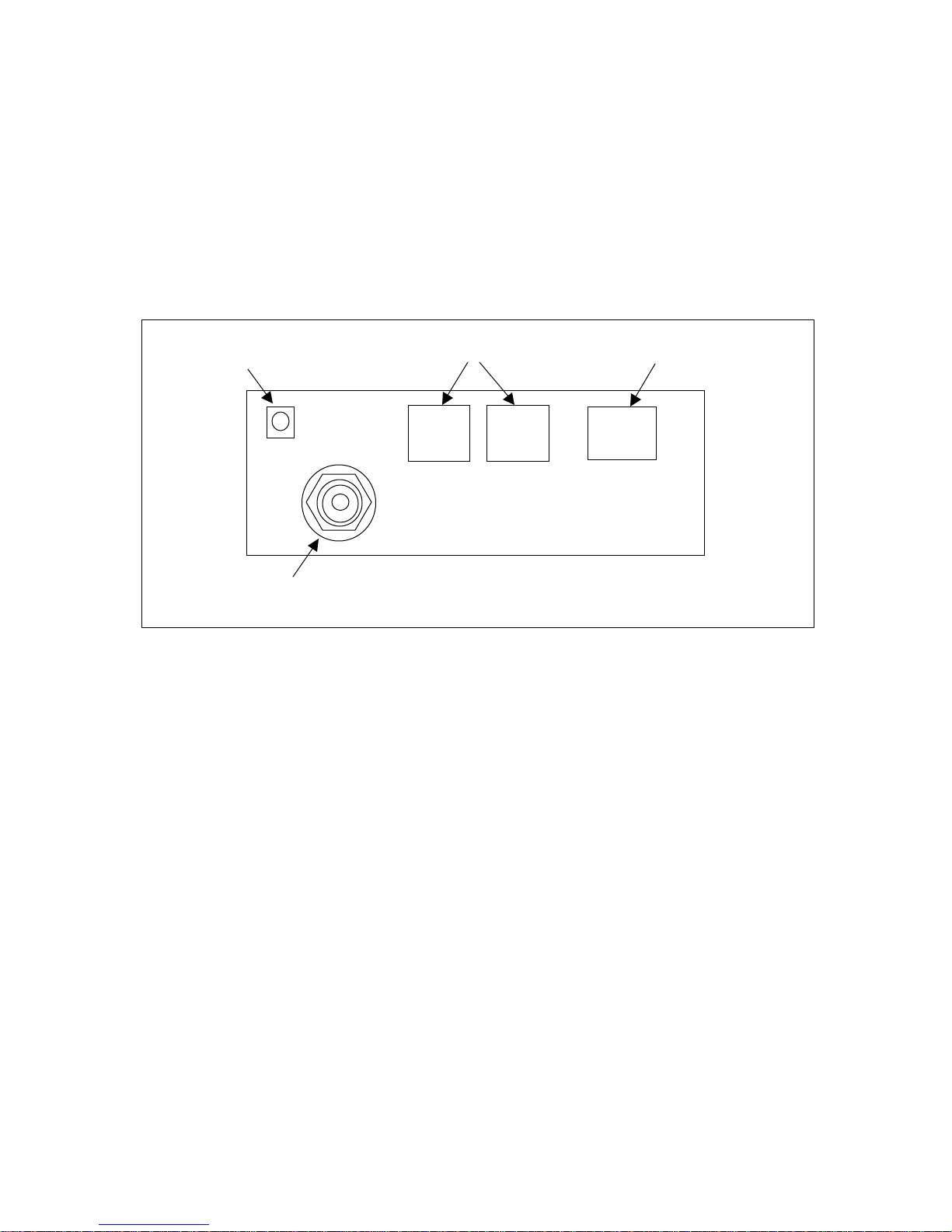
Figure 1 identifies the various connectors on the rear of the SNAP2410.
Power Connector
TNC Antenna Connector
Synchronizing Signals 10BaseT Ether net Connector
Figure 1. SNAP Rear Panel Diagram
The antenna connector is a TNC type connector. An antenna may be connected directly
to this connector. Alternatively, an antenna may be located away from the SNAP using
RF cable to connect the SNAP to the antenna. Digital Wireless does not recommend
using RF cables longer than 5 feet. If more distance is required between the SNAP and
the antenna, high-quality, low-loss RF feed line must be used.
The 10BaseT Ethernet connector is the standard RJ-45 connector. The connector is wired
to be able to connect directly to an Ethernet hub using a straight-through cable. If it is
desired to connect the SNAP directly to a PC without a hub, the SNAP must be
connected with a cross-over cable.
The synchronizing signals are provided for special applications where multiple master
SNAPs are employed in an environment with slave SNAPs that are moving. The
synchronizing signals are RS-485 levels and may be connected using an RJ-11 connector.
In most instances the synchronizing signals are not required and may be left unconnected.
The power connector is a 2-pin DIN type connector. The provided AC adapter provides a
9 volt power level to the SNAP. The SNAP can accept DC voltages ranging between
7VDC and 26VDC if alternative power supplies are to be used.
2000 Digital Wireless Corporation 2 042000
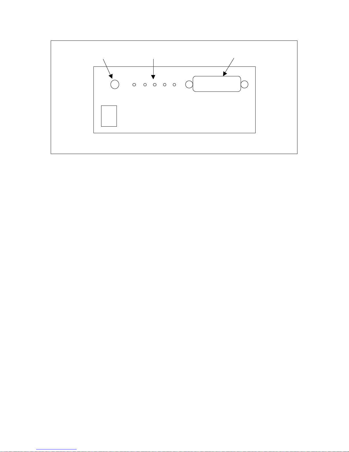
Power Switch Status Indicators
Conf iguratio n Por t
SNAP 2410
2.4 GHz SPREAD SPECTRUM WIRELESS ETHERNET MODEM
Figure 2. SNAP2410 Front Panel Diagram
The Configuration Port is an RS-232 serial port that may be used to configure the SNAP.
This is useful when the default IP address of the SNAP cannot be used with the existing
network preventing configuration through a telnet session. See the section Configuring
the SNAP for details of using this port.
SNAP Status Indicators
The PWR indicator on the front panel indicates that power is applied to the SNAP and
that the power switch is in the ON position.
TXD and RXD are indicators of data activity. They indicate the transmission and
reception of data over the Ethernet connection. Note that these LEDs can be active even
when the SNAP has no remote radios registered.
The COLL indicator is illuminated whenever packets collide on the network segment to
which the SEM is connected. As such, this is rough indicator of the level of traffic on the
network segment. If this LED is glowing brightly on a continuous basis, the throughput
of the SEM may appear to be reduced.
The LINK indicator when illuminated indicates a good connection to the Ethernet
network. If this LED is not on, it can indicate a cross-wired connection between the
SNAP and the network. It may also indicate a faulty cable connection.
Configuring the SNAP
SNAPs are shipped from the factory with default settings that include a default IP address
of 192.168.0.254. The network that the SNAP is connecting to must be compatible with
10BaseT products. The SNAP
will not
work if the network only supports 100BaseT
products. Before connecting a default configured SNAP to an active network, ask the
network system administrator to make sure that the default IP number will not cause any
2000 Digital Wireless Corporation 3 042000

problems on the network and that the SNAP will be recognized by the network. If the
default IP address conflicts with a device on the existing network, the SNAP will need to
be configured through the serial port.
The SNAP can be configured two ways. The first is through the serial port. The settings
for the serial port are 38400 baud, 8 data bits, 1 stop bit, and no parity. WinSNAP will
automatically find the appropriate serial port and configure the serial port settings for
you. The software will inform you of its progress and any problems that arise. After a
few seconds the SNAP firmware version is displayed followed by the
SNAP>
prompt.
The second configuration method is through a telnet session. Most telnet programs work
with the SNAP. Windows 95/98/NT/2000 have a telnet program that works with the
SNAP. If there are no conflicts with the default IP number, initiate a telnet session to the
SNAP. A telnet session can be started by clicking on Start->Run if you have Windows
95/98/NT/2000 and the TCP/IP client has been installed. Enter the following information
in the dialog box:
telnet 192.168.0.254
A telnet window will open up. The first line is the version of the SNAP firmware
followed by the prompt:
SNAP>
To change the IP number of the SNAP, use the ip command.
ip <xxx.xxx.xxx.xxx> {yyy.yyy.yyy.yyy}
Where x is the new IP address, and y is the optional netmask number.
Store the changed configuration parameters in non-volatile memory with the save
command:
save<CR>
The SNAP will report back the time it took to the save the information. Reset the SNAP
by typing:
reset<CR>
The SNAP can also be reset by cycling power. Whenever a reset is executed on the
SNAP, the telnet session will be lost. It will take the SNAP about 30 seconds to
reinitialize after a reset or after cycling power.
Note: The save and reset commands must be entered aft er modi f ying t he
default configuration. Failure to do so will result in the factory defaults to
be used.
2000 Digital Wireless Corporation 4 042000

SNAP OPERATION
Overview
At the most basic level, SNAPs can be thought of as Ethernet-to-serial interface adapt ers .
That is, they take data from a host application over a 10BaseT Ethernet connection,
remove the Ethernet header information, format the data for WIT2410 radios and
transmit the data to the on-board WIT2410 through a high-speed serial interface. In the
other data flow direction, the on-board WIT2410 receives data from a remote WIT2410
device. The SNAP takes this data and provides the necessary Ethernet datagram
encapsulation and transmits the datagram to the host application over the connected
network.
A SNAP can be used standalone, or a group of SNAPs can be connected together through
a 10BaseT hub to provide seamless roaming over a larger area. When seamless roaming
operation is desired, the SNAPs must be synchronized with each other. This
synchronization is accomplished either over the Ethernet network or through a
differential Sync signal when time delay devices (such as routers) are between SNAPs.
See the section on Synchronization for details.
Communication between the host application SNAPs can occur at one of two levels.
Provided with the SNAP is a library of C routines that constitute a high level API for
workstation-based applications. Alternatively, host applications can communicate with a
SNAP using the SNAP Datagram Protocol (SDP). This protocol is described in detail
later in this manual.
The SNAP has a serial Configuration port in addition to the 10BaseT port. This port
allows configuration of the SNAP without having to connect it to a network. The
WinSNAP configuration utility provided with the SNAP is used to configure the SNAP
through the serial Configuration port. Any configuration of the SNAP can be performed
using either the Configuration port or over the network.
TCP/IP Addresses
Each SNAP must be configured with a unique IP address that is appropriate for the
network where the SNAP will be used. The IP address can be set using the ip command
through the serial-port interface. The ip command takes one or two parameters. The first
parameter specifies the IP address for the SNAP, and the second optional parameter, if
present, specifies the netmask for the SNAP. If the second parameter is not used, the
netmask is set to the default netmask for the IP address specified. For example, the
command:
ip 192.168.0.1
will set the SNAP’s IP address to 192.168.0.1 and the netmask will remain
255.255.255.0.
2000 Digital Wireless Corporation 5 042000

The command:
ip 192.168.1.233 255.255.255.192
will set the SNAP’s IP address to 192.168.1.233 and will change the netmask to
255.255.255.192. The ip command without any parameters will display the current
setting of the IP address and netmask. The SNAP includes a simple ping command that
can be used to test the IP address and routing table settings.
The SNAP can also obtain its IP address from a BOOTP server if one is present in the
network. The BOOTP server will require the Ethernet hardware MAC address to be able
to assign the IP address to the SNAP. The Ethernet hardwate MAC address of the SNAP
is configured as 00:30:66:XX:YY:ZZ, where XX:YY:ZZ is the unique ID of the SNAP’s
“radio A”.
The route command can be used to modify and display the IP routing table entries. To
display the routing table, use the route list command. There will always be one entry in
the routing table that corresponds to the IP address of the SNAP. For most applications,
if any routing table entries are required, it will be sufficient to set a default route. To set
the default route, use the command:
route add default <gwaddr>
where <gwaddr> is the IP address of the default gateway (usually a router or routing
host). To remove the default route, use the command “route del default”. To add a route
to a particular network or host, use the command “route add <dest> <gw> [<netmask>]”,
where “<dest>” is the destination network or host IP address, “<gw>” is the IP address of
the gateway, and the optional “<netmask>” is the netmask which defines the destination
network.
Seamless Roami ng
The SNAP2410 allows remote radios to seamlessly roam between multiple SNAP2410.
The remote radios can also be configured not to roam if this is the required operating
condition. In order for the remote to be able to roam seamless the <wg> parameter must
be set to 2. When the RSSI (receive signal strength indictor) of the remote reaches a
certain threshold, the remote will start looking for another SNAP with a higher RSSI.
The SNAP will be notified with a CONNECT and DISCONNECT packet when a remote
leaves or connects with a SNAP.
To facilitate seamless roaming among a group of SNAPs, the SNAPs use Ethernet
packets to synchronize time relative to each other. A single “master” SNAP will
broadcast (or multicast) special UDP datagrams to the “slave” SNAPs to deliver timing
information through the network. The SNAPs can also synchronize with one another by
RJ-11 cable (telephone cable). The RJ-11 method of synchronization uses a daisy chain
fashion to connect the SNAPs together. The SNAPs need to be synchronized this way if
2000 Digital Wireless Corporation 6 042000
 Loading...