

Page 1
5436 W Crenshaw St. Tampa, FL 33634
Tel: 866-446-3595 / 813-888-9555
Fax: 813-888-9262
www.Digital-Watchdog.com
technicalsupport@dwcc.tv
Technical Support Hours: Monday-Friday
8:30am to 8:00pm Eastern Time
Before installing and using the camera, please read this manual carefully.
Be sure to keep it handy for future reference.
ABOUT MANUAL
10112011
Vandal Dome Camera
X12 Zoom V1312XW
User Manual
Page 2

32
PRECAUTIONS Table of Contents
Introduction
Camera Features
4
Parts and Descriptions
5
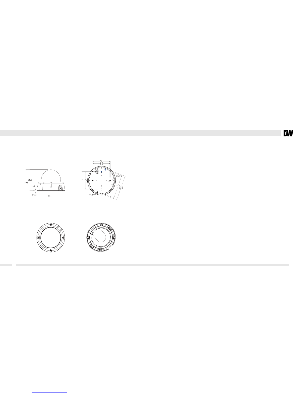
Dimensions
6
Installation
Inside the box
7
Mounting the Camera
8
Junction Box Installation
9
Wall Mount
10
Pendant Mount
11
Corner Mount
12
Connecting Cables
13
Adjusting the 3 Axis Gimbal
14
Control Board
15
Programming OSD Menu and Glossary
16-17
Troubleshooting
18
Warranty and Service
19-20
Specications
21-22
FCC COMPLIANCE
■
Do not open or modify.
■
Do not open the case except during maintenance and installation,
for it may be dangerous and can cause damages.
■
Do not put objects into the unit.
■
Keep metal objects and ammable substances from entering the camera. It can cause re, short- circuits,
or other damages.
■
Be careful when handling the unit.
■
To prevent damages, do not drop the camera or subject it to shock or vibration.
■
Do not install near electric or magnetic elds.
■
Protect from humidity and dust.
■
Protect from high temperature.
■
Be careful when installing near the ceiling of a kitchen or a boiler room, as the temperature may rise to
high levels.
■
Cleaning
■
To remove dirt from the case, moisten a soft cloth with a soft detergent solution and wipe.
■
Mounting Surface
■
The material of the mounting surface must be strong enough to support the camera.
This equipment has been tested and found to comply with the limits for a Class B digital device, pursuant
to Part 15 of the FCC rules. These limits are designed to Provide reasonable protection against harmful
interference .when the equipment is operated in a residential environment. This equipment generates, uses,
and radiates radio frequency energy; and if it is not installed and used in accordance with the instruction
manual, it may cause harmful interference to radio communications.
WARNING : Changes or modications are not expressly approved by the manufacturer.
Page 3
54
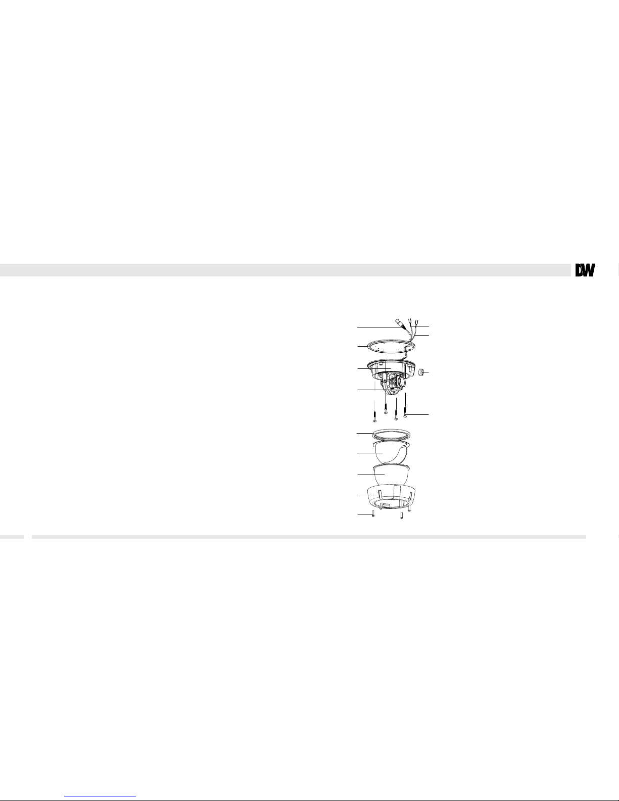
PART & DESCRIPTIONS
*
FEATURES
*
■
1/4" Sony Ex-View HAD Double Scan CCD
■
560 TV Lines
■
3.6~44.3mm Varifocal Auto Iris Lens
■
12X Digital Zoom
■
Electronic Day and Night with Color Removal Circuit
■
WDR (Wide Dynamic Range)
■
3D-DNR (3D Digital Noise Reduction)
■
Star-Light a.k.a. Sens-Up (Super Low Light Technology)
■
DIS (Digital Image Stabilizer)
■
Programmable Privacy Zone (12) & Motion Detection
■
AGC / BLC / AWB
■
On-Screen Menu Programming with Built-in Joystick
■
Secondary Video-BNC Output for Easy Installation
■
Auto Sensing 24VAC/12VDC with Line Lock
■
RS-485 Built-in
Lens
Video Output Connector - BNC
Power input Connctor
12VDC/24VAC Dual Voltage
RS485 : BK(D+), WH(D-)
Rubber Band
Black Dome Insert
Bubble
Upper case
Assembly Screws
T20 M4X16
NPT PLUG
Bottom Case
Rubber Pad
Mounting Screws
Page 4
76
INSTALLATION
*
Parts Included with DW Camera
1. USER MANUAL
2. MOUNTING TEMPLATE
3. FOUR4 SCREW AND FOUR4 DRY WALL ANCHORS
4. 2ND VIDEO JACK
5. LWRENCH
6. TOOL 0.89MM
7. TOOL 1.5/2.0MM
TOP VIEW
DIMENSIONS IN MILLIMETERS
*
UNITS : MM
Required Tools (Not Included)
PHILLIPS HEAD SCREWDRIVER
Page 5

98
Instructions to Mount the Camera Junction Box Adapter Installation Instructions
1. Pull wires through and make connections.
Refer to page 13. Use mounting template to
mount camera with dry wall mounts and wood
screws.
1. Check to see all parts are
in the box.
4. Attach the camera to the
junc tion box using the
machine screws.
2. Use the drywall anchors
and wood screws to
mount the junction box
and rubber gasket to the wall.
5. Attach the camera
housing to the junction
box using the machine
screws.
3. Insert wires through
the wall and make the
appropriate connections.
2. Adjust the camera (pan, tilt, zoom).
See page 14 for details.
3. Use the joystick to adjust the OSD menu.
See page 15, 16, 17 for details.
4. Attach the camera housing to the
junction box using the machine screws.
Page 6

1110
Junction Box Adapter Installation Instructions Pendant Installation Instructions
1. Check to see all parts are
in the box.
1. Check to see all parts are
in the box.
4.
Use the mounting template to
make pilot holes. Use the dry
wall anchors and wood
screws to attach the assembly
to the wall.
4. Attach the camera to the
pendant mount using the
machine screws.
2. Insert the wires from the
camera through the wall
mount housing.
2. Attach the top shield to
the pendant mount.
5. Attach the camera housing
to the xture.
5. Attach the camera housing
to the xture.
6. Use the mounting template
to make pilot holes. Mount the
camera assembly to the ceiling
using wall mount anchors and
machine screws.
3. Attach the camera to the
wall mount housing.
3. Slide the wires from
the camera through the
pendant mount.
Page 7

1312
Corner Mount Installation Instructions
1. Check to see all parts are in the box. 2. Attach the two compression ttings to
the corner bracket.
3. Attach the wall mount to the corner
bracket with the 4 machine screws.
4. Attach the assembly to a wall corner with
dry wall anchors and wood screws.
CONNECTING TO MONITORS
*
Follow the diagram below to make proper connections to the CRT Monitor or the Monitor.
Power connection - 12VDC/24VAC Dual Voltage(Auto polarity detection and protection)
All camera are equipped with a service monitor output on the camera module.
Right
Left
Up
Down
12VDC / 24VDC
CCTV Monitor
Monitor
30cm
2nd Video Output
Page 8

1514
ADJUSTING THE 3-AXIS GIMBAL
*
CONTROL BOARD
*
The Gimbal Mechanism Yields Maximum Rotation And Placement As Shown Below.
Z-Axis : Rotation 360
º
Y-Axis : Tilting 90º / 82º IR LED
X-Axis : Panning 360
º
Rotation 360
o
Panning 360
o
Tilting 360
o
Joystick
Controller
CON2
CON1
RIGHT
UP
DOWN
LEFT
CONTROL BOARD FUNCTIONS
1. Joystick Controller Functional control of O.S.D.
(On Screen Display)
2. CON1 Second Video Output Connector
3. CON2 RS-485 Connector
Page 9

1716
MAIN MENU Description
CAMERA SET Camera related functions and data.
INTELLIGENCE Motion detection, and more.
PRIVACY ZONE Privacy related settings
PRESET SET Preset position and Preset ID
OTHER SET Congure for Factory Defaults, and more.
COMMUNICATION Communication set.
SYSTEM INFO Displays the system information.
LANGUAGE Select a language on the OSD menu.
MODULE OSD MENU AND GLOSSARY
*
CAMERA SET Description Setting Options
CAMERA ID Make the camera ID and set the place. 54 characters.(2 line) OFF / ON
IRIS ALC/MANUAL Iris select. Setting the BLC and WDR function. ALC(-32~32) / MANUAL(-32~32)
AGC(MOTION) Setting the Max Gain under the low light. OFF / ON(Max.Level Setting)
DNR Digital Noise Reduction : Produces less noise and more color at night. OFF / LOW / MID / HIGH/ USER(1~16)
SHUTTER Set the shutter speed. (High shutter speed) 1/60(1/50) ~ 10Ksec
SENS-UP Super Low Light Technology. Sets the slow shutter speed. FIX X2 ~ OFF ~ AUTO X256
FLICKERLESS Shutter speed OFF / ON
DIS
Digital Image Stabilization : Removes jitters caused by movement or vibrations.
OFF / ON
DAY/NIGHT DayNight Mode , Level set. AUTO / EXT / DAY / NIGHT
WHITE BAL White Balance Mode
ATW1 / ATW2 / AWC / 3200K / 5600K
FOCUS MODE Select the Focus Mode MF / ONEAF / AF
ZOOM SPEED ZOOM Speed set 1~4
DISPLAY ZOOM ZOOM RATIO display OFF / ON
DIGITAL ZOOM Digital Zoom ratio set OFF ~ X12
DETAIL Aperture gain set 0~3
V-SYNC Internal/Linelock mode set INTERNAL / LINE LOCK
AGC COLOR SUP AGC Color Suppression : Color will be reduced at the AGC function. LOW / MID / HIGH
REVERSE Horizontal/Vertical Reverse OFF / H / V / HV
POSI/NEGA Positive or Negative Video output set - / +
PIP Picture In Picture at Digital Zoom operation OFF / ON
INTELLIGENCE Description Setting Options
MOTION Motion detection function OFF / TRACKING / DETECTION
ADVANCED Advanced Motion detection function OFF / FIXED,MOVED
MASK AREA
Set the motion detection exception area
1 ~ 4
DISPLAY Motion Detection display ON/OFF OFF / ON
SENSITIVITY Motion Detection sensitivity 1 ~ 7
RESOLUTION Motion Detection resolution 1 ~ 5
ALARM OUT Alarm out set OFF / ON
PRIVACY ZONE Description Setting Options
PRIVACY SET Set the privacy zone 1 ~12
STYLE Set the privacy style COLOR / MOSAIC 1~4
PRESET Description Setting Options
PRESET SET Set the preset 0 ~ 255
OTHER SET Description Setting Options
LANGUAGE select the language of OSD menu
ENGLISH / FRANCAIS / ESPANOL /JAPANESE / KOREAN /
PROTUGUES
FACTORY DEFAULTS
Set the Factory default setting
OSD COLOR OSD menu color set BW / R / G / B
COMMUNICATION Description Setting Options
PROTOCOL Set protocol of RS-485 device.
PELCO-D/HONEYWELL/SAMSUNG-E,T/VICON/ PANASONIC /
BOSCH/PELCO-P/GE
BAUD RATE Set Baud Rate for RS-485 communication. 2400 / 4800 / 9600 / 19200
ADDRESS Set Camera ID to enable commands from user. 1 ~ 255
SYSTEM INFO Description Setting Options
SYSTEM INFO Camera setting Information
Page 10

1918
Before sending your camera for repair, check the following or contact our technical specialist.
No VIDEO
Check the coaxial cable and make sure it is connected securely.
Check the lens’ iris adjustment at the menu setup of the camera.
Check the power supply and make sure the camera has the proper voltage and current.
Out-of-Focus VIDEO
Check the clear dome cover and the lens for dirt or ngerprints. Use a soft cloth and gently clean.
Check the lens manual focal and zoom adjustment. Field test monitor is recommended.
TROUBSHOOTING
Digital Watchdog (referred to as “the Warrantor”)
warrants the Camera Series against defects in
materials or workmanship as follows.
LABOR : For the initial two (2) years from the date of original purchase,
if the camera is determined to be defective,
the Warrantor will repair or replace the unit, with new or refurbished
product at its option, at no charge.
PARTS : In addition, the Warrantor will supply
replacement parts for the initial two (2) years.
To obtain warranty or out of warranty service,
please contact a Technical Support Representative at
1-866-446-3595 Monday through Friday from 8:30AM to 8:00PM Eastern.
A purchase receipt or other proof of the original purchase date is required
before warranty service is rendered. This warranty only covers failures due to
defects in materials and workmanship which arise during normal use.
This warranty does not cover damage which occurs in shipment or failures
which are caused by products not supplied by the Warrantor or failures
which result from accident, misuse, abuse, neglect, mishandling,
misapplication, alteration, modication, faulty installation, set-up adjustments,
improper antenna, inadequate signal pickup, maladjustment of consumer controls,
improper operation, power line surge, improper voltage supply, lightning damage,
rental use of the product or service by anyone other than an authorized repair
facility or damage that is attributable to acts of God.
WARRANTY INFORMATION*
Page 11

2120
SPECIFICATIONS
*
ITEMS SUB-ITEMS X12_ZOOM_N
CCD
Device
SONY 1/4” ExView-HAD PS CCD(ICX-448)
Total 811 x 508
Eective 768 x 494
Sync.
Inter. H/V 15,734 / 59.94Hz
LL H/V 15,750 / 60Hz
SYSTEM INFO
Horizontal/Vertical Resolution
more than 560(Color)/600(BW) TV Lines
Performance
Minimum illumination
(F1.6/Wide)
Color mode 50 IRE 25 IRE
Sens O 1.2 Lux 0.6 Lux
Sens x256 0.004 Lux 0.002 Lux
BW mode 50 IRE 25 IRE
Sens O 0.12 Lux 0.06 Lux
Sens x256 0.0004 Lux 0.0002 Lux
S/N Ratio 52dB
Lens
focal length, F number f=3.6~44.3mm, F1.6( Wide)/F2.0(Tele)
Drive Type Auto (DC)
M.O.D Wide: 0.2m , Tele: 0.8m
View Angle Tele: 4.64°(H) x 3.52°(V), Wide: 54.44°(H) x 41.42°(V)
DFunctions
OSD E/F/S/J/P , (E/K) E/F/G/S/I , (E/R/Po/T/Cz), (Chinese)
Privacy Zone 12ea (Square)
Day&Night COLOR/BW/AUTO/EXT (with D/N Filter Assy)
Motion Detection O/On(1ea) ※Mask Area 4ea
D-Zoom x1~x12 (x0.1 STEP)
High Speed Shutter 1/60(1/50) ~ 1/10Ksec
Flickerless O/On
Sens-Up (Star-Light) x2 ~ x256
There are no express warranties except as listed above.
The Warrantor will not be liable for incidental or consequential
damages (including, without limitation, damage to recording media)
resulting from the use of these products, or arising out of any breach
of the warranty. All express and implied warranties, including the
warranties of merchantability and tness for particular purpose,
are limited to the applicable warranty period set forth above.
Some states do not allow the exclusion or limitation of incidental
or consequential damages, or limitations on how long an implied
warranty lasts, so the above exclusions or limitations may not
apply to you. This warranty gives you specic legal rights, and you
may also have other rights that vary from state to state.
If the problem is not handled to your satisfaction,
then write to the Address listed on the next page.
Service calls which do not involve defective materials or
workmanship as determined by the Warrantor, in its sole
discretion, are not covered. Costs of such service calls are
the responsibility of the purchaser.
LIMITS AND EXCLUSIONS*
Page 12

2322
MEMO
BLC O/On (Area Setting)
AGC O/On (Max.Level Setting)
ALC(Auto Level Control) Auto(DC)/Manual (Level Control)
Line Lock O/On (Phase Control)
Camera ID O/On (Max. 54ea/2Line)
White Balance
ATW1/ATW2/AWC/MANUAL
(ATW1 : 2,500 ~ 9,500°K, ATW2 : 2,000 ~ 10,000°K)
DNR O/On (Adaptive 3D+2D)
DIS O/On
PRESET O/On (256ea
)
WDR O/On (x128/NTSC, x160/PAL)
Intelligent Video Yes (Moved/Fixed)
Etc. Function Detail, Reverse(H/V), Posi/Nega, PIP
Video Output VBS 1.0V p-p (75ohm Terminated)
Power
Power Input DC : +10V ~ 16V / AC : 20V ~ 28V
Power Consumption DC : Max 2.8[ W] AC : Max 3.2[W]
Operating Temperature Absolute : -10°C ~ +50°C
Operating Humidity Less than 90%
 Loading...