

Page 1
’
Quick Start Guide
Quick Start Guide
DW-HDSPOTMOD DW-HDSPOTMOD16
DW-HDSPOTMOD DW-HDSPOTMOD16
Default Login Information
Username: admin Password: no pa ssword
WHAT S IN THE BOX
Quick Start G uide 1 Set 12V DC power cable 1 Set
USB mouse 1 Set
NOTE: Downloa d All Your Support Materi als and Tools in One Place
1. Go to: http://www.digital-watchdog.com/support-download/
2. Search your pr oduct by entering the p art number in the ‘Search by Product’ search bar. Results for applicable
part number s will populate autom atically based on th e part number you ente r.
3. Click ‘Search’. All supporte d materials, includ ing manuals, Quic k Start Guides (QSG ), software and rmwa re will
appear in the re sults.
Attention: Th is document is inten ded to serve as a quic k reference for init ial set-up. It is reco mmended that
the user read the entire instruction manual for complete and proper installation and usage.
Tel: +1 (866) 446-3595 / (813) 888-9555
digital-watchdog.com
Technical Suppor t Hours: 9:00AM – 8:00PM EST, Monday thr u Friday
The Digital Watchdog Spot™ monitoring module requires only 2 steps to complete the installation—local
conguration off-site, and power and monitor connection at the site.
STEP 1 – SETTING UP THE SPOT MONITORING MODULE OFF SITE
1. Connect the module to an appropriate power supply.
2. Connect the module to a local monitor off site for conguration.
3. Make sure the m odule is connected to the same net work as your IP cameras, Unive rsal HD over
Coax
®
VMAX® A1™ DVRs or VMAX IP Plu s ™ NVR.
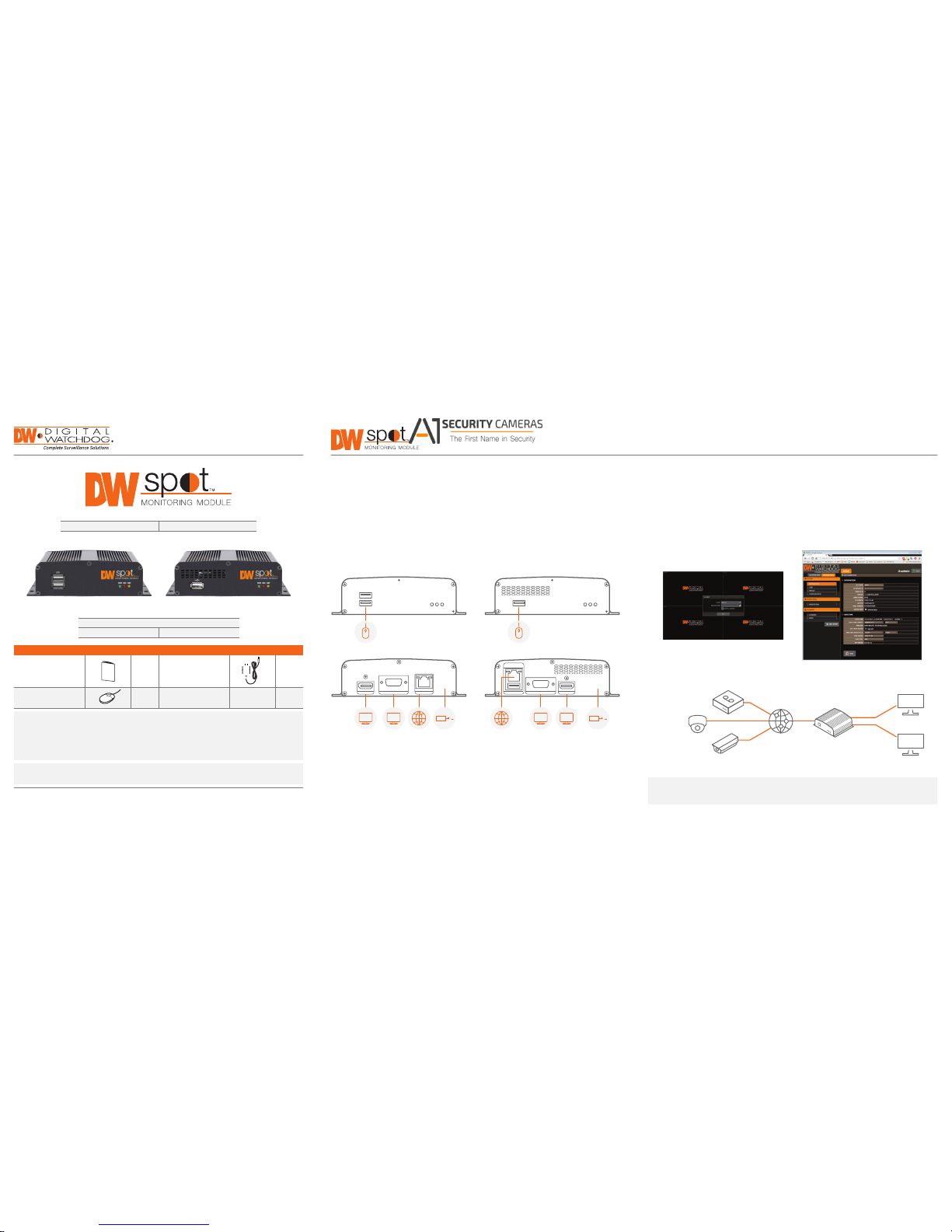
DW-HDSPOTMOD DW-HDSPOTMOD16
FRONT PANEL FRONT PANEL
BACK PANEL
USB
DC 12V
LANVGA OUTHD OUT
BACK PANEL
PWR REC
USB
DC 12V
USB
LAN
VGA OUT HD OUT
NETPWR REC NET
POWER
SUPPLY
POWER
SUPPLY
NETWORK PORT
USB MOUSE
NETWORK PORT
USB MOUSE
VGA VGA HD HD
SAFETY TIPS
1. During t he boot up process, the module sho uld not be interrupted by pressing a ny buttons on the
mouse. Do not unplug th e power adapter or turn the module of f during the boot up process.
2. A UPS (uninter rupted power supply) is highly rec ommended to prevent damage to the mo dule during
a power outage.
STEP 2 – POWERING UP THE SPOT MONITORING MODULE
1. When the m odule boots up, it will be in protective mod e. This means you will not be able to acc ess
the module’s setup menu until yo u enter the proper username an d password.
2. To unlock the modul e, right-click anywhere on the sc reen. The login screen will a ppear. (Default
username / pass word: admin / no password)
3. When the m odule boots up for the rst time, you will b e guided through the startup w izard.
4. You can also acce ss the Spot monitor for basic setup vi a its web browser.
ONVIF
IP Cameras
VMAX
®
A1™ DVRs
and VMAX
®
IP Plus™ NVRs
Network
DW Spot
VGA Output
HDMI Output
HD
VGA
NOTE: The Digital Watchdog spot monitoring module supports up to 16 supported devices
registered, with sin gle, quad and 16-channel view.
Available from A1 Security Cameras
www.a1securitycameras.com email: sales@a1securitycameras.com
Page 2
Quick Start Guide
b. Camera se arch – To search for any ONVIF conformant IP c amera:
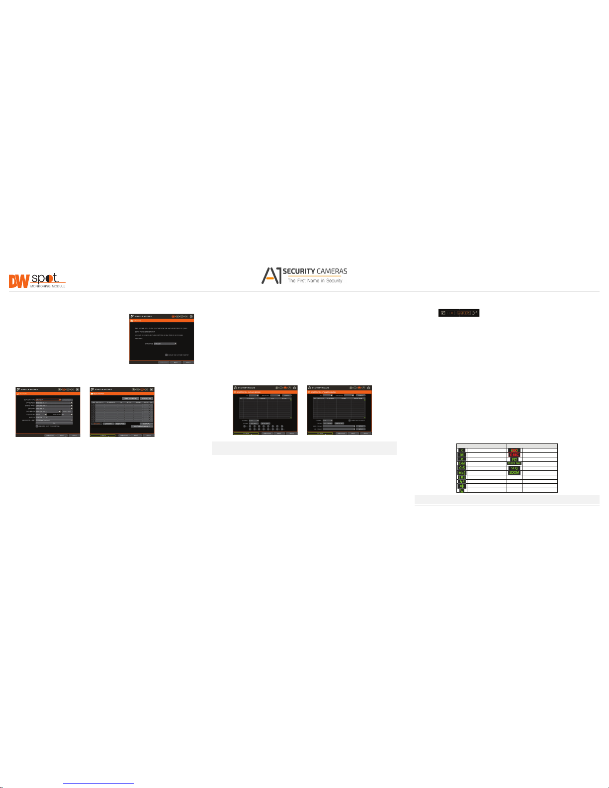
STEP 3 – STARTUP WIZARD STEP 5 – SYSTEM OPERATIONS
• P ress the ‘SEARCH (CAM)’ button. The system w ill scan the network automatic ally. You can
also press the SE ARCH button to scan the network ag ain.
Menu bar
1. Follow the st artup wizard’s instructions to setup t he
• Select the came ra you wish to register from the search r esults and press the ‘GET INFO’
You can view the Spot monitori ng module’s menu bar by moving the cursor of a US B mouse over the
module’s basic settings, including language, network and
button to obtain the dev ice’s streaming prole. DETAIL INFO allows you to get more
bottom of the module’s screen. T he following options will appe ar:
device search an d registration. At any time you can skip
information on the de vice’s individual streams and setup e ach of the camera’s streams
steps, go back, or exit the w izard and setup the module
• O pen the system menu.
rem otel y.
manually.
• V iew a selected channel in fu ll screen mode.
• You can select multiple c ameras by checking the ‘CAMER A MULTI SELECT’ button. Cameras
2. Language – Select the ap propriate language from the
selected will be highlighted in orange.
• Switch to view mode.
drop-down menu opti ons. Press ‘Apply’ to save and next to
• If necessar y, select the which stream from the ca mera to view (depend on camera’s
• Start/stop sequence.
move to the next step.
capabilities).
• Select a specic channel from the 16 registered channels.
3. Set the module’s network settings to matc h your network’s
• If needed, enter the u ser ID and password for the device you a re registering.
• Power down the spot monitoring module.
requirements. It is re commended to set the network t ype
• Click ‘APPLY’ to register your device. Camera s will be registered in the order in w hich they
to DHCP and let the modul e auto-detect the network’s
• Pin the menu bar to keep it i n view.
appear. Cameras that are a lready registered will be show n in gray.
settings, then ch ange the type to static. Please cont act
Pop-Up menu
your network administrator for additional information.
Press ‘Apply’ to save and next to move to the n ext step.
When right-clicking on the module’s display, the following options will appear:
• DISPLAY MODE: select the display option.
• C HANGE NEXT CH: show the nex t channel.
• SEQUENCE: start /stop sequence view.
• F REEZE: freeze the current view.
• SYSTEM STATUS: show the system statu s in real time.
• M ENU: open the setup menu screen.
Display icons
For DVRs and NVRs, the sp ot monitoring module can show ea ch channel’s current status based on
the settings in the DVR o r NVR. When supported, some of t he following icons may appear o n the
4.
5.
Search and registe r all supported devices wi th the module. You can search for ONVIF conf ormant IP
cameras or VMA X IP Plus ™ NVR.
The module’s registration s creen allows you to detect all the cam eras in your network and
automatically add th em to the NVR. Select one of the follow ing options:
a. DVR/NVR search – To search for VM AX IP Plus
™
NVR:
STEP 4 – CONNECT THE MONITOR ON SITE
NOTE: Uni versal HD over Coax® VMAX® A1™ DVRs must be added MA NUALLY using RTSP
protocol.
channel’s display.
• Press the ‘SEARCH (DV R/NVR)’ button. The system will sca n the network automatically. You
can also press the S EARCH button to scan the networ k again.
Once all the setup for the module is completed off site:
• Select the DVR/N VR you wish to register from the searc h results and press the ‘GET
INFO’ button to obtain the de vice’s streaming prole. DETAIL INFO allows you to get mo re
information on the de vice’s individual streams.
1. Install the module in its per manent location.
2. Connect the module to a proper power supply.
Icon on Each Channel Screen Icon on Main Screen
Continuous Recording No HDD or HDD Failure
Motion Recording Emergency Recording
Sensor Recording PTZ Mode
Continuous & Motion Recording Warning for Overheated Temp
Continuous & Sensor Recording Sequence Mode
Motion & Sensor Recording Digital Zoom Mode
Sensor Activated
Motion Activated
Audio Channel
PTZ Camera
• I f necessary, enter the user ID and p assword for the device you are registe ring.
3. Connect the module to a true HD or VG A monitor.
NOTE: Scre en shots are for reference only. Actual GU I may differ.
• You can a lso select which channel s from the DVR/NVR you wish to registe r.
4. Power up the module, and make sure the di splay setup is correct.
Copyright © Di gital Watchdog. All r ights reserved.
• C lick ‘APPLY’ to register your device.
Rev Date: 1/18 Specications and pricing are subject to change without notice.
Available from A1 Security Cameras
www.a1securitycameras.com email: sales@a1securitycameras.com
 Loading...