

Digital Watchdog Nexus User Manual

Digital Watchdog® Nexus NVRTM
User Manual
Manual Edition 022012– February 2012
©2000-2012 DIGITAL WATCHDOG, INC.
All Rights Reserved.
No part of this document may be reproduced by any means, electronic or mechanical, for any purpose, except as expressed in the Software
License Agreement. DIGITAL WATCHDOG shall not be liable for technical or editorial errors or omissions contained herein. The information in
this document is subject to change without notice.
The information in this publication is provided as is without warranty of any kind. The entire risk arising out of the use of this information
remains with the recipient. In no event shall DIGITAL WATCHDOG be liable for any direct, consequential, incidental, special, punitive, or other
damages whatsoever (including without limitation, damages for loss of business profits, business interruption, or loss of business information),
even if DIGITAL WATCHDOG has been advised of the possibility of such damages or whether in an action, contract or tort, including
negligence.
This software and documentation are copyrighted. All other rights, including ownership of the software, are reserved to DIGITAL WATCHDOG,
INC., DIGITAL WATCHDOG, Digital Watchdog, Nexus, DW-Pro 7000 Series, and DW-Pro 9000 Series are registered trademarks of DIGITAL
WATCHDOG, INC., in the United States and elsewhere; Windows and Windows 7 Embedded are registered trademarks of Microsoft
Corporation. All other brand and product names are trademarks or registered trademarks of their respective owners.
DIGITAL WATCHDOG, INC.
Tampa, FL ● USA

SAFETY INFORMATION_______________________
Read User Manual. After unpacking this product, read the user manual carefully, and follow all the operating and other instructions.
Power Sources. This product should be operated only from the type of power sources indicated on the label. If you are not sure of the
type of power supply to your home or business, consult your product dealer or local power company.
Ventilation. Slots and openings in the cabinet are provided for ventilation. Proper ventilation ensures reliable operation of the product and
protects it from overheating. These openings must not be blocked or covered. The product should not be placed in a built-in installation
such as a bookcase or rack, unless proper ventilation is provided or the manufacturer’s instructions have been adhered to.
Heat. The product should be situated away from heat sources such as radiators, heat registers, stoves, or other products that produce
heat.
Water and Moisture. Do not use this product near water. Do not exceed the humidity specifications for the product.
Cleaning. Unplug this product from the wall outlet before cleaning. Do not use liquid cleaners or aerosol cleaners. Use a damp cloth for
cleaning.
Power Cord Protection. Power-supply cords should be routed so that they are not to be walked on or pinched by items placed against
them. Pay particular attention to cords, convenience receptacles, and the points where they exit from the product.
Overloading. Do not overload wall outlets, extension cords, or integral convenience receptacles as this can result in a risk of fire or
electrical shock.
UPS (Uninterruptible Power Supply). Highly recommended.
Object and Liquid Entry Points. Never insert foreign objects into the NVR unit, as they may touch dangerous voltage points or short-out
parts that could result in a fire or electrical shock. Only insert the media types approved by Digital Watchdog. Never spill liquid of any kind
on the product.
Accessories. Do not place this product on an unstable cart, stand, tripod, bracket, or table. The product may fall, causing serious damage
to the product.
Burden. Do not place a heavy object or step on the product. The object may fall, causing serious personal injury and serious damage to
the product.
Servicing. Do not attempt to service this product yourself, as opening or removing covers may expose you to dangerous voltage or other
hazards. Refer all servicing to qualified personnel.
Replacement Parts. When replacement parts are required, be sure the service technician has used replacement parts specified by the
manufacturer or have same characteristics as the original part. Unauthorized substitutions may result in fire, electric shock, or other
hazards.
Safety Check. Upon completion of any service or repairs to this unit, ask the service technician to perform safety checks to determine the
unit is in proper operating condition.
Nexus Manual 022012 | 3

WARNING
SYMBOLS
To reduce the risk of electrical shock, do not expose this appliance to rain or moisture.
Dangerous high voltages are present inside the enclosure.
Do not open the cabinet.
Refer servicing to qualified personnel only.
The following words and symbols mark special messages throughout this guide:
WARNING: Text emphasized in this manner indicates that failure to follow directions could result in bodily harm or loss of life.
CAUTION: Text emphasized in this manner indicates that failure to follow directions could result in damage to equipment or loss of
information.

TABLE OF CONTENTS
CHAPTER 1: INTRODUCTION 9
1.1 CONTROLS AND CONNECTIONS 10
1.2 COMPONENTS 12
1.2.1 INCLUDED HARDWARE 12
1.2.2 KEYBOARD SETUP 13
1.2.3 MOUSE SETUP 13
1.2.4 MONITOR SETUP 13
1.3 SETTING THE DATE AND TIME 14
1.4 ACCESSING THE NVR UTILITY 14
1.4.1 EXPORTING SETTINGS 14
1.4.2 IMPORTING SETTINGS 15
1.4.3 CHANGING VIDEO SETTINGS 15
1.4.4 SETTING THE NVR IP ADDRESS 15
1.5 SCREEN DISPLAY AND LIVE OPTIONS 16
1.5.1 LOOP 17
1.5.2 LIVE CAMERA OPTIONS 17
1.5.3 LIVE DIGITAL ZOOM 17
1.5.4 INSTANT RECORDING 18
1.6 CAMERA VIEW 19
1.6.1 RECORDING STATUS INDICATOR 19
1.6.2 SPECIAL RECORDING 20
1.6.3 SCREEN DIVISION BUTTONS 20
CHAPTER 2: SETUP OPTIONS 21
2.1 CAMERA SETUP 22
2.2 NETWORK VIDEO 23
2.2.1 CONNECTING A NETWORK DEVICE MANUALLY 24
2.2.2 CONNECTING A NETWORK DEVICE USING CAMERA FINDER 24
2.2.3 ASSIGNING A NETWORK DEVICE TO A CHANNEL 24
2.2.4 ASSIGNING AUDIO CHANNELS TO A NETWORK DEVICE 25
2.2.5 CAMERA CONFIGURATION 26
Nexus Manual 022012 | 5

2.2.6 ACCESSING THE CONFIGURATION MENU 27
2.2.7 DISPLAYING MORE COLUMNS 27
2.3 MOTION 28
2.3.1 CREATING A MOTION AREA 29
2.4 GENERAL 30
2.4.1 VOICE WARNING 31
2.4.2 VOLUME 31
2.4.3 AUTO SEQUENCE SETTING 32
2.4.4 CREATING CUSTOM AUTO SEQUENCE 32
2.5 SCHEDULE 33
2.5.1 RECORDING SCHEDULE 33
2.5.2 CREATING A RECORDING SCHEDULE 33
2.5.3 SENSOR SCHEDULE 34
2.5.4 CREATING A SENSOR SCHEDULE 34
2.5.5 SCHEDULING ALARM EVENTS 35
2.5.6 EMERGENCY AGENT SCHEDULE 35
2.5.7 SPECIAL DAY SCHEDULE 36
2.5.8 SYSTEM RESTART SETUP 36
2.5.9 CREATING A SYSTEM RESTART SCHEDULE 37
2.6 NETWORK 38
2.7 ADMINISTRATION 39
2.7.1 DISK MANAGEMENT 40
2.7.2 USER MANAGEMENT 40
2.7.3 ADDING A NEW USER 41
2.7.4 CHANGING ADMINISTRATOR PASSWORD 41
2.7.5 DEFAULT ADMINISTRATOR PASSWORD 41
2.7.6 SETUP LOG MANAGEMENT OPTIONS 42
2.7.7 STATUS CHECK / EMAIL 42
2.8 INFORMATION 45
2.9 PAN / TILT / ZOOM (PTZ) 46
2.9.1 PTZ SETUP TAB 46
2.9.2 ENABLE THE PTZ SETTINGS 46
2.9.3 SUPPORTED PTZ PROTOCOLS 47
2.9.4 ADVANCED PTZ CAMERA 48
2.9.5 PTZ ADDRESS SETTINGS 49
2.9.6 ACCESSING THE PTZ MENUS 49
2.9.7 CONTROLLING A PTZ CAMERA 50
2.9.8 UNDERSTANDING TOURS 51
2.9.9 PTZ TOUR SCHEDULE 51
CHAPTER 3: SEARCH OPTIONS 53
3.1 SEARCH / PLAYBACK OVERVIEW 53
3.1.1 PLAYBACK CONTROLS 54

3.1.2 PERFORMING A BASIC SEARCH 54
3.1.3 BACKUP SEARCH 55
3.1.4 ADJUSTING THE BRIGHTNESS OF AN IMAGE 55
3.1.5 ZOOMING IN ON A RECORDED IMAGE 55
3.1.6 TIME SYNC 55
3.1.7 CLEAN IMAGE 56
3.1.8 BOOKMARKS 56
3.2 PRINTING AN IMAGE 57
3.3 DAYLIGHT SAVINGS TIME 57
3.4 SAVE AS JPEG / AVI 57
3.5 SINGLE CLIP BACKUP 58
3.5.1 SINGLE CLIP BACKUP USING BOOKMARK DATA 59
3.6 INDEX SEARCH 59
3.6.1 PERFORMING AN INDEX SEARCH 59
3.7 PREVIEW SEARCH 61
3.7.1 PERFORMING A PREVIEW SEARCH 61
3.8 STATUS SEARCH 62
3.8.1 PERFORMING A STATUS SEARCH 62
3.9 OBJECT SEARCH 63
3.9.1 PERFORMING AN OBJECT SEARCH 64
3.10 AUDIO PLAYBACK 64
3.11 SEARCH IN LIVE 65
3.12 BACKING UP VIDEO DATA 66
3.12.1 NERO® EXPRESS 66
3.12.2 GENERAL SCREEN OVERVIEW 67
CHAPTER 4: INCLUDED SOFTWARE 69
4.1 WEB VIEWER 69
4.1.1 CONFIGURING SERVER 70
4.1.2 CONNECT TO NVR USING WEB VIEWER 70
4.1.3 CLOSING THE WEB VIEWER 70
4.2 EMERGENCY AGENT 71
4.2.1 CONFIGURING THE NVR 71
4.2.2 CONFIGURING THE CLIENT PC 72
4.2.3 SETUP WINDOW 72
4.2.4 EMERGENCY AGENT WINDOW 73
4.2.5 FILTER EVENT LIST 73
4.2.6 SEARCH ALARM WINDOW 74
4.2.7 VIEW RECORDED VIDEO 74
Nexus Manual 022012 | 7

4.2.8 EXPORTING VIDEO 75
4.4 REMOTE SOFTWARE 75
4.4.1 REMOTE CLIENT MINIMUM REQUIREMENTS 76
4.4.2 RECOMMENDED REQUIREMENTS 76
4.4.3 REMOTE SOFTWARE SETUP 77
4.5 DIGITAL VERIFIER 79
4.5.1 INSTALLING DIGITAL VERIFIER 79
4.5.2 USING THE DIGITAL VERIFIER 79
4.6 BACKUP VIEWER 80
4.6.1 INSTALLING BACKUP VIEWER 80
4.6.2 LOADING VIDEO FROM DVD OR HARD DRIVE 80
4.7 DW VIDEO MANAGEMENT SOFTWARE 81
4.7.1 CONFIGURING THE SERVER 81
4.7.2 CONNECTING TO AN NVR 81
CHAPTER 5: LAN / ISDN / PTSN CONNECTIONS 82
5.1 LAN OVERVIEW 82
5.2 CONNECTING TO A LAN USING TCP / IP 82
5.2.1 CONFIGURING TCP / IP SETTINGS 82
Chapter 1: INTRODUCTION
PRODUCT DESCRIPTION
Nexus is a cutting-edge Network Video Recording (NVR) device that has been designed to support most major brands of IP cameras,
megapixel cameras, and video encoders. It can record up to 32 IP cameras both locally and globally via the internet. Nexus enables you to
configure, view, search, export, remotely upgrade, and monitor alarms simultaneously. Also, its unique Digital Signature Verification (DSV) can
review the exported videos or stills for tampering, giving law enforcement greater confidence in the information supplied by the NVR.
The Nexus Network Video Recording Software is now available for purchase. Build your own computer and just load DW’s software to begin
recording up to 32 IP cameras. The Nexus NVR Software is a cost effective solution to your surveillance needs.
FEATURES
Record up to 32 IP Cameras
View and Record from Anywhere in the World
Continuous, Motion Detection, and Sensor Recording Modes
HDD Field Upgradeable
Removable HDD Bays for Easy Maintenance
NVR HDD Hard Drive Health Check
PTZ Control
Automatic Backup to Internal or External Devices
Multiple Levels of Security Access
Network Bandwidth Control for Each Cameras
Two-Way Audio (VMS to DVR)
Megapixel Camera Support
Remote Operation & Configuration
Watermark Verification (Digital Signature Verification)
E-mailing Service
Hardware Watchdog
Fully Compatible with Most Major IP Camera Brands
Large Internal Storage up to 20 Terabyte
Nexus Manual 022012 | 9
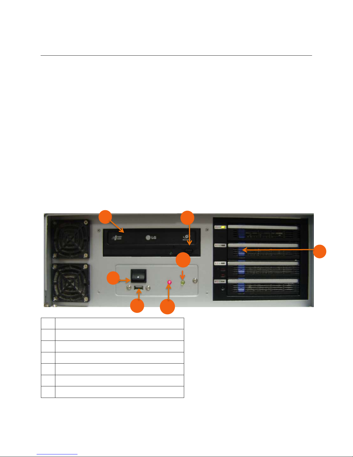
1.1 CONTROLS AND CONNECTIONS
1.
DVD-RW Drive
2.
DVD-RW Eject Tray Button
3.
Lock to Access Hard Drive(s)
4.
Hard Drive Activity LED Display
5.
Power LED Display
6.
USB Slot
7.
On/Off Power Switch
1
2
4
5
6
1.1.1 SYSTEM SPECIFICATIONS
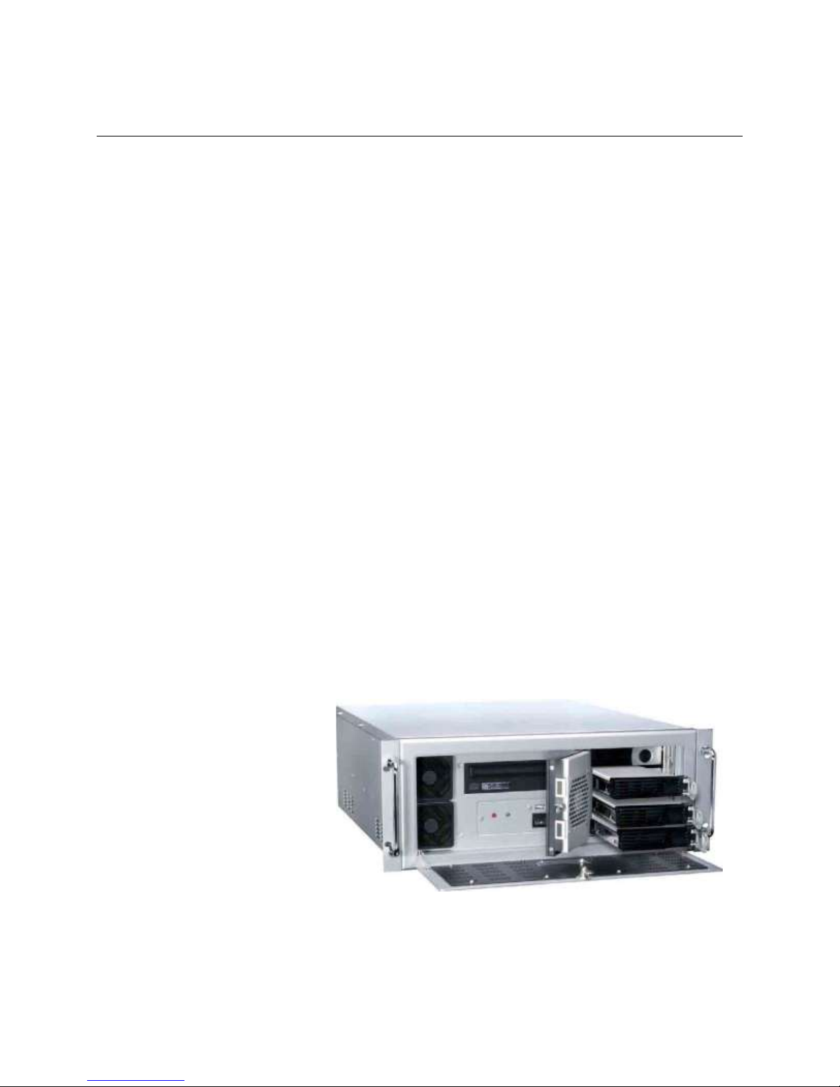
Digital Watchdog® state-of-the-art High Definition Network Video Recorders are housed in a high performance and versatile AU aluminum rack
mount case allowing easy storage of multiple NVRs for enterprise applications. Every Digital Watchdog NVR unit comes equipped with the
latest technology.
8CH- Intel® Intel i3 2120 3.3Ghz Quad Core
16CH- Intel® Intel i5 2400 3.4Ghz Quad Core
32CH- Intel® Intel i7 2600 3.8Ghz Quad Core
10/100/1000 Gigabit Network Card
4 GB of System Memory
1 MG Video Card
DVD-RW Recorder
Full Duplex High-fi Sound Functionality
500 GB ~ 20TB Video Storage Drive
1.1.2 FRONT PANEL CONTROLS AND LEDS
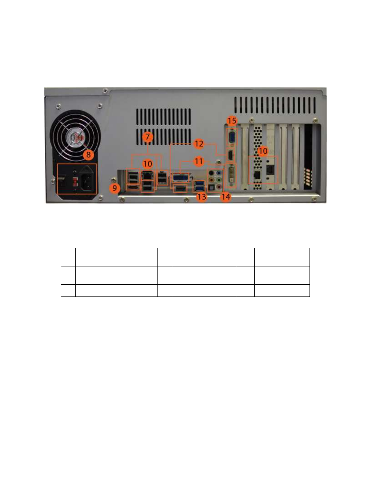
1.1.3 REAR PANEL CONNECTORS
7.
USB Ports 2.0
10.
RJ-45 Network Jack &
2nd Network Card
13.
USB Ports 3.0
8.
IEEE AC Power Connector &
110V/ 220V Switch
11.
USB DVI-I & DVI-D Outputs
14.
Audio In/ Out
9.
E-SATA Port
12.
HDMI Outputs
15.
VGA Output
Nexus Manual 022012 | 11
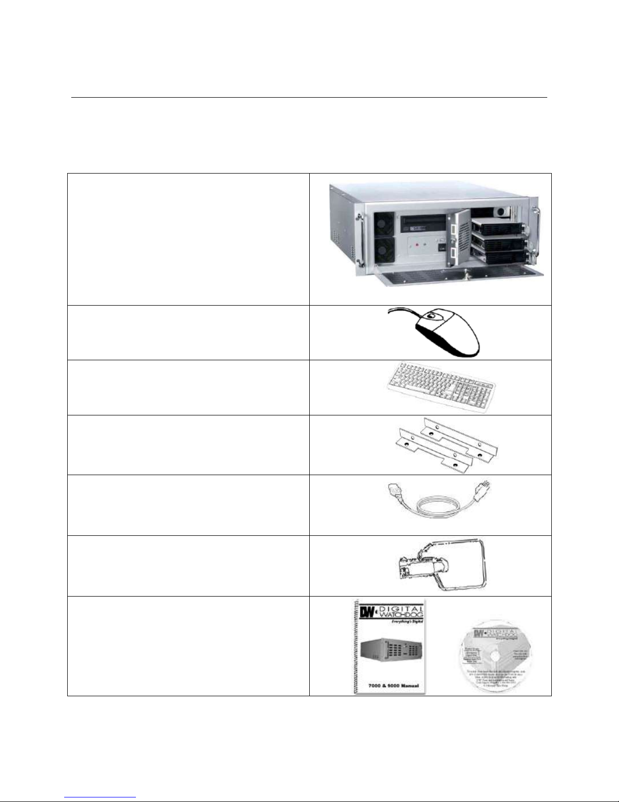
1.2 COMPONENTS
NVR Unit
Mouse
Keyboard
Rack Mount Attachments with Screws
Power Adapter
NVR Key
User Manual + NVR Repair Disc +
NVR Software Disc
1.2.1 INCLUDED HARDWARE
Digital Watchdog® NVRs come with a mouse, keyboard, and select software and cables. Identify the following components to make sure
everything has been included with your new NVR unit. If any of the following items are missing, contact your dealer to arrange a replacement.

1.2.2 KEYBOARD SETUP
To attach the keyboard to the NVR unit, plug the end of the keyboard into one of the available USB ports in the back of the NVR. Refer to the
Rear Panel Connectors image for more information.
1.2.3 MOUSE SETUP
To attach the mouse to the NVR unit, plug the end of the mouse into one of the available USB ports in the back of the NVR. Refer to the Rear
Panel Connectors image for more information.
1.2.4 MONITOR SETUP
You can connect a monitor to the NVR using the HDMI or the DVI-I output. Attach the monitors to the back of the NVR unit using the cables
supplied by the monitor manufacturer. Refer to your monitor manual for detailed information on how to setup and use it.
Note: The monitor must be capable of having a screen resolution of 1024 x 768 and display colors of at least 32 bits.
Nexus Manual 022012 | 13
1.3 SETTING THE DATE AND TIME
1. Exit to Windows by clicking the red X button on the Display Screen. Select Restart in Windows Mode. (See the Screen Display and Live
Options section.)
2. Double-click on the clock display (located on the bottom right corner of the screen).
3. Setup the time zone and adjust the date and time.
4. Click Apply. Click OK.
5. Close all open windows. Go to Start and select Restart to reboot the NVR.
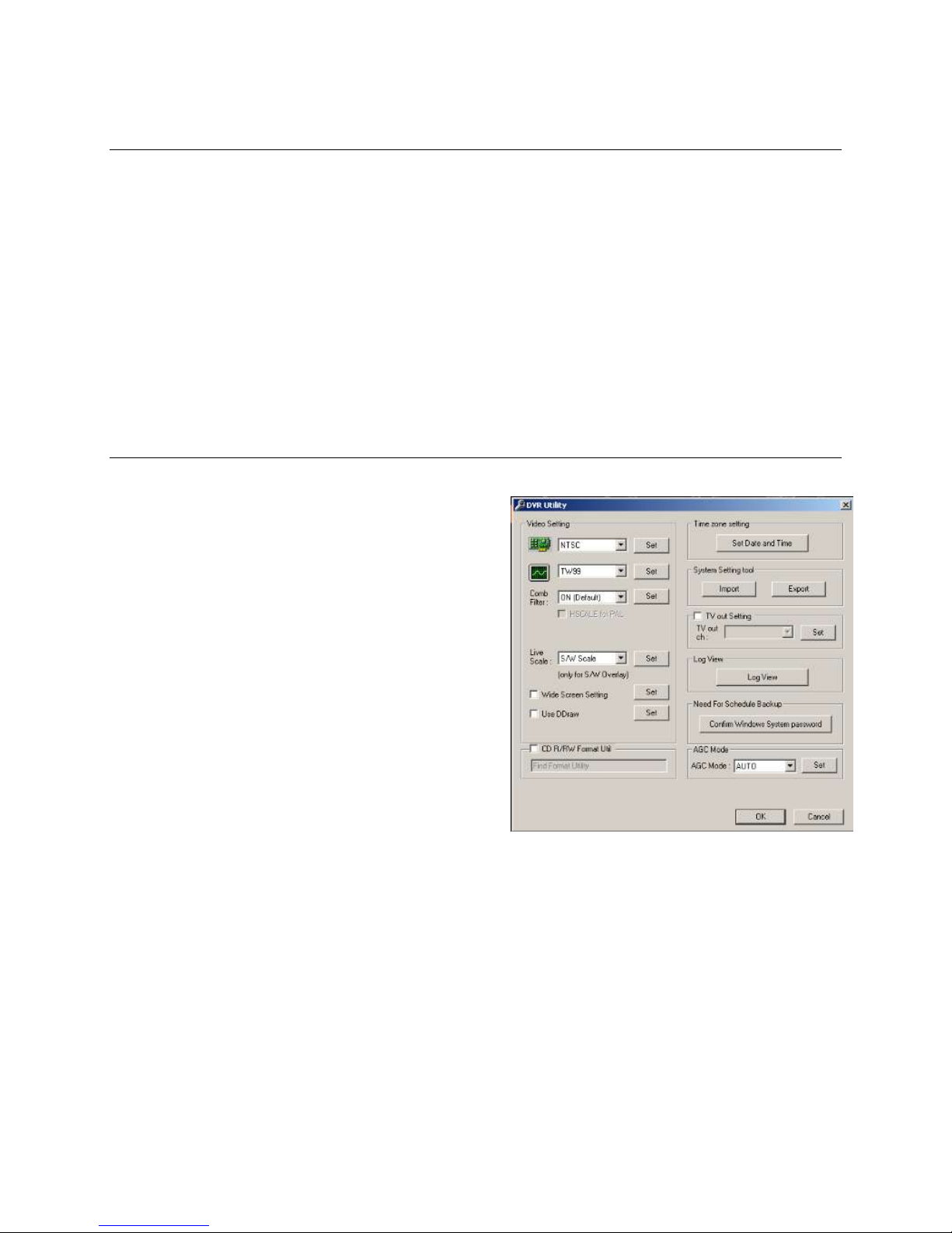
1.4 ACCESSING THE NVR UTILITY
Export settings can help configure multiple NVRs quickly or reconfigure a
unit that has failed. Some things must be kept in mind when using this
feature.
You can use the VFormat tool to update the time zone and select the TV
out settings (16/32 Channels, enable/disable AGC mode, and log view).
You cannot use this function:
On NVRs that are different models.
When upgrading the software versions. (This feature cannot
be used when upgrading from v2.x to v3.x.)
1.4.1 EXPORTING SETTINGS
1. Exit to Windows by clicking the red Exit button on the Display Screen.
Select Restart in Windows Mode. (See the Screen Display and Live
Options section.)
2. Click Start > Programs > Digital Watchdog > VFormat.
3. Click Export in the System Settings Tool section.
4. Select a location to save the settings file and click Save. The DVR settings will automatically be exported.
5. Click the OK button to close the VFormat Utility.

1.4.2 IMPORTING SETTINGS
1. Exit to Windows by clicking the red Exit button on the Display Screen. Select Restart in Windows Mode. (See the Screen Display and Live
Options section.)
2. Click Start > Programs > Digital Watchdog > VFormat.
3. Click the Import button in the System Settings Tool section.
4. Select the location of the settings file to import and click Open.
5. Click Yes to import the data file.
6. Select the OK button to close the VFormat Utility.
1.4.3 CHANGING VIDEO SETTINGS
1. Exit to Windows by clicking the red Exit button on the Display Screen. Select Restart in Windows Mode. (See the Screen Display and Live
Options section.)
2. Click Start > Programs > Digital Watchdog > VFormat.
3. In the Video Setting section, select the appropriate video setting from the list: NTSC or PAL.
4. Click Set.
5. Select the OK button to close the VFormat Utility.
1.4.4 SETTING THE NVR IP ADDRESS
1. Exit to Windows by clicking the red Exit button on the Display Screen. Select Restart in Windows Mode. (See the Screen Display and Live
Options section.)
2. Right-click My Network Places and click Properties.
3. On the General tab, click Internet Protocol (TCP/IP) and then click Properties.
4. Select Use the Following IP address.
5. Enter the following values (or as specified by the department responsible for network administration). a. IP Address: The first three sets of
numbers should match the router’s local IP address and the last set should be a unique number between 1-254. b. Subnet Mask: This
should match the router’s setting. The common subnet mask is 255.255.255.0 for 192.X addresses and 255.0.0.0 for 10.X addresses. c.
Default Gateway: This is the router’s internal IP address. Once the DDNS is configured, the router the NVR connects to will need to be
configured to forward ports 80 and 4000 to the IP address of the NVR.
For further instruction on this process, visit http://www.portforward.com/english/routers/port_forwarding/routerindex.htm.
Select the correct model of your router and follow the instructions. Once the DDNS and port forwarding have been configured, the NVR will be
accessible from any remote site by entering the HOSTNAME into the address bar of Internet Explorer or the IP Address field in the Remote
Software.
Nexus Manual 022012 | 15
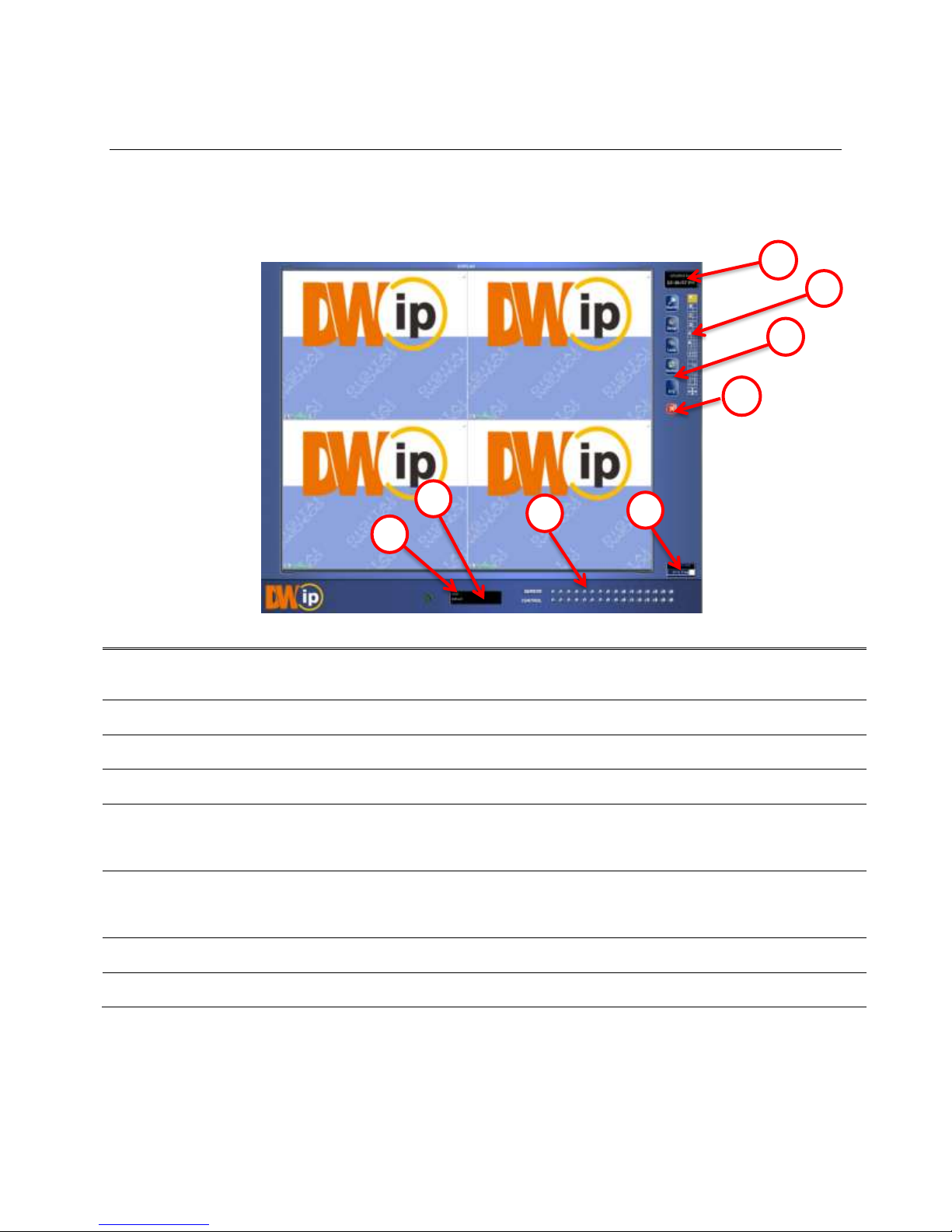
1.5 SCREEN DISPLAY AND LIVE OPTIONS
1.
Date / Time
Displays current date and time. This info is stamped onto the recorded video and is displayed whenever
the video is played back.
2.
Screen Division Buttons
View cameras in groups such as 2 x 2, 3 x 3, and 4 x 4
3.
Options Menu
4.
Exit
Exit software with one of the several options: Logout, Shut Down, Restart, and Restart in Windows Mode.
5.
Storage Capacity
Displays the total free space available in the NVR. When the storage capacity reaches 100%, NVR will
begin rewriting new data over the older recorded videos. The % number indicates how much free space is
available in the HDD.
6.
Sensor (Alarm Status Bar)
Relay
Displays the Alarm status for each sensor input.
Fires the Output relay. The output relays can be hooked up to external alarms, set to trigger a phone call,
etc.
7.
Current User
Displays the name of the user currently logged onto the NVR.
8.
Remote Client Status
Displays users remotely connected to the NVR.
1
2
3
4
5
6
8
7
Each time the NVR starts, the program defaults to the Display Screen. The following diagram outlines the buttons and features used on the
Display Screen. You should become familiar with these options, for this is the screen that will be displayed the majority of the time.
1.5.1 LOOP
Loop is an automated function that enables each Screen Division view to be seen consecutively on the Display Screen.
1. Go to the Display Screen.
2. Highlight the Loop button by selecting it with the mouse.
3. The Display Screen will automatically scroll through each Screen Division view consecutively.
4. To turn off this feature, un-highlight the Loop button by selecting it with the mouse.
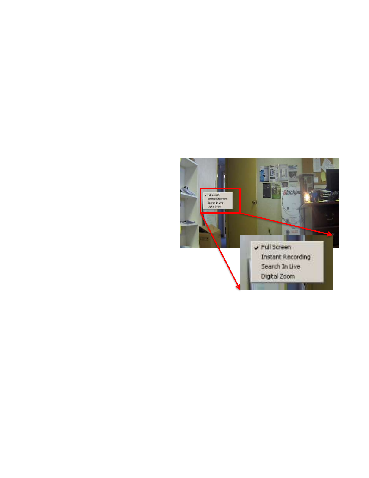
1.5.2 LIVE CAMERA OPTIONS
Select a camera on the display screen and right-click the mouse
button to display the following options:
Full Screen
Instant Recording
Search In Live
Digital Zoom (in Single Channel View Mode only)
1.5.3 LIVE DIGITAL ZOOM
Zoom in on an image while watching live video. This feature is available only in single channel view mode.
1. Select a camera. Double-click on image until it goes to single channel view mode.
2. Right-click on the screen. Select Digital Zoom.
3. Using the mouse’s wheel, scroll forward to zoom in or backwards to zoom out.
4. Select a Screen Division button to resume viewing multiple channels.
Nexus Manual 022012 | 17

1.5.4 INSTANT RECORDING
The Instant Recording feature allows users to initiate recording manually on a specific camera, overriding the current schedule. When Instant
Recording is activated, the NVR flags the clip as an event. Instant Recording instances can be found using the Index Search.
Instant Recording can be used when a suspicious object or person is detected and the user wants to flag that section of video for easy retrieval
in the future.
To activate Instant Recording:
1. Select a camera. Right-click on the screen and select Instant Recording.
2. To turn off the Instant Recording option, right-click on the screen and select Instant Recording again.
To Search Instant Recording:
1. From the Display Screen, click Search.
2. Select Index Search.
3. Select Instant Recording. See Chapter 3: Search Options for more information.
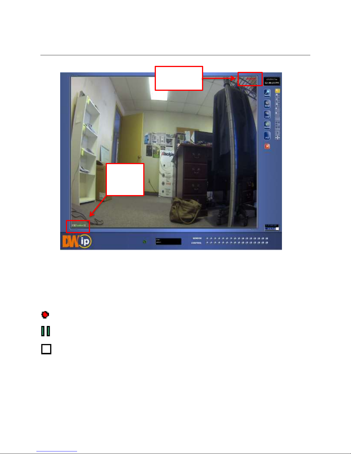
1.6 CAMERA VIEW
Recording
Status
Camera
Number
& Name
1.6.1 RECORDING STATUS INDICATOR
The camera status for each camera is displayed on the upper right corner of the video display area. The following are the different status for
each camera:
Recording Displayed when the camera is currently being recorded to the NVR.
Motion Detection Displayed when a camera that is set for motion detection detects motion.
Display Displayed when the camera is currently not being recorded to the NVR.
Nexus Manual 022012 | 19
1.6.2 SPECIAL RECORDING
There are two types of special recordings. When each of these is activated, a text will be displayed on the camera’s video to indicate what type
of special recording has been activated.
SENSOR Sensor is displayed when a sensor associated with the given camera is activated.
INSTANT Instant Recording manually activates recording for a selected camera. Regardless of the recording schedule, Instant Recording will
start the camera recording and flag the video for future searches in the Index Search feature.
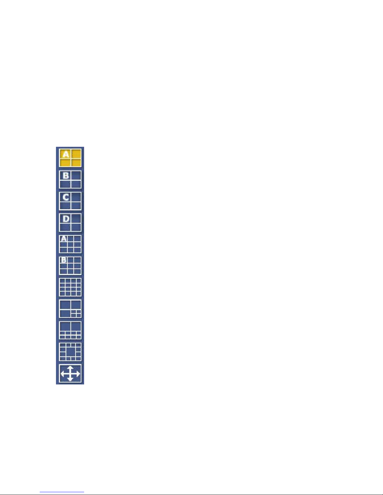
1.6.3 SCREEN DIVISION BUTTONS
•1ST Four Cameras View- Displays cameras 1-4 in the Video Display Area.
•2nd Four Cameras View- Displays cameras 5-8 in the Video Display Area.
•3rd Four Cameras View- Displays cameras 9-16 in the Video Display Area.
•4th Four Camera View- Displays cameras 13-16 in the Video Display Area.
•1st Nine Cameras View- Displays cameras 1-9 in the Video Display Area.
•2nd Nine Cameras View- Displays cameras 10-16 in the Video Display Area.
•All-Camera View- Displays all 16 cameras within the Video Display Area.
•Multi-Camera View- Displays a group of cameras within the Video Display Area.
•Multi-Camera View- Displays a group of cameras within the Video Display Area
•Multi-Camera View- Displays a group of cameras within the Video Display Area
•Full-Screen- View the Video Display Area using the entire viewable area on the monitor. When this is selected, no menu
options will be visible. To exit, simply press the Esc button on the keyboard.
Chapter 2: SETUP OPTIONS
OVERVIEW
The Setup options allow the user to optimize the NVR by adjusting options such as camera names, reboot schedules, recording schedules, and
more. It is extremely important that the NVR is set up correctly for several reasons.
Recording Schedules increase the amount of pertinent recorded video that is saved on the NVR by optimizing the recording schedule. Optimize
the type of recording done by adding motion detection to this as well, again increasing the amount of useful video.
Sensor connections define the sensors associated with each camera.
NVR Access controls the type of access that other users may have. This ensures the security and integrity of the NVR unit.
Camera Naming names each camera so the location can be easily identified and will include any other pertinent information that may be helpful
when viewing it on the Video Display Area.
SETUP SCREEN
Nexus Manual 022012 | 21

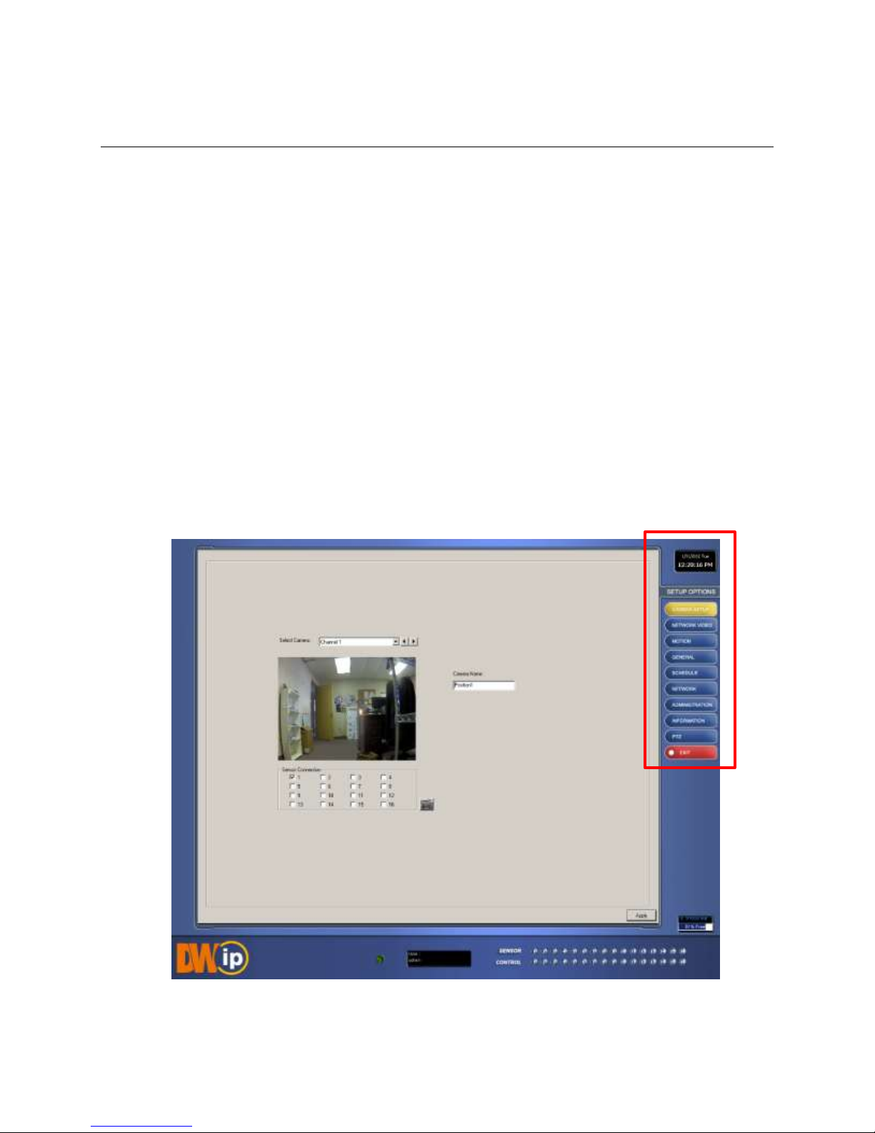
2.1 CAMERA SETUP
Use this Setup menu to adjust the camera’s name and assign a specific sensor.
2.2 NETWORK VIDEO
Digital Watchdog
Panasonic
ACTi
Piuxord
Arecont Vision
Samsung
Axis
Sony
D-Link
Toshiba
Lumenera
VivoTek
Mobotix
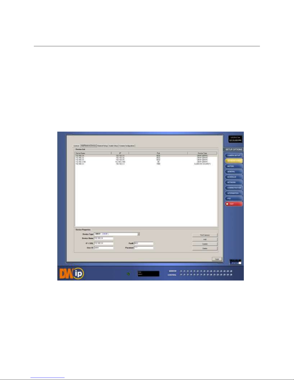
In the Network Setup menu, you can add/edit/delete IP cameras. You can manually enter each camera’s information or use the Find Cameras
tool. This feature will enable the NVR to search and register every camera connected to the same network.
The Nexus NVR supports most major IP camera brands, including:
Nexus Manual 022012 | 23
2.2.1 CONNECTING A NETWORK DEVICE MANUALLY
1. From the Display Screen, select Setup.
2. Click the Network Video tab.
3. Click the Add/Remove Device tab.
4. Select your network device from the Device Type list.
5. Under Device Properties, type a Device Name.
6. Type the IP/URL address, Port, User ID and Password of the device.
7. Click Add.
2.2.2 CONNECTING A NETWORK DEVICE USING CAMERA FINDER
1. From the Display Screen, select Setup.
2. Click the Network Video tab.
3. Click the Add/Remove Device tab.
4. Click Find Cameras to locate all connected Network cameras automatically.
5. Select the check box next to the desired camera.
6. Click Get Device.
7. Type the User ID and Password of the device.
8. Click Update.
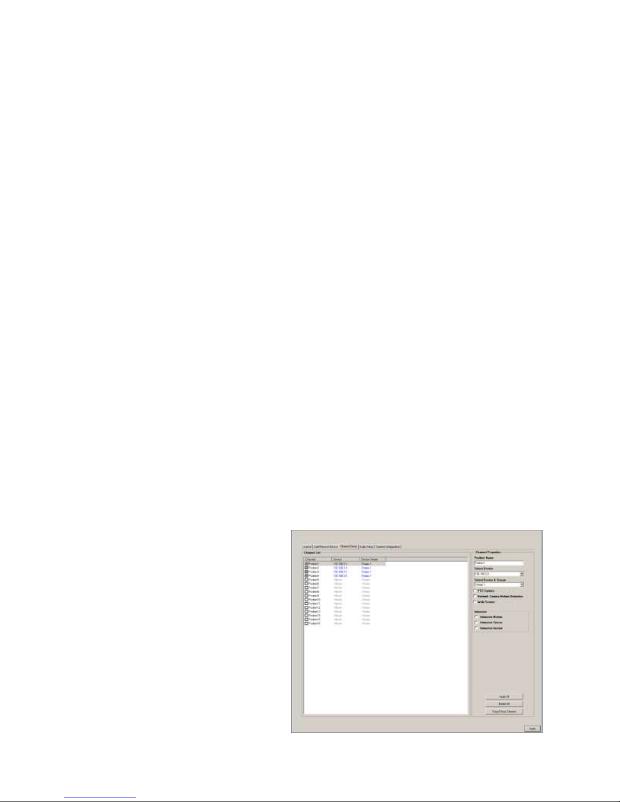
2.2.3 ASSIGNING A NETWORK DEVICE TO A CHANNEL
1. From the Display Screen, select Setup.
2. Click Network Video.
3. Click the Channel Setup tab.
4. Select an available channel on the Channel
List.
5. Type the desired Position Name.
6. From the Select Device list, select the
appropriate network device added previously.
7. If the device has PTZ capabilities, select the
PTZ Camera checkbox to enable.
8. If supported, select the Use Network Camera Motion Detection checkbox.
9. Select Intensive Motion, Intensive Sensor, and/or Intensive Instant to increase the recording rate on an event.
10. Click Apply.
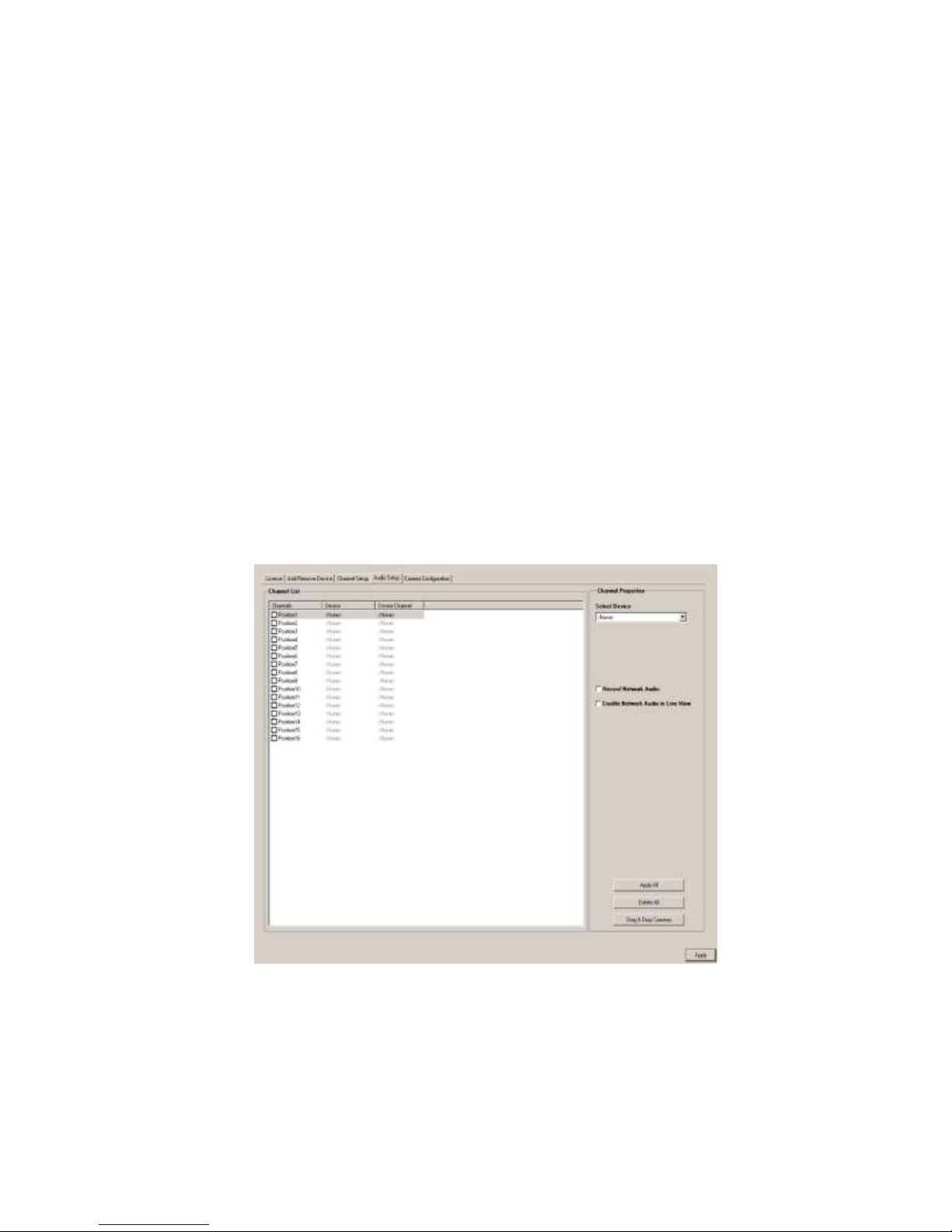
2.2.4 ASSIGNING AUDIO CHANNELS TO A NETWORK DEVICE
1. From the Display Screen, select Setup.
2. Click Network Video.
3. Select the Audio Setup tab.
4. Click an available audio channel on the Channel List.
5. From Select Device list, select a network device added previously.
6. To record the network audio, select the Record Network Audio checkbox. The audio channel will be available on the search
screen.
7. To access the audio channel from the Live View screen, select the Enable Network Audio in Live View checkbox.
Nexus Manual 022012 | 25
 Loading...