

Page 1

WHAT’S IN THE BOX
Quick star t guide &
Download guide
1 Set
Template sheet 1 Set
Torx wre nch 1 Set
Waterproof cap & Ga sket 1 Set
Moisture abso rber – 2pcs
& Absorber guide
1 Set
Test video cable 1 Set
Screw & Plastic a nchor – 4pcs 1 Set
STEP 1 – PREPARING TO MOUNT THE CAMERA
STEP 3 – INSTALLING THE CAMERA
STEP 2 – CABLING THE CAMERA TO EXTERNAL
DEVIC ES
1. The mounting sur face must bear ve times the wei ght of your camera.
2. Do not let the cables get caught in improper places or the electric line
cover to be damaged. Th is may cause a breakdown or re.
3. For the installation process, rem ove the dome cover from the camera
module by loosen ing the screw on the side of the dome. Use the
wrench provided w ith the camera.
4. Remove the protective foam from the cam era.
5. A ssemble the Sensor Module B lock (with a lens) at the Base Guide.
a. To operate a camera functio ns working properly, the Sensor Mo dule
Block must be ass embled the Base Guide up to four of the B ase
Guide points.
b. Ple ase make sure to t together Sensor Mod ule Block and Base
Guide in accorda nce with the gure below. Unless you fol low the
instructions, the assembly is impossible.
c. Opposite ways asse mbling is impossible due to inter face sockets
locations.
6. Us ing the mounting template sheet or th e camera itself, mark and drill
the necessar y holes in the wall or ceiling.
9. Once all cables are conne cted, secure the camera to the mounti ng
surface using the included screws.
10. Adjust the camera module on the magnetic surface for the ultimate
coverage and view. Each c amera module snaps into positi on using
the magnetic track, allowing for maximum customization and fully
adjustable views. Please refer to the user manual for additional
information on positioning recommendations.
11. Install the moist ure absorber according to the gu ide included. Remove
the dome cover’s inner protec tive lm. Re-attach the camera’s dome
to the camera modul e by aligning the screw holes. Remove t he dome
cover’s outer protective lm to com plete the installation.
DWC- PVX16W
7. Pass the wires through the mount b racket and make all necessar y
connections.
a. NETWORK CO NNECTIONS – Using a PoE Switch or PoE Inje ctor,
connect the camera using an Ethernet cable for both data and
pow er.
b. NET WORK CONNECTIONS – Not using PoE Switch or PoE Injector,
connect the camera to the switch using an Ethernet cable for data
transmission a nd use a power adapter to power the camera .
POWER
NETWORK
10
1
2
3
4
7
11
11
11
6
Template
Sheet
Remove the outer protection
lm from the camer a’s dome
to complete the installation
Remove the
dome cover inner
protection lm
Base Guide
Sensor Module
Block
Power Requirement s Power Consumption
DC12V, PoE+ IEEE 802.3at class 4
(High Power POE injector included)
18W
NOTE: Downloa d All Your Support Mater ials and Tools in One Place
1. Go to: http://www.digital-watchdog.com/support-download/
2. Search your pro duct by entering the pa rt number in the ‘Search by Product’
search bar. Results for applicable part numbers will populate automatically
based on the par t number you enter.
3. Click ‘Search’. All supporte d materials, includ ing manuals, Quic k Start
Guides (QSG), sof tware and rmware wi ll appear in the resu lts.
Tel: +1 (866) 446-3595 / (813) 888-9555
Technical Support Hours: 9:00AM – 8:00PM EST,
Monday thru Friday
digital-watchdog.com
Attention: T his document is inten ded to serve as a quic k reference for init ial
set-up. It is rec ommended that the u ser read the entire i nstruction man ual
for complete and proper installation and usage.
Quick Start Guide
Quick Start Guide
Default Login Information
Username: admin Password: admin
a
b
c
8
8. To use the camera’s water proof wir ing:
(1). Install the LA N cable into .
(2). will be assemb led to with a 1/4 turn.
(3). Thread tightly to .
a
a
b
b
c
NOTE: To ensure moisture s eal, make sure the o-ring is in place
between and . In ex treme environments use of an
outdoor rated sealer is recommended.
a
b
NOTE: When using the waterproof cap, crimp the RJ45 connector
after passing th e cable through the waterproof cap.
Test Monitor
Select Switch
Reset Button
Resetting the camera: To reset the camera, use the tip of a p aper
clip or a pencil an d press the reset button. Pressin g the button for
ve (5) seconds will i nitiate a camera-wide reset of all the s ettings,
including network settings.
5
Page 2
Quick Start Guide
STEP 4 – CABLING
Use the diagram below to properly connect power, network, audio, alarm
and sensors to the ca mera.
Using a PoE-Enabled Switch Using a Non-PoE Swi tch
Power
Ethernet cable
Ethernet cable
Alarm In
Alarm Out
Audio Out
DI (+)
DI (–)
DO (–)
DO (+)
WHITE
YELLOW
SKY BLUE
PURPLE
Audio In
OPTIONAL:
STEP 5 – MANAGING OPTIONAL SD CARDS
To install the memory ca rd:
1. Detach the camer a’s cover dome from the c amera’s module by
unscrewing the cove r dome screws.
2. Inse rt a Micro SD/SDHC Class 10 card accordi ng to the diagram.
3. To remove the SD ca rd, press the card gently into the card s lot to
release it. The ca rd will pop out automatically.
SD Card Slot
SD Card Slot
SD Card Slot
SD Card Slot
NOTE: The cam era has up to 4 SD card slots. Please refer to th e
diagram below for position.
NOTE: For security purposes, it is highly recommended to change
the cameras default password.
7. To view the camera’s web viewer, click on ‘View C amera Website’.
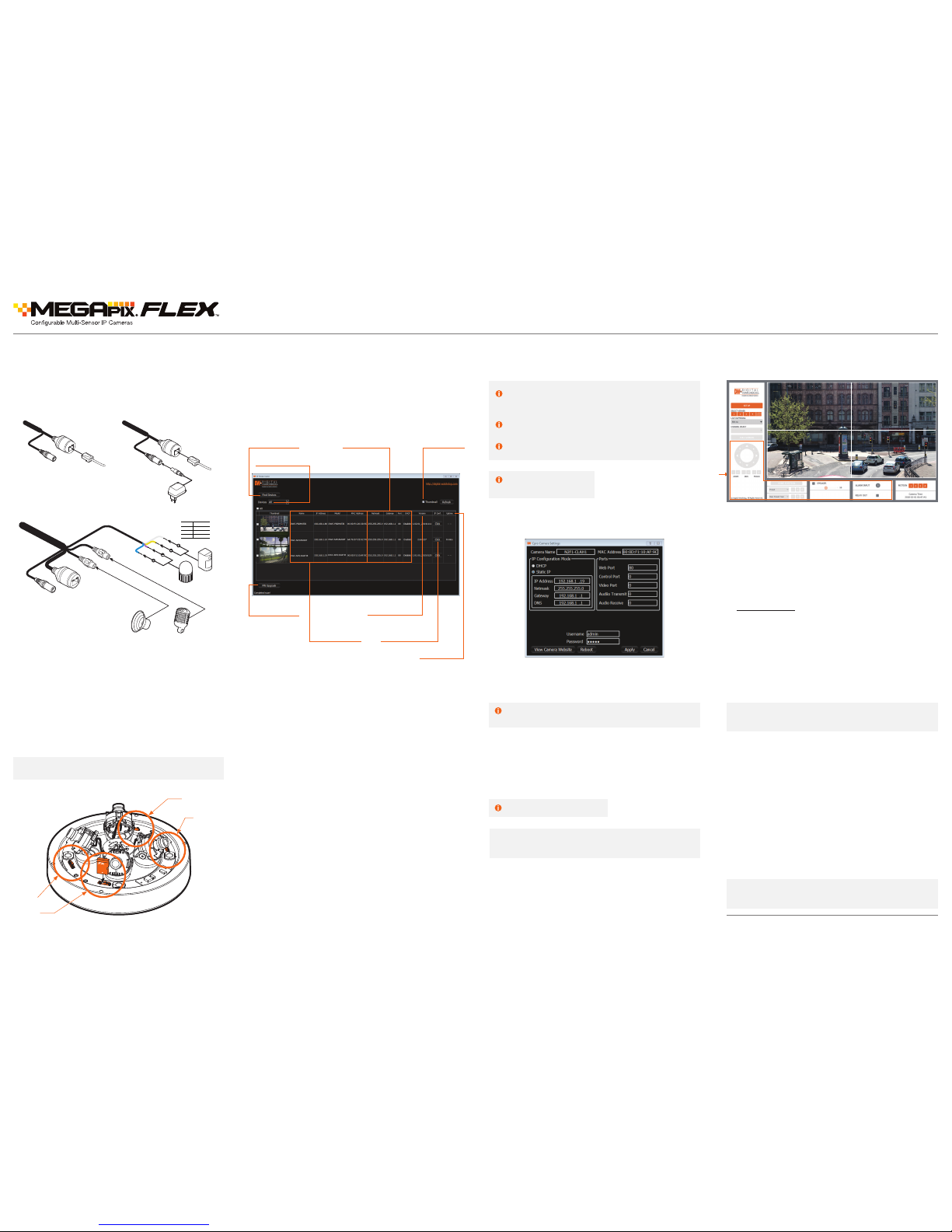
Use the DW IP Finder
™
software to scan th e network and detect all
MEGApix® cameras, set the ca mera’s network settings or acces s the
camera’s web client.
‘Port Forwardi ng’ has to be set in your network’s router for
external acce ss to the camera.
Network Setup
1. Go to: http://www.digital-watchdog.com
2. Sea rch for ‘IP Finder’ on the quick sear ch bar at the top of the page.
3. The l atest IP Finder software will a ppear in the search results. C lick on
the link to download the le to your computer.
4. Lau nch the DW IP Finder software by do uble-clicking on the
downloaded le.
5. The s oftware will scan your netw ork for all supported came ras and
display the result s in the table. Allow up to 5 seconds for the I P Finder
to nd the camera on the n etwork.
6. Sel ect a camera from the list by doubl e-clicking on the camera’s
image or clicki ng on the ‘Click’ button under the IP C onf. column. The
camera’s network infor mation will appear. If necessar y, you can adjust
the camera’s network ty pe.
Search for Cameras
Cam era’s
Network Settings
Vie w Came ra’s
Thumbnail View
Cam era’s Firmware
Camera Uptime
Open Camera’s IP
Conguration Screen
Filter Search Results
Camera Name,
Model, IP Address,
and MAC Address
Firmware Upgrade
NOTE: Please s ee the full product manua l for web viewer setup,
functions and camera settings options.
Rev Date: 04/18
Copyright © Di gital Watchdog. All r ights reserve d.
Specications and pricing are subject to change without notice.
8. To save the chang es made to the camera’s settings, input the ID a nd
PW of the camera for au thentication and click ‘Save’.
9. If the c amera needs to be rebooted after th e settings were changed,
press the ‘Reboot’ b utton. The camera will cycle powe r and will appear
back in the search re sults once the reboot is complete.
Default ID / PW : admin / adm in
NOTE: Some Me nu options may not be available b ased on the camera
model. See the full manual for more information.
*
Once the camera’s networ k settings have been setup prope rly, you can
access the came ra’s web viewer using the DW IP Finder™ (see step 7
under STEP 6 IP Finde r™), or directly via a supp orted web browser.
To open the camera’s web viewer:
1. Open a supported web browser (Internet Explorer
®
8.0 or above).
2. Enter th e camera’s IP address and port in the add ress bar. Example:
http://ipaddress/port.
Please note that por t forwarding may be necess ary in order to access
the camera from a di fferent network. Please c ontact your network
administrator for additional information.
3. Enter th e camera’s username and password (defau lt are admin /
admin).
4. If you are a ccessing the camera for the rst time, install the ActiveX for
web les in order to vie w video from the camera.
STEP 6 – DW IP FINDER
™
STEP 7 – WEB VIEWER
The GUI display m ay differ by camera mo dels.
Default TCP/IP information
• IP: DHCP
Select DHCP if the I nternet service is dynam ic IP. This will
allow the camera to re ceive its IP address from the DHCP
server.
Select STATIC to manually enter the c amera’s IP address,
subnet mask, Gateway a nd DNS information.
Contact your network administrator for more information.
*
 Loading...