

Digital Watchdog MEGApix CaaS DWCA-VF25W28-64, MEGApix CaaS DWCA-VF25WIR4-64, MEGApix CaaS DWCA-VF25WIR8-64, DWCA-C128-64, DWCA-C12C-64 User Manual
Page 1
DWCA-VF25W28-64
DWCA-VF25WIR4-64
DWCA-VF25WIR8-64
MEGApix CaaS™ Surface Mount Outdoor Dome Camera
Before installing or operating the camera, please read and follow this manual carefully.
REV.0715
Page 2

PRECAUTIONS
Do not open or modify.
Do not open the case except during maintenance and installation, for it may be dangerous and can cause
damages.
Do not put objects into the unit.
Keep metal objects and flammable substances from entering the camera. It can cause fire, short-circuits, or
other damages.
Be careful when handling the unit.
To prevent damages, do not drop the camera or subject it to shock or vibration.
Do not install near electric or magnetic fields.
Protect the camera from humidity and dust.
Protect the camera from high temperature.
Be careful when installing near the ceiling of a kitchen or a boiler room, as the temperature may rise to high
levels.
Cleaning: To remove dirt from the case, moisten a soft cloth with a soft detergent solution and wipe.
Mounting Surface: The material of the mounting surface must be strong enough to support the camera.
FCC COMPLIANCE
This equipment has been tested and found to comply with the limits for a Class B digital device, pursuant to Part 15 of
the FCC rules. These limits are designed to provide reasonable protection against harmful interference, when the
equipment is operated in a residential environment. This equipment generates, uses, and radiates radio frequency
energy, and if it is not installed and used in accordance with the instruction manual, it may cause harmful interference
to radio communications.
WARNING: Changes or modifications are not expressly approved by the manufacturer.
2
Page 3

TABLE OF CONTENTS*
Introduction.......................................................................................................................................................4
Features........................................................................................................................................................4
Parts .............................................................................................................................................................5
Dimensions...................................................................................................................................................6
Inside the Box ..............................................................................................................................................7
Installation.........................................................................................................................................................8
Network Connection ....................................................................................................................................8
Installation- Easy Camera Installation ........................................................................................................9
Installation- Adjusting the Camera’s Lens ..................................................................................................9
Installation- Using the Mount Plate ...........................................................................................................10
Installation- Using the Bolts & Nuts ..........................................................................................................11
Installation- SD Card .................................................................................................................................12
MEGApix® CaaS™ Camera Setup................................................................................................................13
Installing DW IP Finder™ ..........................................................................................................................13
Using DW IP Finder™ ..........................................................................................................................14-15
Network Options.........................................................................................................................................16
Camera Reboot..........................................................................................................................................17
MEGApix® CaaS™ Camera Web Viewer.....................................................................................................18
Accessing the Camera’s Web Viewer.......................................................................................................18
GUI Description .........................................................................................................................................19
First & Second Stream...............................................................................................................................20
Export & Print Image.................................................................................................................................21
Instant Recording.......................................................................................................................................22
Audio Control.............................................................................................................................................23
Alarm & Relay Control ..............................................................................................................................24
MEGApix® CaaS™ Camera Setup...............................................................................................................25
Basic ....................................................................................................................................................25-28
DW Spectrum CaaS™..........................................................................................................................28-30
Camera..................................................................................................................................................21-33
System..................................................................................................................................................34-38
Specifications ...........................................................................................................................................39-40
Troubleshooting .......................................................................................................................................41-44
Warranty..........................................................................................................................................................45
Limits & Exclusions.......................................................................................................................................46
3
Page 4

FEATURES*
1/3" 3.0 Megapixel CMOS Image Sensor ( 3.0MP, 30fps)
Digital Wide Dynamic Range (DWDR)
DW Spectrum™ VMS Edge Storage and Managemen t
Run DW Spectrum Edge Simultaneously with additiona l analyt ics software
8.0mm, 2.8mm and 4.0mm Lens Options
Web Server Built-in
Smart DNR™ 3D Digital Noise Reduction
Network Failover and Redund an cy
SD/SDHC Card Slots (up to 128GB)
64GB SD Card Class 10 included
True Day/Night with Mechanical IR Cut Filter
Auto Gain Control (AGC)
Backlight Compensatio n (BLC)
Auto White Balance (AWB)
Motion Detection
Power over Ethernet (PoE) & DC12V
ONVIF Compliant, Profile S
Compact Size for Disc r ete Ins tal l ati o ns
Dual Codecs (H.264, MJPE G) with Simultaneou s Mult i-Stream
IP66 Certified (Weather Resis tant)
4
Page 5
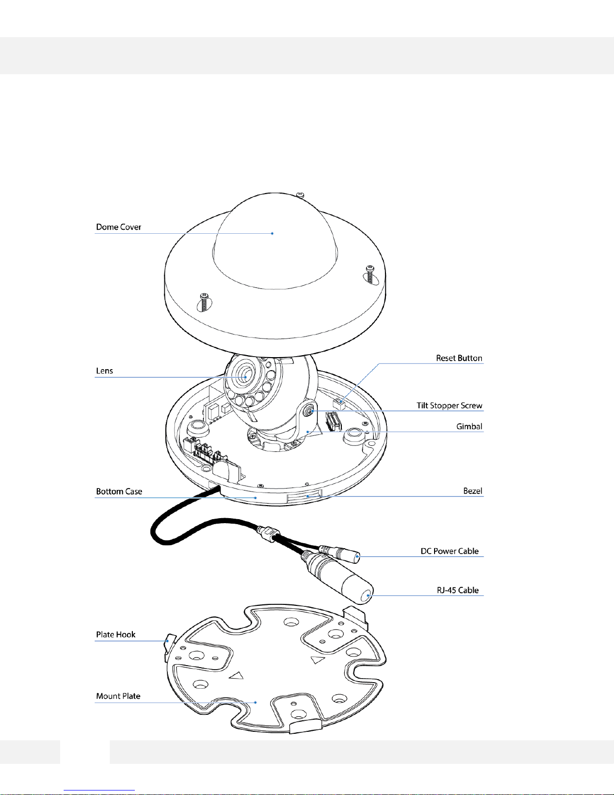
PARTS & DESCRIPTIONS*
5
Page 6
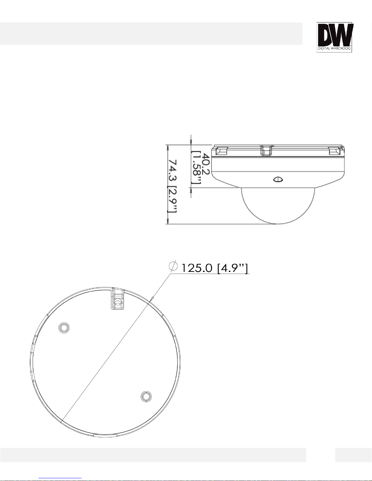
DIMENSIONS*
6
Page 7
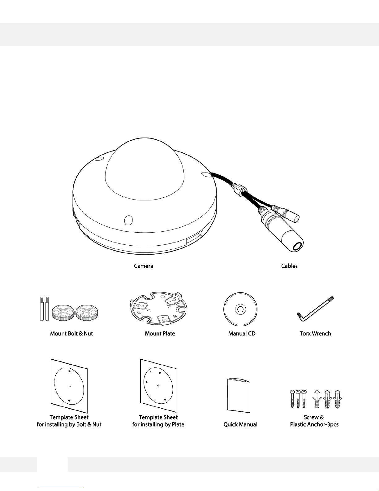
INSIDE THE BOX *
The following items are included w i th the MEGApix® CaaS™ camera.
7
Page 8
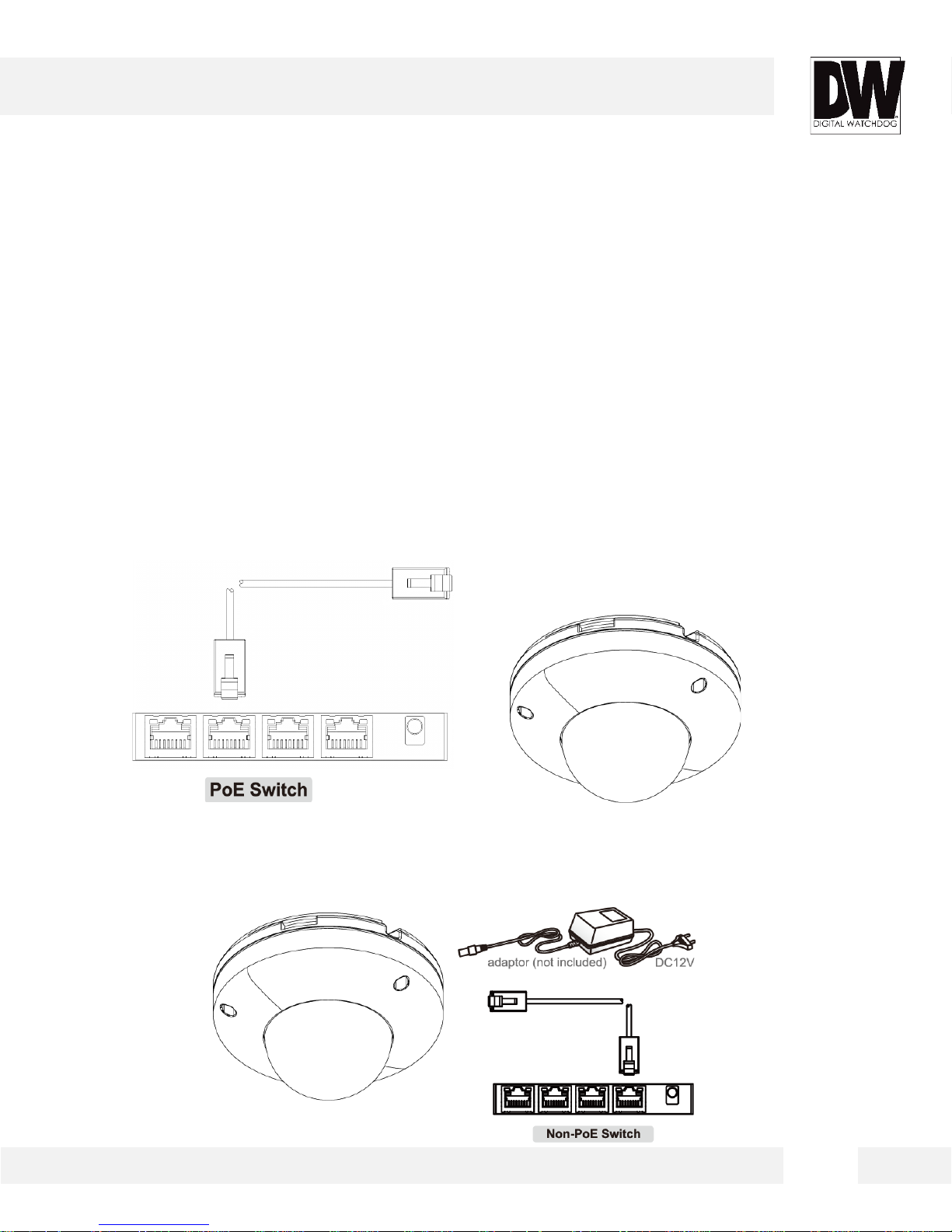
NETWORK CONNECTION*
There are two way to power a MEGApix® CaaS™ camera.
Use a PoE- enabled switch to connect data and power through a single
cable and begin viewing and recording images instantly. A non- PoE
switch will require an adaptor for power transmission.
1. Using a PoE-Enabled Switch
The MEGApix® CaaS™ Camera is PoE-Compliant, al lowi ng transmission of power and data via
a single Ethernet cable. PoE elimi nates t he need for the differ ent cables used to power, record,
or control the camera. Follow the illust ration below to connect the camera to a PoE-enabled
switch using an Ethernet cable.
2. Using 12VDC
If a PoE injector is not avail abl e, use a power adaptor for power transmissi on and a non-PoE
switch for data transmiss ion. Follow the il l ustr at ions below to connect the c amera without a PoE
Injector.
8
Page 9
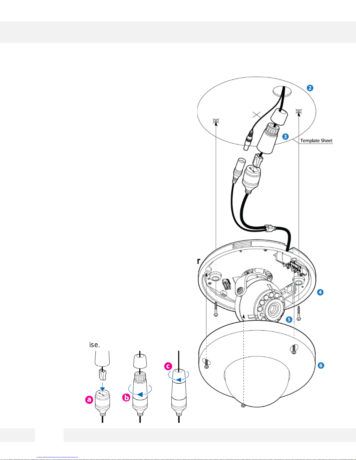
INSTALLATION*
Easy Camera Installation
1. Detach the camera’ s c over dome from the
camera’s module by unscrew ing the three cover
dome screws using the L-Wrench.
2. Use the camera or mounting template to mark and
drill the necessary hol es i n the wall or ceiling.
3. Pull wires through and make connecti ons.
4. Using three (3) included screws, mount and secure
the camera to the wall or ceiling.
5. Secure the camera’ s c over dome onto the camera
base to complete t he ins tal l ati on .
Using the Cable Weather Protector
To use t he LAN water protector case, refer t o the
diagram below:
1. Insert the network cabl e i nto ( a) , the camera’s
network port.
2. Connect (b) to the camera’s network por t by
rotating it clock-wise until tight.
3. To complete the water-proof install ation, connec t
part (c) to the case’s body, securing tightly by
rotating it clock-wise.
9
Page 10
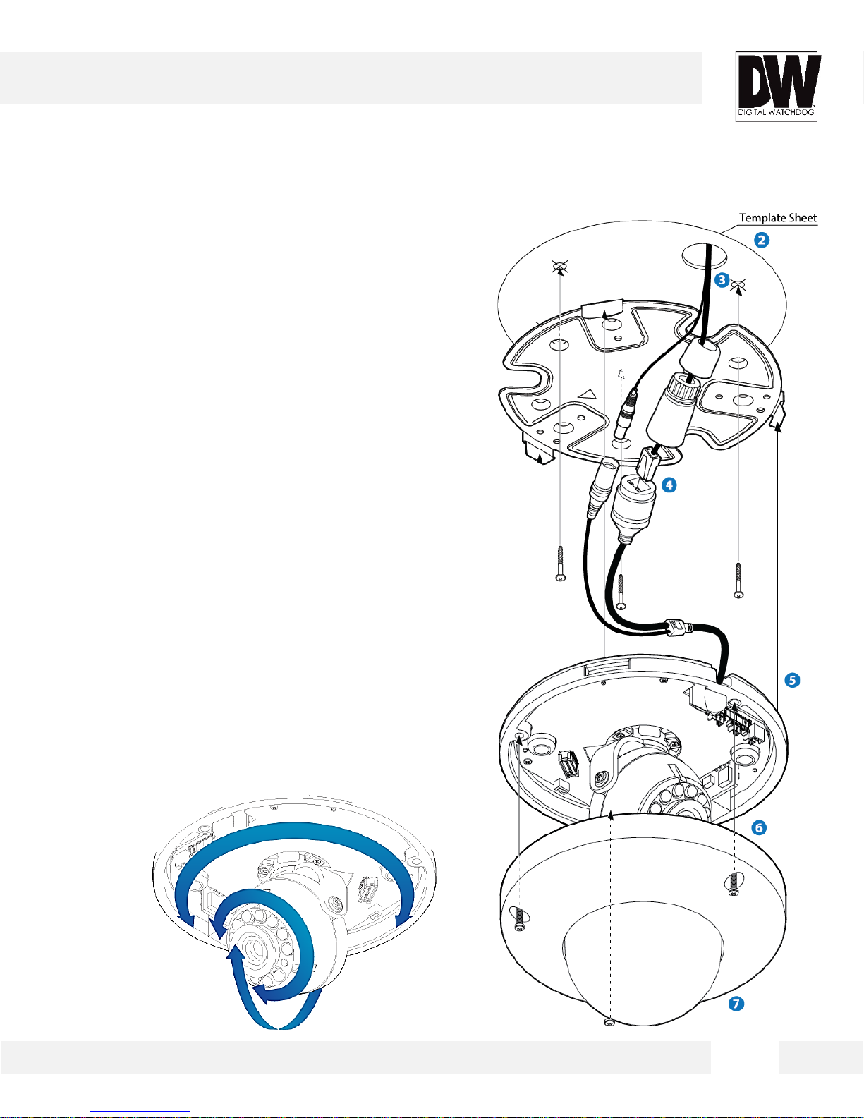
INSTALLATION USING MOUNT PLATE*
1. Detach the camera’ s c over dome from the camera’s
module by unscrewing the three cover dome screws.
2. Using the metal mount plate, mark and drill the
necessary holes i n the wall or ceiling.
3. Pull wires through and make connecti ons.
4. Using the three (3) included screws, mount and secure
the camera to the wall or ceiling.
5. Attach the camera base to the metal mount by
snapping it into place using the two metal handles.
6. Secure the camera’ s c over dome onto the camera
base to complete t he ins tal l ati on .
7. See page 9 for water-proof cabling install ation.
Adjusting the Camera’s Angle
To adjust the camera’s orientati o n:
1. 1. Loosen the tilt stopper screw at the base of the
camera’s Gimbal by rotating it counter clock-wise.
2. 2. Move the camera to the desired angle.
3. 3. Secure the camera’ s lens position by screwing
the tilt stopper screw clock-wise.
10
Page 11
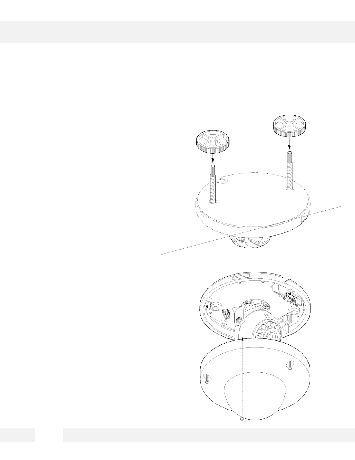
INSTALLATION USING MOUNT BOLT & NUT*
1. Detach the camera’ s c over dome from
the camera’s module by unscrewing
the three cover dome screws.
2. Using the camera or mounting
template, mark and drill the necessary
holes in the wall or ceiling.
3. Secure the two long mounting scr ew s
to the camera’s bas e.
4. Pull wires through and make
connections.
5. Mount the camera to the mounting
surface using the 2 mounting nuts.
6. Secure the camera’ s c over dome onto
the camera base to complete the
installation.
7. See page 9 for water-proof cabling
installation.
8. See page 10 for adjusting the camera’ s
tilt and angle.
11
Page 12
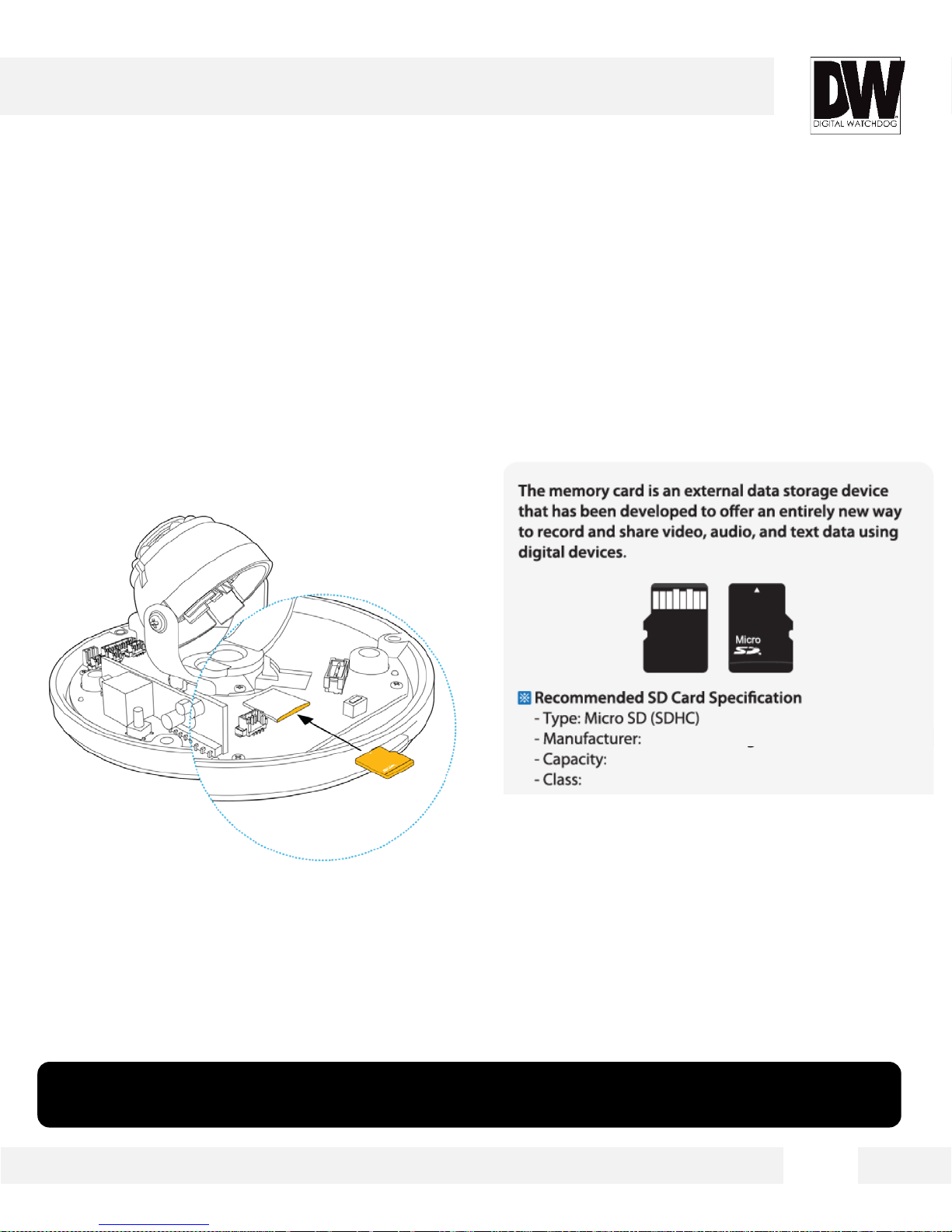
INSTALLATION*
SD Card
The MEGApix® CaaS™ camera can record locally,
eliminating the need for dedicated drivers.
1. To install the camera’s SD Card, locate the SD card slot in the back of the camera module.
2. Insert a class 10 SD card into t he SD card sl ot by pressing the SD card slot.
3. To remove the SD Card, press the c ar d inward to
release from the c ar d sl ot.
SanDisk
16~128GB
Over Class 10
*NOTE: 64GB SD Card Class 10 is already included with your camera. To upgrade the card, please
follow the instructions above.
12
Page 13
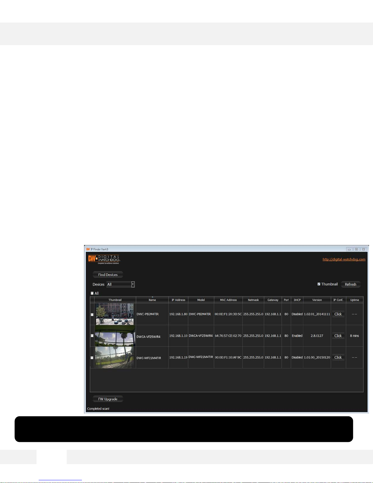
DW IP FINDER™ *
Installing DW IP Finder™ Software
DW IP Finder™ searches for all available Digital Watchdog devices
currently connected to your network.
1. Install DW Desktop Tool to find the MEGApix® CaaS™ camera on your local network. The
software can be found on the included User Manual CD. Run DW Desktop Tool and install
onto your PC.
2. When setup is complete, launch DW Desktop Tool.
3. The software will automatical ly searc h your network for all Digi tal Watch do g ® suppor ted
devices. Your camera will appear, for ex ample, as ” DWCA-VF25WIR4.”
4. Double-click on the camera name and select ‘View Camera Website’ to launch the camera’
web viewer.
*Install the DW IP Finder to a computer located on the same Subnet Mask as the MEGApix® CaaS™
camera.
13
Page 14
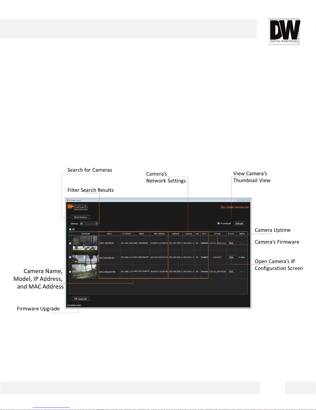
DW IP FINDER™ *
Using DW IP Finder™ Software
Use DW IP Finder™ to change the basic settings of your MEGApix®
CaaS™ camera, update firmware for multiple cameras simultaneously or
connect to your MEGApix® CaaS™ camera.
14
Page 15
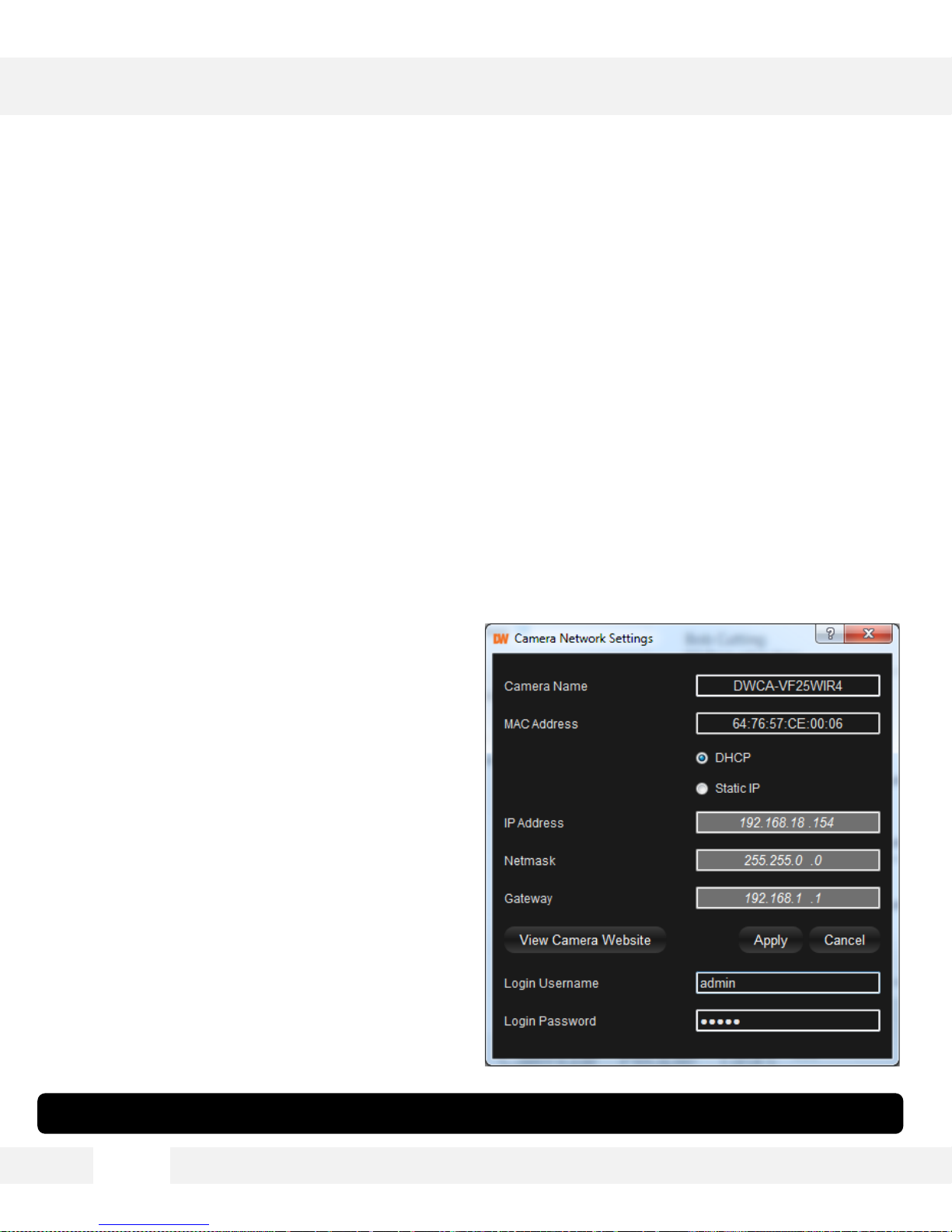
DW IP FINDER™ *
Using DW IP Finder™ Software
Use DW IP Finder™ to set the connection type and the IP address
information for your MEGApix® CaaS™ camera.
1. DHCP: Select DHCP to access the camera within the same internal network. For further
explanation on DHCP, please see page 17.
2. Static IP: Select Static to connect to the camera from an external network . For further
explanation on Static, please see page 17.
3. If STATIC IP is selected, manually enter the camera’s IP address, netmask and gateway .
These need to match the sett ings of your network. Please contact your network administrator
for more information.
4. To apply changes, enter the camera’s
username and passwor d and cli ck ‘Apply ’.
5. To view the camera’s web client for additional
setup options, pr ess the ‘ View Camera
Website’ button.
*If you change the camera’s IP, write down the camera’s MAC Address for identification in the future.
15
Page 16

DW IP FINDER™ *
DHCP
The Dynamic Host Config ur a ti o n Protocol (DHCP) is a network configura t ion protocol that al l ows a
device to configure automatically according to the network it is connected to.
If your network supports D H CP and your MEGApix® CaaS™ camera is set to DHCP, IP Finder will
automatically find and set your MEGApix ® CaaS™ camera to correspond with your network
requirements.
Static
Static IP addresses are recommended when using a network that does not suppor t D H C P or when
setting your device to be accessed ex ternal ly via the internet. If Static is selected, you must
manually enter t he cor r ect network settings for your MEGApix® CaaS™ camera. The setting s wi ll
correspond with your network. To set your camera to a static IP address, we recommend that you
(1) setup the camera to DHCP, (2) allow it to configure itself according to your network, and (3)
change the setting s to a static IP address.
1. To set your MEGApix® CaaS™ camera to Static, hig hlig ht the desired dev ice from the search
results list, and click on Configuration. In the “Network Configuration” window, make sure
Static is selected.
2. Enter the following informati on: IP Address, Netmask, Gateway, and Preferred DNS.
3. Click Apply and Reboot to save all changes.
16
Page 17

DW IP FINDER™ *
Upgrading Cameras using the DW IP Finder™
Use the DW IP Finder™ to perform firmware upgrade to all your
MEGApix® CaaS™ cameras from one convenient location.
1. Press the ‘Firmwar e’ button.
2. In the Firmware Upload secti o n, browse and sel ect the appr opr i a te firmware file to use.
3. Select all the cameras you would like to upgrade. You can select multiple cameras by clicki ng
on multiple camera models while holding dow n the Ctrl button*.
4. Click ‘Update Cameras’.
5. The system will indic ate if the upgrade was successful or not for each camer a.
6. When all cameras have been upgraded, restart the cameras to apply the new firmware.
7. Allow up to 60 seconds for the cameras to reboot and press the ‘Search’ button. If the
cameras reappear in the IP Finder the reboot is complete and the camera is ready.
14
Page 18

CAMERA REBOOT*
Resetting the Camera
Pressing the reset button on the camera’s back for five (5) seconds will
initialize all environmental variables to factory default. Previous setup
for IP default, time, etc. will be deleted. If a system’s IP address is
lost, reset the camera back to factory default.
The following are the default netw or k setting s.
IP Mode DHCP
IP Address 169.254.X.Y
Subnet Mask 255.255.255.0
Gateway ---
HTTP Port 80
* Frequent use may cause system error.
17
Page 19

WEBVIEWER*
Remote Video Monitoring Via Internet Explorer
Monitor and configure the MEGApix® CaaS™ camera through a built- in
web viewer.
1. Ty pe the I P address of t he camer a in an Internet Explorer window.
Example: http://192.168.1. 123 (Factory Default)
2. Enter Username and Password
Default: Username: admin | Password: admin
3. The web browser may ask to install FbVLC to view video from the camera. Once it has been
installed, Internet Ex plorer wil l display vi deo images from the camera.
4. The Web Client is also available in Googl e Chr ome, Safari and F irefox web view ers . Please
note that features may be limited.
18
Page 20

WEBVIEWER*
GUI Description
Monitor and configure the MEGApix® CaaS™ camera through a built- in
web viewer.
1. Live video display- This is the region for live video str eam from the camera.
2. Setup Menu- Setup the camera’s V ideo, N etwor k, Events, System etc.
3. Stream selection- Select a stream to display it in the viewing area.
4. Full Screen- Expand the camera’s view into full screen.
5. Menu options suc h as PTZ, audio, sens or and backup options will be disabled for cameras
that do not support those functions.
19
Page 21

WEBVIEWER*
First Stream & Second Stream
Configure up to two (2) stream settings for monitoring and recording.
On the main monitoring page, user can v i ew the camera w i th the Fir s t Stream sett ings or
secondary Stream setti ngs . The camera s upports the s etup of up to two (2) different streams w it h
different r esol uti on , and FPS for maximum network control. Sel ect which stream to view in the
camera’s main menu by selecting one of the options from the drop-down menu. Streams that are
not enabled in t he Str eams Set up page will not appear in the drop-down menu.
For Setup Stream Settings, refer to page 25-26.
[Streams
Selection]
20
Page 22

WEBVIEWER*
Export Image (On Supported Models)
Export a screenshot of the current live video to your computer.
1. Export a screenshot of the camera’s view with date/time and camera’s name overlay by
pressing the CAPTURE button.
2. You can also print the camera’s view for your records by pressing the P RI NT button. The
printing setup page w il l appear, allowing you to adjust the printer’s options, add notes and the
camera’s informatio n as text overlay.
*NOTE: Some of these features may be disabled for cameras that do not support these functions.
[Backup &
Export]
21
Page 23

WEBVIEWER*
Audio Control (On Supported Models)
Enable two- way audio for supported cameras.
Speaker
1. For cameras supporting audi o, c heck the box next to SPEAKER to hear audio from the camera.
2. Make sure your camera supports audio from external devices or includes a microphone built-in.
3. If needed, adjust the camera’s vol ume using the volume bar.
Microphone
1. For supported cameras, enable audio to be transmitted from the w eb view er to the camera by
checking the box next to MIC.
2. Make sure your camera supported external devices for audio.
Please note that audio from the camera and microphone from the viewer cannot operate at the same
time. To enable one, make sure the other is disabled.
[Audio
Control]
23
Page 24

WEBVIEWER*
Alarm Input and Relay Output (On Supported Models)
Control external devices connected to the camera such as alarms and
sensors.
Alarm Input
1. When any of the camera’ s Alarms are activated, the c or res pon d i ng number will turn on and
be displayed in color . This function w ill be available for supported cameras that support alar m
input.
Relay Out
1. For cameras that support relay output control, enable or disable the relay directly from the
camera’s web view er. Relay output will be disabl e d when the check box next to it is
unchecked. When t he chec k box is checked, the r el ay output will be activated. This function
will be available for supported cameras that support relay output.
[Alarm &
Relay Control]
24
Page 25

WEBVIEWER*
Setup > Basic > Video
The MEGApix® CaaS™ camera allows you to setup 2 different streams to
optimize storage and bandwidth usage.
1. Ty pe (Codec )- Select the type of compression to use when outputting the v ideo. The compressi on
type affects the image quali ty, bandwidth, and file siz e of saved images. MJPEG, the lowes t
Compression type, w i ll provide the highes t imag e quali ty, but also wil l cause the image siz e to be
the largest, and take up the most bandwidth. H.264 Mainline Profile is the default codec. If OFF is
selected, this st ream will not be enabled.
2. Resolution- Set Resolution for each stream. The better the resolution, the more bandwidth it will
require to stream images.
3. Encode FPS- Select from 0fps to 30fps. The camera is set by default to 30fps.
4. Flip & Rotate- Select whether to flip the stream’s image verticall y or rotate it.
25
Page 26

WEBVIEWER*
Setup > Basic > Video
The MEGApix® CaaS™ camera allows you to setup 2 different streams to
optimize storage and bandwidth usage.
1. Advanced Stream Settings: H.264-
a. GOP Size – This sets the number of I-frames and P-frames per second. If GOP is set to 30, the camera will record 1
I-frame and 29 P-frames. To improve the recording quality, lower the GOP number. However, the lower the number,
the larger streaming file size will be.
b. Bitrate Control – Select the appropriate bitrate control option from the drop-down menu options.
c. Minimum and Maximum Bitrate – Set the min and max values for the camera’s bitrate range.
d. Min/ Max Bitrate – If VBR Bitrate mode is selected, adjust the minimum and maximum bitrate levels.
Frist Stream: Max 8Mbits, Min 1 Mbit
Second Stream: Max 6Mbits, Min 0.5 Mbits
e. Average Bitrate – If CBR Bitrate mode is selected, adjust the average bitrate.
2. Advanced Stream Settings: MJPEG QualitySet MJPEG image quality from 25 to 85. The
higher the quali ty, the more bandwidth will be
required to stream the image.
3. Advanced Stream Settings: Over lay - Select
to show/ hide time stamp and select the text
color . The time stamp w il l appear on the top
left side of the camera’s view.
4. Select ‘Apply’ to save changes.
26
Page 27

WEBVIEWER*
Setup > Basic > Motion Detection
The MEGApix® CaaS™ camera allows you to setup four (4) motion
detection masks in the camera’s Field of View.
The camera supports up to four (4) separate motion detecti on reg ions. To setup motion detection:
1. Select the region you wish to setup from the ‘Choose Region ’ drop-down menu.
2. To set the region’s pos i ti on and size in the camera’s vi ew, go to the camera’s vi ew above the
settings and click and hold wi th your mouse and drag acros s the camera’ s vi ew. The region’s size
and position will be display ed ov er the camera’s vi ew in a blue layer. If you have more than one
region setup, the region in curr ent setup w ill be highlighted w it h a yellow border.
3. Ty pe: Select w hether thi s regi on wil l include moti on detec tion or exclude it. If exclude is selected,
motion in this region WILL NOT be detected.
4. Size: Select the siz e of the objec t you want to detect moti on . The larger the percentage, the l arger
the object causing moti on will have to be in
order for the camera to detect the motion.
5. Sensitivity: Set the camera’s sensitivity to
motion in the regi on. The higher the
percentage, the more sensit iv e the camera
will be to motion in that r eg i on.
6. Click ‘Apply Chang es’ to save.
7. When motion occurs in a region set to detect
motion, the camera will display a motion
indicator in the c amera’s web viewer.
NOTE: motion indicator is not supported in
Internet Explorer vi ew er.
27
Page 28

WEBVIEWER*
Setup > Basic > Edge
The MEGApix® CaaS™ camera support edge storage with DW Spectrum
CaaS™.
1. SD Card: this setup screen allows you to vi ew your SD card’ s i nforma ti o n , format the SD card and
install DW Spectrum Edge™ for local edge r ecording .
NOTE: For DWCS-VF35W4-64, DWCS-VF35WIR4-64, and DWCS-VF35W28-64, a 64GB SD
card is included with the camera and should prepopulate in this section.
2. The system will automatically display all installed SD cards. If your SD card does not appear in the
table, try rebooting the camera and re-inserting the card.
3. The system will displ ay t he SD C ar d’s total size, current used and free spac e, format type and
current recording status.
4. To format the SD Card, press the ‘For mat SD C ar d’ button. This will erase any data on the SD
Card and format it.
5. To add the edge capability to the camera,
please install the DW Spectrum CaaS™
software. This softwar e w ill allow you to
record locally to the camera, use the failov er
redundancy feature and contr ol y our camera
as any other server using the DW Spectrum™
IP VMS software.
6. To download the DW Spectrum CaaS™
software and for more information, please go
to Digital Watch dog’s website at
www.digital-watchdog.com.
28
Page 29

WEBVIEWER*
Setup > Basic > Edge > DW Spectrum CaaS™
The MEGApix® CaaS™ camera support edge storage with DW Spectrum
CaaS™.
To install the DW Spectrum CaaS™ softwar e:
1. Press the INSTALL button.
2. In the new popup w indow, press the ‘Choose File’ button and select the appropriate file.
3. Press the UPLOAD button.
4. The system will upload the file. SUCCESS wil l appear once the ins tallati on is complete.
5. Once the DW Spectrum CaaS™ software is
installed on the camera, you can
stop or restart the now installed DW
Spectrum CaaS™ serv er, update the
software or remove it from the camera.
29
Page 30

WEBVIEWER*
Setup > Basic > Edge > DW Spectrum CaaS™
The MEGApix® CaaS™ camera support edge storage with DW Spectrum
CaaS™.
Once the DW Spectrum CaaS™ software is installed on the c amera, the camera is considered a DW
Spectrum server. As such, all settings for the camera’s recor ding , play back, bac kup, and further
software updates can be done from the DW Spectrum cli ent.
1. To access the camera via DW Spectrum client, please install the client softw are incl uded i n the
accessory CD.
2. Run the DW Spectrum software.
3. Enter the camera’ s I P address i n the l og i n s cr een.
4. See the DW Spectrum manual for more information on DW Spectrum operation.
SPECTRUM_EDGE-IPCAM
1920x1080 10.00fps @ 1.96Mbps (H264) Hi-Res LIVE
30
Page 31

WEBVIEWER*
Setup > Camera > Day & Night Control
Adjust the MEGApix® CaaS™ camera’s Day & Night, Image and Color
settings.
1. Day / Night – select the camera’s color mode.
a. Auto – The camera will switch between color and B/W automatically based on the levels of light in the camera’s Field
of View (FoV).
b. Force Day – Manually use the camera’s True Day/Night IR cut filter the camera’s view to day mode regardless of the
light levels in the camera’s FoV.
c. Force Night – Manually removes the True Day/Night IR cut filter from the camera’s lens and turns the camera’s view
to night mode regardless of the light levels in the camera’s FoV.
2. Advanced Settings – The camera will switch by default to B/W in night mode. You can manually
select what action the camera wi ll take in night mode under the adv anced settings . You can
change the setting s by selec ti ng C ol or in t he advanced settings.
31
Page 32

WEBVIEWER*
Setup > Camera > Image Setting
Adjust the MEGApix® CaaS™ camera’s Day & Night, Image and Color
settings.
1. BASIC SETTINGS
a. 3D Digital Noise Reduction – Control the level of noise in the image. Select from Off, Low, Medium and High. The
higher the level, the more the camera will manipulate the image to reduce digital noise, but it will also increase lagging
when motion occurs. By default, the 3D DNR settings are set to Low.
b. Digital WDR (Wide Dynamic Range) – The Digital Wide Dynamic Range is used when there are extremely bright and
extremely dark areas in the VoF of the camera. Select to enable or disable this feature. By default, Digital WDR is set
to ON.
c. BLC (Backlight Compensation) – This setup option allows you to adjust the camera’s capture of light when there is
strong backlight in the camera’s Field of View [FoV]. By default, BLC is set to OFF.
d. Exposure Control – In case the camera’s image is flickering, adjust the value on this setting. By Default, Exposure
Control is set to 60GHz.
2. EXPOSURE SETTING
a. Slowest Level – Set the shutter speed from the
available options between 1/7.5 and 1/8000.
Select 1/7.5 to set more exposure time to light. This
setting is used to make movements look natural/
unfrozen. Select 1/8000 to set less exposure time to
light. This settings is used to catch fast moving objects.
b. Sensor Max Gain – Maximum light gain settings in low
light conditions. Select from 26dB (least light), 30dB,
36dB to 42dB (most light). Default value is 36dB
c. Fastest Exposure – Set the shutter speed from the
available options between 1/25 and 1/32000.
Select 1/25 to set more exposure time to light. This
setting is used to make movements look natural/
unfrozen. Select 1/32000 to set less exposure time to
light. This settings is used to catch fast moving objects.
d. Metering Mode – This is the region of interest for the
exposure settings. The camera’s exposure will be
determined by the selected Metering Mode, affecting
the camera’s bright levels. Select an option from the
available drop-down options.
e. Custom Metering Area – If ‘Custom’ is selected in the
Metering Mode, adjust the Metering Mode position in
the camera’s FoV. Select an option from the available
drop-down options.
32
Page 33

WEBVIEWER*
Setup > Camera > Color Setting
Adjust the MEGApix® CaaS™ camera’s Day & Night, Image and Color
settings.
1. Saturation – Set the camera’s saturation levels from 0 ~ 255. The higher the number, the more
vibrant will the colors appear on the camera’s image. The lower the number , the more black and
white the image will appear. Default value is 64.
2. Brightness – Set the brightness of the camera’s image from -255~255. The higher the number, the
brighter the camera’ s imag e wi ll appear. Default value is 0.
3. Hue – from -15 ~ 15. The higher the number, the camera’s image w i ll use warmer tones. The
lower the number, the camera’s image will use cooler color tones. Default v alue is 0.
4. Contrast – Set the camera’s contrast betw een 0 ~ 128. The higher the number, the contrast
between the dark and bright areas in the camera’s FoV will be more distinct. Default value is 64.
5. Sharpness – Sets the image sharpness betw een 0 ~ 255. The higher the number, the sharper the
image. Default value 128.
6. White Balance Control – This gives the
camera a reference to “true white.” White
Balance is used to make colors appear the
same in the Field of View (FoV) no matter
what is the light temperature of the light
source. Select form the available drop-down
menu options.
7. White Balance Method – Select the Custom,
Normal, or Gray World.
33
Page 34

WEBVIEWER*
Setup > System > About System
View the MEGApix® CaaS™ camera’s basic information.
This page displays the camera’ s main informa tion i ncludin g :
1. Camera’s Date And Time – Displays the camera’s curr ent date, ti me and time zone.
2. Camera’s Uptime– how long the camera has been operating sinc e its last power cyc le
3. Code V ersi on – camera’s firmware ver sion.
4. MAC & IP Address – the camera’s address information.
5. Camera Name – display the camera’ s name.
6. Camera Model – displays the camera’s model number
7. SD Card Information - displays the size of all SD cards currently mounted on the camera.
8. Port – displays the web port for the camera.
9. SD Card Status – displays the current SD
card’s status, s i z e and r emai ning space.
34
Page 35

WEBVIEWER*
Setup > System > Network Setting
View the MEGApix® CaaS™ camera’s basic information.
This page displays the camera’ s main informa tion i ncludin g :
1. IP Type – Select whether the camera’ s IP address w ill be static or DHCP. Select DHCP if you are
using a DHCP Server. When the camera is set to DHCP, it will obtain all its netw ork i nformatio n
automatically from the ser ver. If you do not have a DHCP server, or wish to manually enter t he
camera’s netw ork information , selec t STA TIC. T o obtai n a static IP Address and network
information, contact your Internet Service Provider (ISP) or Network Administrator.
2. IP Address– Enter an IP address for the camera
3. Netmask – default is 255.255.255.0
4. Gateway – This is your router’s external IP address. This address is used when accessi ng t he
camera remotely from outside the network. The router will channel the data request to the
appropriate port associated wit h the camera.
5. DNS – Enter a DNS address. The Domain
Name Server translates a web addresses to
an IP addresses.
6. Camera Name – If needed, rename the
camera for proper identification.
7. UPnP – Enable or disable the camera’s
UPnP function according to your network
requirements.
8. Web Port – By default, t he camer a’s web port
is set to 80. These are the port s nec ess a r y in
order to communicate with the camera when
accessing from a different netw ork. Some
ISP may block port 80. Pl ease contact your
Network Administr ator for additional
information.
35
Page 36

WEBVIEWER*
Setup > System > Date & Time
View the MEGApix® CaaS™ camera’s basic information.
This page displays the c amera’s current time and date & time setting opt ions :
1. Camera Time–This section displays the camera’ s current date, time, and time zone.
2. Time Zone– Select the appropriate time zone from the drop-dow n menu.
3. NTP Server– Set the camera to sync its time with an NTP server by pressing the ‘SYNC’ button.
4. Computer T ime– You can also set the camera to sync its time wit h your computer’s settings by
pressing the ‘SYNC’ button.
Setup > System > User Setting
Use the User Setting pag e t o set a new password for the camera’s admin user. To change the
admin’s pas sword, type and retype the new password in the corresponding fields and click ‘Apply’.
36
Page 37

WEBVIEWER*
Setup > System > Firmware Upgrade
View the MEGApix® CaaS™ camera’s basic information.
Use this setting page to upgrade the camera’ s firmw are. The informatio n at the top of the page shows
the camera’s name, current firmware version and date. To check for the latest firmwar e, click on the
link to Digital Wa t ch dog’s website, or go to www.digital-watchdog.com.
To start the upgrade proc ess:
1. Download the latest firmw are from the Dig ital Watchd og w ebsit e.
2. Click the ‘Browse’ button and select the firmware file.
3. Press the ‘Upload’ button.
4. The system will automatically start the upgrade proc ess.
5. You can track the upgrade process i n the update status page.
6. Once the upgrade is complete, the camera will reboot to complete the update.
37
Page 38

WEBVIEWER*
Setup > System > Factory Reset
View the MEGApix® CaaS™ camera’s basic information.
The Factory Rest page all ows you to reboot the camera or reset its settings to factory defaul t.
1. Reboot – press the ‘Reboot’ button to reboot and power cycle the camera.
2. Factory Reset wi thout IP – Select to reset the camera’s settings back to factory default. If this
option is selected, all settings except for the camera’s network settings with be deleted and r es et
to their factory default. Pr ess OK in the confir ma ti o n window to complete the reset.
3. Factory Reset wi th IP – Select to reset the camera’s settings back to factory default. If this opti on
is selected, all settings, including the camera’s netw ork settings, with be deleted and reset to their
factory default. Pr ess OK in the c onfirmati o n window to complete the reset.
38
Page 39

SPECIFICATIONS*
IMAGE
Image Sensor 1/3" 2.1MP CMOS Sensor
Total Pixels 2304 (H) x 1536 (V) 1.55μm
DWCA-VF25W28, DWCA-VF25W28-64: F1.8 (30IRE): 0.06Lux [Color], F2.0
(30IRE): 0.02Lux [B&W]
Minimum Scene Illumination
Focal Length
Lens Type Fixed Lens
IR Distance 30ft Range IR (IR models only)
DWCA-VF25WIR4, DWCA-VF25WIR4-64, DWCA-VF25W464: F1.4 (30IRE): 0.5
Lux [Color], F1.4 (30IRE): 0.001 Lux [B&W]
DWCA-VF25WIR8, F2.0 (30IRE): 0.5Lux [Color], F2.0 (30IRE): 0.00Lux [B&W]
DWCA-VF25W28, DWCA-VF25W28-64: 2.8mm, F1.4, 102° Viewing Angle
DWCA-VF25WIR4, DWCA-VF25WIR4-64, DWCA-VF25W464: 4.0mm, F1.8, 86°
Viewing Angle
DWCA-VF25WIR8: 8.0mm, F2.0, 39° Viewing Angle
OPERATIONAL
Brightness -255 ~ 255
Shutter Mode Auto/ Manual
Shutter Speed
Digital Slow Shutter (DSS) Off, 2x, 4x
Smart DNR™ Digital Noise Reduction Off/ Low/ Middle/ High
Auto Gain Control Max 41dB
1/7.5, 1/15, 1/25, 1/30, 1/50, 1/60, 1/100, 1/120, 1/240, 1/480, 1/960, 1/1024,
1/8000, 1/16000, 1/32000 sec
BLC (Back Light Compensation) Off/ On
Digital Wide Dynamic Range (DWDR) Auto/ Off
Day and Night Auto/ Day (Color)/ Night (B/W)
Motion Detection: Sensitivity Low/ Middle/ High
Memory Slot SD/SDHC Micro Memory Card (Card is not included), up to 128GB
Hue -15 ~ 15
Saturation 0 ~ 255
Sharpness 0 ~ 10
Flip & Rotate Yes
39
Page 40

SPECIFICATIONS*
NETWORK
LAN 802.3 Compliance 10/100 LAN
Video Compression Type H.264, MJPEG
Resolution 1920 x 1080 ~ 160 x 90
Frame Rate 30fps at 1080P Resolution
Stream Capability Multi Streaming CBR/VBR (Controllable Frame Rate and Bandwidth)
IP IPv4, IPv6
Protocol ONVIF, TCP/UDP, RTSP/HTTP/HTTPS/FTP
Maximum User Access 4 Users
Memory Slot Micro Memory Card, up to 128GB
ONVIF Conformance Yes
Web Viewer
Video Management Software DW Spectrum™, ONSSI, Milestone, Genetec
Supported OS: Windows XP, Windows Vista, Windows 7, MAC OS
Supported Browser: Internet Explorer, Google Chrome, Mozilla Firefox, Safari
ENVIRONMENTAL
Operating Temperature -10°C ~ 45°C (14°F ~ 113°F)
Operating Humidity Less than 90% (Non-Condensing)
IP Rating IP66 Certified (Weather Resistant)
Other Specifications CE, FCC, RoHS
Electrical
Power Requirement DV12V, PoE [IEEE802.3af, Class 2]
Power Consumption
IR LED Off: 2.2W, 180mA
IR LED On: 3W, 255mA
Mechanical
Housing Material Aluminum Die-Casting
Dimensions Ø 125 x 74.3 mm (Ø 4.9 x 2.9 inch)
Weight 1.5 lbs
40
Page 41

TROUBLESHOOTING
Before sending your camera for repair, check the following or contact your technical specialist.
I can’t find my MEGApix® CaaS™ camera on the IP Finder software.
Is the PoE cable connected properly?
Make sure cable is tightly connected at both ends. It should make a “click” sound when connected properly.
Make sure cable is intact and there are no cuts or exposed wires.
If Yes, are the camera’s LED light turned on and blinking?
The camera’s LED lights indicate that the camera is powered on. Blinking LED light indicate that the camera has
finished booting up and is transmitting data.
If Yes, is the internet working properly?
Make sure you can connect to the internet with other devices on the network (ex. Your Computer). Your internet
could be temporarily down.
If Yes, if using a power adaptor, does it meet camera’s power requirements?
Power Requirements: DC12V (IR LED Off: 2.2W, 180mA, IR LED On: 3W, 255mA), PoE Ports (Class 2, less
than 5W)
If Yes, if using PoE Switch, is it connected to a proper internet outlet and operating properly?
Make sure the PoE Switch is connected to a router/modem and the ports that have devices connected to them
have a green LED on.
If Yes, is the computer on the same network as the MEGApix® CaaS™ camera?
Camera and computer should be connected to the same router. Contact your network administrator if you have
more than one network available.
If Yes, try pinging the IP camera’s default IP address 169.254.X.X
From your desktop, go to Start > Programs > Accessories > Command Prompt. Type “ping 169.254.X.X” and
press Enter. If you get the message “Request timed out,” camera is not connected. Camera is connected if you
get data.
If Yes, try connecting the camera to a different port in the PoE Switch.
That specific Switch Port may be damaged or currently not working properly.
If Yes, try resetting the camera to default settings.
Press the 2 buttons in the back together and hold for 5 seconds. The camera will return to factory default with
default IP address 192.168.1.123. If your network supports DHCP, the camera will be found using the IP Finder
software with an IP address that matches your network’s requirements.
41
Page 42

TROUBLESHOOTING
Before sending your camera for repair, check the following or contact your technical specialist.
I can’t connect to my MEGApix® CaaS™ camera through the Web Browser
Are the camera’s LEDs on and blinking?
The camera’s LED indicates the camera is On. If the LED blinks, the camera has finished booting up and is
transmitting data.
If Yes, is the internet working properly?
Make sure you connect to the internet with other devices on the network (ex. Your Computer). Your internet
could be temporarily down.
If Yes, is the computer on the same network as the IP camera?
Camera and computer should be connected on the same router. Contact your network administrator if you have
more than one network available.
If Yes, try pinging the MEGApix® CaaS™ camera’s IP address as it appears on the IP finder.
From your desktop, go to Start > Programs > Accessories > Command Prompt. Type “ping” followed by the
camera’s IP address; then, press Enter. If you get the message “Request timed out,” camera is not connected. If
you get data back, that means the camera is connected.
If Yes, try connecting the camera, to a different port in the PoE Switch.
That specific Switch Port may be damaged or currently not operating properly.
If Yes, check your security settings on your internet browser.
Try adding the camera’s IP address to the trusted sites list in your Internet Options. *Setup may vary depending
on the browser you use.
42
Page 43

TROUBLESHOOTING
Before sending your camera for repair, check the following or contact your technical specialist.
I can’t see the live video of my MEGApix® CaaS™ camera.
Are you trying to view the camera’s video from an Internet Explorer browser?
Make sure you have the minimum PC requirements to view the MPA20M camera. *See below for more
information.
If Yes, did you install all required FbVLC files? These are VLC media files that allows the camera to stream its
video to the web client.
When you connect to your MEGApix® CaaS™ camera for the first time, your browser will ask you to install
FbVLC. Make sure your Web Browser’s security settings do not block pop-up windows and allows FbVLC files
to be installed and used. *Setup may vary depending on the browser you use.
If Yes, make sure nothing is blocking the camera’s lens.
W eb Viewer Specifications
Minimum Requirements for PC
CPU Intel P4 2.0GHz Dual Core
RAM More than 1GB
HDD 200 GB Required for Saving Clip Image
OS Microsoft Windows XP or Higher
Resolution Higher than 1024X768
43
Page 44

TROUBLESHOOTING
Before sending your camera for repair, check the following or contact your technical specialist.
Setting the IP Address for your PC
Dynamic Host Configuration Protocol (DHCP) is the default setting for the camera.
If the MEGApix® CaaS™ camera is connected to a DHCP network and the camera’s IP Configuration Mode is set to
DHCP, the server will automatically assign an IP address to the camera. If the camera is using DHCP, the default IP
address will be 192.168.1.123, and the default subnet mask will be 255.255.255.0.
The MEGApix® CaaS™ camera can also connect to the web viewer using a static IP address. This will allow you to
set your own IP address manually.
Setup the Network Protocol on your PC.
1. Go to Network icon on your PC.
2. Right-click and select Properties.
3. Double-click Local Area Connection.
4. Click Properties.
5. Double-click Internet Protocol Version 4 (TCP/IPv4).
6. Select Obtain an IP address automatically to set the computer to a dynamic IP address, or select Use the
following IP address to set the computer to a static IP address.
7. If the option Use the following IP address has been selected, setup the IP address as 192.168.1.XXX. The last
three digits should be a number between 1 and 254.
44
Page 45

WARRANTY INFORMATION*
Digital Watchdog (referred to as “the Warrantor”) warrants the Camera against defects in materials or workmanships
as follows:
Labor: For the initial two (2) years from the date of original purchase if the camera is determined to be defective, the
Warrantor will repair or replace the unit with new or refurbished product at its option, at no charge.
Parts: In addition, the Warrantor will supply replacement parts for the initial two (2) years.
To obtain warranty or out of warranty service, please contact a technical support representative at 1-866-446-3595
Monday through Friday from 9:00AM to 8:00PM EST.
A purchase receipt or other proof of the date of the original purchase is required before warranty service is rendered.
This warranty only covers failures due to defects in materials and workmanship which arise during normal use. This
warranty does not cover damages which occurs in shipment or failures which are caused by products not supplied by
the Warrantor or failures which result from accident, misuse, abuse, neglect, mishandling, misapplication, alteration,
modification, faulty installation, set-up adjustments, improper antenna, inadequate signal pickup, maladjustments of
consumer controls, improper operation, power line surge, improper voltage supply, lightning damage, rental use of the
product or service by anyone other than an authorized repair facility or damage that is attributable to acts of God.
45
Page 46

LIMITS & EXCLUSIONS*
There are no express warranties except as listed above. The Warrantor will not be liable for incidental or consequential
damages (including, without limitation, damage to recording media) resulting from the use of these products, or arising
out of any breach of the warranty . All express and implied warranties, including the warranties of merchantability and
fitness for particular purpose, are limited to the applicable warranty period set forth above.
Some states do not allow the exclusion or limitation of incidental or consequential damages or limitations on how long
an implied warranty lasts, so the above exclusions or limitations may not apply to you. This warranty gives you specific
legal rights, and you may also have other rights from vary from state to state.
If the problem is not handled to your satisfaction, then write to the following address:
Digital Watchdog, Inc.
ATTN: RMA Department
5436 W Crenshaw St
Tampa, FL 33634
Service calls which do not involve defective materials or workmanship as determined by the Warrantor, in its sole
discretion, are not covered. Cost of such service calls are the responsibility of the purchaser.
46
Page 47

Headquarters Office: 5436 W Crenshaw St, Tampa, FL 33634
Sales Office: 16220 Bloomfield Ave., Cerritos, California, USA 90703
PH: 866-446-3595 | FAX: 813-888-9262
www.Digital-Watchdog.com
technicalsupport@dwcc.tv
Technical Support PH:
USA & Canada 1+ (866) 446-3595
International 1+ (813) 888-9555
French Canadian 1+ (514) 360-1309
Technical Support Hours: Monday-Friday
9:00am to 8:00pm Eastern Standard Time
 Loading...