

Page 1
Page 2

1 | H.264 Digital Video Recorder
C
return and for long-term storage of the DVR unit.
Safety Information
The safety information is provided for the wellness of the equipment and for the safety of the
operator.
Please review and observe all instructions a nd w arnings in this manual.
Note: Keep this manual handy every time you operate this equipment. Also, check with your dealer
for further assistance and for the latest revision of this manual. Your dealer might provide you with a
digital version of this manual. We also ask to keep the original box and packing materials in case of
Preparations before installation
T o protect your DVR from damage and to optimize performance, be sure to keep the DVR away from dust, humidity, and areas
with high voltage equipment such as a refrigerator.
Do not install or place equipment in areas where the air vents can be obstructed, such as in tight enclosures or small utility
closet. Keeping the unit in a temperature-controlled room with ample regulated power is highly recommended. Do not
overload the wall outlet, as this can res ult in the r isk o f fire or ele ctr ic sho ck.
Uninterruptible power devices such as UPS power surge protectors are recommended, and the DVR units must at least be
connected with UL, CUL, or CSA approved power surge protector. Avoid direct sun light and avoid heat.
FCC Information
This equipment has been tested and found to comply with the limits of Class A digital device,
pursuant to part 15 of the FCC Rules. These limits are designed to provide reasonable protection
against harmful interference when the equipment is operated in a commercial environment. This
equipment generates, uses, and radiates radio frequency energy, and if not installed and used in
accordance with the user manual, it may cause harmful interference to radio communications.
user will be required to correct the interference at his own expense. Changes or modifications not expressly approved by the
party responsible for compliance could void the user's authority to operate the equipment under FCC rules.
Operation of this equipment in a residential area is likely to cause harmful interference, in which the
UL Information
- For pluggable equipment, the socket-outlet shall be installed near the equipment and shall be easily accessible.
- If the battery is placed elsewhere in the equipment, there shall be a marking close to the battery or statement in the servicing
instructions.
AUTION
RISK OF EXPLOSION IF AN INCORRECT BATTERY TYPE IS USED.
DISPOSE OF USED BATTERIES ACCORDING TO THE INSTRUCTION.
THIS EQUIPMENT IS FOR INDOOR USE, AND ALL THE COMMUNICA T ION WIRING IS LIMITED TO INDOORS.
Page 3

User Manual | 2
Contents
CHAPTER 1 : DVR USER MANUAL
1 GETTING STARTED 6
1.1 Checking Supplied Items 6
1.2 System Application Overview 7
1.3 System Startup and Shutdown 8
1.4 Front Panel 9
1.5 Rear Panel 12
1.6 IR Remote Controll er 15
2 OPERATION 16
2.1 User Login 16
2.2 Live Display Mode 17
2.3 Freeze Mode 22
2.4 Call Monitor Operation 23
2.5 PTZ Operation 24
2.6 Instant Playback of Recorded Video 26
2.7 Clean Button During Playback 27
2.8 I-Backup (Quick Backup During Playback) 28
2.9 Search Recording Image 29
2.10 DST Setting and Screen Saver 34
3 SETTING 37
3.1 System 39
3.2 Device 46
3.3 Record 51
3.4 Network 58
3.5 Backup 63
3.6 Quick Setup 65
4 WEB SURVEILLANCE 66
4.1 Web Login 66
4.2 Web Configuration 66
4.3 Web Moni t ori n g 69
4.4 Web Playback 71
Page 4

3 | H.264 Digital Video Recorder
CHAPTER 2 : ACS CLIENT SOFTWARE USER MANUAL
5 ACS (ADVANCE CLIENT SOFTWARE) USER GUIDE 74
5.1 Recommended PC Requirements 74
5.2 Install 75
5.3 Uninstall 77
5.4 Basic Operation 78
5.5 Advanced Operation 84
5.6 ACS Setup 88
CHAPTER 3 : MAC ACS CLIENT SOFTWARE USER MANUAL
6 MAC ACS USER GUIDE 94
6.1 Mac Requirements 94
6.2 Install 95
6.3 Basic Operation 97
CHAPTER 4 : MOBILE PHONE SOFTWARE USER MANUAL
7 MOBILE PHONE SOFTWARE USER GUIDE 106
7.1 iPhone Application Software 106
7.2 Android Application Software 110
7.3 Blackberry Application Software 115
7.4 Using WAP+3G Connection 120
APPENDIX : SPECIFICATION 123
Page 5
User Manual | 4
Chapter 1
DVR USER MANUAL
Page 6

5 | Chapter 1 : DVR User Manual
Page 7
User Manual | 6
1 GETTING STARTED
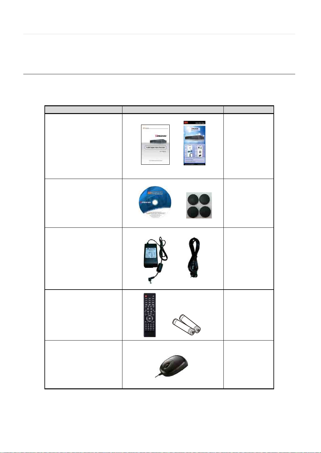
1.1 Checking Supplied Items
Make sure that you have the following items supplied with your DVR. If any of these items are missing or damaged, notify your
vendor immediately. Do not dispose of the packing utilities in case of moving or storage purposes.
Items Photo Quantity
User Manual
(DVR & Software)
Quick Start Guide
CD (Manual & Software)
and Rubber Mount
12V DC Adaptor
and Power Cable
IR Remote Controller
And Batteries
1
1
1
1 Set (4 Pieces)
1
1
1
2
USB Mouse
1
Page 8
7 | Chapter 1 : DVR User Manual
N
W
!
1.2 System Application Overview
This section describes how to connect peripheral devices to the DVR according to your application.
Install the DVR on a flat surface. If required, attach a rubber mount for installation. If a 19-inch rack is used with 1.5U Height
case, it is recommend to install the system on a shelf and use 2.5~3U (1U=1 . 75 in ch space for proper ventilation.
OTE
Place the DVR into the rack require tow people to hold the DVR in place.
Install the DVR in a location with good ventilation to prevent overheating.
ARNING
※ When connecting the power supply to the DVR , it is strongly recommended to use a UPS (Uninterruptible Power Supply)
Page 9
User Manual | 8
N
N
1.3 System Startup and Shutdown
1.3.1 System Startup
After connecting peripheral devices such as cameras, monitors, and a mouse to the DVR, connect the 12vDC 6.6Amps power
supply to the power jack on the rear panel of the DVR.
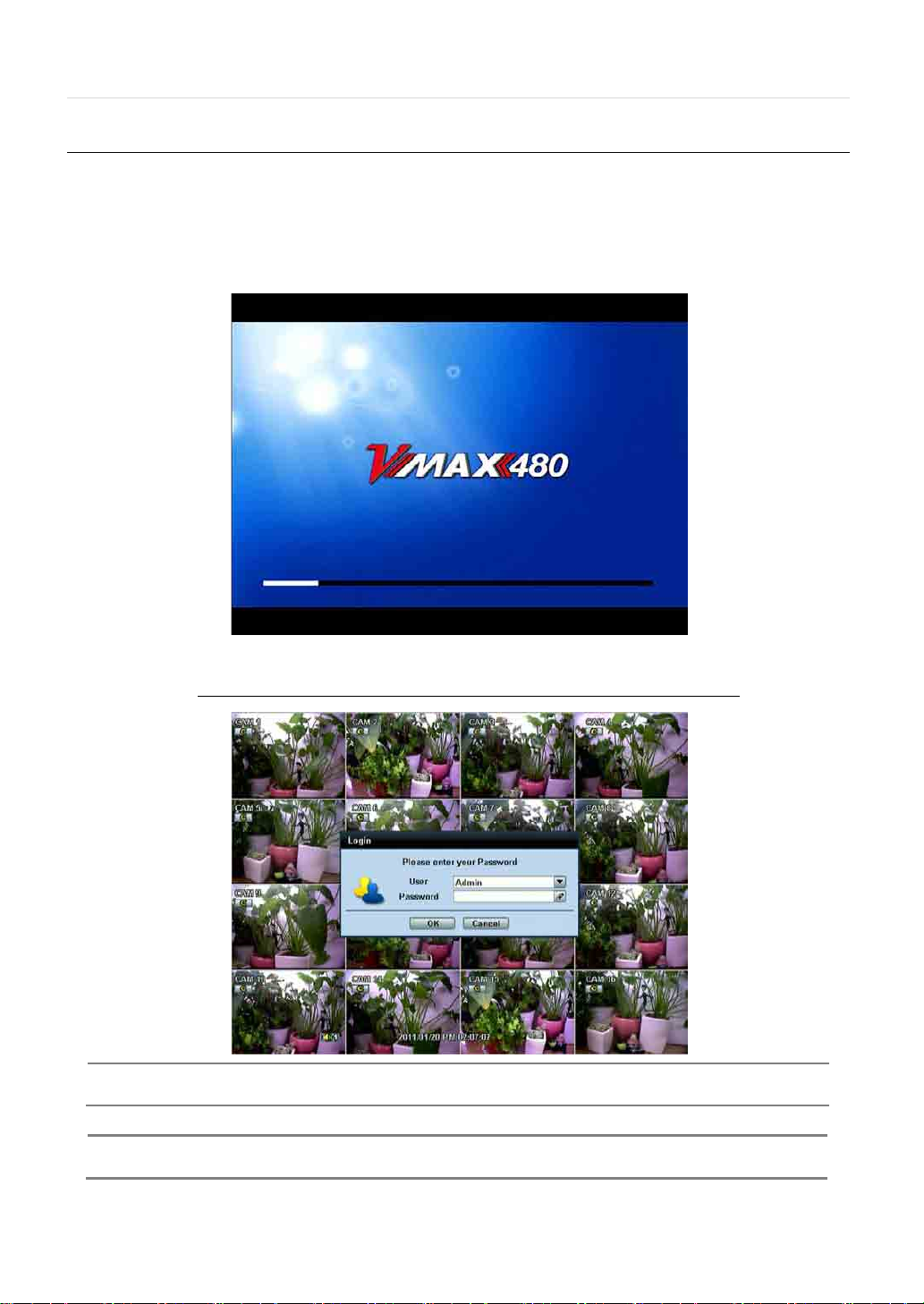
The boot-up screen will display as shown below. Please wait until the boot-up process completes.
When boot-up process completes, [LOGIN] Window will appear. Select the user name and enter the password.
Default Login is “admin” and the password box is blank a then press [OK] or Enter button
OTE
OTE
When changing the administrator (admin) password please make a note of it in safe place.
If you forgot your password contact your distributor, proof of purchase is required.
A mouse is included. In case you need to replace it, it is highly recommended to choose a well-known brand, such as
DELL, MICROSOFT, LOGITECH, or SAMSUNG.
Page 10
9 | Chapter 1 : DVR User Manual
N
End time. Once the times are set, click the [START] button to start the backup process.
Press to start playback in forward mode; press again to Pause the playback
or Press and Hold for instant playback of last video
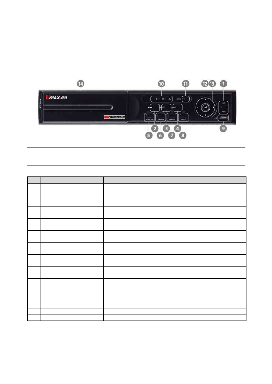
1.4 Front Panel
Dimensions of 8 & 16 channels DVR Case 11.80” W x 2.16” H x 12.46” D
Front panel allows the user to operate the DVR without having to use t he IR remote or a mouse.
OTE
No. Buttons Functions
I- Backup (Instant Backup)
In playback mode, the user can press the [I-BACKUP] button on the frontal keypad to configure both Start and
1 Menu / Exit Toggles On or Off Menu Setup Display
2 Fast-Reverse Button Search recorded video in the reverse mode up to 32x
3 Play / Pause Button
4 Fast-Forward Butto n Search recorded video in the fast-forward mode up t o 32x
5 Search / Instant Play
B-Mark
6
Call Monitor (Press and Hold)
PTZ
7
I-Backup (Press and Ho l d)
Mode
8
Freeze (Press and Hold)
9 USB Port USB Port (Ver. 2.0) for Mouse Operation, Backup Device or Firmwar e Update
10 LED Indicator
11 Instant Record Start Emergency Recording
12 Enter Button Select Value or Setting
13 Directional Arrows Menu Setup Navigation / Change Display Mode / PTZ control
video
Search recorded video
recorded.
Bookmark recorded video
Display a camera Full Screen on the Spot Monitor
Control a configured PTZ camera
Start “Instant Backup" to a USB flash drive
Change the cameras display Mode 1-8 or 1-16
Pause a live video display
Indicate System Status
Power, Record, HDD, and Remote connection
Page 11

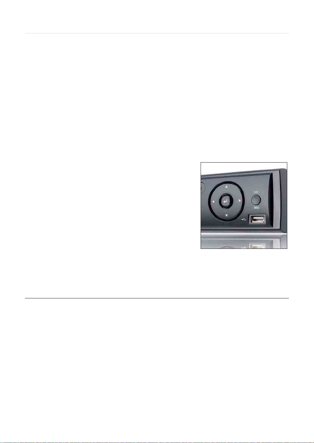
1.4.1 Directional Arrows:
1) Live Display & Playback Mode
Change channel number by using Left & Right Arrow buttons.
Change display mode by using up & down Arrow buttons.
2) Menu Setup
Use to select function at the menu setup display.
3) PTZ control (When PTZ button is pressed)
4) Zoom & Focus Mode (when PTZ button is pressed again)
Zoom in & Out by using Up & Down Arrow buttons.
Focus In & Out by usi ng Le ft & Right A rro w but ton s.
5) Call Monitor Mode (When call monitor is selected)
change the camera display in the full screen mode of spot monitor by using the Up & Down Arrow buttons.
1.4.2 ENTER Button
Select value or settings.
User Manual | 10
1.4.3 Menu /EXIT Button
T oggles On or Off the Menu Setup
1.4.4 MODE (Press Once) / FREEZE (Press and Hold) Button
Change camera display mode 1-8 or 1-16 and
Press and hold to Pause live video display.
1.4.5 PTZ (Press Once) / I-BACKUP (Press and Hold) Button
[PTZ] (Press Once): Press once to change to Pan & Tilt Mode. Use the [Directional Arrows] button to control Pan & Tilt function.
Press [PTZ] button again to change to Zoom & Focus Mode. Use the [Directional Arrows] button to adjust Zoom & Focus.
I-BACK UP (Press and Hold): To start Instant Backup Mode to a USB flash drive
1.4.6 INSTANT REC (Press Once) Button
INSTANT REC (Press Once): To start Emergency Recording Mode
1.4.7 B-MARK (Press Once) / CALL MON (Press and Hold) Button
B-MARK (Press Once): For bookmark recorded video
Press and Hold to activate the Call Monitor function:
Used to display a full screen video of a selected spot out channel. During Call Monitor Mode, click [CLOSE] button at the
bottom of the numeric panel to return to the previously programmed spot out mode.
Page 12

11 | Chapter 1 : DVR U ser Manual
1.4.8 SEARCH (Press Once) / INSTANT PLAY (Press and Hold) Button
SEARCH (Press Once): To search for recorded videos by date and time
INST ANT PLAY (Press and Hold): To start Instant Reverse Playback
Refer to [OPERATION > SEARCH RECORDING IMAGE] for a detailed image searching method.
1.4.9 IR Sensor Window (Remote Control Receiver)
T o receive input signal from the IR Remote Control
Page 13
NOTE
N
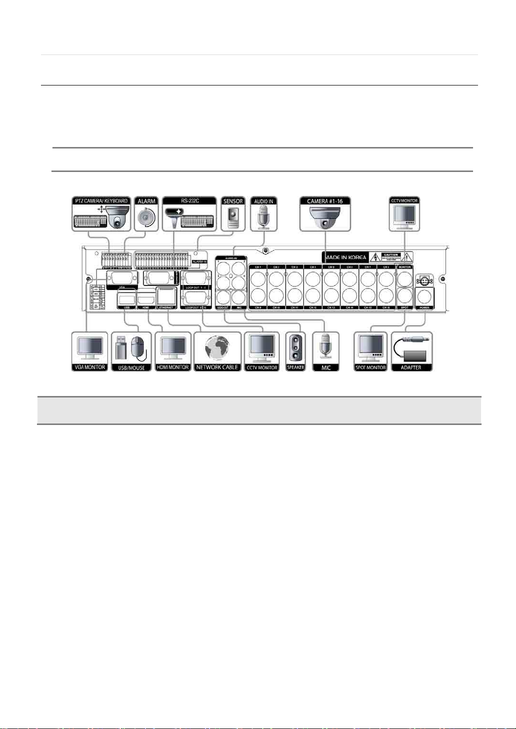
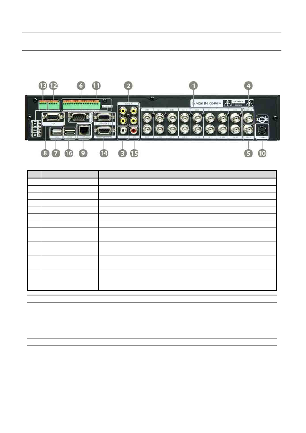
1.5 Rear Panel
Dimensions of 8 & 16 channels DVR Case 11.80” W x 2.16” H x 12.46” D
User Manual | 12
No. Name Description
1 Video-In Camera inputs (Supports NTSC/PAL)
2 Audio-In Audio Input Device (with Amplifier)
3 Audio-Out Audio Output Device (with Amplifier)
4 Video-Out Main Composite Monitor Output
5 Spot-Out Spot Composite Monitor Output
6 RS-232 Port RS-232 Input Device (POS)
7 USB Port USB Port (Ver 2.0) for Mouse Operation, Backup Device, or Firmware Update
8 VGA Port VGA Monitor
9 LAN Port 100Mbps RJ45 Ethernet Connection Terminal
10 Power Input Power Connection for 12 vDC at 6.67Amps Power Supply
11 Sensor Input Sensor Input
12 Alarm Output Alarm Output
13 RS-485 Port PTZ Dome Camera or External Keyboard Controller connection
14 Loop Out Loop Out Port
15 MIC-In MIC input device
16 HDMI Port HDMI Output
Carefully check whether the specifications of the peripheral devices match the DVR’s specifications.
1.5.1 Video-In
T o connect the camera input to the corresponding channel marked on rear panel
OTE
Camera input voltage level is 1Vp-p±10%.
1.5.2 Audio-In
T o connect audio input
1.5.3 Audio-Out
T o connect audio output
Page 14

13 | Chapter 1 : DVR U ser Manual
N
N
OTE
Use of audio output with an amplifier is recommended!
1.5.4 Video-Out
To connect Main composite monitor
1.5.5 Spot-Out
To connect composite Spot Monitor
1.5.6 RS-232 Port
RS-232 Input Device (POS)
1.5.7 USB Port (Version 2.0)
1) T o backup recorded video, using a USB flash drive (USB Memory Stick or USB HDD)
2) T o upgrade the firmware
3) To connect a mouse for system navigation
1.5.8 VGA-Port
T o connect a VGA Monitor
1.5.9 LAN Port
To connect RJ-45 jack for Ethernet connection
Consult net work a dmi nistr at or or the int erne t service provider for proper network setting.
1.5.10 Power Input
After connecting peripheral devices such as cameras, monitors, and a mouse to the DVR, connect the 12vDC power supply to
the power jack on the rear panel of the DVR.
1.5.11 Sensor Terminal Block
Connect sensors.
1.5.12 Alarm Terminal Block
Connect various alarm devices controlled by relay output.
OTE
Support both N/O (Normal Open) and N/C (Normal Close) type of sensors. If connected sensor is not functioning, ensure
The connection method may differ according to the type of PTZ controller. Enquire to your vendor for guidance.
1.5.13 RS-485 Terminal Block
Connect RS-485 cable for the control of PTZ camera or external keyboard controller.
Page 15

1.5.14 Loop Out
Loop Out Port
1.5.15 MIC-In
T o connect MIC input de vice
1.5.16 HDMI Port
T o connect HDMI device
User Manual | 14
Page 16
15 | Chapter 1 : DVR U ser Manual
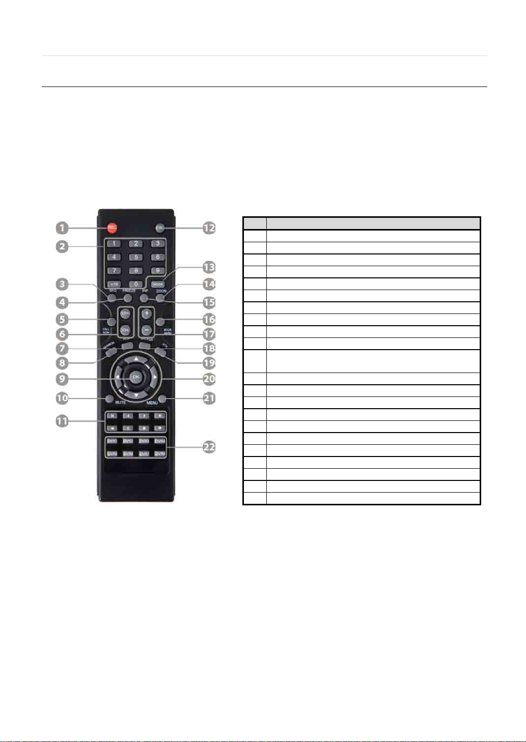
1
Instant (Emergency) Recording Button
2
Numeric Button
4
Freeze Button
5
Call Monitor Button
6
Channel Selection Button
9
OK (Select) Button
10
Audio Mute Button
12
Exit Button
13
Display Mode Button
14
Zoom Button
17
Zoom In & Out Button
18
Backup Button
19
PTZ Button
20
Direction Button (Up/Down/Right/Left)
21
Menu Button
22
ID Select Button (DVR1 ~ DVR8)
1.6 IR Remote Controller
The IR remote control allows the use to operate the DVR without having to use the mouse or the front panel buttons.
To use IR Remote Controller , the ID of the IR Remote Controller must be same as the ID of the DVR.
Default ID # for DVR and IR Remote Controller is “1”.
If you have more than one DVR, you can use one IR remote to control each DVR by setting a unique ID for each DVR.
No. Functions
3 Auto-Sequence Button on Live Display Mode
7 Instant (Emergency) Playback Button
8 Search Button
Playback Button on Search Mode
11
(Fast Backward/Playback/Stop/Fast Forward)
15 PIP Mode Button
16 Bookmark Button
Page 17
User Manual | 16
N
2 OPERATION
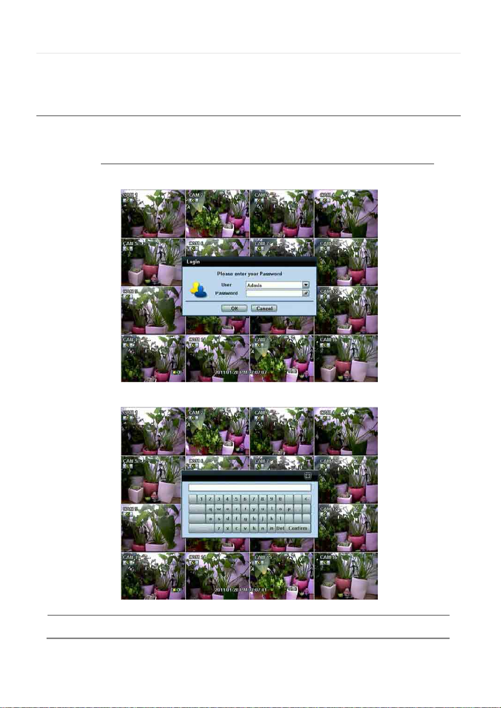
2.1 User Login
The DVR has various configurations. The administrator can set the system password and can prevent the User(s) from making
unauthorized changes to the configurations or recorded video
Default Login is “admin” and the password box is blank a then press [OK] or Enter button
Using the virtual keyboard to enter the password if required
OTE
1) [LOGIN] window will display on the monitor, until user logs in with the correct [User] and [Password].
2) If the system is set as [Auto Log-In], DVR does not require login. Refer to 4.1.2 User for details.
Page 18
17 | Chapter 1 : DVR U ser Manual
N
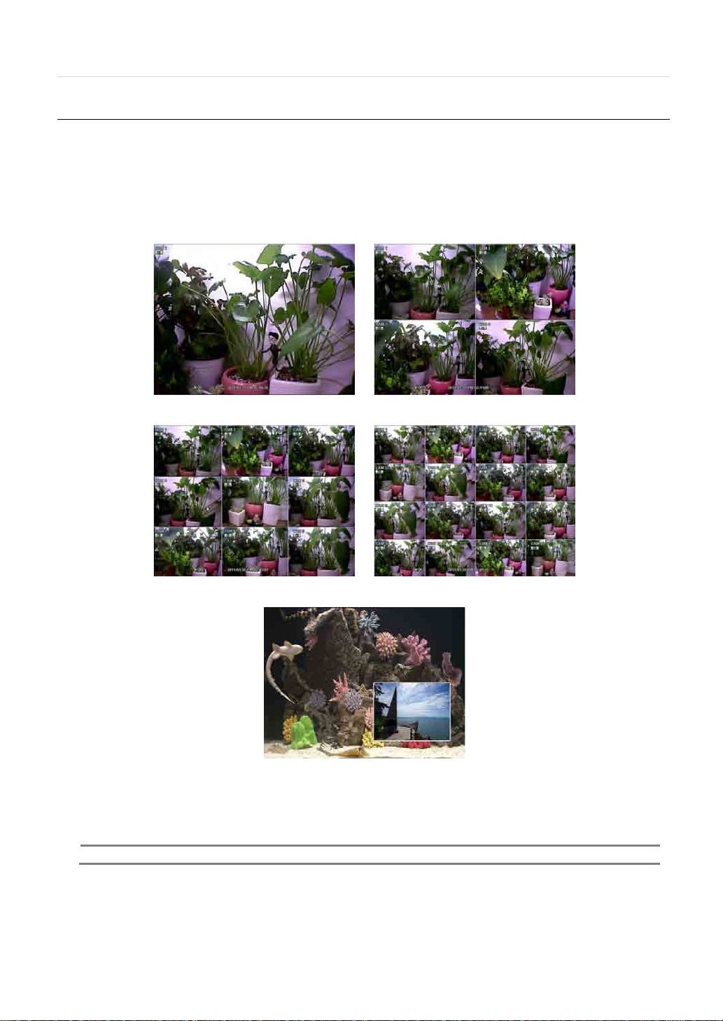
2.2 Live Display Mode
2.2.1 Channel Selection
After the cameras are connected, the real-time display mode is controlled through an easy button operation.
The images can be seen on real-time by 1, 4, and PIP screen. Press the Up & down Arrow buttons on the front panel or IR
remote controller to change the display screen sequentially .
[1 Channel] [4 Channel]
[9 Channel] [16 Channel]
[PIP Mode]
T o select a channel by mouse, place the cursor on the desired channel and click the left mouse button. To return to previous
screen mode, click the left mouse button again.
OTE
To select a channel using the mouse, the user is required to perform a slow and clear click of the left mouse button.
Page 19
User Manual | 18
Administrator user can set different level of authorization for each user. If a certain user is not allowed to view a certain live and
playback channel, then no image appears on the display screen. Refer to 4.1.2 User for details on how to setup.
When a camera is disconnected, an alarm sound will be activated depending on the system settings.
Page 20

19 | Chapter 1 : DVR U ser Manual
Recording
Activating Recording
2.2.2 Icons Description
Icon Shown on Upper Right Corner Icon Shown on Bottom Right Corner
Continuous Recording
Motion Detection Recording
Sensor Activating Recording
Continuous+ Motion Recording
Continuous + Sensor Activating
Recording
Motion Detection + Sensor Activating
Continuous + Motion Recording + Sensor
Emergency Recording
Audio Channel
PTZ Camera
No HDD, Smart Alarm & HDD Failure
Using PTZ
Showing sequence mode
Showing digital zoom mode
Page 21

User Manual | 20
N
2.2.3 Toolbar
Move the mouse cursor to the bottom of the screen monitor during live mode and the menu bar will appear instantly, as shown
below.
Instant Emergency Recording, which is useful to start recording when the user notices an unusual activit y . In emergency
recording, the system follows the [Panic Record] settings. The default settings for panic record is 30(25)fps @ CIF Resolution for
all channels. If you want to change the panic record settings for each channel, please go to [RECORD Panic Record].
To activated PTZ control, user can adjust the pan/tilt/zoom by moving the mouse pointer , like a virtual joystick.
Click the button to playback the most recent video clip automatically.
Display of the HDD usage. If it shows 60%, 60% of the HDD space has been used for recording.
OTE
If you do not see any colored icon on the top right corner of the live screen mode; then, it means that the system is not
recording any image. In this case, you need to check the [Recording Schedule] or [Camera] of the main setup menu.
Or the Display can turned OFF in the display system setup
Page 22

21 | Chapter 1 : DVR U ser Manual
2.2.4 Pop-up Menu
Place the mouse cursor anywhere on the screen and click the right button of the mouse to display the popup menu as shown
below.
When [SEQUENCE] is selected, icon is shown on the bottom right corner of the screen, and the display screen will
be changed sequentially.
When [ZOOM] is selected, digital zoom function is activated, and icon is shown on the bottom right corner of the
screen. The [ZOOM] function is only available on full screen mode. In the zoom popup mini-screen, the user can use the mouse
to drag a yellow box to the desired area of the camera to zoom. To return to Live display mode, click [ZOOM] again.
ZOOM Popup
Mini Screen
Page 23

User Manual | 22
2.3 Freeze Mode
Press [FREEZE] button on the front panel; or click the right button on the mouse when viewing a live image and select the
[FREEZE] option on the pop-up menu. In the Freeze mode, the image pauses; the date/ time information does not; and the
system clock continues running. Press [FREEZE] to pause the live view. To resume the live view, press [FREEZE] again, or click
the right button on the mouse and select the [FREEZE] option.
Page 24

23 | Chapter 1 : DVR U ser Manual
2.4 Call Monitor Operation
Press the [CALL MON] button on the front panel, or click the right button on the mouse and select the [CALL MONITOR] option
in order to enter Call Monitor Control mode. The numeric panel will pop up at the center of the screen.
Click the spe cific chann el butt on on the numeric panel to display full screen mode out of assigned spot out channels.
• Press the [CLOSE] button on the bottom of the numeric panel to go back to the previously programmed Spot Monitor
mode.
Page 25

User Manual | 24
NOTE
2.5 PTZ Operation
User can go to PTZ mode by clicking right but ton of mou se and sel ecting [PTZ CONTROL] in the pop-up menu as shown below
or by selecting the button on the menu bar located on the bottom of the main screen.
In PTZ mode, user can control PTZ operation with USB mouse.
While pressing the left button of mouse, user can drag the mouse pointer to up/down or left/right to move pan/tilt position of
the camera. If user moves the mouse pointer far away from the center position of the main screen, the PTZ camera moves at
faster speed. The user can also zoom in/out by rolling the wheel of mouse up or down.
Full PTZ functions are available by using USB mouse, IR remote control, or keyboard controller.
For focus control in PTZ screen mode, the user can right-click using the mouse to get the pop-up menu as shown below. Default
mode is to [ZOOM]. The user can select [FOCUS] to switch the wheel function of mouse from zoom in/out to focus. This will
change the default behavior of the mouse wheel.
Page 26

25 | Chapter 1 : DVR U ser Manual
N
C
or control focus within the interval time required by the DVR. In this case, it is rec om mended to increase
The user can also select the [PRESET], [GUARD TOUR], or [EXIT PTZ CONTROL].
OTE
User will see numeric pad t o select Preset number . The preset i s defined by set ting a PTZ prot ocol in the set ting menu .
The maximum number of preset is 255, but the max supported by the PTZ may be less.
User can autom ati call y swit ch PTZ camera positions to the defined preset settings by using [GUARD TOUR] function. The
connected PTZ camera mu st sup port touring functions. [GUARD TOUR] on the pop-up menu is only enabled when the PTZ
camera channel is changed to full screen. Please make sure that PTZ camera setting is correct; otherwise, [GUARD TOUR] is
shown as disabled.
AUTION
Depending on PTZ cam era, some preset positions might be skipped if, for example, the PTZ camera cannot move
mechanically
the interval setting to a value that allows cameras to finish its Pan & Tilt.
Page 27

User Manual | 26
2.6 Instant Playback of Recorded Video
T o play a recorded image, press the [PLAY] button from the Front Panel or IR Remote Controller.
It is easy to use the USB mouse to playback recording files. The recorded files can be played backwards or forwards. Press the
[REWIND] and [FAST FORWARD] buttons, and the playback speed can be controlled in steps of 2, 4, 8, 16, 32 times the
real-time when playing backwards or forwards.
User can click the button to play the latest video clip automatically.
In playback screen, user can utilize various playback modes, make an instant manual backup (archive), go to calendar search
mode, change channel, and change screen modes. By clicking the left mouse button in the colored-time bar, the user can jump
to a different time in the recording. In addition, user can move the vertical search bar by dragging the bar back and forth and
releasin g it to search the desired time in detail.
[Playback Screen]
Page 28

27 | Chapter 1 : DVR U ser Manual
NOTE
2.7 Clean Button During Playback
De-interlacing feature is required for smooth playback of video that is recorded in D1 (720x480/576) re sol ution.
In playback mode, user can press [CLEAN] icon at the menu bar located in the bottom of the main screen. After clicking [CLEAN]
icon, a blue circle forms around the icon, which means de-interlacing has been activated. After changing to de-interlacing mode,
press the pause and step forward icon. User can get a better image as shown below. Click [CLEAN] icon again to in activ ate th is
function.
[De-Interlace Image] [Interlace Image]
The De-interlacing feature by pressing the [CLEAN] icon can be activated only during a full screen mode.
Page 29

User Manual | 28
N
2.8 I-Backup (Quick Backup During Playback)
Press [floppy Icon) and Connect an appropriate USB flash drive and press [SCAN] button to get the system to recognize the
device before archiving. Necessary file size will be shown before burning.
Users ca n ch eck the [A UTO PLAYER] box to include the viewer file. This function allows the user to play the video clip without
having to install the software on the computer . Otherwise, the file backup format will be in the Manufacturer’s Proprietary Format
(PSF). ACS (Advance Client Software) Backup Player is required.
Once the backup completed press [OK] or [Enter]
OTE
The [HELP] button will help you understand how to setup several important settings. For example, if you need help on
how to use the Backup function, click [HELP] button at the right bottom of the [BACKUP] menu.
Page 30

29 | Chapter 1 : DVR U ser Manual
2.9 Search Recording Image
2.9.1 Date/Time Search
Select [Date/Time] in Setup Menu to search for a certain file within the recorded video data.
The calendar displays dates with recorded video data in RED color. Click one of the desired dates in Red. Then, the recorded
data for the selected date will appear .
Once the recorded video data of the selected date appears, user can adjust the vertical search line to the time that user wants to
search by dragging the mouse. As the vertical line is moving back and forth, user can see that the clock is changing
simultaneously. Move the vertical line to the time you wish to play . Click [PLAY] button to play the selected video data.
The colors of the time bar are different, depending on the recording mode.
Page 31

C
NO Color No Recording
The DVR does not record, even though user sets a MODE of recording in [RECORD SETUP] tab.
RED Color
Panic Recording
YELLOW Color
Continuous Recording
The DVR records all the time for the set camera(s).
GREEN Color
Motion Detection Recording
The DVR only records when it detects motion.
Users can also set motion record configuration in the [MOTION ALARM] tab.
If user sets the [MOTION ALARM] tab to [OFF] and sets the [SCHEDULE] tab to [MOTION], the
system will record when motion is detected but not activated.
ORANGE Color
Sensor Activated Recording
The system records when a sensor is triggered only during the dwell time as set in [SENSOR] of
the [DEVICE] menu.
If user sets [SENSOR] tab to [OFF] and sets [SCHEDULE] tab to [SENSOR], the system will not
record even though a sensor is triggered.
SKY BLUE Color
C + M (Continuous + Motion Detection) Recording
The DVR records continuously but will switch to the motion configuration specified in the [MOTION
ALARM] tab of the [DEVICE] menu, if motio n is detected within the motion area. The system will
also send a Motion Event Message to the Advanced Client Software over the network.
If user sets [MOTION ALARM] tab to [OFF] and sets [C + M] in the [SCHEDULE] tab, the system
will always record as Continuous Recording even though the DVR detects a motion within the
motion area.
DARK ORANGE Color
C + S (Continuous + Sensor Activated) Recording
The DVR records continuously but will switch to the sensor configuration defined in the [SENSOR]
tab of the [DEVICE] menu, if a sensor is triggered during dw e ll time. The system will also send a
Sensor Event Message to the Advanced Client Software over the ne twork.
If user sets [SENSOR] tab to [OFF] and sets [C + S] in the [SCHEDULE] tab, the system will record
as Continuous Recording even though a sensor is triggered.
PINK Color
M + S (Motion Detection + Sensor Activated) Recording
The DVR records when motion is detected or when a sensor is triggered according to the [DEVICE]
menu settings.
If user sets the [MO TION] and [SENSOR] tab of the [DEVICE] menu to [OFF], the DVR will neither
record nor notify the Advanced Client Software or Central Management System.
PURPLE Color
C + M + S (Continuous + Motion Detection + Sensor Activated) Recording
The system records continuously but will switc h to the motion configuration when motion is
detected or the sensor configuration when a sensor is tr iggered.
AUTION
Dark Blue Color
A Dark Blue Color in the -Search Bar during playback mode indicates data recorded during DST (Daylight Savings Time).
User Manual | 30
Page 32

31 | Chapter 1 : DVR User Manual
N
2.9.2 First Data
Go to the first screen of the recorded videos. This is the oldest recorded video.
2.9.3 Last Data
Go to the last screen of the recorded video. This is the most recent recorded video.
2.9.4 Event Log
The Event Log Search finds particular events, quickly and easily.
Click button to playback the selected event data.
Copy the event list t o a U SB me mory dev ice in text fi le f or mat. Insert the USB Memory Stick into the USB Port. Press [SCAN]
button to dete ct th e USB s tick and then press [EXPORT] to copy the log information to the media.
T o see a particular event, click the arrow buttons on the Front Panel or Remote Controller to the desired time range.
The following are the categories indicated on the Event Viewer .
1. Alarm by Sensor
2. Alarm by Motion
3. Alarm by Video Loss
4. Alarm by HDD Full
OTE
If the Alarm does not activate even after the alarm input setting has been made, check the a l arm
connection port of the DVR rear panel.
Page 33

2.9.5 System Log
The System Log Search finds particular system log information, quickly and easily.
User can copy this event list to USB memory device in text file format.
User Manual | 32
Once export is completed, the user can find a folder titled with the exported date created in the USB thumb drive .
There is [system.log] file stored in the folder.
Page 34

33 | Chapter 1 : DVR User Manual
N
N
The following are the categories indicated on the system log viewer.
1. Log by System
2. Log by Setup
3. Log by Network
OTE
Each page of the [System Log] and [Event Log] Window displays 20 logs. User can view the next set of logs on another
page by clicking the arrow icons.
2.9.6 Bookmark
Go to the bookmark list to search the recorded video data in the bookmark list. Users can make their own bookmark list simply
by clicking button during playback. When you do bookmark search, you can easily playback the bookmarked video by
clicking button located right next to the list.
OTE
User can press [SEARCH] button on the front panel to get the [BOOKMARK SEARCH] pop-up menu as
shown above. Use the front panel key buttons to control this menu.
Page 35

User Manual | 34
2.10 DST Setting and Screen Saver
DST starts at 2:00 local time on 2nd Sunday of March, and ends at 2:00 DST on 1st Sunday of November.
During DST (Daylight Saving Time), the DVR time clock adjusts to the regional time zone. The clock will shift by one hour after
the DST settings start and will delay by one hour after DST fi ni s he s.
T o make DST setting on the DVR, go to the menu [SYSTEM > SYSTEM INFO] and click [DATE/TIME]. User can setup DST
“Begin & End” time afte r chec king [USE DST] box.
When you return to search mode, you can clearly see there is no data in all channels for one hour, since the clock jumps from
2:00 to 3:00.
The clock jumps backward to 1:00 standard time on 1
When DST finishes, there will be an hour of overlapped video. A Blue color indicates the overlapped video in the Search Bar
during playback mode.
st
Sunday of November.
When user clicks on the overlapped video data, a message titled [Recorded Video Selection] will pop up. The user can then
select whether to play DST Data or Non-DST Data. Click [OK] to play DST image. Click [CANCEL] to play Non-DST image.
Page 36

35 | Chapter 1 : DVR U ser Manual
[DST Image]
[Non-DST Image]
Page 37

User Manual | 36
N
T o set a screensaver on the DVR, go to the menu [S YSTEM > SYSTEM INFO] and click [SC REEN SAV ER] to get the Screen Save
window as shown below. Users can select [CRT] and/or [VGA] by checking the boxes. Users can set the WAITING TIME for
when the monitor will automatically turn off.
OTE
WAITING TIME: Users can select the [WAITING TIME] from NONE,1,2,3,4,5,6,7,8,9,10,20,30,40,50, and up to 60
MIN. The screen saver will not work when either WAITING TIME is set to “NONE” or both SPOT and VGA checkbox are
unchecked. Screen saver may not work, during system upgrade, HDD format , or data backup process. The system
continues to record while the monitor is turned off.
When it comes to the [AUTO LOG O FF] setting, refer to the USER setting.
Page 38

37 | Chapter 1 : DVR U ser Manual
3 SETTING
General setting structure consists of System, Device, Record, Network, Backup, and Quick Setup as shown below.
[SYSTEM] [DEVICE]
[RECORD] [NETWORK]
[BACKUP] [QUICK SETUP]
Page 39

User Manual | 38
Main Menu Sub Menu
SYSTEM INFO
USER
SYSTEM
DEVICE
RECORD
NETWORK
BACKUP MANUAL BACKUP
QUICK SETUP QUICK SETUP
EXPORT/IMPORT
HDD
FACTORY DEFAULT
CAMERA
AUDIO
SENSOR
MOTION ALARM
EXTRA ALAR M
PTZ
RECORD SETUP
PANIC RECORD
SCHEDULE
HOLIDAY
NETWORK
DDNS
NOTIFICATION
Page 40

39 | Chapter 1 : DVR U ser Manual
N
CS), or Central Management System (CMS), as a Time Sync Server in
3.1 System
The Menu button is selected by clicking [TOOL] on the menu bar or clicking the right mouse button.
Users can move mouse pointer from [SYSTEM] to [QUICK SETUP] to instantly look around the sub-menus on the menu screen.
Using the left mouse button, the user can select a desired category for editing.
3.1.1 System Info
[Date/Time] / [VGA Resolution] / [Language] / [IR Remote Id] / [firmware Upgrade] / [Video Signal format] / [IP Address]
[Mac Address] / [Keyboard controller Id] / [Keyboard Type] / [Baud rate] / [K eyboard Beep option] / [NTP] (Network Time
Protocol) / [Display] / [Screen Saver] / [Default]
OTE
There are two types of TIME SYNC MODE.
1) Server Mode
The operating DVR is set as a Time Sync Serve r, which can synchronize the time c lock o f another DVR(s) co nnec ted
er the same network environment.
2) Client Mode
IP Number of designated DVR, Advanced Client Softwar e
[SYNC SERVER]; and then its time clock is
setup time in [S YN C C YC LE ] .
Mac address is a unique network identification number for each system.
NTSC/PAL is automatic; make sure the cameras are connected to the DVR before turning the power on of the DVR.
Page 41

User Manual | 40
P
Remote ID:
Keyboard ID:
The Remote ID should match the ID of the IR Remote Controller in order for the remote to function.
The Keyboard ID should match the selected DVR on the keyboard. In addition, the baud r at e and Keyboard
should match the selected keyboard controller.
Upgrade:
Users can easily upgrade the DVR via DVD, CD, USB, or FTP Server.
ROCEDURE
How to upgrade system firmware by using USB memory stick
1) Insert the USB th um b-drive formatted by FAT32 in any USB port of DVR (compatible with USB 2.0).
2) Press the [SCAN] button and the brand or model name of the USB will display on the [DEVICE] field.
3) Click [OK] to confirm.
How to upgrade system firmware by using FTP server
1) Select FTP in th e d rop-down list and type the given FTP server IP address in the [HOST ADDRESS] field. There
is no default username and password. The FTP server address is subject to change without prior notice.
2) Click [CHECK] button. DVR will detect the latest Firmware version from the FTP server. If there is a new
firmware, DVR will ask if you want to upgrade it or not.
3) Click [OK] to confirm it and then click [START] to start upgrading.
Page 42

41 | Chapter 1 : DVR U ser Manual
C
N
AUTION
Click the [DISPLAY] button to set Status Display Time Out, Setup Menu Time Out, Sequence Mode Interval, PIP Interval, Spot
Monitor Interval, and Transparency.
[TRANSPARENCY] is the transparency level of the menu screen. 0% means no transparency at all.
It is recommended to format the HDD after finishing the firmware upgrade because the data recorded by previous
firmware may cause malfunction of DVR due to the difference in format.
It is possible to send the system firmware back to factory default. This may be useful if some of the functions do not
work properly after a firmware upgrade. It is highly recommended to check all functions and menus after a firmware
upgrade for proper layout and performance.
You may hide or unhide Live or Playback Status Display by checking the box.
OTE
DVRs support the following video resolutions: 800x600, 1024x768, 1280x1024, 1280x720, and more.
User must set the proper resolution according to the monitor resolution.
Page 43

User Manual | 42
N
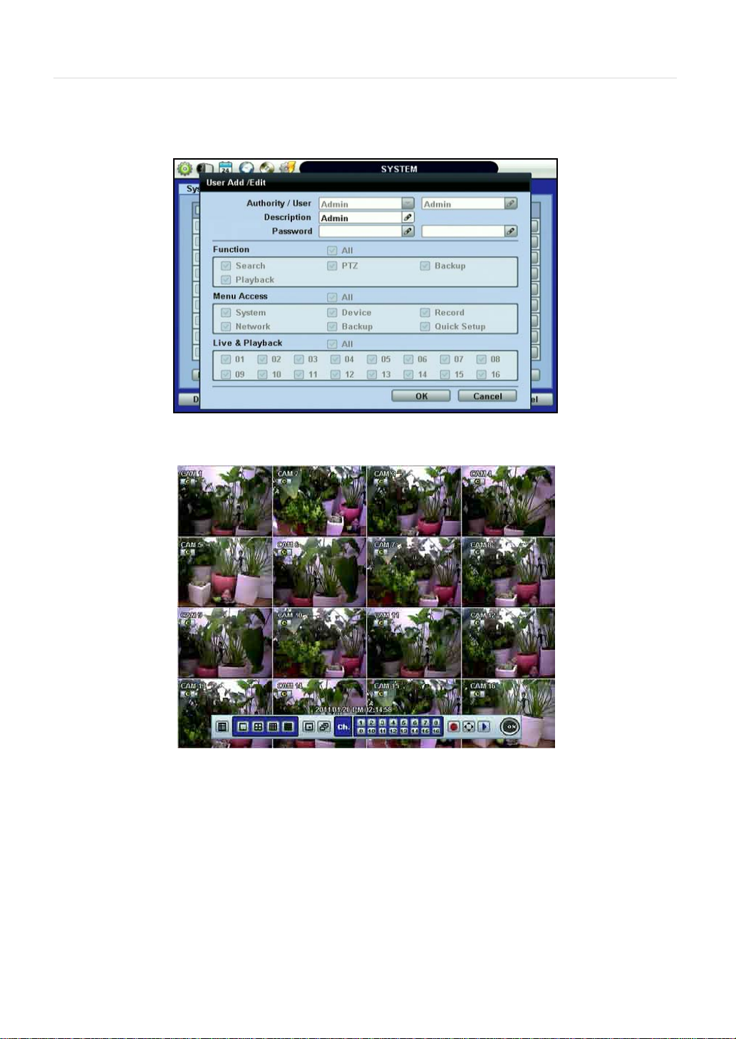
3.1.2 User
“Admin” with no factory default password is always the main user of the DVR. Admin should change the password of the DVR for
extra security.
Admin can add new users with different permi ss ion lev el s in areas of Function, Menu Access, and Live & Playback.
[FUNCTION] consists of Search, PTZ, Backup, and Playback.
[MENU ACCESS] consists of System, Device, Record, Network, Backup, and Quick Setup.
[LIVE & PLAYBACK] consists of the different camera channels.
OTE
The DVR can be set so user does not lock or require login.
If user checks [ON BOOT], DVR will not ask for an ID and Password input when the system reboots.
If user sets a time for [AUTO LOGOUT], the DVR will automatically go to the live display mode. To control the DVR again, user
has to input the ID and Password.
Each DVR can have up to 9 users, including the Administrator.
Page 44

43 | Chapter 1 : DVR U ser Manual
3.1.3 Export/Import
Users can copy and paste the system configuration values in this menu.
[EXPORT] enables user to copy the settings for the DVR to any USB memory devices.
[IMPORT] enables user to recall the settings saved from other systems using CD/DVD/USB memory devices. During the import
process, make sure that the firmware version of source DVR is the same as the destination DVR.
Select [EXPORT] or [IMPORT] option. Select which system configuration values to export/import. Click [SCAN] to find a device
connected to the system and click [START] to begin the process.
Page 45

3.1.4 HDD
[HDD] tab displays the HDD information. SAT A HDD is used for the VMAX480.
HDD Full
: When HDD is full, the DVR can overwrite old data or stop recording. Check [OVERWRITE] or [REC STOP].
User Manual | 44
HDD Clear
click [HDD Clear] button.
The maximum number of built-in HDD units varies across DVR models.*
Health: Click the [CHECK] button below Health to view the [Health Check] window. [Health Check] displays the model, size,
temperature, and lifetime of the HDD.
: This button is used to format a new HDD or an existing HDD. Check the box next to the DVR you wish to format and
Page 46

45 | Chapter 1 : DVR U ser Manual
N
N
If system resources are busy with task, such as making a network connection or performing video playback during the format
process, the format may fail. If the format fails, reboot the system resources and then try to format again.
[Format Completed]
OTE
1) Formatting may take around 2 minutes for 250GB, 3 minutes for 500GB, or 4 minutes for 750GB.
2) The system always reserves a maximum of 5GB of space in each built-in HDD to uti liz e
The memory for archiving effectively
.
3.1.5 Factory Default
With an authorized password, users can get the system back to factory default configuration.
OTE
Once the user clicks the [START] button and enters the admin password, all the configuration values made by the user
system settings will be sent to factory defaults, but the recorded video data will not be erased.
Page 47

User Manual | 46
3.2 Device
The [DEVICE] button consists of the following submenus: Camera, Audio, Sensor, Motion Alarm, Extra Alarm, and PTZ.
3.2.1 Camera
The [CAMERA] tab enables user to change camera settings. Users can change Title, Covert, Brightness, Contrast, Color,
Sensitivity, Audio Mapping, and Motion Area Setting for each camera.
Covert: This function, also called “hidden camera,” hides camera display and playback as if there were no camera recording.
Covert applies to both Live and Playback View.
The default motion area setup is the entire camera area.
Page 48

47 | Chapter 1 : DVR U ser Manual
N
3.2.2 Audio
Users can selec t the audio input and outp ut during live displ ay and matc h the audio in put to a desi gnated cha nnel. (Please refer
to Section 4.3.1 Camera Record for more details.
User can raise or drop the volume by using the volume control panel.
OTE
User can listen to the audio on both live display and playback mode depending on the setting. In addition, user can listen
to the audio for both live display and playback mode through the network using Advanced Client Software (ACS), Central
Management System (CMS), and/or Internet Explorer web browser.
Page 49

C
N
N
N
3.2.3 Sensor
User Manual | 48
• Type: Select from [OFF], [N.O], and [N.C].
• Cam: Select the associated camera.
• Notify: Click the down arrow button below Notify to select how to be alerted when a sensor is activated or a motion
is triggered. The system can generate a buzzer sound and/or popup the screen of the camera in alarm.
AUTION
• Preset: User can select which camera to move to a specific preset position, when a sensor is triggered. User should
setup the preset position. Look at PTZ Menu 4.2.6 for details.
Multi-preset can be set with a single PTZ camera, so users can cover a multi-preset zone with a single PTZ camera.
• Relay: Turn on or turn off the Relay Output.
• TTL: Turn on or turn off the TTL.
• Dwell Time: Set the time of recording when a sensor is activated. During the Dwell Time, cameras will record
according to the frame and alarm (relay) output set. The recording stops, and alarm output turns off when the dwell
time elapses.
OTE
OTE
OTE
Relay contact can handle up to 24V/1A of other devices. If connected to a circuit that is
Over 24V/1A, the system may experience problems.
[SENSOR] here means the alarm connected to the DVR, which is triggered by physical sensor input.
If the sensor does not operate properly, check the setting of the sensor type (N/O or N/C).
The alarm might not function if the actual connecting sensor type and the sensor type in the system setting are
inconsistent.
[CAMERA POP-UP] means that multi-screen live video mode will be switched automati cally to single chan nel mode, wh en
an alarm is triggered. This single channel video will be the channel triggered by alarm.
Page 50

49 | Chapter 1 : DVR U ser Manual
NOTE
3.2.4 Motion Alarm
[MOTION ALARM] records only when DVR S/W triggers motion detection within the defined motio n ar ea.
If user sets Intensive to [ON], the DVR records at the maximum recording speed upon motion detection. Video will record for
the selected post-alarm dwell time, and pre-alarm video will record for the specified time. The selected sensor-out channel send s
an alarm signal.
• Copy Settings: Upon pressing [COPY SETTINGS] button, the [COPY SETINGS] window will appear. Use this function
to copy the settings of a single camera to the other cameras. Se l ect the camera to copy from, the properties you
would like to copy and the sensor numbers to apply the settings to. Click [OK] button.
[Motion Alarm] here means alarm triggered by motion detection set by motion menu of DVR.
3.2.5 Extra Alarm
SMART is an alarm signal triggered when the HDD is about to be out of operation. SMART Alarm is created by the HDD and is
captured by the DVR. If the HDD does not create this alarm, then the DVR cannot capture and output the signal.
Users can set the percentage for HDD Usage. When Usage is set to 50%, DVR will notify the user with a camera popup or a
beep sound when the HDD is 50% full.
Page 51

P
3.2.6 PTZ
Full control of PTZ cameras is available in this menu.
Please refer to Section 3.3 PTZ Operation for details.
User Manual | 50
• PTZ Menu (Depending on the model of PTZ camera): If selected, the OSD menu of PTZ camera is imported and shown on
the DVR monitor allowing the user to control the full PTZ settings.
• Preset: 1 to 255 Presets are supported.
• Protocol: Select the proper protocol of the connected PTZ camera.
• Address: Set the PTZ driver address of the connected camera.
• Baudrate: Select baud rate level from 1,200bps up to 115,200bps.
• Check the below items for proper PTZ operation.
1 Check if the protocol of the connected PTZ camera is correct.
2 Check if the communication settings, including the baud rate, of the connected PTZ camera are in accordance with
the assigned value for that PTZ protocol.
3 Check if the address of the connected PTZ camera is correct.
4 Check if the wiring to the PTZ controllers are correct.
ROCEDURE
How to Setup PTZ Camera with Pelco-D Protocol (example)
1 Make sure the serial communication with the PTZ camera is through the RS-485 port.
2 Select [PELCO-D] at the protocol list, and set the address.
3 Select Baud Rate to be the same as the PTZ camera.
4 Click the [SAVE] button to confirm this configuration.
Page 52

51 | Chapter 1 : DVR U ser Manual
3.3 Record
Configure various record settings such as Continuous, Event, and Panic for each individual camera channel in the Record Setup
Menu. Network Stream settings are configured independently from the record settings in this menu as well. Therefore, the user
can optimize the bandwidth used by configuring the resolution, FPS, and image quality separately.
There are four sub menus in the RECORD menu—Record Setup, Panic Record, Schedule, and Holiday.
3.3.1 Record Setup
Configure record settings such as Resolution, FPS, Quality, Pre/Post Alarm, and Record Type for Normal Recording (Continuous)
and Event Recording (Alarm or Motion). Configure for each channel or use the [COPY SETTINGS] button to apply the same
settings to all cameras.
First, select the Record [Mode] for the camera channel.
Record Mode “C” (Continuous) disables Event Recording, and the DVR uses the settings for Continuous Recording.
[Continuous Record Setting]
Page 53

Record Mode “M” (Motion Detection) or “S” (Sensor/Alarm) uses the Event Recording Settings only.
User Manual | 52
[Event Record Setting]
Record Mode “C+M” (Continuous + Motion), “C+S” (Continuous + Sensor), or “C+M+S” (Continuous + Motion + Sensor)
simultaneously engages both Continuous and Event Recording Settings. DVR records with continuous record
settings, but when there is an event (Motion, Sensor , Alarm), the DVR records with the Event Record Setti ngs.
Select “Off” as the Mode to disable a specific camera from recording.
Select the record Resolution for each camera channel. The Resolution is applied to both Continuous and Event
Record Settings.
[
Resolution Setup]
[Resolution] is the required number of horizontal and vertical pixels in a frame (horizontal pixels x vertical pixels). Select from the
options: 352×240/288, 720×240/288, and 720×480/57 6. Def ault is 352×240/288 . Picture quality gets better , as the resolution
increases.
Page 54

53 | Chapter 1 : DVR U ser Manual
[FPS and Quality Setup]
Select the FPS (Frames Per Second) for each camera channel. The system automatically calculates [Remaining FPS] that users
can use.
Quality influences the “byte size per image.” When Quality is [Low], both image quality and size is lower. When Quality is [High],
both image quality and size is higher . Consider the necessary recording period, the importance of each camera image, and the
quality of the an alog sign al whe n set tin g the re cordi ng q ualit y.
Check the [Advanced] box for a more detailed record setup for each camera channel. When the box is checked, [SCHEDULE 1]
and [SCHEDULE 2] buttons appears.
The buttons are simply for two [Record Setup] pages. This enables user to set a combination of two schedules.
Page 55

User Manual | 54
N
N
N
of 352x240/288 (CIF) an d takes twice th e amount of stor age capac ity. When high resolution is selected f or the same period,
N
OTE
The maximum number of FPS is 480(400)FPS for the DVR. If the recording setting exceeds the limit while users setup the
Resolution and FPS, the popup message “Please check FPS setting.” will appear. Please setup the resolution and FPS again
based on the “Remaining FPS”.
COPY SETTINGS
OTE
Upon pressing [COPY SETTINGS] button, [COPY SETTINGS] window will appear. In this window, select the camera the u ser
wants to copy from. Select or deselect the p rop ert ies —Resolution, FPS, Quality, Pre Alarm, Post Alarm, and Type—to copy.
Select the camera channels to apply the settings to.
OTE
The storage capacity for the same image can be different depending on the resolution. 720x240/288 ( 2CIF) is twice the size
the high resolution takes up more storage, and its storage period can be shorter on the same hard disk capacity.
OTE
For the same resolution, frame per byte size will vary according to various reasons, such as the recorded picture quality
setting, movement, c omplexi ty of the image, and noise. Th erefore, the total recording period will differ greatly according to
the specific image conditions.
• 352×240/288 : Standard Quality Standard 1~5KB
• 720×240/288 : Standard Quality Standard 5~10KB
• 720×480/576 : Standard Quality Standard 10~20KB
Quality by 40(low), 60(standard) , 80(high), and 100(highest) makes frame size different by around 30% in each level.
Page 56

55 | Chapter 1 : DVR User Manual
Configure the Network Stream Settings independently from the Record Settings.
Click [LIVE STREAM] button. [LIVE STREAM] window will now appear, as shown below.
[LIVE STREAM] enables users to optimize data transmitted over the network by configuring the Resolution, FPS, and Quality
without affecting the Record Settings.
Users also have the option to configure Panic Record settings. The Panic Record Setting is intended to be used under emergency
situations.
T o use Panic Record, press the [INSTANT RECORD] button on the frontal keypad or click the button from the control
panel in live mode. For this record type, it is recommended to use maximum resolution, FPS, and quality.
Page 57

User Manual | 56
3.3.2 Schedule
Set the Recording Schedule. All Schedule is marked for recording as factory default. To cancel recording for a specific time, select
[CLEAR] button and click or drag the specific date/time.
When Advanced Setting is select [SCHEDULE 1], [SCHEDULE 2], or [ALL] button and click the specific date/time.
Page 58

57 | Chapter 1 : DVR U ser Manual
3.3.3 Holiday
Click [HOLID A Y ] tab to assi gn ho lid ays. Assig n a un iqu e sche dul e fo r holid ay s in the [SC HED ULE] t ab.
Page 59

User Manual | 58
N
3.4 Network
3.4.1 Network
The DVR has a b uilt -in web server.
• Network Type: Select network type. Select LAN for fixed (Static) IP or DHCP for dynamic IP.
If you select DHCP, click [IP DETECT] button to detect the network information.
• Subnet Mask: Clarifies the subnet that the system belongs to. Standard address is [255.255.255.0]. For more information,
please consult your network administrator or your internet service provider.
• Gateway: The IP address of the network router or gateway server. The gateway is required in order to connect throu gh th e
external router from the remote. For more information, please consult your network administrator or your internet provider.
• DNS Server: There are two DNS Server settings, one for the Preferred DNS and one for the Alternative DNS. To use the
internet, enter the IP address of the Domain Name Server (DNS) Server . This is provided by your internet service provider.
• [TCP-IP/Mobile Port] “Default is 9010”when connecting locally or remotely using Pc; Mac; or Mobile 3G or higher.
• Web Port: “Default is 80” when connecting using the Web Browser .
OTE
[TCP/IP Port/Mobile Port], and [Web Port] should all be different from each other.
Page 60

59 | Chapter 1 : DVR U ser Manual
• UPnP (Universal Plug and Play): UPnP stands for Universal Plug and Play, which indicates a universal protocol for
widespread plug-and-play devices to ease the network implementation. When the PC and DVR has the UPnP installed, t he
PC automatically begins to recognize the DVR in the same local area network. This way PC can directly connect to the DVR
by clicking on the icon representing the DVR in [My Network Places] folder . The first five characters of the detected DVR
filename is the firmware version.
Double click on the desired icon. The icon will open an internet explorer browser that connects to the DVR as shown below.
Please type in your User ID and Password and click [LOGIN] button. To connect to the DVR, click [CONNECT] button.
Default Login is “
admin” and the password box blank.
Page 61

User Manual | 60
N
N
N
• Auto Private IP Setup (NAT Tr aversal): The UPnP NAT T r aversal function will help to setup the DVR to c onnect to the internet via
a router.
When a PC connects to a DVR that is not in the same local area network, a real IPO Address and corresponding Port Number is
required. However , if the DVR is behin d a ro uter, the PC and DVR will communicate through the router . T o view images from the
DVR on your PC, the router will need to setup Port Mapping (Port Forwarding).
When UPnP NAT Traversal Function is enabled, the DVR will set the router automatically. To do this, check the [AUTO IP (NAT
TRAVERSAL)] box in the [UPnP] Menu.
OTE
OTE
OTE
The system transfers video images at real-time over the network even during no record.
For example, user can monitor live video even when motion has not occurred during motion detection mode.
If there is no physical network connection, it may take a few m inutes for the system to start working, since the network
configuration in DHCP mode and the DHCP connection cannot be made.
The maximum number of simultaneous connection is 10 users for each DVR using PC or Mac and 5 users
using Mobile devices.
3.4.2 DDNS
To use DDNS check [USE DDNS] box and input the following information.
[DDNS Server] is dwddns.Net or dyndns.com. ([dwddns.Net] is recommended)
[TCP/IP Port] Default is “80”
[DVR Name] can be the business name or location and press Start to make sure the DVR Name is available.
To connect using the web browser type
[ID] and Password is required when using dyndns.com
http://dvrname.dwddns.net
 Loading...