

Page 1
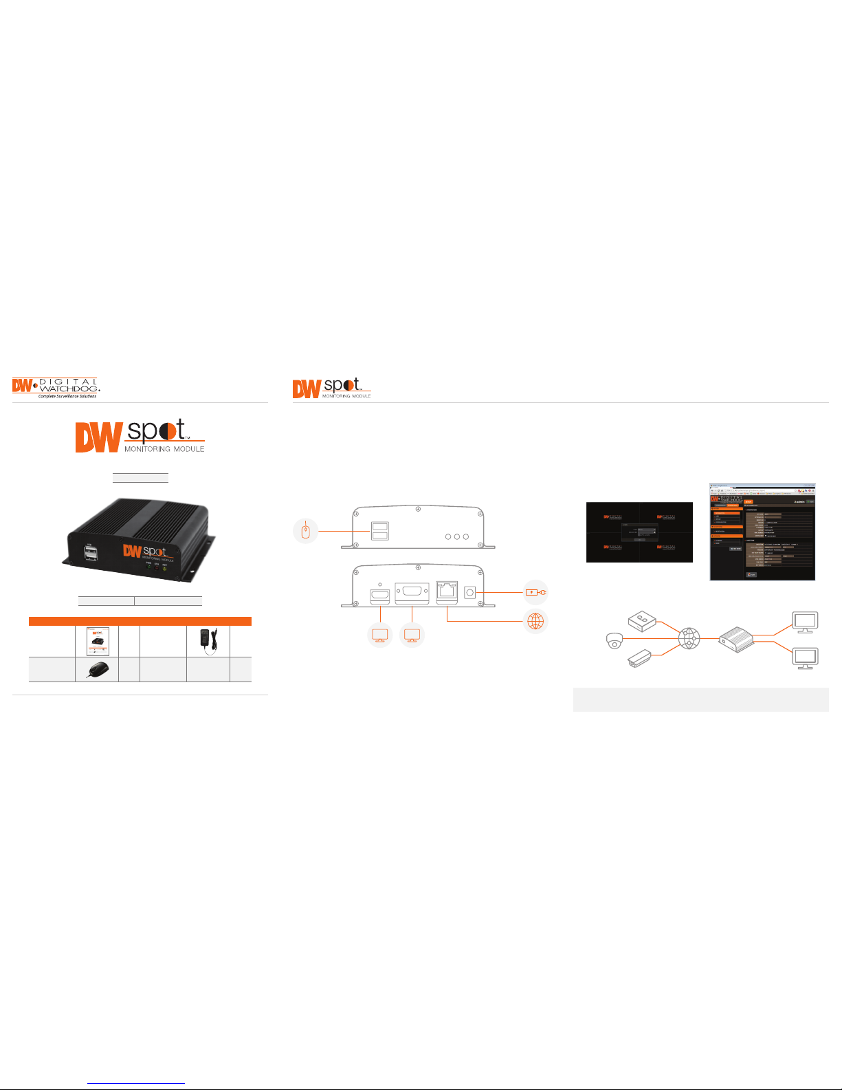
WHAT’S IN THE B OX
QSG Manual 1 Set 12V DC Power Cable 1 Set
USB Mouse 1 Set
Quick Start Guide
Username: admin Password: no password
Tel: 866-44 6-3595 / 813-8 88-9555
Technical Support Hou rs: 9:00AM – 8:0 0PM EST, Monday thru Friday
digital-watchdog.com
Quick Start Guide
Step 1 – SETTING UP THE SPOT MONITORING MODULE OFF SITE
Step 2 – POWERING UP THE SPOT MONITORING MODULE
SAFET Y TIPS
1. Connect the modu le to an appropriate power supply.
2. Connect the module to a local monitor off site for conguration.
3. Make sure the module is connected to the sa me network as your IP Cameras, VM AX AHD Core
™
DVRs
or VMAX IP Plus™ NVR.
1. When the module bo ots up, it will be in protective mode. This means you w ill not be able to access the
module’s setup menu until you e nter the proper username and pas sword.
2. To unlock the module, right-clic k anywhere on the screen. The lo gin screen will appear. (Default
Username / Password: adm in / no password)
3. When the module boots up for the rst time, you w ill be guided through the Star tup Wizard.
4. You can also access the S pot monitor for basic setup via its web browse r.
1. During the boot up p rocess, the module should not be inter rupted by pressing any buttons on th e mouse.
Do not unplug the power a dapter or turn the module off dur ing the boot up process.
2. A UPS (Uninterrupted Power Supply) is highl y recommended to prevent damage to the mo dule during a
power outage.
The Digital Watchdog Spot™ Monitoring Modu le requires only 2 steps to complete the instal lation—local
conguration off-site, and power and monitor connection at the site.
DW-HDSPOTMOD
ONVIF
IP Cameras
VMAX AHD CORE
™
DVRs
and VMAX IP Plus
™
NVRs
Network
DW Spot
VGA Output
VGA
HDMI Output
HD
FRONT PANEL
BACK PANEL
PWR STA
USB
DC 12V
LANVGA OUTHD OUT
NET
POWER SUPPLY
NETWORK PORT
USB MOUSE
VGAHD
NOTE: The Digital Watch dog Spot Monitoring Module supp orts up to 16 supported devices registe red,
with quad (4-channel) vi ew only.
Page 2
Step 4 – CONNECT THE MONITOR ON SITE
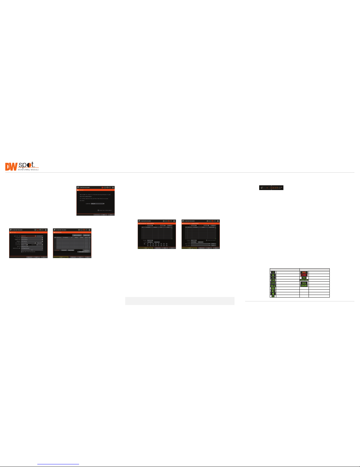
4. Search and register all suppor ted devices with the module. You can search for ON VIF conformant IP
Cameras, VMAX A HD Core™ DVRs and VMAX I P Plus™ NVRs.
5. The module’s Registration screen allows y ou to detect all the cameras in your netwo rk and automatically
add them to the NVR. Sele ct one of the following options:
a. DVR/NV R Search – To search for VMAX AHD Core
™
DVRs and VMAX I P Plus™ NVRs:
• Press the ‘SEARC H (DVR/NVR)’ Button. The system will sca n the network automatically. You can
also press the SEA RCH button to scan the networ k again.
• Select the DVR/NV R you wish to register from the search resul ts and press the ‘GET INFO’ but ton
to obtain the device’s streamin g prole. DETAIL INFO allows you to get more informat ion on the
device’s individual stre ams.
• If necessar y, enter the user ID and pas sword for the device you are registering.
• You can also select which chan nels from the DVR/NVR you wish to reg ister.
• Click ‘APPLY’ to register your device.
b. Camera Search – To search for a ny ONVIF conformant IP camera:
• Press the ‘SEARC H (CAM)’ Button. The system will scan the net work automatically. You can also
press the SEARC H button to scan the network aga in.
• Select the camera you w ish to register from the search results an d press the ‘GET INFO’ button
to obtain the device’s streamin g prole. DETAIL INFO allows you to get more informat ion on the
device’s individual stre ams and setup each of the camera’s streams re motely.
• You can select multiple came ras by checking the ‘CAMERA MULTI SELE CT’ button. Cameras
selected will be highli ghted in orange.
• If necessary, select the which stream from the camera to view (depend on camera’s capabilities).
• If needed, enter the user I D and password for the device you are regi stering.
• Click ‘APPLY’ to register your device. Cameras will b e registered in the order in which they a ppear.
Cameras that are alrea dy registered will be shown in gray.
Once all the setup for th e module is completed off site:
1. Install the module in its permanent location.
2. Connect the module to a proper power supp ly.
3. Connect the module to an HD or VGA monitor.
4. Power up the module, and make sure the displ ay setup is correct.
Quick Start Guide
Rev Date: 10/15 © 2015 Digital Watch dog. All right s reser ved.
Step 5 – SYSTEM OPERATIONS
Menu Bar
You can view the Spot Monitorin g Module’s menu bar by moving the cursor of a US B mouse over the
bottom of the module’s screen. T he following options will appear:
• Open the System Menu.
• View a selected chann el in full screen mode.
• Switch to 4-channel view m ode.
• Start/Stop sequence.
• Select a specic cha nnel from the 16 registered channels.
• Power down the Spot Moni toring Module.
• Pin the menu bar to keep it in v iew.
Pop-Up Menu
When right-clickin g on the module’s display, the following options will app ear:
• DISPLAY MODE: Select the di splay option.
• CHANGE NEX T CH: Show the next channel.
• SEQUENCE: Start/Stop sequence view.
• FREEZE: Freeze the cur rent view.
• SYSTEM STATUS: Show the system status in real time.
• MENU: Open the setup men u screen.
Display Icons
For DVRs and NVRs, the Sp ot Monitoring Module can show ea ch channel’s current status based on t he
settings in the DVR or N VR. When supported, some of the fol lowing icons may appear on the ch annel’s
display.
Step 3 – STARTUP WIZARD
1. Follow the start up wizard’s instructions to setup the mo dule’s
basic settings, incl uding language, network and d evice
search and registrat ion. At any time you can skip steps, go
back, or exit the wiza rd and setup the module manually.
2. Language – Select the appropriate la nguage from the drop-
down menu options. Pres s Apply to Save and Next to move
to the next step.
3. Set the module’s network settings to match you r network’s
requirements. It is recom mended to set the network ty pe to
DHCP and let the modu le auto-detect the network’s settin gs,
then change the t ype to Static. Please contact your Net work
Administrator for additi onal information. Press Apply to Save
and Next to move to the next s tep.
NOTE: Screen shots are for refer ence only. Actual GUI may differ.
Icon on Each Channel Screen Icon on Main Screen
Continuous Recording No HDD or HDD Failure
Motion Recording Emergency Recording
Sensor Recording PTZ Mode
Continuous & Motion Recording Warning for Overheated Temp
Continuous & Sensor Recording Sequence Mode
Motion & Sensor Recording Digital Zoom Mode
Sensor Activated
Motion Activated
Audio Channel
PTZ Camera
 Loading...