

Page 1

Please read this manual thoroughly before use and keep it handy for future reference.
Rev: 0219
USER MANUAL
Rev: 03/19
Page 2

CAUTION
User manual | 2
CAUTION
RISK OF ELECTRIC SHOCK DO NOT
OPEN
WARNING: TO REDUCE THE RISK OF ELECTRIC SHOCK, DO NOT REMOVE COVER
(OR BACK).
NO USER-SERVICABLE PARTS INSIDE.
REFER SERVICING TO QUALIFIED SERVICE PERSONNEL
WARNING
TO REDUCE THE RISK OF FIRE OR ELECTRIC SHOCK, DO NOT EX- POSE THIS PRODUCT TO RAIN OR
MOISTURE. DO NOT INSERT ANY METALLIC OBJECT THROUGH THE VENTILATION GRILLS OR OTHE R
OPENNINGS ON THE EQUIPMENT.
EXPLANATION OF GRAPHICAL SYMBOLS
The lightning flash with arrowhead symbol, within an equilateral triangle, is in- tended to alert
the user to the presence of dangerous voltage within the products
cient magnitude to constitute a risk of electric shock
to persons.
enclosure that may be of suffi-
The exclamation point within an equilateral triangle is intended to alert the user to the presence of important operating and maintenance (servicing) instructions
in the literature accompa-
nying the product.
Page 3

FCC COMPLIANCE STATEMENT
This device complies with Part 15 of the FCC Rules. Operation is subject to the following two conditions:
(1) this device may not cause harmful interference, and (2) this device must accept any interference received,
including interference that may cause undesired operation.
FCC INFORMATION:
for a “Class A” digital device, pursuant to Part 15 of the FCC Rules. These limits are designed to provide
reasonable protection against harmful interference when the equipment is operated
environment. This equipment generates, uses, and can radiate radio frequency energy and, if not installed
and used in accordance with the instruction manual, may cause harmful interference to radio
communications. Operation of this equip
which case the user will be required to correct the interference at his own expense.
CAUTION:
complian
This Class A digital apparatus complies with Canadian ICES-003.
Cet
Canada.
WARNING
This is a Class A product. In a domestic environment this product
case
CAUTION
RISK OF EXPLOSION IF
ACCORDING
This equipment has been tested and found to comply with the limits
ment in a residential area is likely to cause harmful interference in
in a commercial
Changes or modifications not expressly approved by the party responsible for
ce could void the user’s authority to operate the equipment.
appareil nume` rique de la classe A est conforme a´ la norme NMB-003 du
may cause radio interference in which
the user may be required to take adequate measures.
CE COMPLIANCE STATEMENT
BATTERY IS REPLACED BY AN INCORRECT TYPE. DISPOSE OF USED BATTERIES
TO THE INSTRUCTIONS.
Page 4

User manual | 4
IMPORTANT SAFETY INSTRUCTIONS
1. Read these instructions.
2. Keep these instructions.
3. Heed all warnings.
4. Follow all instructions.
5. Do not use this apparatus near water.
6. Clean only with dry cloth.
7. Do not block any ventilation openings. Install in accordance with the manufacturer’s instructions.
8. Do not install near any heat sources such as radiators, heat registers, stoves, or other apparatus (in-
cluding amplifiers) that produce heat.
9. Do not defeat the safety purpose of the polarized or grounding-type plug. A polarized plug has two
blades with one wider than the other. A grounding type plug has two blades and a third grounding
prong. The wide blade or the third prong is provided for your safety. If the provided plug does not fit
into your outlet, consult an electrician for replacement of the obsolete outlet.
10. Protect the power cord from being walked on or pinched particularly at plugs, convenience recepta-
cles, and the point where they exit from the apparatus.
11. Only use attachments/accessories specified by the manufacturer.
12. Use only with the cart, stand, tripod, bracket, or table specified by the manu-
facturer, or sold with the apparatus. When a cart is used, use caution when
moving the cart/apparatus combination to avoid injury from tip-over.
13. Unplug this apparatus during lightning storms or when unused for long peri-
ods of time.
14. Refer all servicing to qualified service personnel. Servicing is required when
the apparatus has been damaged in any way, such as power-supply cord or
plug is damaged, liquid has been spilled or objects have fallen into the apparatus, the apparatus has been exposed to rain or moisture, does not operate
normally, or has been dropped.
15. CAUTION – THESE SERVICING INSTRUCTIONS ARE FOR USE BY QUALIFIED SERVICE PERSONNEL
ONLY. TO REDUCE THE RISK OF ELECTRIC SHOCK DO NOT PERFORM ANY SERVICING OTHER
THAN THAT CONTAINED IN THE OPERATING INSTRUCTIONS UNLESS YOU ARE QUALIFIED TO DO
SO.
16. Use satisfy clause 2.5 of IEC60950-1/UL60950-1 or Certified/Listed Class 2 power source only.
17. ITE is to be connected only to PoE networks without routing to the outside plant.
Page 5

5 | Compressor™ Onvif Encoder
Table of Contents
Table of Contents ............................................................................................................................... 5
1. Overview 7
1.1 Package contents ....................................................................................................................... 8
1.2 Encoder description .................................................................................................................... 8
2. Installation 9
2.1 Connecting exterior devices ......................................................................................................... 9
2.2 Starting the system .................................................................................................................. 11
2.3 Quick Setup ............................................................................................................................. 11
2.3.1 Account ...................................................................................................................... 11
2.3.2 System ....................................................................................................................... 12
2.3.3 Network ..................................................................................................................... 12
2.3.4 Time/Date .................................................................................................................. 12
3. Live Screen Configuration 13
3.1 Icons in live screen ................................................................................................................... 14
3.2 Live launcher menu .................................................................................................................. 15
3.3 Quick menu ............................................................................................................................. 16
3.3.1 PTZ control ................................................................................................................. 17
3.3.2 Status > System log .................................................................................................... 18
3.3.3 Status > Event ............................................................................................................ 19
3.3.4 Status > Stream .......................................................................................................... 20
4. Setup menu 21
4.1 General buttons in setup menu .................................................................................................. 22
4.2 SYSTEM ................................................................................................................................... 23
4.2.1 System ....................................................................................................................... 23
4.2.2 Time/Date .................................................................................................................. 25
4.2.3 Account > User ........................................................................................................... 28
4.2.4 Configuration (Config) ................................................................................................. 30
4.3 CAMERA .................................................................................................................................. 32
4.3.1 Basic .......................................................................................................................... 32
4.3.2 Advanced ................................................................................................................... 34
4.4 DEVICE ................................................................................................................................... 36
4.4.1 Display ....................................................................................................................... 36
4.4.2 PTZ > PTZ .................................................................................................................. 41
4.4.3 Serial Device > Serial Device ........................................................................................ 42
Page 6

User manual | 6
4.5 EVENT ..................................................................................................................................... 43
4.5.1 System ....................................................................................................................... 43
4.5.2 Alarm In ..................................................................................................................... 44
4.5.3 Motion ........................................................................................................................ 47
4.5.4 Video Loss > Setup ..................................................................................................... 49
4.5.5 Notification ................................................................................................................. 50
4.6 NETWORK ............................................................................................................................... 52
4.6.1 Basic > WAN Port ........................................................................................................ 52
4.6.2 DVRNS/DDNS ............................................................................................................. 53
4.6.3 E-Mail......................................................................................................................... 55
4.6.4 Notification Server ....................................................................................................... 56
5. Webviewer Error! Bookmark not defined.
5.1 How to monitor with web v ie wer ................................................................................................ 58
5.1.1 In case of selecting Viewer (Internet Explorer) ............................................................... 59
5.1.2 In case of selecting Setup ............................................................................................ 60
6. Products Specifications 61
Page 7

7 | Compressor™ Onvif Encoder
1. Overview
This chapter describes the encoder, its components and their terms and features.
This manual introduces a 16ch HD Encoder which monitors and controls HD analog cameras.
Users can monitor HD analog cameras through network and also can be monitored by local HDMI monitor.
The device features include the following:
The most cost-effective path to IP
•
Supports HD-Analog, HD-TVI and all CVBS signals up to 2.1MP/1080p resolution
•
Connect your analog cameras to DW Spectrum® IPVMS or any ONVIF approved CMS
•
Convert up to 16 analog cameras to an IP video signals
•
Real-time 480fps 2.1MP/1080p, 720p and 960H resolution at local monitoring output
•
Simultaneous streaming
•
Works with DW Spectrum® IPVMS recording license (needs 4 x DW-SPCP04LSC004, sold sep-
•
arately)
Support motion detection
•
Support two-way audio (4 input, 1 output)
•
1x RS-485 Interface for PTZ control
•
Search and playback from DW Spectrum® IPVMS
•
Frame rate and bandwidth control
•
4 alarm input, 1 alarm output
•
Event notifications via e-mail with image
•
ONVIF conformant, Profile S
•
Page 8
1.1 Package contents
Note
No
Name
No
Name
No.
Name
Function
1
3
4
2
The device package contents consist of the following:
Please check all components involved.
Table 1-1 Package contents
1 Encoder 3 Quick guide
2 DC Power Adapter & Power cord
1.2 Encoder description
Refer to the diagrams below for buttons description and ports on the back of the encoder.
User manual | 8
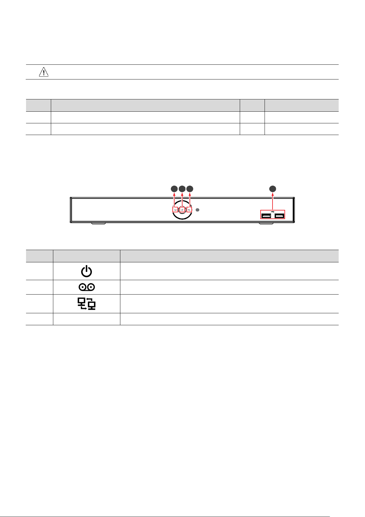
Figure 1-1 Name and Connection of each front section
Table 1-2 Name and Function of each front section
1
2
3
4 USB port The encoder includes 2 USB ports
Power is on/off.
Not in use.
The encoder is being accessed remotely via the network.
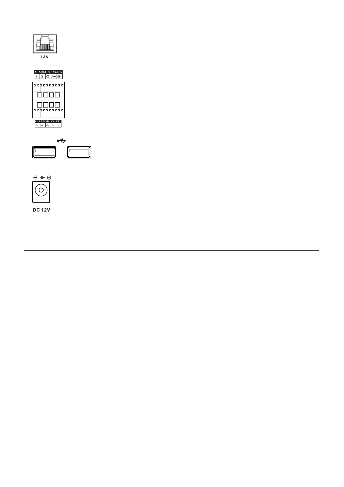
Figure 1-2 Name and Connection of each rear section
Page 9

9 | Compressor™ Onvif Encoder
Figure 2-1 Connection map
2. Installation
Mount and install any external devices such as cameras, sensors and microphones according to the installation
instructions. Connect the external devices to the encoder’s rear based on the diagram above. Below is an example
of a proper connection between the Compressor, the cameras, and your remote monitoring software.
2.1 Connecting exterior devices
How to connect external devices to the ports in the back of the device:
1
Place the unit in a stable flat surface.
2
Do NOT install the device too close to the wall. Protrusive connectors in the rear of the unit may be forcedly
curved or pressed, which can cause fires, electric shocks, or injury.
3
When connecting external devices to the encoder, make sure the system is off and the power cable is disconnected.
4
Connect analog cameras to the video in ports in the back of the encoder. The encoder will detect the camera’s
signal automatically upon connection.
5
Connect a microphone to the audio input ports and a speaker to the audio output port. Be sure to check
regulations in the area whether recording to be legal or not.
6
Connect a monitor to the VGA, HDMI or CVBS port.
Page 10
User manual | 10
Note
7
Connect a network cable to the network port.
8
Connect an alarm and RS485 devices to the terminal block as needed.
9
Connect a USB mouse to either one of the USB ports in front panel of the unit.
10
Once all external devices are connected properly, connect the encoder to an adequate power supply using the
included cables.
The encoder does not have a power button. The system boots up automatically upon
connection to an external power source.
Page 11

11 | Compressor™ Onvif Encoder
Note
Attention
2.3.1
Account
a new user name
password
OK, then Save
Next
2.2 Starting the system
Once all external devices have been connected to the back of the encoder, and the encoder has been added to
the network properly, per the example above, power up the encoder and begin the quick setup wizard.
1
When the encoder boots up, it will be in protective mode. You will not be able to access the encoder’s setup
menu until you login using the proper username and password.
2
To unlock the encoder, right-click anywhere on the screen. The login screen will appear. (Default user name /
password: admin / admin)
3
When the encoder boots up for the first time, you will be guided through the Startup Wizard. It is highly
recommended that you change your password after initial setup for security purposes.
Default user name and password are admin/admin.
Click to see the encoder’s MAC address.
If you lost your password, contact DW’s technical support to reset it.
Please change password after login due to security.
2.3 Quick Setup
The quick setup wizard helps users setup the encoder’s main settings, including account setup, system settings,
network settings and date and time settings.
1
Click the keyboard icon to set
default admin password.
2
Press
3
Press
button to end Account setting.
to save the changes.
and
. It is highly recommended to change the
Page 12

2.3.2 System
1
Adjust the system settings in this screen:
Language: Select system language.
Device Name: Enter the device name.
Keyboard ID: Setup the encoder’s ID to match the ID settings of a key-
board controller. If you are controlling multiple encoders, setup different
IDs for each encoder.
HDMI / VGA: Set the resolution for the local monitor output
connection.
2
Press Save button to save changes.
3
Press Next to end system settings.
2.3.3 Network
Set the encoder’s network settings to match your network’s
1.
requirements. It is recommended to set the network type to DHCP
and let the encoder auto-detect the network’s settings. Then,
change the type to Static.
Please contact your network administrator for more information.
User manual | 12
WAN Port: Select whether to use static IP or dynamic IP.
IP Address, Subnet Mask, Gateway, DNS, and Port: If dynamic
network has been selected in the WAN Port options, all these
settings will be adjusted automatically to match your network.
If Static IP is selected, manually enter all the necessary information.
2.
Press Save button to save changes.
3.
Press Next
to end Network settings.
2.3.4 Time/Date
1. Set each item in Time/Date setting screen.
Network Time Sync: Select network for synchronizing with a time server.
System Time: Select if you do not wish to synchronize your en-
coder with a network time server. Set the device time and select
whether to enable Daylight saving time (DST).
Time Zone: Select time zone for the system being installed.
DST Start/End: For Daylight saving time, set the application
start and end dates.
2. Press Save button to save changes.
3. Press Next to end Time/Date setting.
Page 13

13 | Compressor™ Onvif Encoder
Figure 3-1 UI Screen Configuration
Table 3-1 Items and Description of UI Screen Configuration
No.
Item
Description
3. Live Screen Configuration
Below image is the encoder’s main UI.
1 Setup menu Located on the top of the screen. See “4 Setup” for more information.
2 Live screen Shows live video for the connected cameras.
3 Launcher menu Located on the bottom of the screen. See “3.2 Live Launcher” for more information.
4 Quick menu Right-click anywhere on the screen to open the quick menu options. See “3.3 Quick” for
more information.
Page 14
User manual | 14
Note
No.
Icon
Description
3.1 Icons in live screen
When viewing live video from the cameras connected to the encoder, a series of icons will display on the screen.
Each representing a different setting or notification related to the selected channel.
Chosen live screen is marked with a blue frame. Mouse-located live screen is marked as yellow one.
Figure 3-2 Live screen icon
Table 3-2 Live screen icon and its description
1 CH1 CAM1 Channel numbers and camera titles.
2 A camera with PTZ function.
3 PTZ control function in process.
4 Video loss.
5 Mic on/off.
6
7
Speaker on/off.
Displaying current time and date.
Page 15
15 | Compressor™ Onvif Encoder
Figure 3-3 Launcher menu
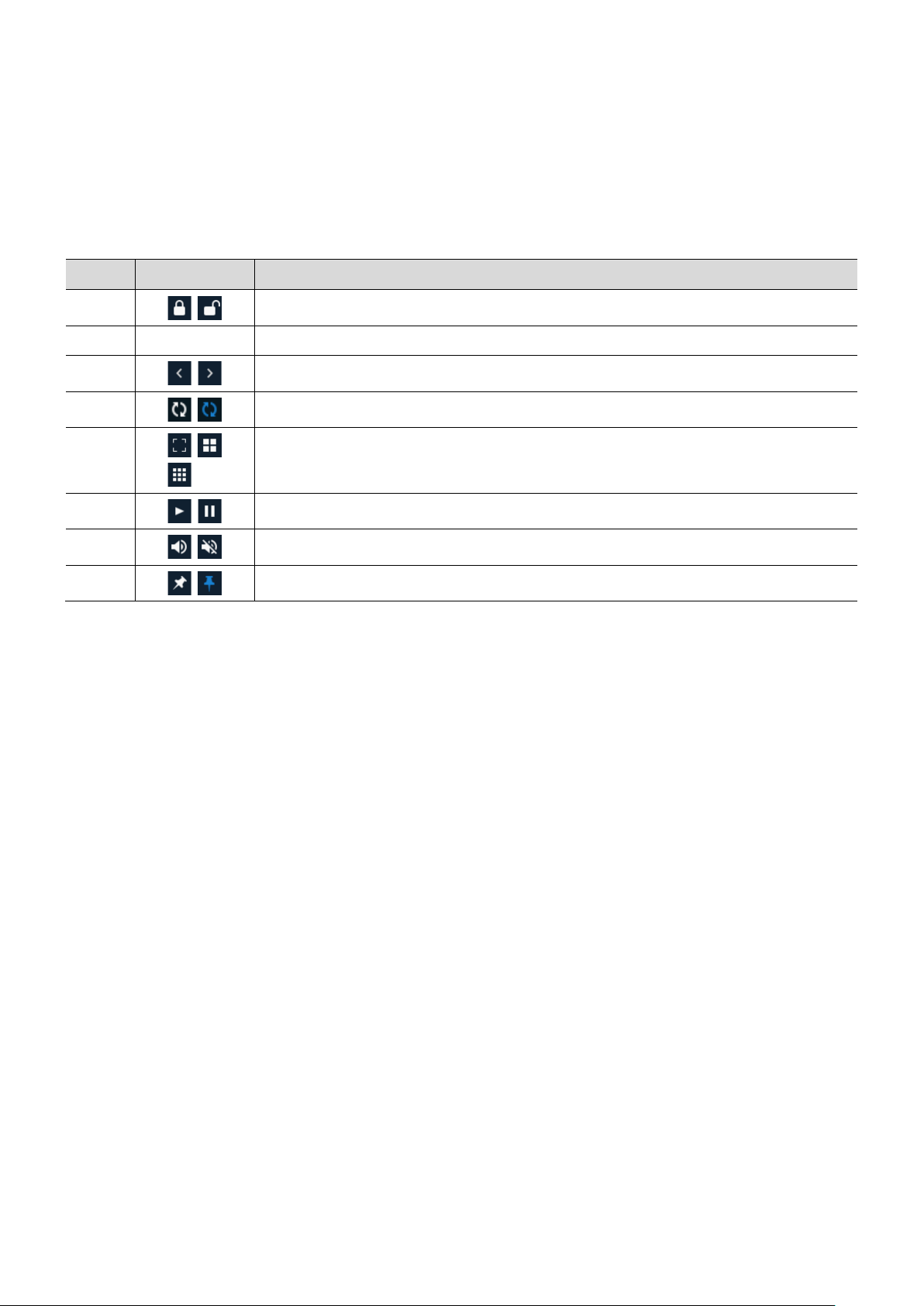
Table 3-3 Launcher menu Item and Description
No.
Item
Description
3.2 Live launcher menu
The launch menu is the main menu bar located at the bottom of the encoder’s screen.
1
2 Date and time Displaying current date and time.
3
4
5
6
7
8
Log in/out status and logged in ID.
Move to previous/next split view screen or next single screen view.
Display channels in sequence (toggle)
Select the screen split mode in live screen (single screen, 4-, 9-, and 16-
split view options).
Stop or play selected live screen images (toggle).
Audio on or mute for selected live screen (toggle).
Pin the launcher menu to always show or hide (toggle).
Page 16

User manual | 16
No.
Item
Description
3.3 Quick menu
The quick menu is available by right-clicking anywhere on the encoder’s screen. The available options are:
Figure 3-4 Quick menu
Table 3-4 Quick menu Item and Description
1 Screen mode Select the split view mode of live screen (single screen, 4-, 9-, and 16-
split view options).
2 Zoom in Digital zoom into a selected live screen (zoom out, 2x, 4x and 8x).
3 Freeze Freeze the video selected (toggle).
4 Speaker output/ mute Turn on or off audio.
5 PTZ control Enable or disable PTZ function.
6 Stop alarm Stop monitoring alarm output and event.
7 Spot monitor Set the output mode of a spot monitor (Auto, full and 4x4).
8 Setup Open the settings menu. See section “4. Setup” for more information.
9 Status Show the device’s system log, event and stream status.
10 Log in/log out Log out of the current user or log into a new user.
11 Shutdown Shuts down the device.
Page 17
17 | Compressor™ Onvif Encoder
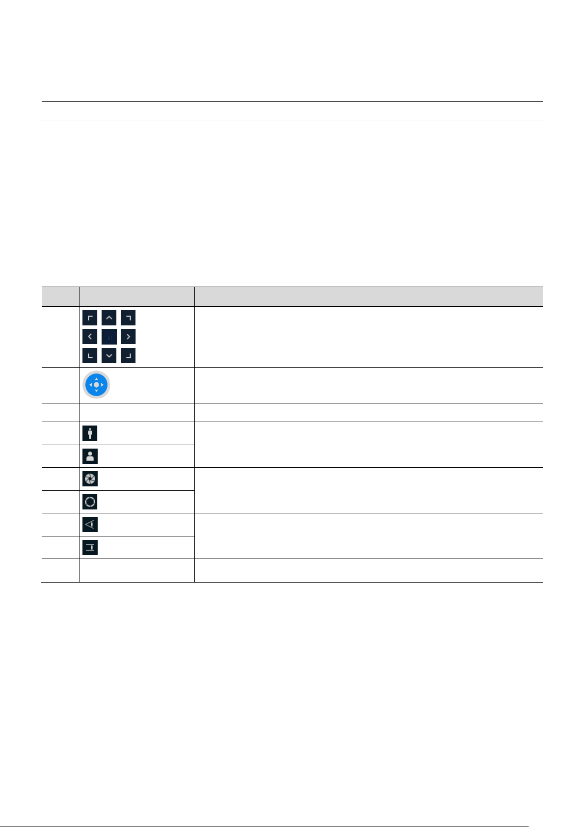
3.3.1
PTZ control
Note
DEVICE > PTZ
Figure 3-5 Quick menu > PTZ control
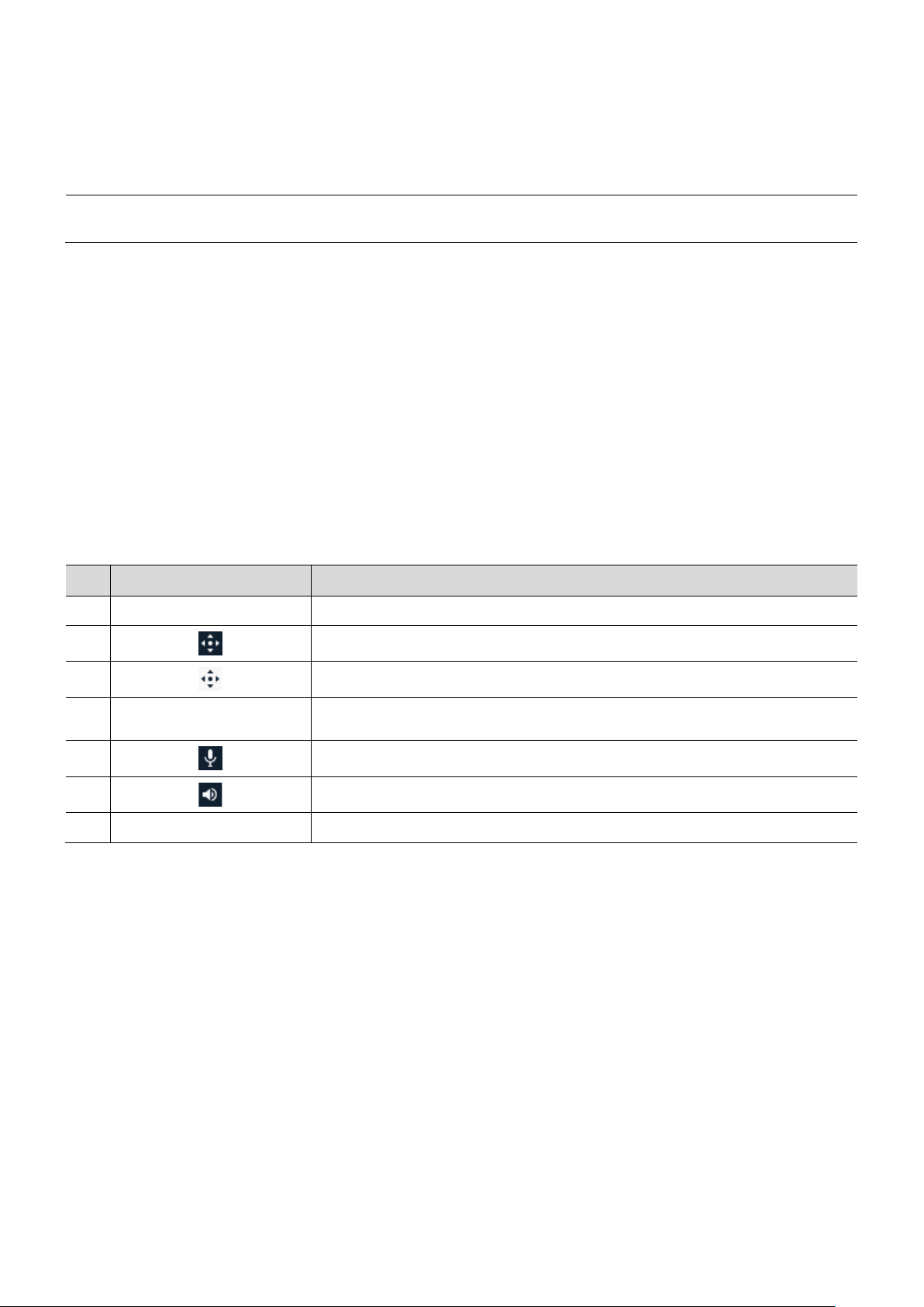
Table 3-5 Quick menu > PTZ control item and description
No.
Item
Description
For PTZ cameras connected to the encoder, use the PTZ control to move the camera and adjust settings as
needed.
2
To enable PTZ Control menu, go to
1
Move the camera’s view with direction buttons.
Move the camera’s view with PTZ ball.
in the upper live screen.
3 AF Adjust screen focus automatically.
4 Zoom out
Zoom function on supported PTZ camera.
5
6
7 IRIS on
8 Focus far
9
10 Open the camera’s menu.
Zoom in
IRIS off
Adjust iris in the camera on supported models.
Manual focus adjustment on supported models.
Focus near
Page 18

In PTZ Control screen, right-click anywhereon the screen to open the PTZ quick menu options.
No.
Item
Description
No.
Item
Description
Figure 3-6 PTZ control Quick menu
Table 3-6 PTZ control’s quick menu Item and description
Preset, Tour, Scan,
1
Pattern
Run PTZ functions on supported models.
User manual | 18
2 Exit
Exit the PTZ quick menu and open the live view quick menu (PTZ mode still
enabled)
3.3.2 Status > System log
Users can see the system log information in System log tap in Status screen.
Figure 3-7 Status > System log
Table 3-7 Status of Quick menu > System log items and description
1 Start Setting starting time of system log to search.
2 End Setting ending time of system log to search.
3 Log type Selecting log types (Network, Setup, and System).
4 Select all /unselect
all
5 Search Pressing search button search on the basis of set condition.
6 System log list Displaying system log lists.
7 Cancel Completing the status screen.
Selecting or clearing all log types (toggle).
Page 19

19 | Compressor™ Onvif Encoder
3.3.3 Status > Event
Figure 3-8 Status > Event
Table 3-8 Status > Event Item and Description in Quick menu
No.
Item
Description
When selecting Status from the quick menu options, users can see real-time event information for the unit.
1
2 Refresh Delete event list.
3 Event list Display event list.
4 Cancel Complete status screen.
Show or hide an event list (toggle).
Page 20

User manual | 20
No.
Item
Description
3.3.4 Status > Stream
When selecting Status from the quick menu options, users can see the streaming information for the unit.
Figure 3-9 Status > Stream
Table 3-9 Status > Stream items and description
1 Input type Display input video type.
2 Main stream Display main stream status.
3 Second stream Display second stream status.
Page 21

21 | Compressor™ Onvif Encoder
Figure 4-1 Setup menu
Table 4-1 Setup menu tree
Category
Sub-category
Section
4. Setup menu
Setup is available from the quick menu by right-clicking anywhere and selecting Setup.
SYSTEM
CAMERA
DEVICE
System
System
F/W Upgrade
Time/Date
Time/Date
Holiday
Account User
Export/Import
Configuration
Factory Default
Basic
Basic
Audio In/Out
Scan Mode
Advanced
Advanced
Display
Spot
Display
OSD
Sequence
PTZ PTZ
EVENT
NETWORK
Serial Device Serial Device
System System
Setup
Alarm In
Schedule
Setup
Motion
Schedule
Video Loss Setup
Periodic
Notification
Schedule
Basic WAN Port
DVRNS/Dashboard
DVRNS/DDNS
DDNS
E-Mail E-Mail
Notification Server
Notification Server
Notification Message
Page 22

4.1 General buttons in setup menu
No.
Item
Description
Figure 4-2 General buttons in setup menu
User manual | 22
Table 4-1 Item and Description of General buttons in setup menu
1 Default Restore settings to their factory default.
2 Save Save changes to the encoder’s settings.
3 Cancel Cancel changes to the encoder’s settings.
4 Restore Cancel changes to the encoder’s settings and restore to the last saved values.
5 Apply Apply changes to the encoder’s settings.
Page 23

23 | Compressor™ Onvif Encoder
4.2.1
System
Figure 4-3 SYSTEM > System > System
Table 4-2 SYSTEM > System > System Item and Description
No.
Name
Function
4.2 SYSTEM
Setup the system’s basic settings and update the firmware.
1 Language Set the system’s language.
2 Device name Enter the device’s name (English characters only).
3 Video type Select image standard types (NTSC or PAL) .
4 Keyboard ID Select keyboard ID (1~255).
5 System start If enabled the encoder will run the setup wizard every time it reboots.
6 Run Run the setup wizard.
Page 24

4.2.1.1 System > F/W Upgrade
No.
Name
Function
Upgrade the system’s firmware.
User manual | 24
Figure 4-4 SYSTEM > System > F/W Upgrade
Table 4-3 SYSTEM > System > F/W Upgrade Item and Description
1 Current version Display the firmware version currently installed.
2 Device Connect a USB memory with new firmware files to upgrade the system’s
firmware.
Page 25

25 | Compressor™ Onvif Encoder
4.2.2 Time/Date
4.2.2.1 Time/Date > Time/Date
Table 4-4 SYSTEM > Time/Date > Time/Date Item and Description
No.
Name
Function
Set the date, time, and holidays of the system.
Set the date, time, and holidays of the system.
Figure 4-5 SYSTEM > Time/Date > Time/Date
1 System time
2 DST start Set the starting date of DST
3 DST end Set the ending date of DST
4 Display format Select the format to display date and time.
5 Time zone Select time zone.
6 Network time sync When using a specific network time server, click the “Use” checkbox and enter
7 NTP server Select whether to use an NTP server.
Set the date and time.
DST: select whether to use daylight saving time
Time change: save changed time.
the server address.
Sync. Interval: select synchronization period (1~7-hour)
Last Sync. Time: displaying the final synchronized time
Page 26

4.2.2.2 Time/Date > Holiday
No.
Name
Function
Set specific days as holidays. These can later have their own settings, alarms and notifications.
Figure 4-6 SYSTEM > Time/Date > Holiday
User manual | 26
Table 4-5 SYSTEM > Time/Date > Holiday Item and Description
1 Yea r Select the year to set a holidays.
2
3 Add holiday Add a holiday.
4 List Show the holiday list.
Delete selected holiday.
Page 27

27 | Compressor™ Onvif Encoder
Add Holiday” button is selected, the following window will appear. Use the options to select the
date, the type of holiday and when how will it repeat itself each year.
Figure 4-7 SYSTEM > Time/Date > Holiday > Add Holiday
Table 4-6 SYSTEM > Time/Date > Holiday > Add Holiday Item and Description
No.
Name
Function
Relative
1, first, 1 will
When the “
2 Date Display chosen date.
3 Ty p e Select the holiday type.
1 Name Enter the holiday’s name.
Fixed will set the specific numeric day of the month as a holiday (e.g., 4th of July).
will set the day of the week and its position in the month as a holiday
(e.g.,
designate the first Sunday of January as a holiday).
4 Calendar Select the holiday to add.
Page 28

4.2.3 Account > User
No.
Name
Function
Add or modify user accounts and their access rights to the system.
Figure 4-8 SYSTEM > Account > User
User manual | 28
Table 4-7 SYSTEM > Account > User Item and Description
1 Add group Add a new users’ group.
2 Add user Add a new user.
3 Group list Display all groups.
4 User list Display all users across all groups.
5 Live view
restricted access
6 Auto login Click/clear automatic login checkbox.
7 Auto logout Select automatic logout time (Null, 1 min, 2 min, 3 min, 4 min, 5 min, 6 min, 7 min,
8 Password change
cycle
Do not display live video if the system is not logged into a user.
8 min, 9 min, 10 min, and 30 min).
If enable, user will be required to change their password periodically.
Page 29

29 | Compressor™ Onvif Encoder
Add Group”. The
Figure 4-9 SYSTEM > Account > User > Add Group
Table 4-8 SYSTEM > Account > User > Add Group Item and Description
No.
Name
Function
Add User”. The setup window below will appear.
Figure 4-10 SYSTEM > Account > User > Add User
Table 4-9 SYSTEM > Account > User > Add User Item and Description
No.
Name
Function
To add a new user group, press “
levels for this group on this page. You can allow all users assigned to the group access to live view, PTZ control,
access to the setup menu, or firmware update rights. You can also assign specific channels or limit what channels
users in the group can view. You must have at least one group setup to add users (see below).
1 Name Enter the group’s name.
2 Permission Select the access level for this group.
3
Select what channels to permit users in the group access to.
screen below will appear. You can setup the specific permission
To add a user, press “
password and assign to a group.
1 Name Enter the user name.
2 ID Enter the user ID. This will be the ID used to log into the system.
Enter the new user’s name, user ID and
3 Password Enter the password.
4 Confirm password Confirm the password.
5 Group Select to the group to which belongs.
Page 30

User manual | 30
No.
Name
Function
4.2.4 Configuration (Config.)
In this menu, you can import and export settings or reset the system to its factory default settings.
4.2.4.1 Config. > Export/Import
You can export the current system’s settings to a USB or import settings from a different system.
Figure 4-11 SYSTEM > Config. > Export/Import
Table 4-10 SYSTEM > Config. > Export/Import Item and Description
1 Device Select an exterior connector with USB.
USB: displays the USB device connected.
Refresh button: re-scan for external devices.
2 Import Apply information saved in USB to the device.
Import system settings from a different system.
If import Config with network setup, the network settings information is
brought from the setting information.
Import button: The file in USB is brought to the designated device.
3 Export Save the set information in the USB.
Export system settings and save them to a USB.
If Export Config with network setup, the network settings information is saved
with the system settings onto the USB.
Export button: Save the set information in the USB.
Page 31

31 | Compressor™ Onvif Encoder
4.2.4.2 Config > Factory Default
Figure 4-12 SYSTEM > Config > Factory Default
Table 4-11 SYSTEM > Config > Factory Default Item and Description
No.
Name
Function
Restore the system to its factory settings. Check the boxes next to the settings you wish to reset or click “Select
All”. Click “Default” to confirm the reset.
1 Select all /
unselect all
2 Default item Select related items to be defaulted.
3 Default button Default the system to the basics.
Select all items to be defaulted.
Page 32

User manual | 32
No.
Name
Function
4.3 CAMERA
In the CAMERA menu, you can adjust the settings for the cameras connected with the device.
4.3.1 Basic
Set the basic functions of camera and audio.
4.3.1.1 Basic > Basic
Set the basic items for each channel. You can edit the channel’s title and set a channel as a covert channel.
Figure 4-13 CAMERA > Basic > Basic
Table 4-12 CAMERA > Basic > Basic Item and Description
1 CH Display the channel’s name.
2 Title Enter the channel’s name to identify the cameras.
3 Covert Set a channel to covert channel. Select if images from this channel will be visible
in the Live screen, or show only the channel’s status (OFF, Video Only,
Video/State All).
4 Copy covert
Setup
Apply the covert settings from one channel to multiple channels.
Page 33

33 | Compressor™ Onvif Encoder
Copy Covert Setup
Figure 4-14 CAMERA > Basic > Basic > Copy Covert Setup
Table 4-13 CAMERA > Basic > Basic > Copy Covert Setup Item and Description
No.
Name
Function
4.3.1.2 Basic > Audio In/Out
Figure 4-15 CAMERA >Basic > Audio In
Table 4-14 CAMERA > Basic > Audio In Item and Description
No.
Name
Function
Press
Check the boxes next to each channel you want to apply the same settings.
1 From Select a channel converted setting.
2 To Select a channel to be copied.
button. The screen below will appear. Select which channel to copy the settings from.
3 Select all /
unselect all
Setup audio input and output for supported decives.
Select all channels.
1 No Display channels of audio.
2 Use Select to enable audio.
3 Assign Select channels to be assigned audio.
Page 34

User manual | 34
No.
Name
Function
4.3.2 Advanced
Set camera video, stream and privacy mask settings for each channel.
4.3.2.1 Advanced > Scan Mode
Use this screen to adjust the signal detected from the camera as needed. The system supported HD-Analog and
HD-TVI. You can also setup the signal detection to auto, allowing the system to detect the signal automatically.
Figure 4-16 CAMERA > Advanced > Scan Mode
Table 4-15 CAMERA > Advanced > Scan Mode Item and Description
1 CH Display channels.
2 Scan mode Automatically detects the camera’s signal type (Auto, HD-Analog, and HD-TVI).
3 Copy scan
mode
4.3.2.2 Advanced > Advanced
Setup each channels’ brightness, contrast and color and set privacy masks in the cameras’ field of view (FoV).
Copy the current settings to other channels.
Figure 4-17 CAMERA > Advanced > Advanced
Page 35

35 | Compressor™ Onvif Encoder
Table 4-16 CAMERA > Advanced > Advanced Item and Description
No.
Name
Function
Figure 4-18 CAMERA > Advanced > Privacy Mask
Table 4-17 CAMERA > Advanced > Privacy Mask Item and Description
No.
Name
Function
4.3.2.3 How to set Privacy Mask
New Mask. Mask Zone
Mask1
Mask Zone
Mask Zone
Delete Mask
Apply
1 CH Display channels.
2 Video Set brightness, contrast, and color of the camera.
3 Privacy mask Set the privacy field; display field numbers set in parenthesis (setup up to 4
masks per channel).
Click the Editing Icon ( ) in the right corner, then Privacy Mask screen will be shown.
1 CH Select channels to set privacy field.
2 Privacy mask Select whether to use privacy field.
3 New mask Select privacy field again.
4 Delete mask Delete selected privacy field.
Users can set 4 privacy masks:
1. Press
2. Drag the area you want in the screen with a mouse.
3. Press
• Revision: Select Mask No. in
• Deletion: Select Mask No. in
button to complete setting.
is automatically set as
and drag the area you want in the screen with a mouse.
and click
.
.
Page 36

User manual | 36
No.
Name
Function
4.4 DEVICE
In the DEVICE menu, set the device’s display, PTZ settings and other external devices connected to the unit.
4.4.1 Display
Set the system’s live screen display settings.
4.4.1.1 Display > Display
Set the display settings. You can adjust the resolution of the local output monitor, enable pop-up event screens
and enable a monitor relay switch.
Figure 4-19 DEVICE > Display > Display
Table 4-18 DEVICE > Display > Display Item and Description
1 HDMI/VGA Select the resolution of the display device
(available: 1024x768. 1280x720, 1920x1080).
2 Event popup Set duration of event popup. When enabled, a popup screen will appear
when an alarm is triggered, showing the relevant channel.
3 Monitor relay switch Send an alarm out when the screen’s layout changes.
Page 37

37 | Compressor™ Onvif Encoder
4.4.1.2 Display > Spot
Figure 4-20 DEVICE > Display > Spot
Table 4-19 DEVICE > Display > Spot Item and Description
No.
Name
Function
Set the Spot output settings.
1 Sequence Set the channel and dwell time (5, 10, 20, 30sec) when Auto mode is selected.
2 Event popup Sets the hold time for full screen images of a channel when an event occurs
(available options: off, 5, 10, 20, 30sec, continuous).
If multiple channels have an event at the same time, the event channel is shown
as a spilt screen.
Page 38

4.4.1.3 Display > OSD
No.
Name
Function
Set the on screen display (OSD) settings.
Figure 4-21 DEVICE > Display > OSD
User manual | 38
Table 4-20 DEVICE > Display > OSD Item and Description
1 Camera name Select the way to display camera in live screen (Off, CH+Title, CH).
2 Live bar Select the way to display the live bar (always on, auto hide).
3 Display icon Select what icons to display in the live screen.
Page 39

39 | Compressor™ Onvif Encoder
4.4.1.4 Display > Sequence
Figure 4-22 DEVICE > Display > Sequence
Table 4-21 DEVICE > Display > Sequence Item and Description
No.
Name
Function
Setup a sequence view for the live display.
1 Quad sequence Set a sequence showing 4 channels at a time.
2 Division Select the screen partition mode (Full or quad).
3 Sequence list Display the sequence list based on division selected.
4 Add sequence Add items to the play sequence.
5 NO. Shows the channels in their display order.
6 Division Displays as full, 2X2 (quad).
7 CH list Set the channels order in the sequence.
8 Dwell time Set the dwell time for each channel (3 sec~30 sec)
9 Default Change all settings back to default settings.
10
11
Revise the list.
Delete the list.
Page 40

User manual | 40
No.
Name
Function
Click on Add Sequence to add a new sequence. The screen below will appear. Select the channel, set the dwell
time and the division type of the sequence (full screen or quad mode).
Figure 4-23 DEVICE > Display > Sequence > Add Sequence
Table 4-22 DEVICE > Display > Sequence > Add Sequence Item and Description
1 Dwell time Select dwell time to show each channel (3 sec, 5 sec, 10 sec, 15 sec, and 30 sec).
2 Division Select the partition screen to play (full, quad).
3 Channel selection Select which channels to include in the sequence.
Page 41

41 | Compressor™ Onvif Encoder
4.4.2 PTZ > PTZ
Figure 4-24 DEVICE > PTZ > PTZ
Table 4-23 DEVICE > PTZ > PTZ Item and Description
No.
Name
Function
Note
To use PTZ menu to setup PTZ enabled cameras.
1 Copy PTZ Setup Apply setting from a selected channel to multiple channels.
2 CH Channels number.
3 ID Select the camera’s ID (set from 1 to 255).
4 Protocol Select protocol of the camera connected to the selected channel.
5 Speed Select pan-tilt speed of camera connected to the selected channel. Set from 1 to
5 with 1 being the slowest and 5 the fastest.
For more information about camera ID, protocol information, and details, see the PTZ
camera’s user manual.
Page 42

4.4.3 Serial Device > Serial Device
No.
Name
Function
Setup a serial device connected to the system such as PTZ cameras and USB devices.
Figure 4-25 DEVICE > Serial Device > Serial Device
User manual | 42
Table 4-24 DEVICE > Serial Device > Serial Device Item and Description
1 USB (to serial) Set communication transmission value of USB device.
2 RS-485 Set communication transmission value of RS-485 connector.
Page 43

43 | Compressor™ Onvif Encoder
the EVENT menu
4.5.1
System
4.5.1.1 System > System
Figure 4-26 Event > System > System
Table 4-25 Event > System > System Item and Description
No.
Name
Function
4.5 EVENT
In
Set the system events that would trigger alarms.
Set the system event of the device
, users can setup notifications, alarm and sensors, video loss and motion detection.
1 System restart Enable system reboot as an event.
2 Notification Select to send an e-mail or push mobile notifications when an event occurs.
3 User login Enable user-login as an event.
Page 44

4.5.2 Alarm In
No.
Name
Function
Set sensor alarms and schedule
4.5.2.1 Alarm In > Setup
Set sensor alarms
User manual | 44
Figure 4-27 Event > Alarm In > Setup
Table 4-26 Event > Alarm In > Setup Item and Description
1 Sensor Sensor’s channel number.
2 Use Enable a sensor.
3 Ty p e Select sensor types (N.O, N.C).
4 Beep Set a beep sound when a sensor is activated. Select from the available length op-
tions (null, 5 sec, 10 sec, 20 sec, 30 sec, 1 min, 10 min, 30 min, and 1 hour).
5 Alarm Set an alarm option when a sensor is activated.
6 Noti. Select to send an e-mail notification when a sensor is activated.
7 Preset Set a PTZ camera to move to a specific preset when a sensor is activated.
8 Copy alarm setup Apply setting from a selected channel to multiple channels.
Page 45

45 | Compressor™ Onvif Encoder
Alarm, Group Rec, Noti., Preset
Figure 4-28 Event > Alarm In > Setup > Event: Alarm
Table 4-27 Event > Alarm In > Setup > Event: Alarm Item and Description
No.
Name
Function
Click on the editing Icon ( ) next to
to show the following screen:
1 Alarm-out Set the alarm.
Relay: enable a relay output when an event occurs.
•
Dwell time: set a duration for an alarm (Keep, 5 sec, 10 sec, 20 sec, 30 sec, 1
•
min, 10 min, 30 min, and 1 hour)
2 Monitor popup Enable a monitor popup when an event occurs.
3
3 Remote notification Setup an e-mail or push notifications to your smart phone when an event occurs.
4 Preset Preset of PTZ camera is running.
Select which channel to popup on the monitor when an event occurs.
Use: enable a PTZ camera’s preset as an action when an event occurs.
•
CH: select channels. Please note a PTZ camera must be connected to the
•
channel.
Preset: enter the preset value.
•
Page 46

User manual | 46
No.
Name
Function
drag the mouse across the areas in the table you want to setup. To complete the
4.5.2.2 Alarm In > Schedule
Setup a schedule when sensors are active. You can setup individual schedules for each sensor connected to the
encoder, or copy and apply the same schedule to all devices.
Figure 4-29 Event > Alarm In > Schedule
Table 4-28 Event > Alarm In > Schedule Item and Description
1 Sensor Select the sensor to set the schedule for.
2 Schedule type Select the types of schedules. If None is selected, the sensor will be disabled.
3 Schedule table Displays the operating schedule for the selected sensor. 7 days of the week and
holidays are shown on the left, and 24 hours of each day are shown on the top
row. Each square represents an hour in a specific day. If the square is orange,
the sensor is activated during that time and day.
4 Drag field You can select multiple hours and days for quick setup. To do so, click and hold
on any square in the schedule table. While holding the mouse’ left button down,
setup, release the mouse’s button. .
5 Copy to alarm
schedule button
Apply setting from a selected channel to multiple channels.
Page 47

47 | Compressor™ Onvif Encoder
4.5.3 Motion
4.5.3.1 Motion > Setup
Figure 4-30 Event > Motion > Setup
Table 4-29 Event > Motion > Setup Item and Description
No.
Name
Function
Note
Alarm, Noti., Preset
Event: Motion
Set and schedule motion detection for each of the system’s channels.
Set motion detection
1 CH Show channel’s number.
2 Use Enable motion detection for each channel.
3 Area Display the motion detection area.
4 Sens. Select the sensitivity level for motion detection (Level 1~10).
5 Beep Set a beep sound when motion is detected. Select from the available length
options (null, 5 sec, 10 sec, 20 sec, 30 sec, 1 min, 10 min, 30 min, and 1 hour).
6 Alarm Set an alarm output when motion is detected.
7 Noti. Set an e-mail notification when motion is detected.
8 Preset Set a PTZ camera to move to a specific preset when motion is detected.
9 Copy to motion
setup
Placing your mouse on
displays Event: Alarm screen. For more information about
“
4.5.2 Alarm In > Setup in Alarm In.”
Apply setting from a selected channel to multiple channels.
and clicking editing icon ( ) in right corner
screen, see section
Page 48

4.5.3.2 Motion > Schedule
No.
Name
Function
e you want to setup. To complete the
To schedule record time when the motion sensor detects across channels
User manual | 48
Figure 4-31 Event > Motion > Schedule
Table 4-30 Event > Motion > Schedule Item and Description
1 CH Select the channel to set the motion detection schedule for.
2 Schedule type Select the types of schedules. If None is selected, the motion detection will be
disabled.
3 Schedule table Displays the operating schedule for the selected channel. 7 days of the week
and holidays are shown on the left, and 24 hours of each day are shown on the
top row. Each square represents an hour in a specific day. If the square is blue,
motion detection is activated during that time and day.
4 Drag field You can select multiple hours and days for quick setup. To do so, click and hold
on any square in the schedule table. While holding the mouse’ left button down,
drag the mouse across the areas in the tabl
setup, release the mouse’s button. .
5 Copy to motion
schedule button
Apply setting from a selected channel to multiple channels.
Page 49

49 | Compressor™ Onvif Encoder
4.5.4 Video Loss > Setup
Figure 4-32 Event > Video Loss > Setup
Table 4-31 Event > Video Loss > Setup Item and Description
No.
Name
Function
Note
Alarm, Noti., Preset
Event: Video Loss
Event: Video Loss
To set Video Loss across channels
1 CH Show channel’s number.
2 Use Enable video loss event for each channel.
3 Beep Set a beep sound when video loss is detected. Select from the available length
options (null, 5 sec, 10 sec, 20 sec, 30 sec, 1 min, 10 min, 30 min, and 1 hour).
4 Alarm Set an alarm output when video loss is detected.
5 Noti. Set an e-mail notification when video loss is detected.
6 Preset Set a PTZ camera to move to a specific preset when video loss is detected.
7 Copy to Video Loss
Setup
Placing your mouse on
displays
see section “
Copy the Video Loss set value to other channels.
and clicking editing icon ( ) in right corner
screen. For more information about
4.5.2 Alarm In > Setup in Alarm In.”
screen,
Page 50

User manual | 50
No.
Name
Function
4.5.5 Notification
Set and schedule notifications for alarms and events.
4.5.5.1 Notification > Periodic
Set a periodic alarm. This alarm will go out to an e-mail every set amount of time with information about a selected channel’s events.
Figure 4-33 EVENT > Notification > Periodic
Table 4-32 EVENT > Notification > Periodic Item and Description
1 Periodic
notification
2 Summary Send event information.
3 Interval Select how often the e-mail will be sent (5 min, 10 min, 30 min, and 1 hour, 2-hour,
4 Select CH Select channels to be included in the e-mail.
5 Select All /
Unselect All
Enable periodic alarms.
6-hour, 8-hour, 12-hour, and 24-hour).
Select/deselect all channels
Page 51

51 | Compressor™ Onvif Encoder
4.5.5.2 Notification > Schedule
Figure 4-34 EVENT > Notification > Schedule
Table 4-33 EVENT > Notification > Schedule Item and Description
No.
Name
Function
Schedule remote notification (alarm and motion)
1 Schedule type Select the types of schedules. If None is selected, notifications will be disa-
bled. Select green to enable e-mail notifications, blue for push mobile
notification or purple to enable both.
2 Schedule table Displays the operating schedule for enabled notifications. 7 days of the week
and holidays are shown on the left, and 24 hours of each day are shown on
the top row. Each square represents an hour in a specific day.
3 Drag field You can select multiple hours and days for quick setup. To do so, click and
hold on any square in the schedule table. While holding the mouse’ left button
down, drag the mouse across the areas in the table you want to setup. To
complete the setup, release the mouse’s button. .
Page 52

User manual | 52
No.
Name
Function
4.6 NETWORK
In the NETWORK menu, users may set the network environment. Please contact your network administrator for
more information.
4.6.1 Basic > WAN Port
Set the system’s network environment
Figure 4-35 NETWORK > Basic > WAN Port
Table 4-34 NETWORK > Basic > WAN Port Item and Description
1 Static IP Check to use a static IP. If this option is selected, manually enter the device’s
IP address, subnet mask and gateway information.
2 DHCP (Dynamic) Check to use DHCP (Dynamic). If selected, the system will scan the network and
automatically assign itself the proper IP address, subnet mask and gateway according to the network settings.
3 MAC address View the device’s MAC Address.
4 DNS Select manual and enter a DNS address or choose auto to set automatically.
5 Port (TCP) Enter the TCP port information.
6 Port (web) Enter the web port information.
7 Bandwidth limit Set a limit to the amount of bandwidth the device can use in the network (no lim-
its, 50Mbps, 10Mbps, 5Mbps, 2Mbps, 1Mbps, 500Kbps, 400Kbps, 300Kbps,
200Kbps, and 100Kbps).
8 Ping test Enter an IP address in the ping test to complete the test.
Page 53

53 | Compressor™ Onvif Encoder
4.6.2 DVRNS/DDNS
4.6.2.1 DVRNS/DDNS > DVRNS/Dashboard
Figure 4-36 NETWORK > DVRNS/DDNS > DVRNS/Dashboard
Table 4-35 NETWORK > DVRNS/DDNS > DVRNS/Dashboard Item and Description
No.
Name
Function
Set DVRNS/DDNS
Register a DVRNS/Dashboard account
1 DVRNS Register a DVRNS account
ID: enter DVRNS ID (default: MAC address of the unit).
•
Password: enter DVRNS password.
•
Register: register DVRNS account.
•
2 Dashboard Add/delete a dashboard account
Account: select the type of account (existing account or new account).
•
ID: enter your dashboard ID.
•
Password: Enter your dashboard password.
•
Add Device: add a dashboard account.
•
Delete Device: delete a dashboard account.
•
Page 54

4.6.2.2 DVRNS/DDNS > DDNS
No.
Name
Function
Set a DDNS site for remote users to access
Figure 4-37 NETWORK > DVRNS/DDNS > DDNS
User manual | 54
Table 4-36 NETWORK > DVRNS/DDNS > DDNS Item and Description
1 DDNS site Select DDNS site from the available options.
2 Host name Enter the host name.
3 User name Enter the user name.
4 User password Enter the user password.
Page 55

55 | Compressor™ Onvif Encoder
4.6.3 E-Mail
Figure 4-38 NETWORK > E-Mail > E-Mail
Table 4-37 NETWORK > E-Mail > E-Mail Item and Description
No.
Name
Function
Set an e-mail server to send e-mail notifications when events occur.
1 Server type Select an SMTP server.
gmail.com
•
hotmail.com
•
aol.com
•
nave r.com
•
daum.com
•
2 Address / port Enter the server address and port number.
3 Image attach Set to add a JPEG image to the e-mails.
4 Authentication Select/deselect using authentication and password.
5 ID Enter the email ID.
6 Password Enter the email password.
7 Sender Enter a sender’s name.
8 Receiver Enter the receiver’s information. To add multiple e-mail addresses as receivers,
separate each address with a comma.
9 Tes t Verify whether the email server is set normally.
Page 56

4.6.4 Notification Server
No.
Name
Function
TCP can check the results in the recorder, but UDP should be checked in the
4.6.4.1 Notification Server > Notification Server
Setup a notification server. When an event occurs, a notification will be sent to a server.
User manual | 56
Figure 4-39 NETWORK > Notification Server > Notification Server
Table 4-38 NETWORK > Notification Server > Notification Server Item and Description
1 Notification server Select/deselect whether to use notification server.
2 Type Select TCP or UDP protocol.
3 IP Enter the server’s IP address or host name.
4 Port Enter the server’s port.
Send a test message to the server to check the connection status. Click
5 Tes t
Save when the transmission is successful.
notification server.
Page 57

57 | Compressor™ Onvif Encoder
4.6.4.2 Notification Server > Notification Message
Figure 4-40 NETWORK > Notification Server > Notification Message
Table 4-39 NETWORK > Notification Server > Notification Message Item and Description
No.
Name
Function
Add
Add Message
Figure 4-41 NETWORK > Notification Server > Notification Message > Add Message
Table 4-40 NETWORK > Notification Server > Notification Message > Add Message
Set up a message to be sent to the notification server when event occurs.
1
2 Add Notification message edit window pop-up.
3 CH Camera channel.
4 Event Display event type as Motion, Alarm, and Video Loss.
5 Message Display notification message.
Click the
button to open the
Deleted registered notification message.
screen below:
No. Name Function
1 CH Select the channel to add a message.
2 Event Select the event type (motion, alarm, video loss).
3 Message Create a message to send.
Page 58

User manual | 58
Item
Recommended
Minimum
5. Web viewer
This chapter describes web viewer for monitoring video form the device through a PC in remote mode.
5.1 How to monitor with web viewer
Table 5-1 System Requirement for Web viewer
OS Microsoft® Windows® 10 x86 (64bit) (Home
Premium, Professional, Ultimate)
Microsoft® Windows® 8 (pro, Enterprise)
CPU Intel Core™ i5-2550 3.30GHz or higher
RAM 2GB or higher 1.5GB or higher
VGA ATI Radeon™ HD 3650 or NVIDIA GeForce
8400GS or higher(1280x1024, 32bpp or
Higher), Multi Monitor
HDD Over 6GB Over 1GB
LAN Gigabit Ethernet 10/100 Mbps Ethernet
Enter IP address of the encoder in your
1
Internet browser. Please note that you
may have to open ports in your router
in order to access the encoder from a
separate network. Please contact your
network administrator for more
information.
Microsoft® Windows® XP Home SP3
Intel Core™ 2 Duo E7200 2.53GHz or higher
ATI Radeon™ HD 2400 or NVIDIA GeForce
FX5500 or higher(1024x768, 24bpp or higher)
Enter ID and password, and click one of
2
the buttons:
Viewer: view live images.
•
Setup: enter the encoder’s setup
•
menu remotely.
To view live video from the encoder, you will be prompted to download and install Java. Follow the next page’s
instructions to properly download and install the Java files.
Page 59

59 | Compressor™ Onvif Encoder
5.1.1
In case of selecting Viewer (Internet Explorer)
Viewer
Viewer
Keep
Click
1
When Java download screen opens,
2
download and install JAVA.
Live images may be monitored.
3
.
In case of selecting Viewer (Chrome)
1
After click
downloaded.
Click
button.
, .jnlp file can be
Page 60

User manual | 60
webviewer_chrome.jnlp
Click
2
When Java download screen opens,
3
download and install JAVA.
Live images may be monitored.
4
.
5.1.2 In case of selecting Setup
Users can set the menu in similar ways with local connected monitor.
Figure 5-1 Setup screen
Page 61

61 | Compressor™ Onvif Encoder
6. Products Specifications
VIDEO
Video input
Video out
Display mode
Compression H.264
Resolution
PERFORMANCE
Interface
Signal type HD-Analog, HD-TVI and analog signal up to 960H
CH# 16CH BNC input
Outputs and
Resolutions
Audio in and out 4 RCA input / 1 RCA output
Alarm in and out 4 alarm inputs / 1 output, terminal block
RS-485 / UTC
Motion detection Locally and via DW Spectrum® IPVMS
True HD / VGA: 1920x1080, 1280x720, 1024x768
Spot: 1.0 Vp-p (75 ohm, Composite)
True HD/VGA: 1/4/9/16 Split, PIP, Sequence
Spot: 1/16 Split, Sequence
Main stream: 240fps @ 2.1MP/ 1080p
Sub Stream: 240fps @ VGA
1 terminal block
PTZ control via UTC (HD-Analog / HD-TVI / HD-CVI)
Privacy masks Yes
Locally and via DW Spectrum® IPVMS.
Features
NETWORK
Network connection 1 RJ45 10/100/1000 Base-T
Streaming
Access
Alarm management
Notifications E-mail notifications
Security HTTPS, SSL, Multi User Authority
Transmission speed
live
Max. throughput 288Mbps
Bandwidth Support bandwidth control
Protocols ONVIF, TCP/IP, UDP, DHCP, uPNP, DDNS, Zeroconf, Bonjour
Web viewer Internet Explorer® XP or higher with live view and remote setup
software DW Spectrum® IPVMS
Motion detection, sensor and alarm activation, video loss, system start and
user login
Max. 240fps @ 1080p
Page 62

GENERAL
User manual | 62
Operating temperature and
humidity
Other certifications FCC
Power requirement 12V DC, 2A
Electrical
Power consumption Max. 14.4W, 1.2A
Dimensions 14.76" x 1.76" x 12.52" (375 x 44.9 x 318.2 mm)
Wei ght 3.96lbs (1.8kg)
※ Specifications are subject to change without notice.
32°F ~ 113°F (0°C ~ 45°C)
Less than 90% (non-condensing)
 Loading...