

Page 1
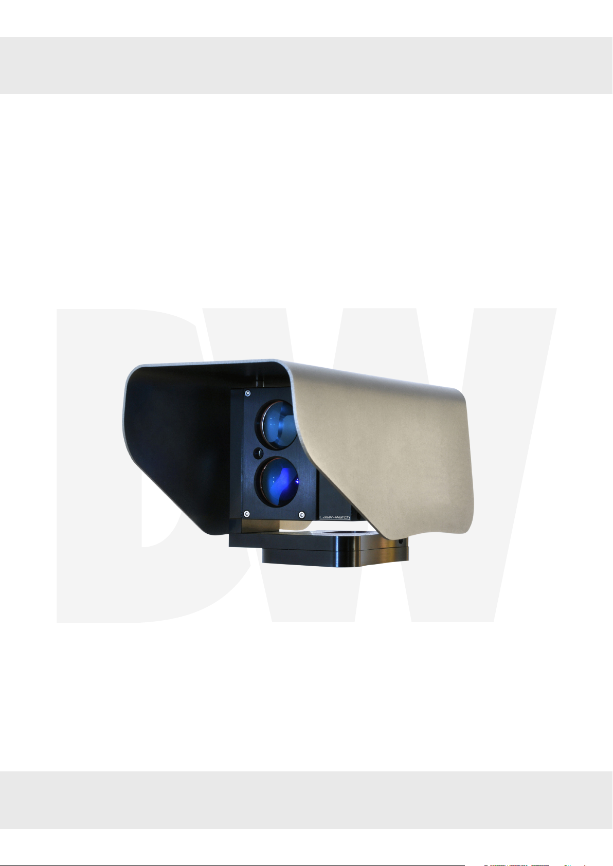
SiteWatch™ laser sensor
DW-DTLA500
User’s Manual Ver. 09/19
Before installing and using the camera, please read this manual carefully.
Be sure to keep it handy for future reference.
Page 2
Safety Information
BEFORE OPERATION
This section of the manual uses the following warning symbols to provide information regarding use of
the product to prevent you and others from being harmed and your product from being damaged. These
warning symbols are described below. Ensure you understand these precautions before proceeding with the
installation.
Warning
Caution
Never attempt to disassemble or repair the product. It may cause fire or damage to the devices.
Hold the main unit securely when you install or service it. Exercise care not to bump the product against
nearby objects or drop it inadvertently.
Failure to follow the instructions provided by this
warning and improper handling may cause death
or serious injury
Failure to follow the instructions provided by this
caution and improper handling may cause injury
and/or property damage
Warning
This symbol indicates
prohibition. The specific
prohibited action is provided in
and/or around the figure.
This symbol requires an action or gives an instruction.
Caution
Only use approved Power over Ethernet power supplies.
Never try to power the device other than with the
RJ45 PoE connection.
Do not touch the unit connections with a wet hand or when
the product is wet from rain. It may cause a short circuit and
damage the unit.
Clean and check the products periodically for safe use.
If any problem is found, contact DW® or authorized
partners to solve the issue before continuing to use the
product.
This product is intended to detect people and is not
designed to prevent theft, disasters or accidents.
The manufacturer shall not be held liable for any
damage to user’s property resulting from theft,
disasters or accidents.
Page 3

Contents
INTRODUCTION
04 Specifications
05 Before operation
05 Part identification
05 Preparing to mount the laser sensor
06 Cabling the laser sensor
INSTALLATION AND DETECTION METHODS
06 Detection methods
06 Perimeter detection
06 Spot surveillance
06 Change detection
OPERATION PRINCIPLES
07 Sensor placement
07 Laser divergence
07 Multiple reflections
08 Alarm zones
09 Combining SiteWatch™ laser sensor with cameras
ALARM SETTINGS
15 Alarm settings
15 Zone alarms
16 Alarm zones actions
17 Reference point
18 Timer/Heartbeat
19 Weather alarm
19 Logout
20 WARRANTY
21 LIMITS AND EXCLUSIONS
INSTALLATION AND ANGLE ADJUSTMENT
10 Alignment
10 Hardware reset
USER INTERFACE
11 Factory default settings
11 Login
11 Installation and configuration
11 Alignment
12 Device configuration
13 Import and export settings
14 Firmware update
Page 4

Introduction
The DW-DTLA500 is a laser surveillance sensor that allows the user to monitor and locate intrusions for applications
where physical fences are not desirable, possible or where enhanced security is required. The 1640ft (500m) sensor
works without reflectors and reacts in fractions of a second. The DW-DTLA500 SiteWatch™ sensor knows the exact
position of an object and oers adaptive alarm settings. For example, the sensor can be set to react to cars only in a
specific lane and alarm if an object has stopped or if a door opens, while ignoring all other activities.
1.1. SPECIFICATIONS
FIELD OF APPLICATION Outdoor surveillance and monitoring
ALARM ZONES
ALARM ACTIONS
SELF AWARENESS
DETECTION RANGE 0 - 1640ft (500m)
DETECTION RESOLUTION +/- 1 dm
UPDAT E R AT E 250 Hz
LASER WAVELENGTH 905nm
BEAM DIVERGENCE 2.0 x 2.0 mRad
ALIGNMENT LASER Yes
LASER CLASS Class 2 laser product, eye-safe
POWER SUPPLY Power over Ethernet (48V DC) or 12 V DC
POWER CONSUMPTION 4W (PoE class 2)
OPERATING TEMPERATURE -22°F to +140°F (-30°C to +60°C)
INTERFACE
RELAY SWITC H Max 30V 200mA, NC and NO
MOUNTING
ENCLOSURE RATING IP66
COLOR Shell: gray, sensor: black
WEIGHT 2.4Kg
Warranty 1 year warranty
Up to 20 fully adaptable zones, each zone
has individual alarm sensitivity settings
and alarm actions.
Network alarm, relay. Easy direct integration with
IP to VMS, enabling PTZ control, automatic video
recording and object position.
Adaptive digital processing algorithm
suppresses noise from fog and snow,
and detects challenging weather to allow
alarms to VMS.
Ethernet IEEE 802. 3af, TCP/IP,
web browser user interface
4 x M5 - Bosch compatible
2.87 ” x 1.61” (73 x 41mm)
4 x M5 - Axis compatible
1.57” x 2.44” (40 x 62mm)
2 x M6 - common standard
2.87 ” (73mm C-C)
5/8”-11 UNC (tripod mount)
1.2. BEFORE OPERATION
The SiteWatch™ laser sensor is designed to be intuitive and easy to use. To ensure best performance, all users should
read this instruction manual carefully before use.
4
Page 5
Precautions
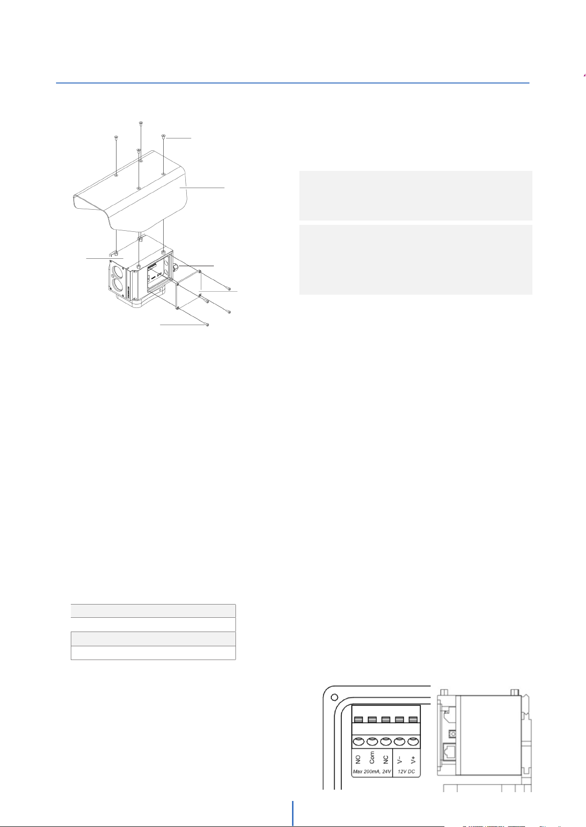
1.3. PART IDENTIFICATION
Shell screw
(Countersunk M4x6 mm)
NOTE: The sensor must always be mounted on
a steady foundation, such as a wall or a
pole that is well secured to minimize risk of
misalignment due to vibrations.
NOTE: The sensor has a maximum detection range
of up to 1640.42ft (500m). Recommended
range for demanding applications is
984.25ft (300m) to ensure detection of
small objects such as people, even in dicult
weather conditions.
Main unit
Service lid screw (M3x8 mm)
Shell
Cable gland
Service lid
1.4. PREPARING TO MOUNT THE LASER SENSOR
1. Do not stare directly into the red alignment laser. Do not leave the red alignment laser turned on after installation process
is complete.
2. Use wall brackets and tripod with compatible mounting only.
3. Install the product on a solid surface.
4. Install the product so that the detection line is not obscured by interference from tall grass or tree branches waving in
the wind.
5. For perimeter protection, the unit should be placed at an optional detection height and parallel to ground.
6. Do not install or leave the product in a location exposed to heat, vibration or impact.
7. The SiteWatch™ laser sensor is compatible with a number of conventional wall brackets used for surveillance cameras, all
standard accessories, such as pole mounts, corner mounts etc., can be used.
8. When using the product for mobile applications, the threaded UNC 5/8” - 11 hole is compatible with most surveyor
tripods.
9. Using the mounting accessory, mark and drill all necessary holes in the mounting surface.
1.5. CABLING THE LASER SENSOR
The SiteWatch™ laser sensor is powered with Po E and all communication is made with TCP/IP. For applications that require cables
over 328ft (100m) between unit location and nearest switch or router it is necessary to use network extenders or fiber optics.
1. Remove the shell and service lid.
2. Insert the network cable without a connector through the cable gland. Crimp RJ45 connector to the cable then plug into
the RJ45 jack.
Power input
Power over Ethernet (48V DC) or 12V DC
Power consumption
4W, class 2
3. Tighten the cable gland to secure the cable and seal the casing.
4. If the relay is desired to be used, replace the plug on the
backside with supplied cable gland.
5. Connect the signal cable to the terminals. Choose
connection for desired function, normally open (N/O)
or normally closed (N/C).
6. Replace the service lid and shell.
5
Page 6
Installation
2. INSTALLATION AND DETECTION METHODS
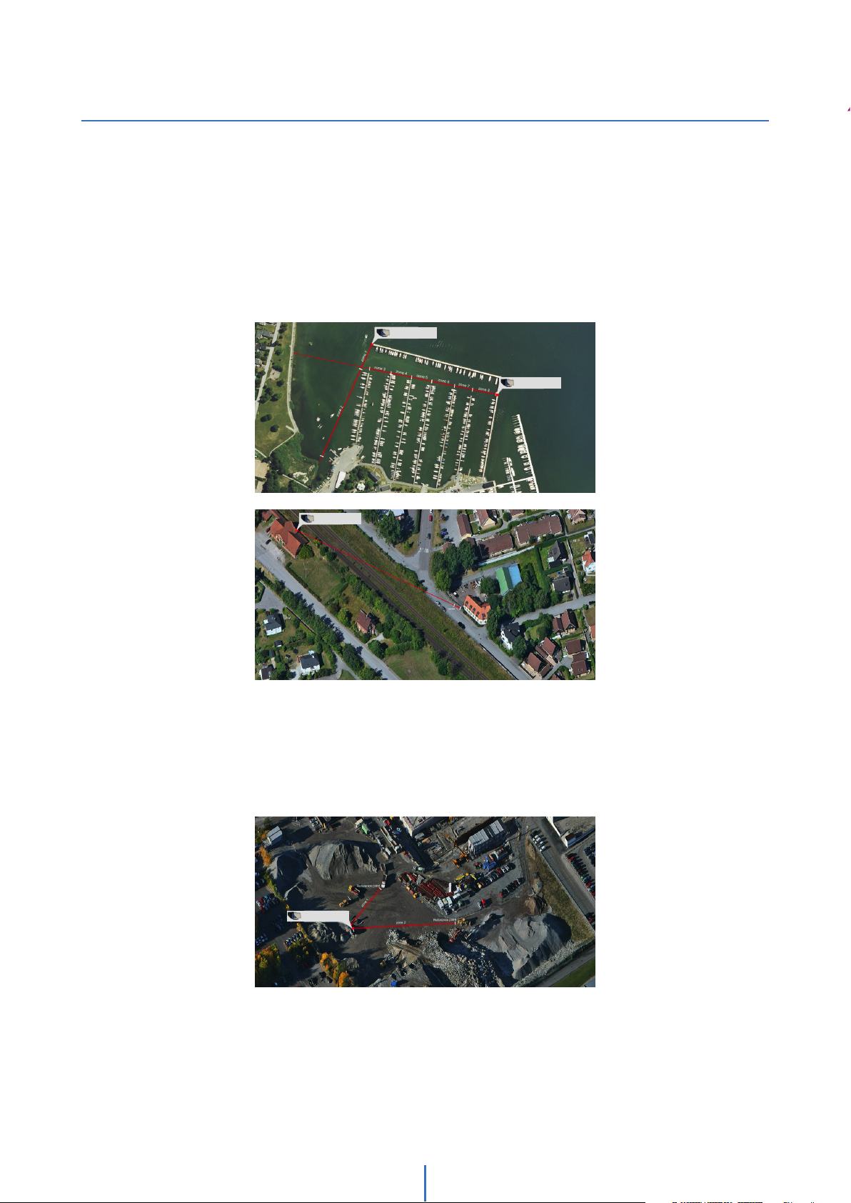
2.1. Detection methods
With fully adaptable alarm zones, the sensor has many detection methods customizable to any application. Below are
three typical applications.
2.1.1. Perimeter detection
The sensor is used to detect all objects crossing the virtual fence. Zones can be created along the line of sight to
permit dierent actions based on object location. For these types of applications, the sensor should be placed at the
optimal detection height and aligned with the ground.
SiteWatch™ sensor
SiteWatch™ sensor
SiteWatch™ sensor
2.1.2. Spot surveillance
Detection is only desired in a specific area (a part of a road, an entrance to a house or along a wall). In these
applications, the sensor can be located anywhere with a clear line of sight to the detection area.
SiteWatch™ sensor
2.1.3. Change detection
The sensor is used to detect if an object moves. In these applications, the sensor can be located anywhere with a clear
line of sight to the object.
6
Page 7

Operation Principles
3. OPERATION PRINCIPLES
3.1. Sensor placement
The sensor has a maximum detection range of 1640ft (500m). The recommended range for demanding
applications is 984ft (300m), to ensure detection of small objects such as humans, even in dicult weather
conditions.
There are two ways to create a continuous virtual fence with the sensors.
1. They can be placed 984ft (300m) apart and have an overlapping detection area as shown in figure A.
Sensor placement type A is recommended to get highest security level. With the overlapping detection areas, the
sensors cover each other.
2. They can be placed in pairs, with 1968.5ft (600m) between each pair, as shown in figure B. Sensor
placement type B allows for lower installation expense, with fewer points needing network connection. However,
it can create a weak point at the sensor’s locations.
NOTE: When placing the SiteWatch™ laser sensors opposite each other (as shown in B below), make sure
the lasers are crossed and not aimed directly at each other.
A
B
SiteWatch™ sensor
SiteWatch™ sensor
984ft (300m)
SiteWatch™ sensor SiteWatch™ sensorSiteWatch™ sensor
SiteWatch™ sensor
1968.5ft (600m)
SiteWatch™ sensor
SiteWatch™ sensor
3.2. Laser divergence
The laser has a beam divergence of 2.0x0.2 m Rad. It spreads more in height than in width. This means that the laser
beam is approximately 1 x 0.1m at a distance of 1640ft (500m).
SiteWatch™ sensor
3.28ft (1m)
1640ft (500m)
SiteWatch™ sensor SiteWatch™ sensor
SiteWatch™ sensor SiteWatch™ sensor
984ft (300m)
SiteWatch™ sensor SiteWatch™ sensor SiteWatch™ sensorSiteWatch™ sensor
984ft (300m)
3.3. Multiple reflections
As the laser beam diverges, it is possible for the beam to hit multiple targets. Each target will cause a reflection back
to the sensor. The sensor’s algorithm analyzes the dierent reflections and calculates the distance to the
object. If it is more than 16.4ft (5m) between the objects, the sensor will only use measurements from the far object to
calculate the object position. If for example, a tree branch partly covers the sensor’s line of sight. The laser may still be
able to detect objects behind it. It is, however, strongly recommended to ensure that the
sensor’s line of sight is clear to maintain the highest performance.
Calculated distance
SiteWatch™ sensor
16.4ft (5m)
7
Page 8

Operation Principles
If it is less than 16.4ft (5m) between the objects, the sensor will cluster the objects and use a weighted
averaging to calculate a virtual object position. If each object gets 50% of the laser beam, the calculated
distance will be in the middle between the objects. If the first object gets 75% and the other 25%, the calculated distance will move closer to the first object.
Calculated distance
SiteWatch™ sensor
> 16.4ft
(5m)
SiteWatch™ sensor
SiteWatch™ sensor
Calculated distance
> 16.4ft
(5m)
Calculated distance
> 16.4ft
(5m)
3.4. Alarm zones
Users can set up 20 separate alarm zones. Each zone has individual start- and stop-distance, alarm sensitivity and
alarm action.
SiteWatch™ sensor
Zone 1
Zone 2
Zone 3
Zone 4
Zone 5
Zone 6
Zone 7
Zone 8
Zone 9
Zone 10
Zone 11
Zone 12
Zone 13
Zone 14
Zone 15
Zone 16
Zone 17
Zone 18
Zone 19
Zone 20
Using all 20 zones can make it possible to have unique alarms for each 82ft (25m) sections of the sensor’s perimeter
if the zones are equally distributed. The sensor is also able to send the exact intrusion distance for even more accurate
location. In most cases, it is not recommended to have the zones equally distributed – it is better to set the zones to
match the surrounding area.
For example, if the detection area includes a crossing road, it is useful to create zones to match the road, as seen in
the example below.
SiteWatch™ sensor
Zone A
Zone B
Each zone in the SiteWatch™ laser sensor has an individual start- and stop-distance. This means the zones can overlap
in any way. It also means that only areas of interest will create alarms. It is also possible to have dierent alarm sensitivity for each zone, allowing for additional fine-tuning of the system.
SiteWatch™ sensor
Zone B Zone C Zone D
Zone A
8
Page 9

Combining the laser sensor with IP cameras
3.5. Combining the SiteWatch™ laser sensor with surveillance cameras
The SiteWatch™ laser sensor is designed to detect objects and alarm to a VMS software such as DW Spectrum®
IPVMS, or directly to an IP camera. With a dedicated detector, fewer cameras can be used since they can be
programmed to the exact location of an intrusion. The number of cameras required depends on camera type. Pantilt-zoom (PTZ) and multi-sensor cameras are recommended to use in combination with the SiteWatch™ laser sensor,
but fixed and vari-focal cameras can also be used. We recommend using fixed and vari-focal cameras for high-interest
locations, such as gates and entrances, and PTZ cameras for the rest of the area.
SiteWatch™ sensor
Multi-sensor camera Multi-sensor camera
SiteWatch™ sensor
PTZ camera PTZ camera
SiteWatch™ sensor
Fixed camera Fixed camera Fixed camera
9
Page 10

Combining the laser sensor with IP cameras
4. INSTALLATION AND ANGLE ADJUSTMENT
4.1. Alignment
The final alignment adjustment of the sensor is made with the adjustment screws on the side of the sensor. To
facilitate the alignment, horizontal and vertical adjustments must be completed separately.
Vertical
Alignment
Adjustment
Horizontal
Alignment
Adjustment
To align the sensor:
1. Remove the sensor’s shell.
2. Fasten the telescopic sight (optional) with the quick release mounts.
3. Release all adjustment screws using the included 2.5mm hex Allen wrench.
4. Use the screw on one side to push the sensor in the desired direction. 3/4 turns of the adjustment screws are
equal to 3.28ft (1m) movement at 328ft (100m), 6.56ft (2m) at 656ft (200m) and so on.
5. When the sensor is aligned, tighten the screws from both sides to lock the alignment into place.
6. Confirm that alignment is correct once all the screws have been tightened.
7. Replace the sensor’s shell.
4.2. Hardware reset
1. Remove the sensor’s shell and service lid.
2. Disconnect the network cable.
3. Press and hold the reset button, while reconnecting the network cable back.
4. Replace the sensor’s service lid and shell.
5. The unit will change its IP address back to the default IP address.
6. When accessing the unit using the web-based user interface, it will load the bootloader screen.
7. If there is any issue with the firmware, please restore factory firmware by pressing ‘Restore factory firmware’.
8. Press ‘Start firmware’ to restart the unit with the factory default IP address and login.
Reset button
10
Page 11

Web interface - Login
5. USER INTERFACE
All settings to the sensor can be made through the web-based user interface.
The instructions for the web-based user interface described below are valid for firmware 1.8 and higher.
5.1. FACTORY DEFAULT SETTINGS
When using the sensor for the first time, or if a factory reset has been made, the following settings are used:
Default IP address: 192.168.0.10
Default username: admin
Default password: admin
5.2. LOGIN
1. Open a web browser.
2. In the address field, type in the sensor’s IP address.
3. The web-based user interface login page will be shown.
4. Enter your username and password to access the sensor’s settings.
5.3. INSTALLATION AND CONFIGURATION
5.3.1. Alignment
1. Alignment is the default tab shown when logging into the sensor.
2. Turn on and o the alignment laser with the buttons on the bottom right. Remember to turn o the laser when
the installation process is complete.
3. The two diagrams on this page show live data from the sensor. The upper diagram shows data from the last 10
seconds. The second data from the last 60 seconds. Each diagram has three curves, representing the highest
value (green), average value (yellow) and lowest value (blue). This means the diagram displays rapid changes
accurately. It is also a good indication of the signal stability. A significant dierence between highest and lowest
values indicates an unstable reference point, such as tree branches.
4. To the right, the screen shows the sensor’s current distance, highest and lowest distance measured in the last 60
second and the current weather intensity.
11
Page 12

Web interface - Device configuration
5.3.2. Device configuration
1. Open the ‘Device configuration’ tab.
2. The sensor’s current network and user settings are shown.
3. To change TCP/IP settings, press ‘edit settings’ under the network settings. Input fields will appear to the right.
4. Modify the settings as needed and press the save button when done. If you change the sensor’s IP address, you
will have to reload the page with the new IP address.
5. To change current login settings, press ‘edit settings’ under the login section. Input fields will appear to the right.
6. Enter a new username and password.
7. Press the save button to confirm.
12
Page 13

Web Interface - Import & export settings
5.3.3. Import and export settings
Alarm settings can be exported as a file for backup and to copy settings to other sensors. IP address and login
settings are not included in the exported file.
1. Open the Import and export settings tab.
2. Export all current alarm settings by pressing the ‘Download’ button. Pay attention to the file location on your
hard drive. The file name is individual for each sensor as it includes the sensor’s MAC address.
3. To import a setting file, press ‘Choose File’ and navigate to the location of the previously saved setting file on
your hard drive.
4. When the file is selected, press the ‘Upload’ button. Pay attention to the status message next to the button.
Importing a setting file will overwrite all current settings.
13
Page 14

Web interface - Firmware update
5.3.4. Firmware update
The SiteWatch™ laser sensor’s firmware should be updated when new versions are available.
To update the sensor’s firmware:
1. Open the Firmware update tab. The sensor’s current firmware version is displayed.
2. Press the ‘Update firmware’ button to enter the system bootloader.
3. In the bootloader, you have the option to upload a new firmware, clear all settings (restore factory settings) and
restore to the factory firmware.
4. Press ‘Start firmware’ to start the laser sensor’s current firmware again.
5. Press ‘Clear settings’ to restore the unit to its factory settings.
6. Press ‘Restore factory firmware’ to restore the unit’s factory firmware.
7. To upload a new firmware, press ‘Choose File’ and navigate to the location of the firmware file on your hard drive.
When a file is selected, the file name will be displayed next to the button.
NOTE: Uploading a new firmware will erase all alarm and configuration settings.
8. Press ‘Upload’. When the firmware file is uploaded, the unit will reboot the system with the new firmware.
9. After a reboot the firmware settings page will be shown again.
10. Press Start firmware button to restart the Night Watch™ laser with the new firmware.
14
Page 15

Web interface - Alarm settings
5.4. ALARM SETTINGS
The SiteWatch™ laser has four types of alarms, zone alarms, reference point alarms, time/heartbeat alarms and
weather alarms. All alarms are designed for network communication, but the built-in relay can also be used.
5.4.1. Zone alarms
Zone alarms are standard alarms for object detection. Up to 20 zones can be created and each zone can have
individual settings and alarm actions.
1. Open the Alarm settings tab.
2. Press ‘+ Add zone’ to create a new alarm zone. Input fields will appear on the right.
3. Enter a zone name.
4. Under ‘near distance’, enter the distance at which the zone should start.
5. Under ‘far distance’, enter the distance at which the zone should end.
6. Click ‘Add alarm’ to save the settings.
The laser sensor also oers advanced alarm settings. These settings can be used to adapt the zones for special purposes. We recommend to thoroughly verify the function of the alarm zone if these settings are changed.
7. Press ‘Advanced settings’ to show the additional settings options.
8. Sensitivity: use the sensitivity bar to adjust the detection sensitivity. High sensitivity levels can be used for applications where highest detection is necessary. This may also increase the probability of false alarms. Low sensitivity can be used where the objects are big and slow (for example: detection of boats).
9. Delay: allow a zone alarm to react if an object has stopped in the zone. Enter the time for which an object must
stay in the zone before the alarm is activated. Default value is 0 seconds, maximum is 120 second (2 minutes).
10. Timeout: the time before a zone alarm resets once an object has been detected. This can be used to avoid extra
alarms from objects that may create multiple detections (for example: masts on a boat). Default value is 0 seconds, maximum is 120 seconds (2 minutes).
11. Speed limit: enter a speed limit which an object must travel before the alarm is activated. Enter in meters per
second.
Repeat the steps above for each new zone.
To edit a zone, press the zone name.
To remove a zone, press ‘Remove’ next to the zone name. The zone and all actions for the zone will be removed.
15
Page 16

Web interface - Alarm zones actions
5.4.2. Alarm zones actions
1. Press ‘+ Add action’ under the desired alarm zone. Input fields appear on the right.
2. Choose the action event type from the options in the drop-down menu. ‘Relay action’ and ‘Connect to URL’ are
available. For relay action, go to step 5.
3. If ‘Connect to URL’ is selected, enter the IP address to connect to, such as the VMS server.
4. Depending on the VMS, alarm disable URL may be needed.
5. Press the ‘Save’ button to confirm settings.
6. Repeat for each zone as needed.
7. To edit an action, press ‘Edit’ next to the action in the list.
8. To remove an action, press ‘Remove’ next to the action in the list.
16
Page 17

Web interface - Reference point
5.4.3. Reference point
Reference point alarm is a tampering alarm used to detect if the sensor has been moved or covered. Reference point
alarm is possible only when the laser sensor is aligned in a manner where there is a reference object and the signal
stability is good. To add a reference point alarm:
1. In the Alarm settings tab, click on ‘Add alarm’.
2. Select ‘Reference point’ from the ‘Input’ drop-down menu.
3. Enter the distance to a selected reference point in meters.
4. Enter the target variance, the maximum allowed change in distance relative to the reference point before the
alarm is triggered. Enter values in meters.
5. If applicable, enter a value for alarm delay. This indicates the time which the reference point must be faulty before
an alarm is activated. To avoid false alarms, the alarm delay should be significantly dierent from the time of a
standard object passage.
6. Press ‘Add’ to confirm the settings.
7. To create alarm actions for the reference point, press ‘+ Add action’. Input fields appear on the right.
8. Choose the action event type from the drop-down menu options.
9. Press ‘Save’ to confirm settings.
17
Page 18

Web interface - Timer / Heartbeat
5.4.4. Timer / Heartbeat
The timer / heartbeat is a tampering alarm used to detect a cable break or product malfunction by periodically sending a short message to the server.
To setup a timer / heartbeat alarm:
1. In the Alarm settings tab, click on ‘Add alarm’.
2. Select ‘Timer/heartbeat’ from the ‘Input’ drop-down menu.
3. Enter an alarm name for the new alarm.
4. Enter the time interval in seconds. This will indicate how often the system will send a short message to the server.
5. Click ‘Add alarm’ to save the new alarm settings.
To add an action for a timer/heartbeat alarm:
6. Click on ‘Add action’ under the alarm’s name.
7. Choose the action event type from the drop-down menu options.
8. Press ‘Save’ to confirm settings.
18
Page 19

Web interface - Weather alarm
5.4.5. Weather alarm
The laser sensor is constantly evaluating the measurement signal to determine the weather intensity at a scale from 0
to 10. This allows users to create alarm actions based on weather intensity.
1. In the Alarm settings tab, click on ‘Add alarm’.
2. Select ‘Weather alarm’ from the ‘Input’ drop-down menu.
3. Enter desired threshold level on weather intensity alarm (default is 1).
4. Enter a timeout value, the shortest time the weather alarm is active. Each time the weather intensity
exceeds the threshold, the timeout is reset. Default time is 10 minutes.
5. Press ‘Add’ to save the new alarm.
6. Create Alarm actions for the weather alarm by pressing “+ Add action”.
7. Choose action event type from the drop-down menu options.
Connect to URL
If the weather intensity threshold is exceeded, the unit alarms to the URL.
- Enter desired URL, for example the VMS server.
- Depending on VMS, alarm disable URL can be needed.
Relay action
Activates the internal relay.
Disable reference point
If the weather intensity threshold is exceeded, reference point alarms are ignored.
8. Press the Add action button to confirm settings.
5.5. LOGOUT
1. Press the ‘Logout’ button on the top right of the menu bar.
2. You will automatically be logged out of the sensor’s web user. The system will log o from all users connected
from any computer.
19
 Loading...