

Page 1
DWC-MBH2I4WV
MEGApix® Bullet Camera
Before installing or operating the camera, please read and follow this manual carefully.
08/18
Page 2

PRECAUTIONS
Do not open or modify.
Do not open the case except during maintenance and installation, for it may be dangerous and can cause
damages.
Do not put objects into the unit.
Keep metal objects and flammable substances from entering the camera. It can cause fire, short-circuits, or other
damages.
Be careful when handling the unit.
To prevent damages, do not drop the camera or subject it to shock or vibration.
Do not install near electric or magnetic fields.
Protect the camera from humidity and dust.
Protect the camera from high temperature.
Be careful when installing near the ceiling of a kitchen or a boiler room, as the temperature may rise to high levels.
Cleaning: To remove dirt from the case, moisten a soft cloth with a soft detergent solution and wipe.
Mounting Surface: The material of the mounting surface must be strong enough to support the camera.
FCC COMPLIANCE
This equipment has been tested and found to comply with the limits for a Class B digital device, pursuant to Part 15 of the
FCC rules. These limits are designed to provide reasonable protection against harmful interference, when the equipment
is operated in a residential environment. This equipment generates, uses, and radiates radio frequency energy, and if it is
not installed and used in accordance with the instruction manual, it may cause harmful interference to radio
communications.
WARNING: Changes or modifications are not expressly approved by the manufacturer.
2
Page 3

TABLE OF CONTENTS*
Introduction......................................................................................................................................................................4
Features.................................................................................................................................................................................................4
Parts .......................................................................................................................................................................................................5
Dimensions..........................................................................................................................................................................................6
Inside the Box ....................................................................................................................................................................................7
Installation........................................................................................................................................................................8
Network Connection ........................................................................................................................................................................8
Before Installation .............................................................................................................................................................................9
Installation ..........................................................................................................................................................................................10
MEGApix® 1080p™ Camera Setup................................................................................................................................11
Installing DW Desktop Tool™ ........................................................................................................................................................11
Using DW Desktop Tool™ ........................................................................................................................................................12-14
Network Options..............................................................................................................................................................................15
Camera Reboot.................................................................................................................................................................................16
MEGApix® 1080p™ Camera Web Viewer....................................................................................................................17
Accessing the Camera’s Web Viewer......................................................................................................................................17
GUI Description ...............................................................................................................................................................................18
First & Second Stream...................................................................................................................................................................19
MEGApix® 1080p™ Camera Setup..............................................................................................................................20
Local Configuration .....................................................................................................................................................................20
Basic > System Settings..........................................................................................................................................................21-23
Basic > Network Settings ......................................................................................................................................................24-26
Basic > Stream Settings .........................................................................................................................................................27-28
Basic > Image Settings ..........................................................................................................................................................29-32
Basic > Security ..............................................................................................................................................................................33
Advanced > Image ........................................................................................................................................................................34
Advances > Security ...............................................................................................................................................................35-38
Advanced > Basic Event .......................................................................................................................................................39-43
Specifications ..........................................................................................................................................................44-45
Troubleshooting .....................................................................................................................................................46-49
Warranty........................................................................................................................................................................50
Limits & Exclusions.......................................................................................................................................................51
3
Page 4

FEATURES*
1/3” CMOS Image Sensor
Real-time 2.1MP Resolution, 1080P at 30fps
Dual Codecs (H.264, MJPEG) with Simultaneous Streaming
4.0mm Fixed Lens
Smart IR™ with Intelligent Camera Sync. 100ft Range
Smart DNR™ 3D Digital Noise Reduction
Digital Wide Dynamic Range (DWDR)
True Day/Night Mechanical IR Cut Filter
Auto Gain Control (AGC)
Back Light Compensation (BLC)
Auto White Balance (AWB)
Programmable Privacy Zones
Motion Detection
Web Server Built-in
PoE and DC12V
OnVIF Compliant, Profile S
IP66 Certified (Weather Resistant)
4
Page 5
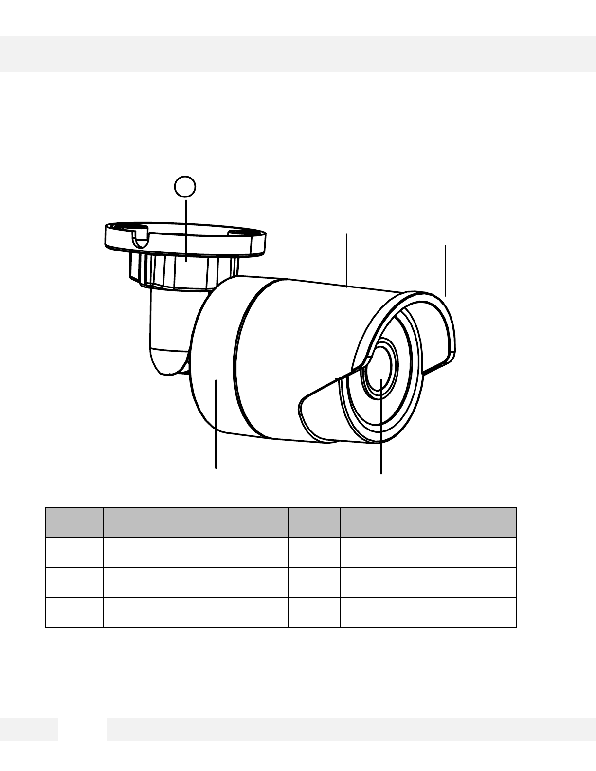
PARTS & DESCRIPTIONS*
No. Description
No
.
Description
1 Mounting Base 4 Lens
2 Back Box 5 Sun Shield
3 Front Box
5
Page 6
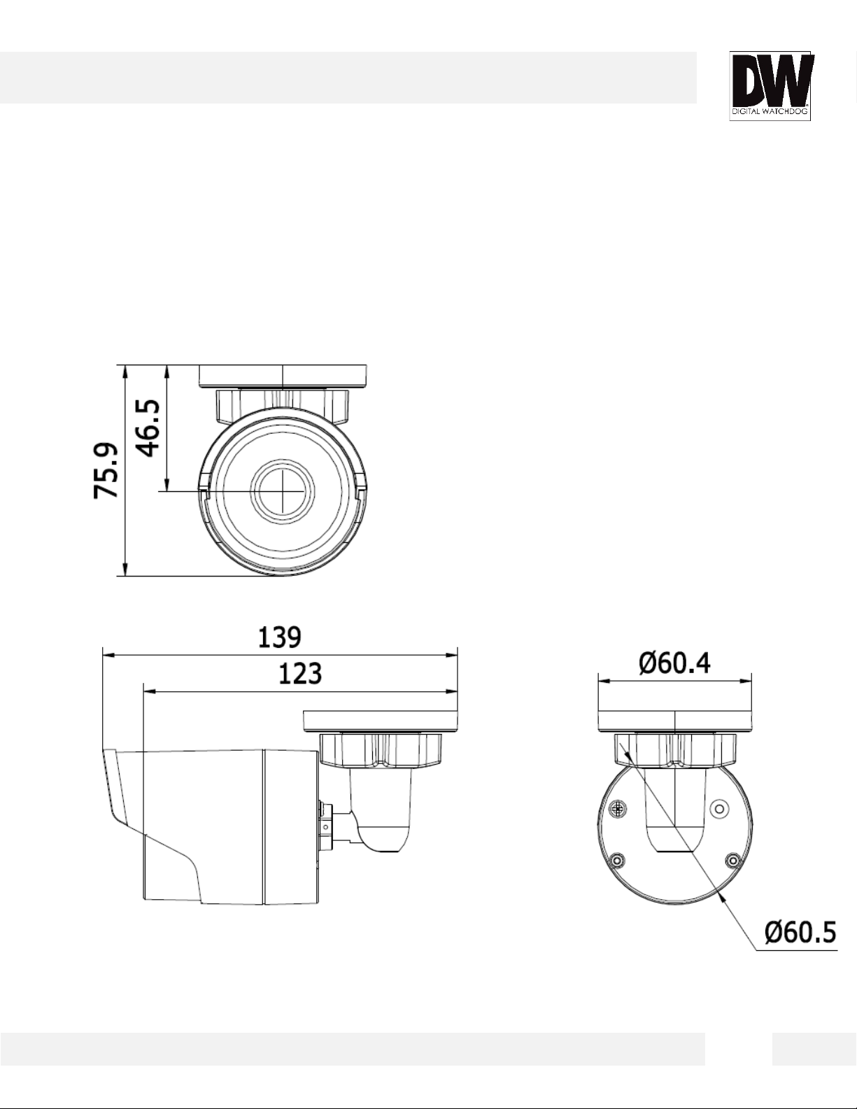
DIMENSIONS*
6
Page 7
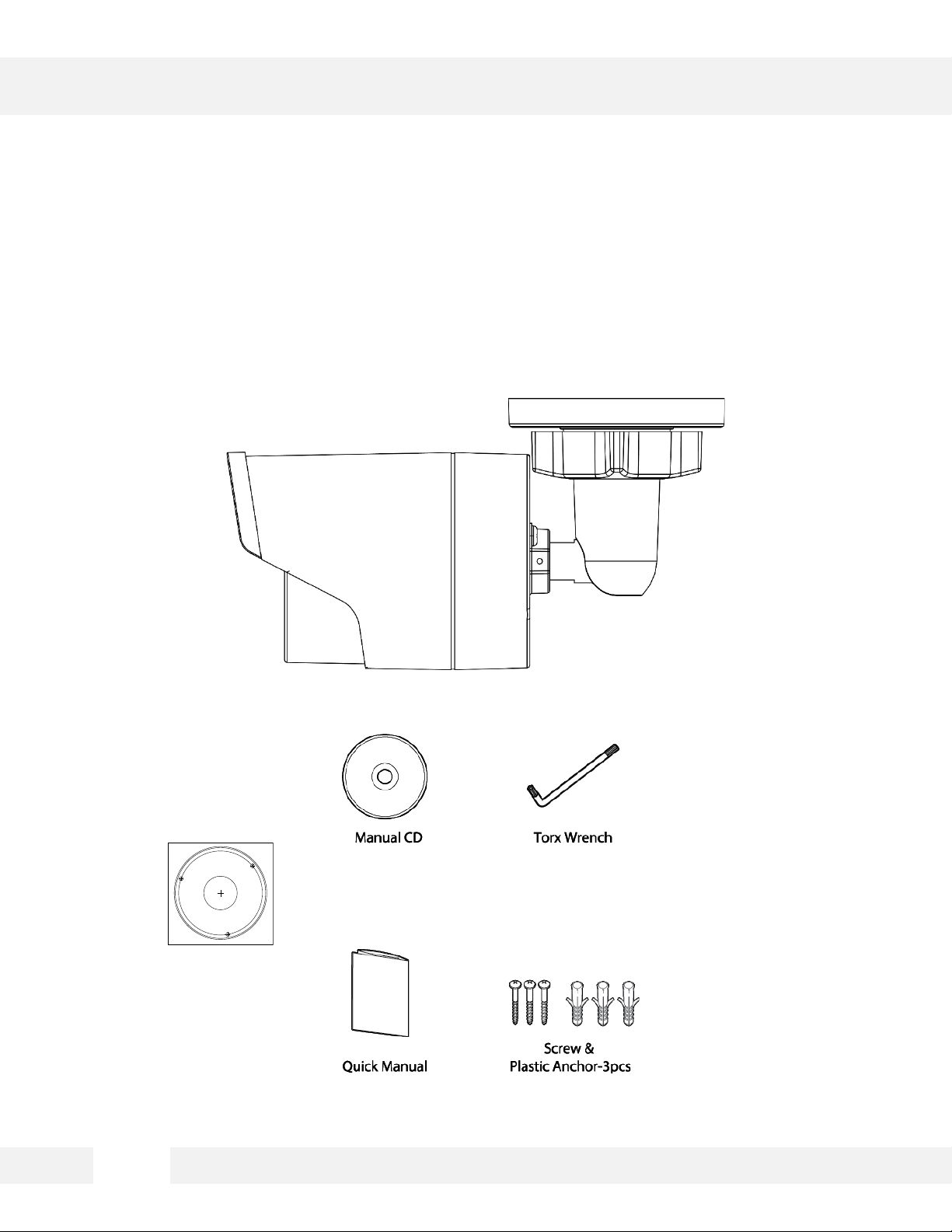
INSIDE THE BOX *
Drill Template
Hole A: for cables routed through the ceiling
screw hole 1: for Mounting Base
1
1
1
A
The following items are included with the MEGApix® 1080p™ camera.
Mounting Template
7
Page 8
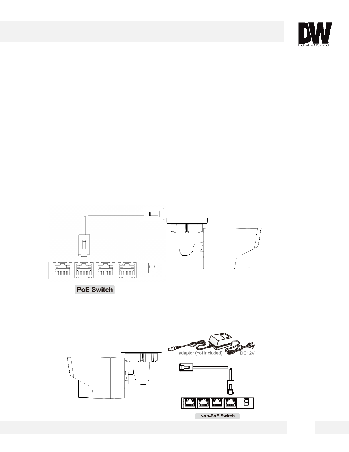
NETWORK CONNECTION*
There are two ways to power a MEGApix® 1080p™ camera.
Use a PoE- enabled switch to connect data and power through a single
cable to begin viewing and recording images instantly. A non- PoE switch
will require an adaptor for power transmission.
1. Using a PoE-Enabled Switch
The MEGApix® 1080p™ Camera is PoE-Compliant, allowing transmission of power and data via a
single Ethernet cable. PoE eliminates the need for the different cables used to power, record, or
control the camera. Follow the illustration below to connect the camera to a PoE-enabled switch
using an Ethernet cable.
2. Using 12VDC
If a PoE injector is not available, use a power adaptor for power transmission and a non-PoE switch
for data transmission. Follow the illustrations below to connect the camera without a PoE Injector.
8
Page 9

INSTALLATION*
Before Starting the Installation
Make sure the device in the package is in good condition and all the assembly parts are
included.
The standard power supply is 12V DC, please make sure your power supply matches with
your camera.
Make sure all the related equipment is power-off during the installation.
Check the specification of the products for the installation environment.
Make sure that the wall is strong enough to withstand four times the weight of the camera and
the bracket.
For the camera that supports IR, you are required to pay attention to the following precautions
to prevent IR reflection:
Dust or grease on the dome cover will cause IR reflection. Please do not remove the dome
cover film until the installation is finished. If there is dust or grease on the dome cover, clean
the dome cover with clean soft cloth and isopropyl alcohol.
Make sure that there is no reflective surface too close to the camera lens. The IR light from
the camera may reflect back into the lens causing reflection.
The foam ring around the lens must be seated flush against the inner surface of the bubble to
isolate the lens from the IR LEDS. Fasten the dome cover to camera body so that the foam
ring and the dome cover are attached seamlessly.
9
Page 10
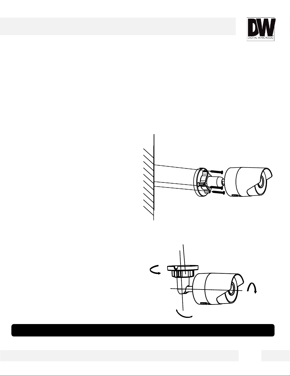
INSTALLATION*
0°~90°
Adjust Nut
0°~360
°
0°~360°
Installing the Camera
1. Use the mounting plate or camera itself to mark and drill
the necessary holes in the mounting surface.
2. Pull wires through and make connections.*
3. Adjust the camera’s tilting angles to adjust the camera’s
view. See the next page for more information.
Installing the Camera’s Angle
1. Loosen the adjustable nut.
2. Adjust the pan direction [0°~360°].
3. Adjust the tilt direction [0°~90°].
4. Rotate the camera [0~360°] to adjust the lens to the
surveillance angle.
5. Tighten the adjustable nut to complete
the installation.
* NOTE: If necessary, you can route cables through the side opening on the camera’s side
10
Page 11
DW Desktop Tool™ *
Installing DW Desktop Tool™ Software
DW Desktop Tool™ searches for all available Digital Watchdog devices
currently connected to your network.
1. Install DW Desktop Tool to find the MEGApix® 1080p™ camera on your local network. The
software can be found on the included User Manual CD. Run DW Desktop Tool and install onto
your PC.
2. When setup is complete, launch DW Desktop Tool.
3. The software will automatically search your network for all Digital Watchdog® supported devices.
Your camera will appear as ”DWC-MBH2I4WV.”
4. Double-click on the camera name and select ‘View Camera Website’ to launch the camera’ web
viewer.
*Install the DW Desktop Tool to a computer located on the same Subnet Mask as the MEGApix®
1080p™ camera.
11
Page 12
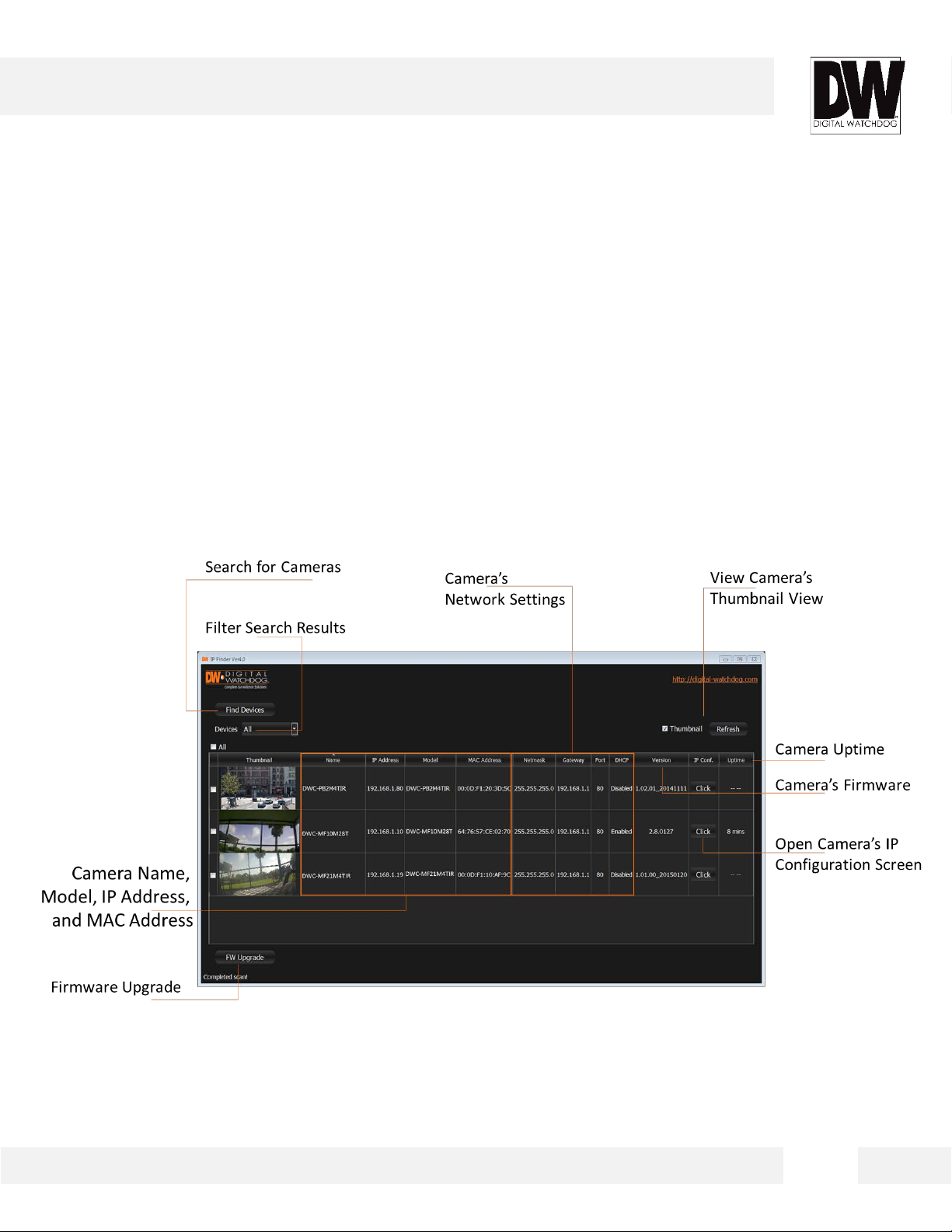
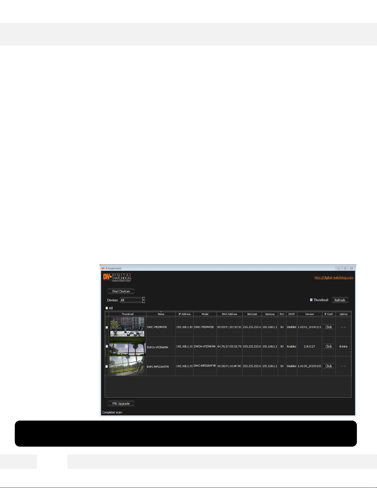
DW Desktop Tool™ *
Using DW Desktop Tool™ Software
Use DW Desktop Tool™ to change the basic settings of your MEGApix®
1080p™ camera, update firmware for multiple cameras simultaneously or
connect to your MEGApix® 1080p™ camera.
12
Page 13
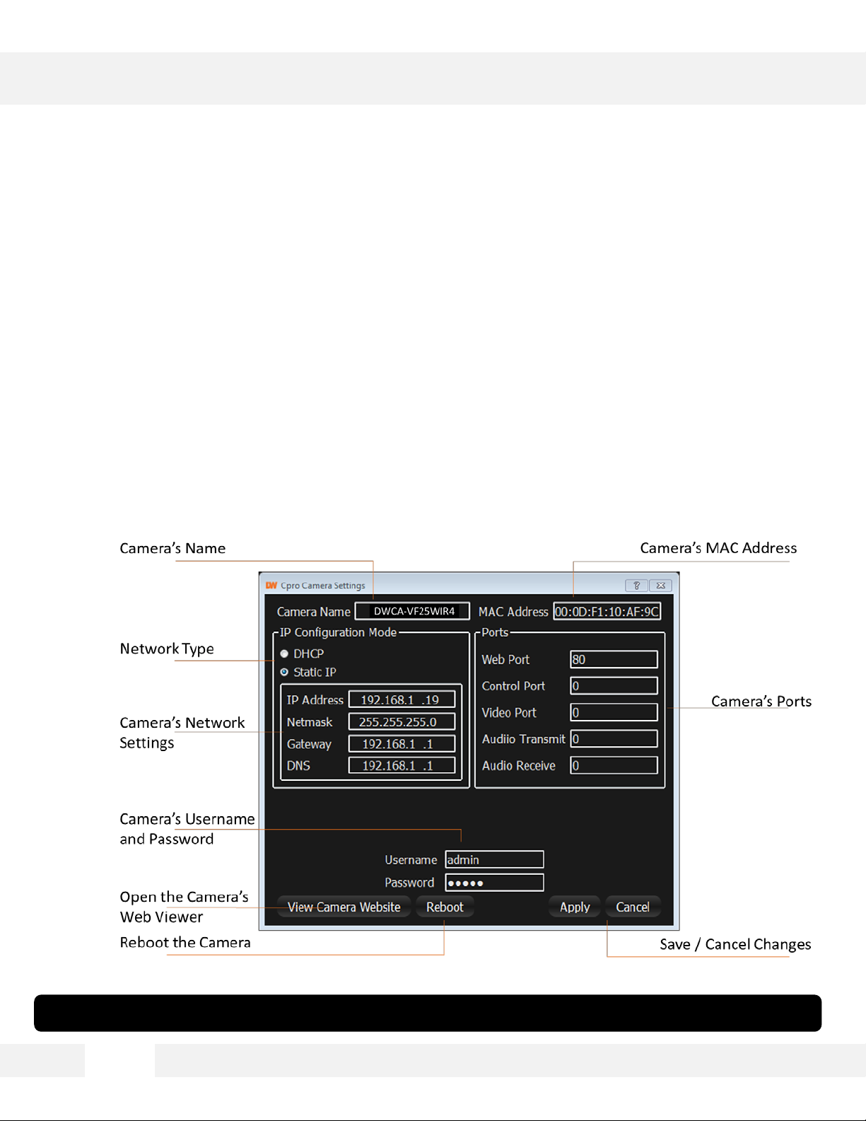
DW Desktop Tool™ *
Using IP Finder Software
Use IP Finder to set the connection type and the IP address information
for your MEGApix® 1080p™ camera.
1. DHCP: Select DHCP to access the camera within the same internal network. For further
explanation on DHCP, please see page 16.
2. Static IP: Select Static to connect to the camera from an external network. For further
explanation on Static, please see page 16.
*If you change the camera’s IP, write down the camera’s MAC Address for identification in the future.
13
Page 14

DW Desktop Tool™ *
DHCP
The Dynamic Host Configuration Protocol (DHCP) is a network configuration protocol that allows a
device to configure automatically according to the network it is connected to.
If your network supports DHCP and your MEGApix® 1080p™ camera is set to DHCP, IP Finder will
automatically find and set your MEGApix® 1080p™ camera to correspond with your network
requirements.
Static
Static IP addresses are recommended when using a network that does not support DHCP or when
setting your device to be accessed externally via the internet. If Static is selected, you must manually
enter the correct network settings for your MEGApix® 1080p™ camera. The settings will correspond
with your network. To set your camera to a static IP address, we recommend that you (1) setup the
camera to DHCP, (2) allow it to configure itself according to your network, and (3) change the settings
to a static IP address.
1. To set your MEGApix® 1080p™ camera to Static, highlight the desired device from the search
results list, and click on Configuration. In the “Network Configuration” window, make sure Static
is selected.
2. Enter the following information: IP Address, Netmask, Gateway, and Preferred DNS.
3. Click Apply and Reboot to save all changes.
14
Page 15
DW Desktop Tool™ *
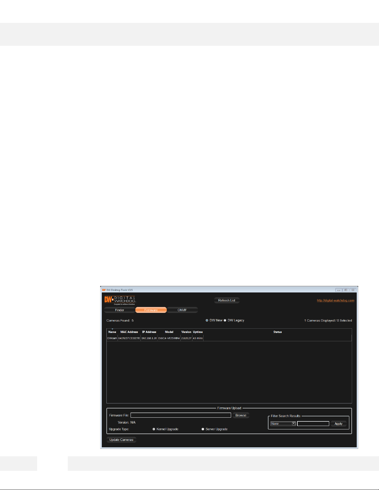
Upgrading Cameras using the DW Desktop Tool
Use the DW Desktop Tool™ to perform firmware upgrade to all your
MEGApix® 1080p™ cameras from one convenient location.
1. Press the ‘Firmware’ button.
2. In the Firmware Upload section, browse and select the appropriate firmware file to use.
3. Select all the cameras you would like to upgrade. You can select multiple cameras by clicking
on multiple camera models while holding down the Ctrl button*.
4. Click ‘Update Cameras’.
5. The system will indicate if the upgrade was successful or not for each camera.
6. When all cameras have been upgraded, restart the cameras to apply the new firmware.
7. Allow up to 60 seconds for the cameras to reboot and press the ‘Search’ button. If the cameras
reappear in the IP Finder the reboot is complete and the camera is ready.
15
Page 16
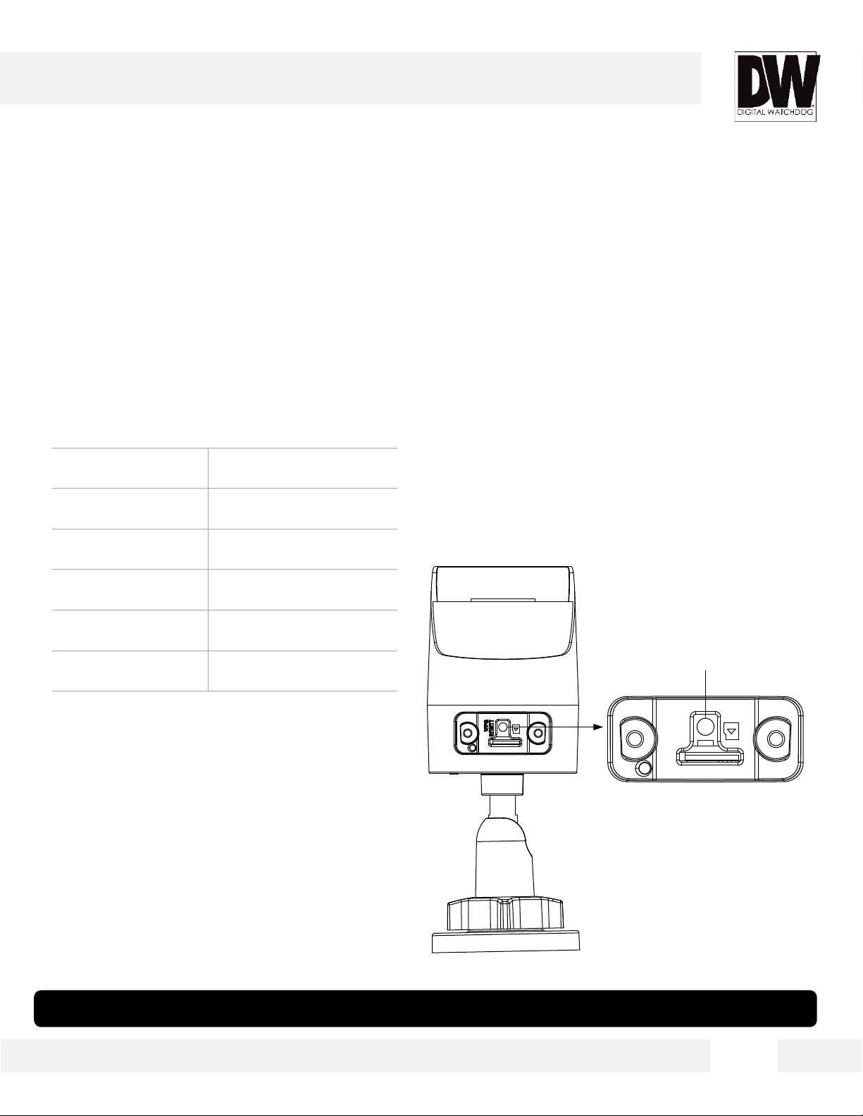
CAMERA REBOOT*
Resetting the Camera
Press RESET about 10s when the camera is powering on or rebooting to
restore the default settings, including the user name, password, IP
address, port No., etc.
The following are the default network settings.
IP Mode DHCP
IP Address 169.254.X.X
Subnet Mask 255.255.255.0
Gateway 169.254.X.X
HTTP Port 80
RTSP Port 554
* Frequent use may cause system error.
16
Page 17

WEBVIEWER*
Remote Video Monitoring Via Internet Explorer
Monitor and configure the MEGApix® 1080p™ camera through a built- in
web viewer.
1. Type the IP address of the camera in an Internet Explorer window.
Enter Username and Password (Default: Username: admin | Password: admin)
2. The web browser may ask to install the camera’s plug-in in order to view video. Once it has
been installed, Internet Explorer will display video images from the camera.
System Requirements:
• Operating System: Microsoft Windows XP SP1 and above / Vista / Win7 / Server 2003 / Server
2008 32bits
• CPU: Intel Pentium IV 3.0 GHz or higher
• RAM: 1G or higher
• Display: 1024×768 resolution or higher
• Web Browser:
Internet Explorer 6.0 and above
Apple Safari 5.02 and above
Mozilla Firefox 3.5 and above
Google Chrome8 and above
* The camera currently does not support 64-bit Google Chrome view.
17
Page 18

WEBVIEWER*
GUI Description
Monitor and configure the MEGApix® 1080p™ camera through a built- in
web viewer.
1. Live video display- This is the region for live video stream from the camera.
2. Setup- Setup the camera’s Video, Network, Events, System etc.
3. Stream Selection- Select a stream to display it in the viewing area.
4. Full Screen- Expand the camera’s view into full screen. To exit full screen view, press the Esc
button.
5. Menu options such as PTZ will be disabled for cameras that do not support those functions.
Video Display
Setup Menu
Stream Selection
Full Screen View
18
Page 19

WEBVIEWER*
First Stream & Second Stream
Configure up to two (2) stream settings for monitoring and recording.
On the main monitoring page, user can view the camera with the First Stream settings or secondary
Stream settings. The camera supports the setup of up to two (2) different streams with different
resolution, and FPS for maximum network control. Select which stream to view in the camera’s main
menu by selecting one of the options from the drop-down menu. Streams that are not enabled in the
Streams Setup page will not appear in the drop-down menu.
For Setup Stream Settings, refer to page 27.
Stream Selection
19
Page 20

WEBVIEWER*
SETUP > LOCAL CONFIGURATION
Setup the camera’s Protocol and Live Performance Options.
Protocol: On this page, you can update the camera’s streaming protocol. By default, the camera is set to
TCP.
• TCP: Ensures complete delivery of streaming data and better video quality. Real-time transmission
may be affected.
• UDP: Provides real-time audio and video streams.
• MULTICAST: Select this option when ‘Enable Multicast Discovery’ is checked in the Network setup
page. See page 25 for more information.
• HTTP: Allows the same quality as of TCP without setting a specific ports for streaming under some
network environments.
• Live View Performance: You can adjust the live streaming from the camera. Select between the
shortest delay or Auto. If auto is selected, buffering may occur when the network bandwidth is limited.
20
Page 21

WEBVIEWER*
SETUP > BASIC CONFIGURATION > SYSTEM > DEVICE
INFORMATION
View the camera’s basic information.
• Device Name: You can rename the camera as needed. By default, the camera’s model will be the
camera’s name.
• Model: Displays the camera’s model name (DWC-MBH2I4WV)
• Firmware and Encoding Version: View the camera’s current firmware and encoding versions. To
update the camera’s firmware, see page 23 ‘Maintenance’.
• Number of Channels: Displays the camera’s number of channels.
21
Page 22

WEBVIEWER*
SETUP > BASIC CONFIGURATION > SYSTEM > TIME
SETTINGS
Set the camera’s date and time.
It is recommended to set the camera’s date and time during the first time you operate the camera to
avoid time zone confusions on recorded data.
• Time Zone: Select the appropriate time zone from the drop-down options.
Time Sync: The camera can be set to synchronize its date and time with an external time sync server or
you can set the camera’s date and time manually.
• NTP Sync: If selected, enter the URL and port information for the time server you wish to use. The
camera will contact the server in the time intervals set in the Interval value (in seconds) and
synchronize its time and date with the server.
• Manual Time Sync.: If selected, enter manually the time and date for the camera. You can also select
to synchronize the camera’s date and time with the current computer.
22
Page 23

WEBVIEWER*
SETUP > BASIC CONFIGURATION > SYSTEM >
MAINTENANCE
Use this menu option to reboot the camera, reset and update firmware.
The maintenance menu tab allows you to conveniently reboot the camera, reset the settings and
update the camera’s firmware.
• Reboot: power cycle the camera. Please note. If the camera’s network settings are set to DHCP, the
camera’s IP address may change after boot up.
• Restore: All settings except for the network and user information will be reset to its factory default.
• Default: All settings, including the network and user settings will be reset.
• Firmware Update: To update the camera’s firmware:
1. Select firmware or firmware directory to locate the upgrade file.
a. Firmware: Locate the exact path of the upgrade file.
b. Firmware Directory: Only the directory the upgrade file belongs to is required.
2. Click the ‘Browse’ button and select the firmware file and press the ‘Upgrade’ button.
Please note that the upgrade may
take up to ten (10) minutes. Do not
disconnect the camera’s power
supply during the upgrade process.
Once the firmware upgrade is
complete, the camera will reboot.
23
Page 24

WEBVIEWER*
SETUP > BASIC CONFIGURATION > NETWORK > TCP/IP
Use this menu option to setup the camera’s network settings.
Set the camera’s IP address, subnet mask, gateway and DNS server information. If applicable, you can
also setup the camera for multicast.
• NIC Type: Select the network card associated with the camera. The default value is Auto.
• DHCP: Check if you are using a DHCP network and wish for the camera to obtain all the network
settings automatically from the DHCP server. If this box is checked, the fields for the network settings
below will not be editable.
If you wish to enter the camera’s network settings manually, make sure the DHCP is unchecked and
enter the following information:
• IPv4 / IPv6: If necessary you can setup both IPv4 and IPv6 network settings
• IP Address – Enter an IP address for the camera
• Netmask – default is 255.255.255.0
• Gateway – This is your router’s external IP address. This address is used when accessing the camera
remotely from outside the network. The router will channel the data request to the appropriate port
associated with the camera.
24
Page 25

WEBVIEWER*
SETUP > BASIC CONFIGURATION > NETWORK > TCP/IP
Use this menu option to setup the camera’s network settings.
Set the camera’s IP address, subnet mask, gateway and DNS server information. If applicable, you can
also setup the camera for multicast.
• MAC Address: shows the camera’s mac address.
• MTU: If applicable, you can enter the MTU setting value. The valid value range of MTU is 1280 ~
1500.
• Multicast Address: If you are using the Multicast protocol, you can enter a separate multicast address.
The Multicast sends a stream to the multicast group address and allows multiple clients to acquire the
stream at the same time by requesting a copy from the multicast group address. Before utilizing this
function, make sure the Multicast function is enabled on your router.
• Enable Multicast Discovery: Check the checkbox of Enable Multicast Discovery, and then the online
network camera can be automatically detected by client software via private multicast protocol in the
LAN.
• DNS Server – Enter a DNS address. The Domain Name Server translates a web addresses to an IP
addresses. You can enter up to two (2)
servers.
• Once all settings are adjusted, save all
changes. The camera will reboot to
apply the new network settings.
25
Page 26

WEBVIEWER*
SETUP > BASIC CONFIGURATION > NETWORK > PORT
Use this menu option to adjust the camera’s network ports as needed.
Set the HTTP port, RTSP port, HTTPS port and server port of the camera.
• HTTP Port: The default port number is 80, and it can be changed to any port No. which is not
occupied.
• RTSP Port: The default port number is 554 and it can be changed to any port No. ranges from 1024 to
65535.
• HTTPS Port: The default port number is 443, and it can be changed to any port No. which is not
occupied.
• Server Port: The default server port number is 8000, and it can be changed to any port No. ranges
from 2000 to 65535.
• Once all settings are adjusted, save all changes. The camera will reboot to apply the new port
settings.
26
Page 27

WEBVIEWER*
SETUP > BASIC CONFIGURATION > STREAM SETTINGS
Use this menu option to adjust the camera’s first and second streams.
The camera supports two simultaneous streams. The main stream is usually for recording and live
viewing with good bandwidth, and the secondary stream can be used for live viewing when the
bandwidth is limited.
• Stream Type: Select the first (main) stream or Secondary stream. The one selected will be the one you
can adjust the settings for. The main stream is usually for recording and live viewing with good
bandwidth, and the secondary stream can be used for live viewing when the bandwidth is limited.
• Resolution- Set Resolution for each stream. The better the resolution, the more bandwidth it will
require to stream images.
• Bitrate Type: Set the bitrate type as variable or constant.
• Video Quality: If the bitrate is set to variable, set the camera’s video quality.
• Frame Rate- Select from 1/16fps to 30fps. The camera is set by default to 30fps. The frame rate
describes the frequency at which the video stream is updated. A higher frame rate is preferred when
there is movement in the video
stream, as it maintains image quality.
27
Page 28

WEBVIEWER*
SETUP > BASIC CONFIGURATION > STREAM SETTINGS
Use this menu option to adjust the camera’s first and second streams.
The camera supports two simultaneous streams. The main stream is usually for recording and live
viewing with good bandwidth, and the secondary stream can be used for live viewing when the
bandwidth is limited.
• Max Bitrate: Set the max. bitrate to 32 ~ 16384 Kbps. The higher the value, the higher the video
quality. However, higher max bitrate will require higher bandwidth.
• Video Encoding: Select the type of compression to use when outputting the video. The compression
type affects the image quality, bandwidth, and file size of saved images. MJPEG, the lowest
Compression type, will provide the highest image quality, but also will cause the image size to be the
largest, and take up the most bandwidth. H.264 Baseline Profile is the default codec. The main
stream is set by default to H.264. The secondary stream can be set to either H.264 or MJPEG.
• I-Frame Interval: Set the I-Frame intervals from 1 ~ 400.
28
Page 29

WEBVIEWER*
SETUP > BASIC CONFIGURATION > IMAGE > DISPLAY
SETTINGS
Use this menu option to adjust the camera’s view.
The camera’s image can be adjusted according to the lighting environment in which it is installed. If
necessary, use this menu to adjust the camera’s Day/Night settings, exposure, DNR, etc..
• Switch Day and Night: Day/Night scheduled-switch configuration allows you to set separate camera
parameters for day and night switch, guaranteeing image quality in different illumination.
1. Set the start and end time for the switch schedule.
2. Click Common tab to configure the common parameters applicable to the day and night modes.
3. Click the Day tab to configure the parameters applicable for day mode.
4. Click the Night tab to configure the parameters applicable for night mode.
Image Settings:
a. Brightness ranges from 1~100. Default value is 50.
b. Contrast ranges from 1~100.
Default value is 50.
c. Saturation describes the
colorfulness of the image color.
Range from 1~100. Default value is 50.
d. Hue describes the warmth of the
colors of the image. Ranges from 1~100.
The higher the number, the camera’s
image will use warmer tones. The lower
the number, the camera’s image will use
cooler color tones. Default value is 50.
d. Sharpness describes the edge
contrast of the image. Ranges from 1~100,
and the default value is 50.
29
Page 30

WEBVIEWER*
SETUP > BASIC CONFIGURATION > IMAGE > DISPLAY
SETTINGS
Use this menu option to adjust the camera’s view.
The camera’s image can be adjusted according to the lighting environment in which it is installed. If
necessary, use this menu to adjust the camera’s Day/Night settings, exposure, DNR, etc..
• Exposure Settings
a. Iris Mode: This camera is equipped with a fixed 4.0mm lens. Therefore the Iris mode is set to
manual by default.
b. Exposure Time: Select the shutter speed from 1/3~1/100000. The default is 1/30.
c. Gain
• Day/Night Settings: Select the day/night switch mode, and configure the smart IR settings from this
option.
a. Day/Night Settings:
Day: the camera stays in day mode.
Night: the camera stays in night
mode.
Auto: the camera switches between
the day night mode according to
the level of light in the camera’s
scene. If Auto is selected, adjust the
sensitivity and filter time.
The sensitivity ranges from 0~7.
The higher the value is, the easier
the camera will switch modes.
The filtering time refers to the time
between the day/night switch. Set it
from 5s to 120s.
Schedule: Set the start time and
end time for the day/night duration.
b. Smart IR: Smart IR: adjust the power
of the IR LED, providing a clear image
that is not overexposed or too dark.
30
Page 31

WEBVIEWER*
SETUP > BASIC CONFIGURATION > IMAGE > DISPLAY
SETTINGS
Use this menu option to adjust the camera’s view.
The camera’s image can be adjusted according to the lighting environment in which it is installed. If
necessary, use this menu to adjust the camera’s Day/Night settings, exposure, DNR, etc..
• Backlight Settings
a. BLC Area: If you focus on an object against strong backlight, the object will be too dark to be seen
clearly. BLC compensates light to the object in the foreground to make it clear. If enabled, select the
area in the camera’s view to apply the BLC mask. Select from: Up, Down, Left, Right and Center.
b. WDR: Wide Dynamic Range can be used when there is a high contrast of the bright area and the
dark area of the scene.
• White Balance: This gives the camera a reference to “true white.” White Balance is used to make
colors appear the same in the Field of View (FoV) no matter what is the light temperature of the light
source. Select form the available
drop-down menu options.
31
Page 32

WEBVIEWER*
SETUP > BASIC CONFIGURATION > IMAGE > DISPLAY
SETTINGS
Use this menu option to adjust the camera’s view.
The camera’s image can be adjusted according to the lighting environment in which it is installed. If
necessary, use this menu to adjust the camera’s Day/Night settings, exposure, DNR, etc.
• Noise Reduction
a. Digital Noise Reduction: Control the level of noise in the image. If enabled, adjust the level of noise
reduction.
b. Noise Reduction Level: Set the DNR level from 0~100, and the default value is 50.
• Video Adjustment:
a. Mirror: It mirrors the image so you can see it inversed. Left/Right, Up/Down, Center, and OFF are
selectable
b. Rotate: To make a complete use of
the 16:9 aspect ratio, you can enable
the rotate function when you use the
camera in a narrow view scene.
When installing, turn the camera 90
degrees or rotate the 3-axis lens to
90 degrees, and set the rotate mode
on. You will get a normal view of the
scene with 9:16 aspect ratio.
c. Video Standard: 50 Hz and 60 Hz
are selectable. Choose according to
the different video standards.
32
Page 33

WEBVIEWER*
SETUP > BASIC CONFIGURATION > SECURITY > USER
Use this menu option to add, edit, or delete users.
The camera can be accessed by different user levels, with different permissions and access to allow for
maximum security, preventing people from accessing the camera’s sensitive information.
The admin user cannot be deleted and you can only change the admin password.
• To add a user:
• 1. Click the ‘Add’ button.
2. Enter a username and password for the new user.
3. Set the user’s Access level. Select from:
a. Operator: granted access to the camera’s advanced settings
b. User: granted basic access to the camera’s video and information.
4. Check the box next to each permission granted to this user.
• To edit a user:
1. Select a user from the use list.
2. Click ‘Modify’.
3. Adjust the necessary permissions
or password.
4. Click OK to save.
• To delete a user:
1. Select a user from the use list.
2. Click ‘Delete’.
3. Click OK to confirm.
33
Page 34

WEBVIEWER*
SETUP > ADVANCED CONFIGURATION > IMAGE > PRIVACY
MASK
This menu allows you to setup privacy masks over sensitive regions of the
camera’s FoV.
Privacy mask enables you to cover certain areas on the live video to prevent certain spots in the
surveillance area from being live viewed and recorded.
• To add a privacy mask:
1. Check the ‘Enable Privacy Mask’ button.
2. Click on the ‘Draw Area’ button.
3. Click and drag the mouse in the live video window to draw the mask area. You can draw up to four
(4) masks.
5. Click ‘Stop Drawing’ to finish drawing
6. Click ‘Clear All’ to clear all of the areas you set without saving them.
34
Page 35

WEBVIEWER*
SETUP > ADVANCED CONFIGURATION > SECURITY>
AUTHENTICATION
This menu allows you to setup a secured live stream from the camera.
This advanced feature adds a layer of security to the camera’s RTSP stream. If you disable the RTSP
authentication, anyone can access the video stream using the RTSP protocol via the IP address.
• Select the RTSP Authentication type from the drop-down list to enable or disable the RTSP
authentication.
• Click Save to save the settings.
35
Page 36

WEBVIEWER*
SETUP > ADVANCED CONFIGURATION > SECURITY>
ANONYMOUS VISIT
This setup allows user with no user name and password to access the
camera.
By permitting the Anonymous “Live View” function, you may enable others to access your camera and
view live images without providing login credentials.
• Select to enable or disable the anonymous visit function from the drop-down menu options.
• If enabled, an Anonymous option will be added to the login screen.
• To use the Anonymous login feature, check the box next to ‘Anonymous’ and click on the Login
button. There will be no need to enter a username or password and you will be able to view live
streaming from the camera.
NOTE: It is critical when permitting the Anonymous "Live View" function to ensure that your camera's
field of view does not impact the privacy of individuals whose images might be captured without
authorization.
36
Page 37

WEBVIEWER*
SETUP > ADVANCED CONFIGURATION > SECURITY> IP
ADDRESS FILTER
Use this menu to filter what IP addresses are forbidden or permitted to
access the camera.
This function allows you to control the access to your camera by entering specific IP addresses to the
list of permitted or prohibited addresses.
• To use the IP Address Filter:
1. Check the box next to ‘Enable IP Address Filter’.
2. Select the type of IP address you are about to input as Forbidden or Allowed.
3. Click on the ‘Add’ button and enter the IP address.
4. The IP address will be added to the table below.
• To modify an IP Address:
1. Click on the IP address from the table.
2. Click on the ‘Modify’ button. Adjust
the necessary parameters and click
‘Save’.
• To delete an IP Address from the list:
1. Click on the IP address from the
table.
2. Click on the ‘Delete’ button.
37
Page 38

WEBVIEWER*
SETUP > ADVANCED CONFIGURATION > SECURITY>
SECURITY SERVICE
Use this menu to enable the remote login, and improve the data
communication security.
The camera provides the security service for better user experience.
• Check the checkbox for ‘Enable SSH’ to enable data communication security.
• Check the checkbox for ‘Enable Illegal Login Lock’ to lock the camera if you input the incorrect user
name or password for 5 continuous tries.
Note: If the device is locked, you can try to login to the device after 30 minutes, or reboot the device
first.
38
Page 39

WEBVIEWER*
SETUP > ADVANCED CONFIGURATION > BASIC EVENT>
MOTION DETECTION
Motion detection detects the moving objects in the configured surveillance
area, and a series of actions can be taken when the alarm is triggered.
• To s et the motion detection Area:
• Check the checkbox of Enable Motion Detection.
• Select to enter Normal or Expert Configuration mode from the drop-down menu.
a. Normal: use the camera’s grid system to select which areas to enable motion detection for.
1. To set the motion detection zone,
click on the Draw Area. Click and
drag the mouse on the video
preview screen to draw the motion
detection area.
2. You can adjust the sensitivity
levels using the Sensitivity bar. The
higher the number, the camera will
be more sensitive to motion.
b. Expert: use the expert mode to
configure the sensitivity and
proportion of object on area of each
area for different day/night switch.
See next page for setup information.
39
Page 40

WEBVIEWER*
SETUP > ADVANCED CONFIGURATION > BASIC EVENT>
MOTION DETECTION
Motion detection detects the moving objects in the configured surveillance
area, and a series of actions can be taken when the alarm is triggered.
Expert mode: use the expert mode to configure the sensitivity and proportion of object on area of each
area for different day/night switch.
• Day/Night Switch OFF
1. Draw the detection area as in the normal configuration mode. Up to 8 areas are supported.
2. Select OFF for Switch Day and
Night Settings.
3. Select the area by clicking the area
number.
4. Slide the cursor to adjust the
sensitivity and proportion of object
on the area for the selected area.
5 . Click Save to save the settings.
40
Page 41

WEBVIEWER*
SETUP > ADVANCED CONFIGURATION > BASIC EVENT>
MOTION DETECTION
Motion detection detects the moving objects in the configured surveillance
area, and a series of actions can be taken when the alarm is triggered.
Expert mode: use the expert mode to configure the sensitivity and proportion of object on area of each
area for different day/night switch.
• Day/Night Auto-Switch
1. Draw the detection area as in the normal configuration mode. Up to 8 areas are supported.
2. Select Auto-Switch for Switch Day
and Night Settings.
3. Select the area by clicking the area
number.
4. Slide the cursor to adjust the
sensitivity and proportion of object on
the area for the selected area in the
daytime.
5. Slide the cursor to adjust the
sensitivity and proportion of object on
the area for the selected area at night.
6. Click Save to save the settings.
41
Page 42

WEBVIEWER*
SETUP > ADVANCED CONFIGURATION > BASIC EVENT>
MOTION DETECTION
Motion detection detects the moving objects in the configured surveillance
area, and a series of actions can be taken when the alarm is triggered.
Expert mode: use the expert mode to configure the sensitivity and proportion of object on area of each
area for different day/night switch.
• Day/Night Scheduled-Switch
1. Draw the detection area as in the normal configuration mode. Up to 8 areas are supported.
2. Select Scheduled-Switch for
Switch Day and Night Settings.
3. Select the start and end time for
the switch timing.
4. Select the area by clicking the area
number.
5. Slide the cursor to adjust the
sensitivity and proportion of object on
the area for the selected area in
daytime.
6. Slide the cursor to adjust the
sensitivity and proportion of object on
the area for the selected area at night.
7. Click Save to save the settings.
42
Page 43

WEBVIEWER*
SETUP > ADVANCED CONFIGURATION > BASIC EVENT>
MOTION DETECTION
Motion detection detects the moving objects in the configured surveillance
area, and a series of actions can be taken when the alarm is triggered.
You can setup a schedule when motion detection will be activated.
• Click Edit to edit the arming schedule.
• Choose the day of the week you want to set the arming schedule.
• Click on the clock icon to set the start and end time when motion detection will be activated for the
selected day.
• Yo u can copy the schedule to other
days by checking the boxes next to
the days and pressing the ‘Copy’
button.
• Click OK to save the settings.
Note: The time of each period cannot be
overlapped. Each day can have up to 8
different schedules.
43
Page 44

SPECIFICATIONS*
IMAGE
Image Sensor 1/3” progressive scan CMOS
Minimum Scene Illumination
Focal Length 4.0mm 85° Angle of View
Lens Type Fixed Lens
IR Distance 100ft Smart IR™
F1.2 (30IRE): 0.01 Lux [Color] (AGC ON)
F1.2 (30IRE): 0.00 Lux [B/W]
OPERATIONAL
Shutter Speed 1/3s ~ 1/100000s
Smart DNR™ Digital Noise Reduction Off/ On
White Balance AWB, Locked WB, Fluorescent Lamp, Incandescent Lamp, Warm Light, Natural Light
BLC (Back Light Compensation) Off/ On
Digital Wide Dynamic Range (DWDR) Off/ On
Day and Night Auto/ Day (Color)/ Night (B/W)
Privacy Zones 4 Privacy Masks
NETWORK
LAN 802.3 Compliance 10/100 LAN
Video Compression Type H.264, MJPEG
Resolution 1920 x 1080
Frame Rate
Stream Capability Simultaneous Streaming in different resolutions, rate, and codecs
IP IPv4, IPv6
Protocol
Maximum User Access 32 Users
ONVIF Conformance Yes
Web Viewer OS: Windows 7 or higher, Browser: Internet Explorer, Google Chrome (32-bit)
50Hz: 25fps (1920 × 1080), 25fps (1280 x 720)
60Hz: 30fps (1920 × 1080), 30fps (1280 x 720)
TCP/IP, ICMP, HTTP, HTTPS, FTP, DHCP, DNS, DDNS, RTP, RTSP, RTCP,
PPPoE, NTP, UPnP, SMTP, SNMP, IGMP, 802.1X, QoS, IPv6, Bonjour
44
Page 45

SPECIFICATIONS*
ENVIRONMENTAL
Operating Temperature -30 °C ~ 60 °C (-22°F ~ 140 °F)
Operating Humidity Less than 90% (Non-Condensing)
IP Rating IP66 Certified (Protects against dust and high pressure water)
Other Specifications CE, FCC, RoHS
Electrical
Power Requirement DV12V, PoE [IEEE802.3af, Class 2]
Power Consumption
LED Off: 5W, 416mA
LED On: 7W, 583mA
Mechanical
Housing Material Aluminum Die-Casting
Dimensions 2.5 x 6.25 Inch (62 x 158.9mm)
Weight 1.1 lbs (500 gr)
45
Page 46

TROUBLESHOOTING
Before sending your camera for repair, check the following or contact your technical specialist.
I can’t find my MEGApix® 1080p™ camera on the IP Finder software.
Is the PoE cable connected properly?
Make sure cable is tightly connected at both ends. It should make a “click” sound when connected properly. Make
sure cable is intact and there are no cuts or exposed wires.
If Yes, are the camera’s LED light turned on and blinking?
The camera’s LED lights indicate that the camera is powered on. Blinking LED light indicate that the camera has
finished booting up and is transmitting data.
If Yes, is the internet working properly?
Make sure you can connect to the internet with other devices on the network (ex. Your Computer). Your internet
could be temporarily down.
If Yes, if using a power adaptor, does it meet camera’s power requirements?
Power Requirements: DC 12V, POE IEEE 802.3af, Class 3 PoE, LED Off: 5W, 416mA, LED On: 7W, 583mA
If Yes, if using PoE Switch, is it connected to a proper internet outlet and operating properly?
Make sure the PoE Switch is connected to a router/modem and the ports that have devices connected to them
have a green LED on.
If Yes, is the computer on the same network as the MEGApix® 1080™ camera?
Camera and computer should be connected to the same router. Contact your network administrator if you have
more than one network available.
If Yes, try pinging the IP camera’s default IP address 192.168.1.123
From your desktop, go to Start > Programs > Accessories > Command Prompt. Type “ping 192.168.1.123” and press
Enter. If you get the message “Request timed out,” camera is not connected. Camera is connected if you get data.
If Yes, try connecting the camera to a different port in the PoE Switch.
That specific Switch Port may be damaged or currently not working properly.
If Yes, try resetting the camera to default settings.
Press the 2 buttons in the back together and hold for 5 seconds. The camera will return to factory default with
default IP address 192.168.1.123. If your network supports DHCP, the camera will be found using the IP Finder
software with an IP address that matches your network’s requirements.
46
Page 47

TROUBLESHOOTING
Before sending your camera for repair, check the following or contact your technical specialist.
I can’t connect to my MEGApix® 1080p™ camera through the Web Browser
Are the camera’s LEDs on and blinking?
The camera’s LED indicates the camera is On. If the LED blinks, the camera has finished booting up and is
transmitting data.
If Yes, is the internet working properly?
Make sure you connect to the internet with other devices on the network (ex. Your Computer). Your internet could
be temporarily down.
If Yes, is the computer on the same network as the IP camera?
Camera and computer should be connected on the same router. Contact your network administrator if you have
more than one network available.
If Yes, try pinging the MEGApix® 1080p™ camera’s IP address as it appears on the IP finder.
From your desktop, go to Start > Programs > Accessories > Command Prompt. Type “ping” followed by the
camera’s IP address; then, press Enter. If you get the message “Request timed out,” camera is not connected. If
you get data back, that means the camera is connected.
If Yes, try connecting the camera, to a different port in the PoE Switch.
That specific Switch Port may be damaged or currently not operating properly.
If Yes, check your security settings on your internet browser.
Try adding the camera’s IP address to the trusted sites list in your Internet Options. *Setup may vary depending on
the browser you use.
47
Page 48

TROUBLESHOOTING
Before sending your camera for repair, check the following or contact your technical specialist.
I can’t see the live video of my MEGApix® 1080p™ camera.
Are you trying to view the camera’s video from an Internet Explorer browser?
Make sure you have the minimum PC requirements to view the camera. *See below for more information.
If Yes, did you install all required ActiveX files?
When you connect to your MEGApix® 1080p™ camera for the first time, your browser will ask you to install
ActiveX. Make sure your Web Browser’s security settings do not block pop-up windows and allows ActiveX files
to be installed and used. *Setup may vary depending on the browser you use.
If Yes, make sure nothing is blocking the camera’s lens.
Please note that the camera currently does not support a Google Chrome 64-bit web viewer.
W eb Viewer Specifications
Minimum Requirements for PC
CPU Intel P4 2.0GHz Dual Core
RAM More than 1GB
HDD 200 GB Required for Saving Clip Image
OS Microsoft Windows XP or Higher
Resolution Higher than 1024X768p
48
Page 49

TROUBLESHOOTING
Before sending your camera for repair, check the following or contact your technical specialist.
Setting the IP Address for your PC
Dynamic Host Configuration Protocol (DHCP) is the default setting for the camera.
If the MEGApix® 1080p™ camera is connected to a DHCP network and the camera’s IP Configuration Mode is set to
DHCP, the server will automatically assign an IP address to the camera. If the camera is using DHCP, the default IP
address will be 192.168.1.123, and the default subnet mask will be 255.255.255.0.
The MEGApix® 1080p™ camera can also connect to the web viewer using a static IP address. This will allow you to set
your own IP address manually.
Setup the Network Protocol on your PC.
1. Go to Network icon on your PC.
2. Right-click and select Properties.
3. Double-click Local Area Connection.
4. Click Properties.
5. Double-click Internet Protocol Version 4 (TCP/IPv4).
6. Select Obtain an IP address automatically to set the computer to a dynamic IP address, or select Use the following
IP address to set the computer to a static IP address.
7. If the option Use the following IP address has been selected, setup the IP address as 192.168.1.123. The last three
digits should be a number between 1 and 254.
49
Page 50

WARRANTY INFORMATION*
Digital Watchdog (referred to as “the Warrantor”) warrants the Camera against defects in materials or workmanships as
follows:
Labor: For the initial two (2) years from the date of original purchase if the camera is determined to be defective, the
Warrantor will repair or replace the unit with new or refurbished product at its option, at no charge.
Parts: In addition, the Warrantor will supply replacement parts for the initial two (2) years.
To obtain warranty or out of warranty service, please contact a technical support representative at 1-866-446-3595
Monday through Friday from 9:00AM to 8:00PM EST.
A purchase receipt or other proof of the date of the original purchase is required before warranty service is rendered.
This warranty only covers failures due to defects in materials and workmanship which arise during normal use. This
warranty does not cover damages which occurs in shipment or failures which are caused by products not supplied by the
Warrantor or failures which result from accident, misuse, abuse, neglect, mishandling, misapplication, alteration,
modification, faulty installation, set-up adjustments, improper antenna, inadequate signal pickup, maladjustments of
consumer controls, improper operation, power line surge, improper voltage supply, lightning damage, rental use of the
product or service by anyone other than an authorized repair facility or damage that is attributable to acts of God.
50
Page 51

LIMITS & EXCLUSIONS*
There are no express warranties except as listed above. The Warrantor will not be liable for incidental or consequential
damages (including, without limitation, damage to recording media) resulting from the use of these products, or arising
out of any breach of the warranty. All express and implied warranties, including the warranties of merchantability and
fitness for particular purpose, are limited to the applicable warranty period set forth above.
Some states do not allow the exclusion or limitation of incidental or consequential damages or limitations on how long an
implied warranty lasts, so the above exclusions or limitations may not apply to you. This warranty gives you specific legal
rights, and you may also have other rights from vary from state to state.
If the problem is not handled to your satisfaction, then write to the following address:
Digital Watchdog, Inc.
ATTN: RMA Department
5436 W Crenshaw St
Tampa, FL 33634
Service calls which do not involve defective materials or workmanship as determined by the Warrantor, in its sole
discretion, are not covered. Cost of such service calls are the responsibility of the purchaser.
51
Page 52

Headquarters Office: 5436 W Crenshaw St, Tampa, FL 33634
Sales Office: 16220 Bloomfield Ave., Cerritos, California, USA 90703
PH: 866-446-3595 | FAX: 813-888-9262
www.Digital-Watchdog.com
technicalsupport@dwcc.tv
Technical Support PH:
USA & Canada 1+ (866) 446-3595
International 1+ (813) 888-9555
French Canadian 1+ (514) 360-1309
Technical Support Hours: Monday-Friday
9:00am to 8:00pm Eastern Standard Time
 Loading...