

Page 1
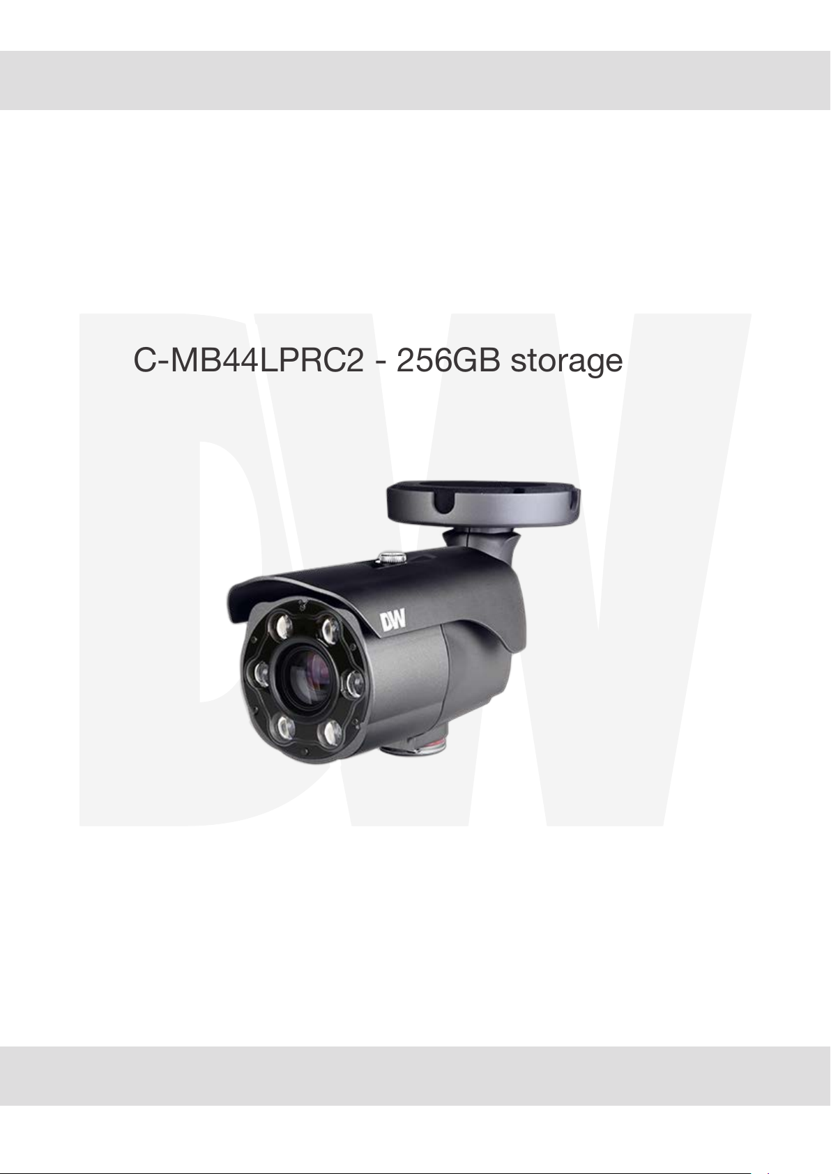
MEGApix® CaaS
TM
4MP
LPR IP camera
DWC-MB44LPRC6 - 64GB storage
DWC-MB44LPRC1 - 128GB storage
DWC-MB44LPRC2 - 256GB storage
User’s Manual
Before installing and using the camera, please read this manual carefully.
Be sure to keep it handy for future reference.
Ver. 02/20
Page 2
Safety Information
CAUTION
RISK OF ELECTRIC SHOCK.
DO NOT OPEN.
CAUTION
:
TO REDUCE THE RISK OF ELECTRIC SHOCK, DO NOT REMOVE COVER (OR BACK) NO USER SERVICEABLE
PARTS INSIDE. REFER SERVICING TO QUALIFIED SERVICE PERSONNEL.
Warning Precaution
This symbol indicates that dangerous voltage
consisting a risk of electric shock is present within
this unit.
WARNING
To prevent damage which may result in fire or electric shoc
hazard, do not expose this appliance to rain or moisture.
WARNING
1.
Be sure to use only the standard adapter that is specified i
the specification sheet. Using any other adapter could caus
fire, electrical shock, or damage to the product
2.
Incorrectly connecting the power supply or replacing battery
may cause explosion, fire, electric shock, or damage to th
product.
3.
Do not connect multiple cameras to a single adapter.
Exceeding the capacity may cause excessive heat generation
or fire
4.
Securely plug the power cord into the power receptacle.
Insecure connection may cause fire
5.
When installing the camera, fasten it securely and firmly
A falling camera may cause personal injury.
6.
Do not place conductive objects (e.g. screw drivers, coins,
metal items, etc.) or containers filled with water on top o
the camera. Doing so may cause personal injury due to fire
electric shock, or falling objects.
7.
Do not install the unit in humid, dusty, or sooty locations.
Doing so may cause fire or electric shock
8.
If any unusual smells or smoke come from the unit, stop
using the product. Immediately disconnect the power sorce
and contact the service center. Continued use in such a
condition may cause fire or electric shock
9.
If this product fails to operate normally, contact the nearest
service center. Never disassemble or modify this product in
any way.
10.
When cleaning, do not spray water directly onto parts of the
product. Doing so may cause fire or electric shock
Precaution
Operating
Handling
Installation and Storage
exceeding the allowed range.
This exclamation point symbol is intended to alert the
user to the presence of important operating and
maintenance (servicing) instructions in the literature
accompanying the appliance.
• Before using, make sure power supply and all other parts are
properly connected.
• While operating, if any abnormal condition or malfunction
is observed, stop using the camera immediately and contact
your dealer.
• Do not disassemble or tamper with parts inside the camera.
• Do not drop the camera or subject it to shock or vibration as
this can damage the camera.
• Clean the clear dome cover with extra care. Scratches and
dust can ruin the quality of the camera image.
• Do not install the camera in areas of extreme temperature,
• Avoid installing in humid or dusty environments.
• Avoid installing in places where radiation is present.
• Avoid installing in places where there are strong magnetic
fields and electric signals.
• A
void installing in places where the camera would be subject
to strong vibrations.
• Never expose the camera to rain or water.
Page 3
Important Safety Instructions
1. Read these instructions. - All safety and operating instructions should be read before installation or operation.
2. Keep these instructions. - The safety, operating and use instructions should be retained for future reference.
3. Heed all warnings. - All warnings on the product and in the operating instructions should be adhered to.
4. Follow all instructions. - All operating and use instructions should be followed.
5. Do not use this device near water. - For example: near a bath tub, wash bowl, kitchen sink, laundry tub, in a wet
basement; near a swimming pool; etc.
6. Clean only with dry cloth. - Unplug this product from the wall outlet before cleaning. Do not use liquid cleaners.
7. Do not
block any ventilation openings. Install in accordance with the manufacturer’s instructions. - Slots and
openings in the cabinet are provided for ventilation, to ensure reliable operation of the product, and to protect it
from over-heating. The openings should never be blocked by placing the product on bed, sofa, rug or other similar
surfaces. This product should not be placed in a built-in installation such as a bookcase or rack unless proper
ventilation is provided and the manufacturer’s instructions have been adhere to.
8. Do not install near any heat sources such as radiators, heat registers, or other apparatus (including amplifiers)
that produce heat.
9. Do not defeat the safety purpose of the polarized or grounding-type plug. A polarized plug has two blades with
one wider than the other. A grounding type plug has two blades and a third grounding prong. The wide blade
or the third prong are provided for your safety. If the provided plug does not fit into your outlet, consult an
electrician for replacement.
10. Protect the power cord from being walked on or pinched particularly at plugs, convenience receptacles, and
the point where they exit from the apparatus.
11. Only use attachments/accessories specified by the manufacturer.
12. Use only with cart, stand, tripod, bracket, or table specified by the manufacturer,
or sold with the apparatus. When a cart is used, use caution when moving the cart/apparatus
combination to avoid injury from tip-over.
13. Unplug the apparatus during lightning storms or when unused for long periods of time.
14. Refer all servicing to qualified service personnel. Servicing is required when the apparatus has been damaged
in any way, such as power supply cord or plug is damaged, liquid has been spilled or objects have fallen into the
apparatus, the apparatus has been exposed to rain or moisture, does not operate normally, or has been
dropped.
Disposal of Old Appliances
1. When this crossed-out wheel bin symbol is attached to a product it means the product is covered by the
European Directive 2002/96/EC.
2. All electrical and electronic products should be disposed of separately form the municipal waste stream
stream in accordance to laws designated by the government or the local authorities.
3. The correct disposal of your old appliance will help prevent potential negative consequences for the
environment and human health.
4. For more detailed information about disposal of your old appliance, please contact your city office,
waste disposal service or the shop where you purchased the product.
This equipment has been tested and found to comply with the limits for a Class A digital device, pursuant to part 15 of the FCC Rules.
These limits are designed to provide reasonable protection against harmful interference when the equipment is operated in a commercial environment.
This equipment generates, uses, and can radiate radio frequency energy and, if not installed and used in accordance with the instruction manual, may cause
harmful interference to radio communications. Operation of this equipment in a residential area is likely to cause harmful interference in which case the user
will be required to correct the interferenece at his own expense.
Page 4

Index
INTRODUCTION
0
INSTALLTION
0
1
1
NETWORK SETUP
WEB VIEWER SCREEN
2 Basic Screen
Important Safety Information
'FBUVSFT
Product & Accessories
Part Name
Installation
Cabling
Inserting / Removing an SD Memory Card
%8*1'JOEFS
Quick Start of Network Connection
DDNS Registration
Guide to Network Environment
Setup Case (A~D)
Port Forwarding
Starting IP Camera
SETUP
APPENDIX
7
SPECIFICATION
Video & Audio Setup
Camera Setup
Network Setup
Trigger Action Setup
Events Setup
Record Setup
Security Setup
System Setup
Current TCP/IP Settings
Changing IP Address and Subnet mask
4QFDJGJDBUJPOT
FAQ
DimensionT
8BSSBOUZ
-JNJUTBOE&YDMVTJPOT
2
Page 5
Introduction -
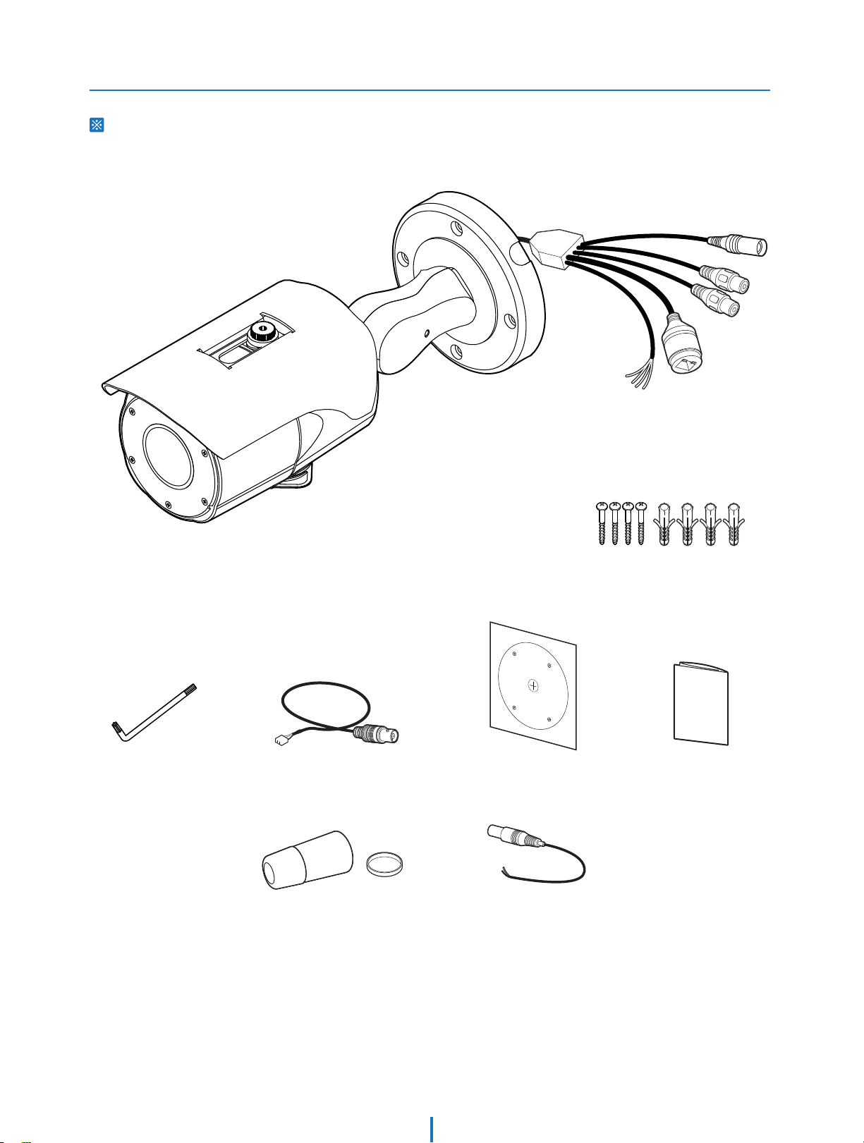
Product & Accessories
Please check if all the camera and accessories are included in the package.
Cables
Torx Wrench
Camera
Screw & Plastic Anchor-4pcs
Test Video Cable Quick ManualTemplate Sheet
Waterproof cap & Gasket DC Plug Cable
Page 6
Introduction -
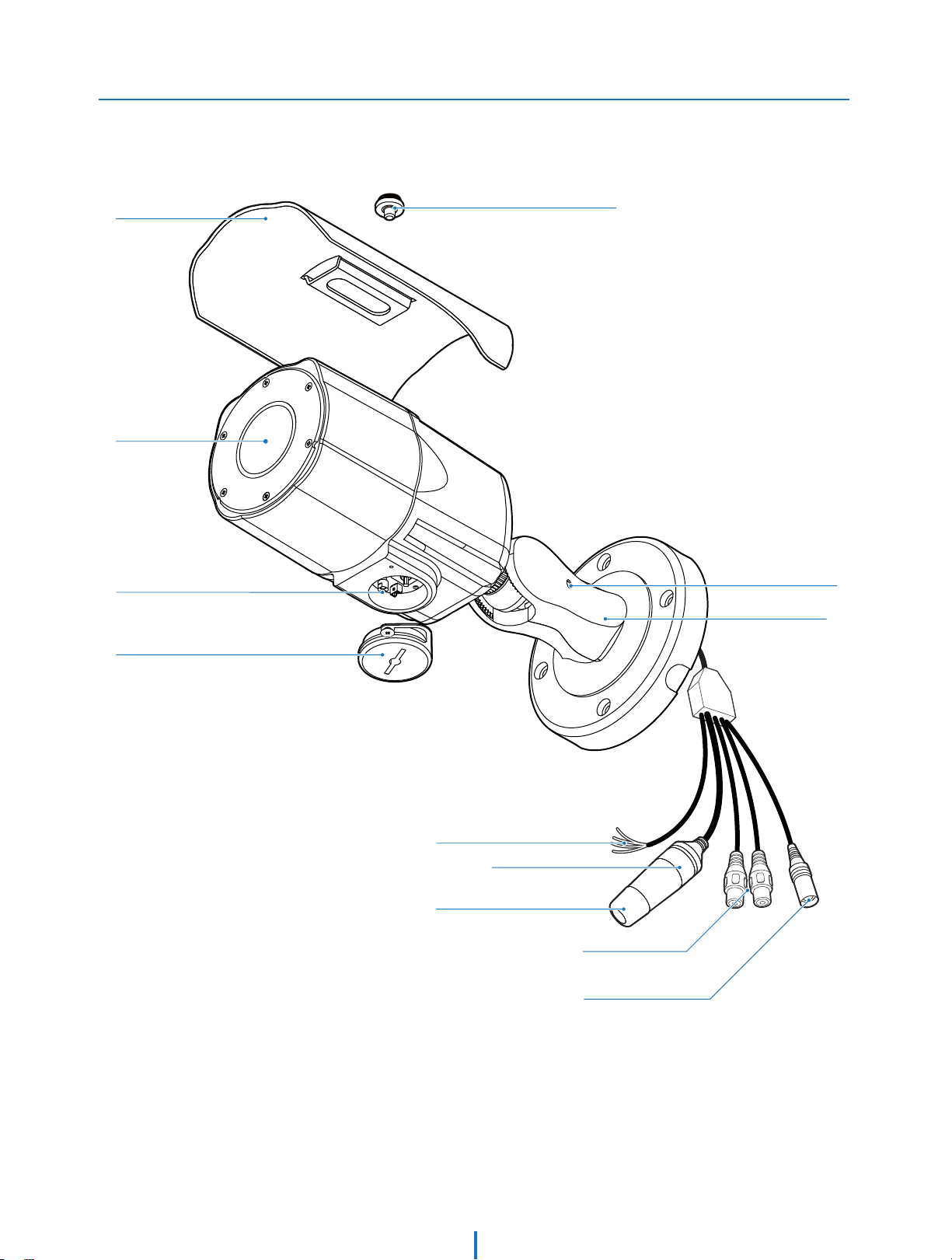
Part Name
Sunshield
Lens
Control Board
Con Cap
Sunshield Adjusting Screws
Pan/Tilt Stoper Screw
Bracket
Alarm In/Out
RJ-45 Connector
Waterproof cap
Audio In/Out
DC Power Jack
Page 7
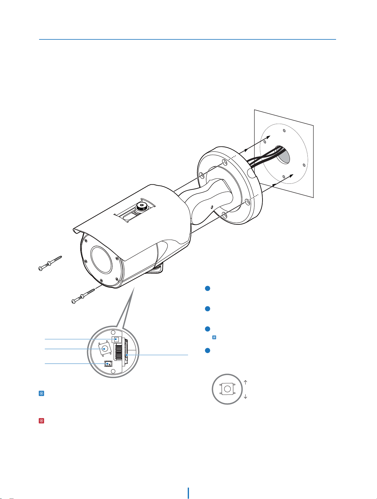
Installation -
Installation
Before installing your camera, you have to read the following cautions.
1. You have to check whether the location can bear ve times of the weight of your camera.
2. Don’t let the cable to be caught in improper place or the electric line cover to be damaged. Otherwise
it may cause a breakdown or re.
3. When installing your camera, don’t allow any person to approach the installation site. If you have any
valuable things under the place, move them away.
Reset
T-W Jog Button
SD Card Slot
Test Video Output
Reset to the Factory Default
Press the reset button for 5 seconds to return the setup
to the factory default.
Warning
If you press the ‘Reset’ button, you will lose all setting
data. If needed, please, make a note for further
installation.
1
Using the Template sheet, make the cabling hole on
the wall/ceiling.
2
Connect the network cable, power cable respectively.
See the section ‘Installation - Cabling’ for details.
3
Fix the camera on the wall/ceiling by screw provided.
Loosen the Pan/Tilt stoper screw a litte before xing the camera.
4
By using the test video cable, check the screen during
installation. You can adjust the zoom ratio using the
T-W jog button.
WIDE
TELE
Zoom Out
Zoom In
Page 8
Installation -
Installation
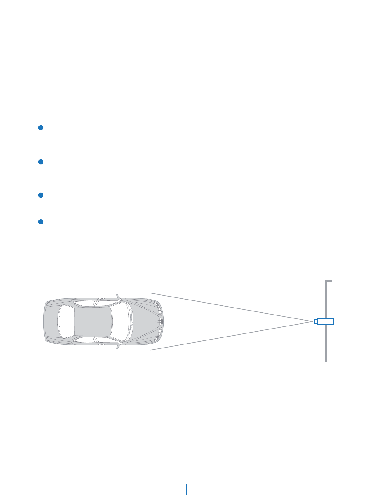
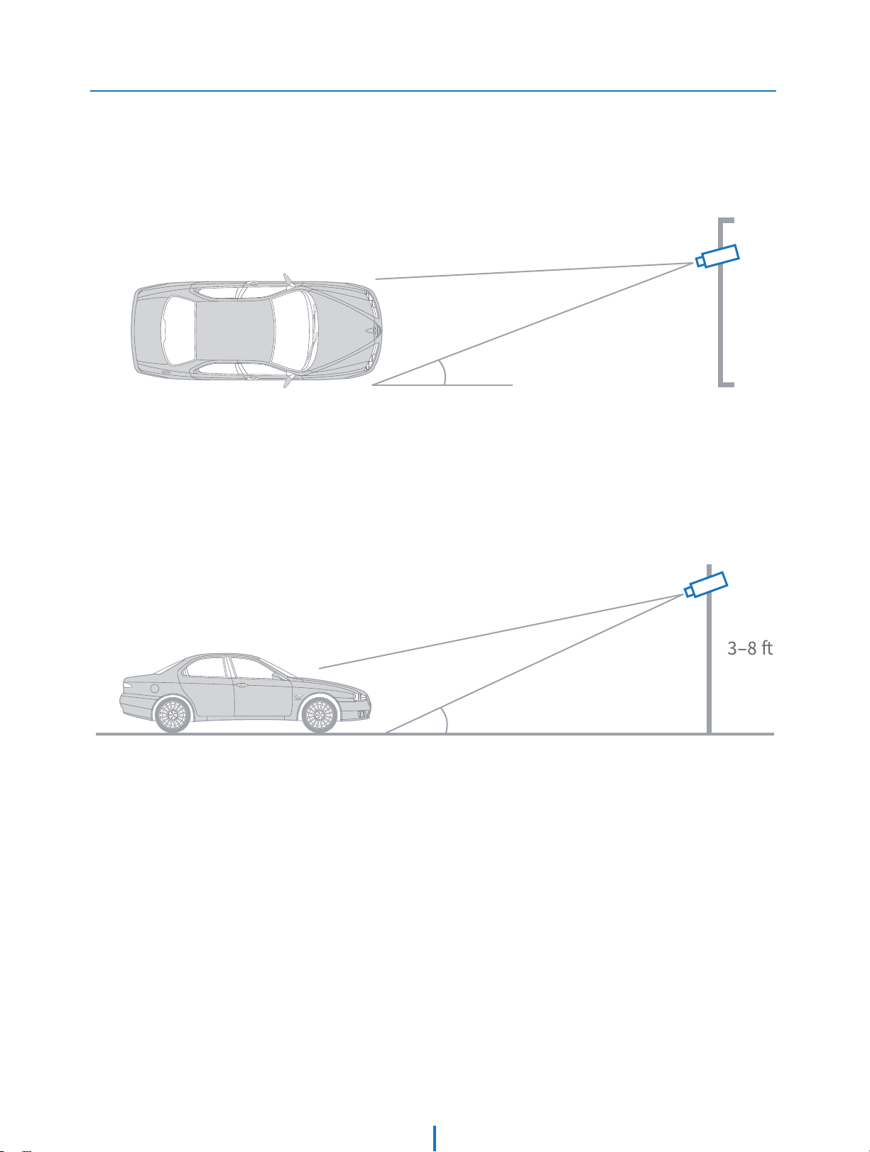
An LPR camera is designed to read a license plate only. When a license plate passes by the camera, the
reective lm on the plate will be reected back to the camera which gives youthe good clear shot of
the plate. You will ONLY capture an image of the plate.
US license plates need to be at least 216 pixels wide. This translates roughly into an image no wider than
5-6 feet assuming 1440p standard denition video.
1
The horizontal angle between the camera and plate should be
within 20° degrees. This means that if your camera is 10 feet
away from the plate, the plate cannot be more than 3 feet to the
right or left of the camera.
The vertical angle between the camera and plate is within 30°
2
degrees. This means that if your camera is 10 feet away from the
plate and the plate is 3 feet o the ground, the camera cannot
be mounted more than 8 feet high.
3
Attempting to position the security camera at odd angles or
exceeding the distance capabilities will result in a poor shot of
the plate.
4
The DVR’s recording fps should be at the highest to assure best
capture quality.
THE CAMERA SHOULD BE MOUNTED AT AN ANGLE NO GREATER THAN 30 DEGREES
10
Page 9
Installation -
Installation
CAMERA ANGLE NO GREATER THAN 20 DEGREES FOR SIDE MOUNT INSTALLATIONS
cGYW
cGZW
THE CAMERA SHOULD BE MOUNTED AT AN ANGLE NO GREATER THAN 30 DEGREES
Page 10
Installation -
Cabling
Two Options
Use a PoE-enabled switch to connect data and power through a single cable and begin viewing and recording images instantly.
A non-PoE switch will require an adaptor for power transmission.
1. 6TJOHB1P&4XJUDIPS1P&*OKFDUPS
The Camera is PoE-compliant, allowing transmission of
power and data via a single Ethernet cable.
PoE eliminates the need for the dierent cables used to
power, record, or control the camera. Follow the illustration
below to connect the camera to a PoE-enabled switch using
an Ethernet cable.
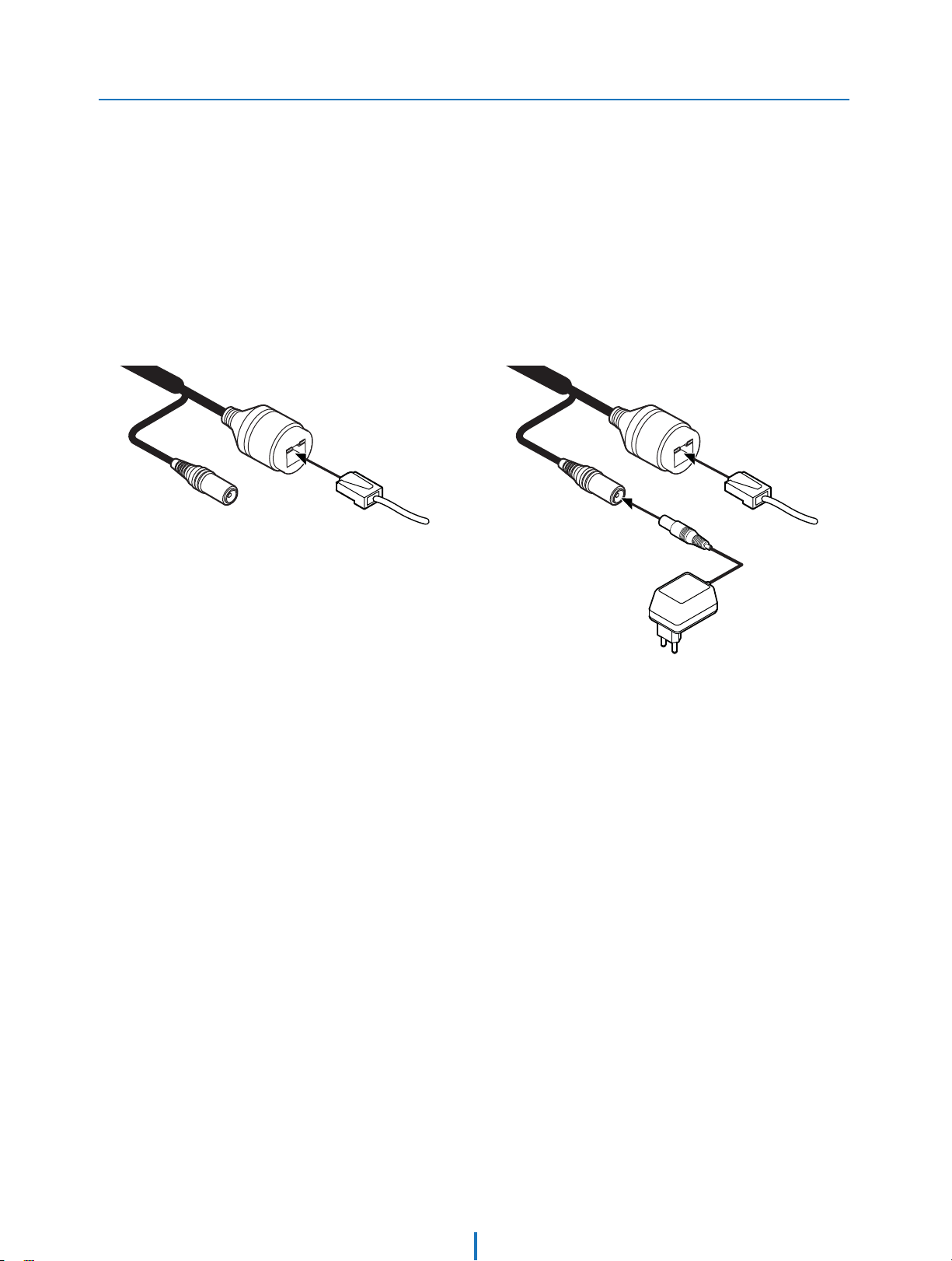
2. /PUVTJOH1P&4XJUDIPS1P&*OKFDUPS
If a PoE-enabled switch is not used, use a power adaptor
for power transmission and non-PoE switch for data
transmission.
Follow the illustrations below to connect the camera
without a PoE-enabled Switch.
Ethernet cableEthernet cable
Power
Page 11
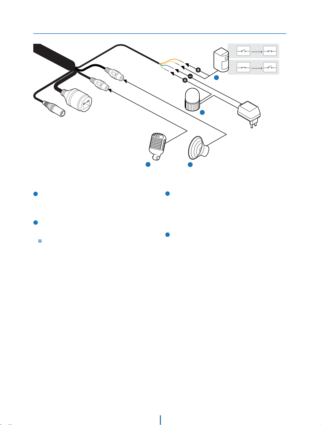
Installation -
Cabling
3
Alarm Out
4
Alarm In
N.O
N.C
,Q
&20
,Q
&20
DI : Orange
DI COM : Yellow
DO1(N.O.) : Green
DO1 COM : Blue
Activation
Activation
,Q
&20
,Q
&20
1
Audio In8IJUF+BDL
Connect the ‘Audio In’ cable of the camera to the device
like microphone.
2
Audio Out3FE+BDL
Connec
t the ‘Audio Out’ cable of the camera to device like
speaker.
Audio Out supports only RTSP Back channel function. It plans to make it
available on the web later.
1
Audio In
8)*5&+BDL
3
4
2
Audio Out
3&%+BDL
Alarm Out
It connects to the alarm lights, siren or lamps and the sensor
types are normal open and normal close.
Cable of the alarm output device should connect to DO1
(N.O.) and DO1 COM of the cable slot.
Alarm In
Cable of the sensor/alarm input device should connect to
orange and yellow line of the Alam cable.
Page 12
Installation -
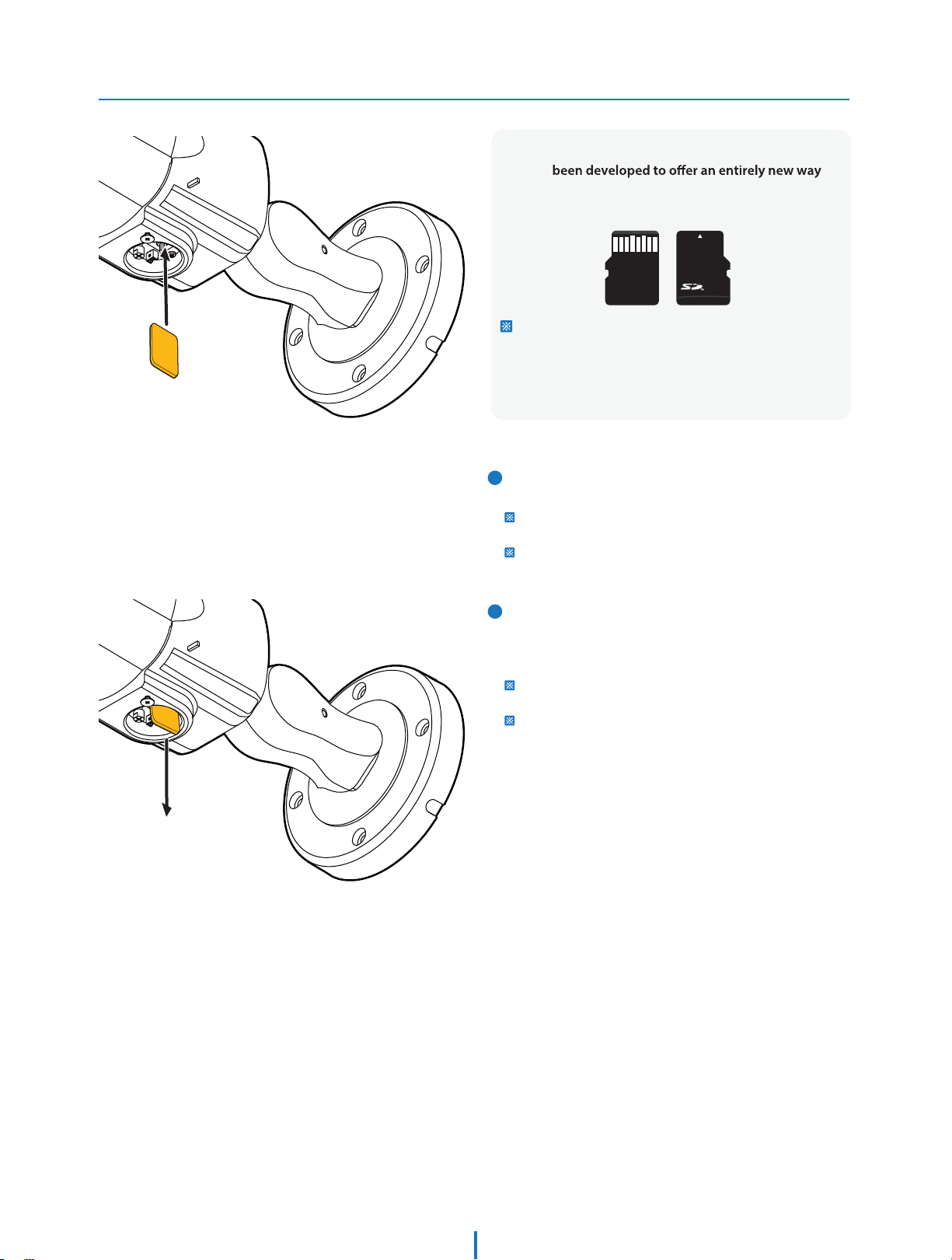
Inserting/Removing SD Memory Card
The memory card is an external data storage device
that has
to record and share video, audio, and text data using
digital devices.
Micro
Recommended SD Card Specication (Not Included)
- Type: Micro SD (SD/SDHC/SDXC)
- Manufacturer: Transcend, Kingston, Toshiba, SanDisk
- Capacity: 4GB~GB
- Class: over UHS-I U3 Class 10
1
Inserting an SD Memory Card
Insert the SD card in the arrow direction.
Don’t insert the SD memory card while it’s upside down by force.
Otherwise, it may damage the SD memory card.
Use the tweezers when inserting or picking out the SD card.
2
Removing an SD Memory Card
Removing an SD Memory Card Gently press down on the
exposed end of the memory card as shown in the diagram
to eject the memory card from the slot.
Pressing too hard on the SD memory card can cause the card to
shoot out uncontrollably from the slot when released.
If you have saved data in the SD memory card, removing the SD
memory card prior to setting record to OFF will cause damage to
the data stored in the card.
Page 13
Network setup -
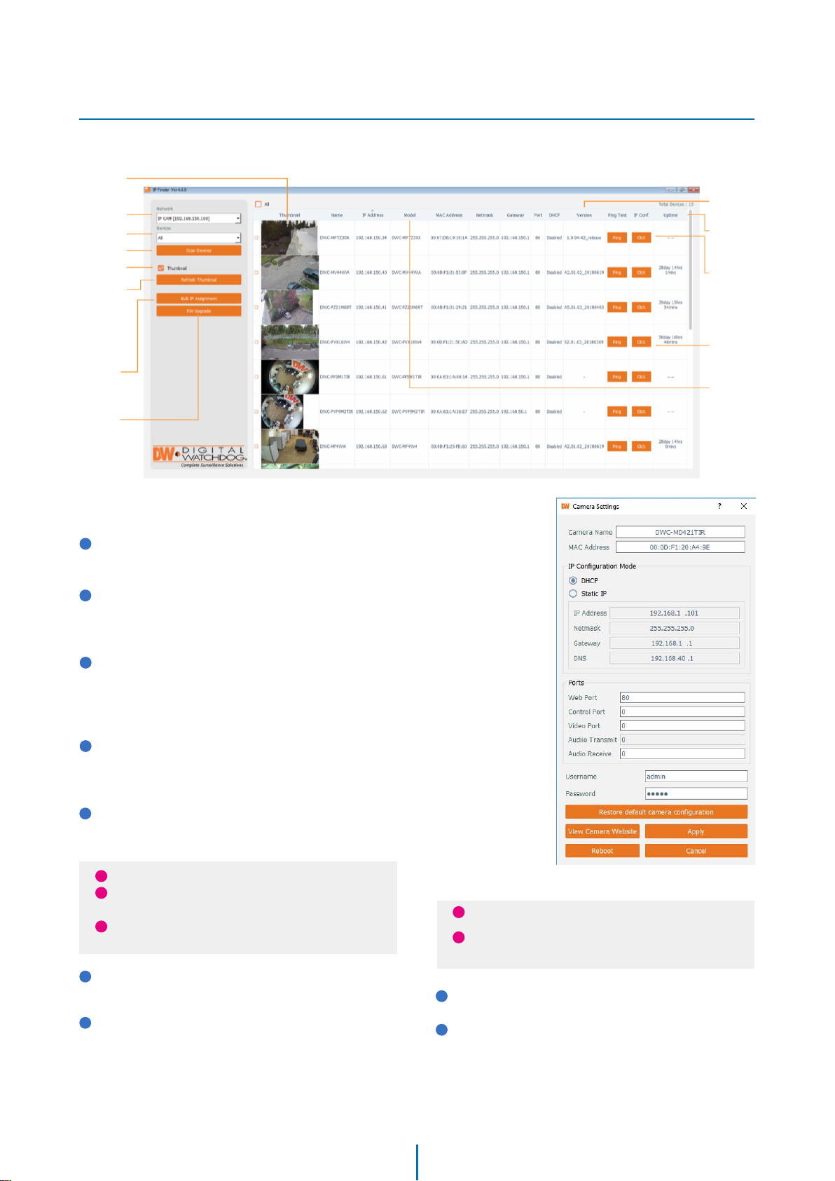
DW IP Finder
Thumbnail view
Select network to scan
Filter device type to scan
Scan devices
Show/hide
thumbnail view
Refresh thumbnail view
TM
Firmware version
Camera's uptime
Open device
configuration
settings
Bulk IP assignment
Firmware upgrade
1
Go to : http://www.digital-watchdog.com and search for
‘IP Finder’ on the quick search bar at the top of the page.
2
The latest IP Finder software will appear in the search
results. Click on the link to download the file to your
computer.
3
The software will scan your network for all supported
cameras and display the results in the tabel. Allow up to
5 seconds for the IP Installer to find the camera on the
network.
4
You can press the ‘Refresh List’ to search the network
again, or filter the search results by entering a value in
the filter box.
Device's
information
5
Check the box next to ‘Display Camera Thumbnail’ to view
a JPEG image of the camera’s view next to the camera
name on supported models.
i
The default network type of camera is DHCP mode.
i
If you have a DHCP server, it will automatically set the
Camera IP.
i
Contact your network administrator for more
information.
6 To save the changes made to the camera's settings, input
ID and PW of the camera for authentication.
7 If the camera needs to be rebooted after the settings were
changed, press the 'Reboot' button. The camera will power
cycle and will appear back in the search results once the
reboot is complete.
Default ID / PW : admin / admin
i
i For security purposes, it is highly recommended to
change your password after initial setup.
8 Click 'Save' to save changed values.
9 To update the camera's firmware from the DW IP Finder
click on the firmware tab, upload the firmware file and
select the camera to update. You can update multiple
cameras at the same time.
16
TM
,
Page 14
Network Setup -
Quick Start of Network Connection
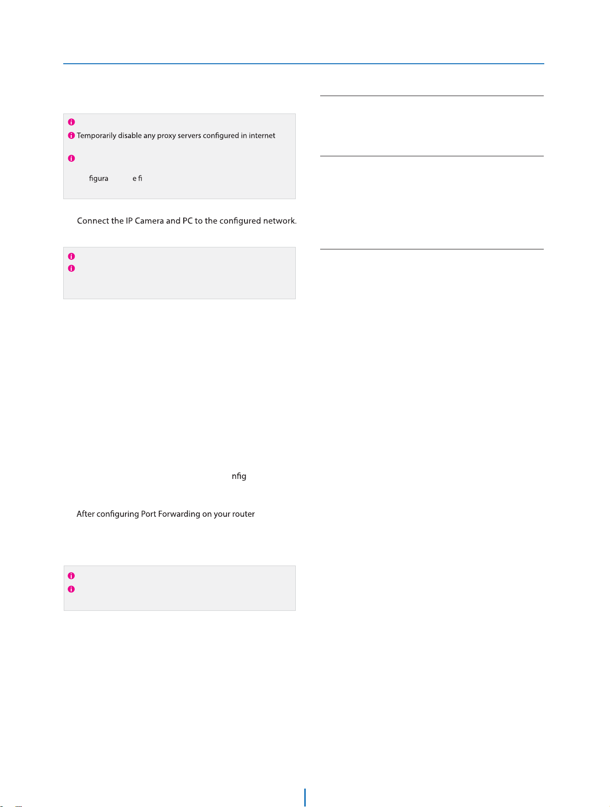
Access your IP Camera via the Internet :
Please follow the steps below to complete
the initial setup of the network function.
Please do not power on the IP Camera until instructed.
Explorer.
If connecting the IP Camera directly to a modem, power down
and reset the modem. Leave the modem powered down until
con tions ar nalized with the IP Camera and the IP Camera
has been correctly connected to the modem.
1.
Open the IP Installer on a PC, then search for the IP camera.
2.
If you have a DHCP server, it will automatically set the Camera IP.
If you do not have a DHCP server, Camera IP is set to 192.168.1.80
after one minute. In this case, PC IP must be changed to the IP to
be able to access the 192.168.1.80.
If multiple numbers of camera are connected it should be
3.
distinguished by the mac address of the Camera.
11.
If you use a static IP address assigned by your ISP
1) Open Internet Explorer.
2) Type the IP of the IP Camera.
3) If you use a router, type the routers’ static IP and the web port
number of the IP Camera.
If you have a dynamic address provided by your ISP
1) Open Internet Explorer and visit the DDNS website.
2) Register the IP Camera.
3) Reboot the IP Camera.
4) Give the DDNS server 10 minutes to locate your IP Camera’s
IP information.
5) Click the refresh button in the Internet Explore.
6) After your camera is connected, select your camera.
Click the Camera IP, and connect to the WEB PAGE.
4.
Default ID/Password to access IP Camera are both the
5.
word: admin.
Familiarize yourself with the Viewer Interface Screen.6.
please install VLC to display live video.7.
The IP setting can be set to ‘STATIC’ at IP Installer or web
8.
viewer followed by Setup -> Network -> TCP / IP.
If the IP Camera is connected to a network which utilizes a
9.
router, you must have Port Forwarding co ured on your
personal router to forward all ports to the IP address you
have assigned the IP Camera.
10.
(if necessary), you may access your IP Camera on your local
network by opening Internet Explorer and specifying the IP
address and Web Port that you have assigned to the IP
Camera.
Example: http://192.168.0.200:8888
If you leave your Web Port set to 80, you don’t need to specify
the port in the Address Bar to access to your IP Camera.
Page 15

Network Setup -
DDNS Registration
If you have DYNAMIC IP service from your
Internet Service Provider (ISP), you can’t tell
the current IP address of the IP Camera.
To solve this problem, you have to register to
our DDNS service.
A
dynamic addressing. If so, register your IP
Video Server on our DDNS website before you
c re, setup, or install the IP Camera.
Even though your IP is not dynamic, you will
just remember ‘hostname.dyndns.com/gate1’
instead of complicated series of numbers like
http://201.23.4.76:8078.
For more details, contact our Support Center.
t, you have to check if you are using
To use a public DDNS called ‘dyndns’ or ‘no-ip’, refer to the detail
information on how to use the service.
(Visit the web site : http://www.dyndns.com or
http://www.no-ip.com)
Page 16

Network Setup -
Guide to Network Environment
Please congure the IP Camera at the
installation site. You must determine your
network scenario in order to congure the IP
Camera with the proper TCP/IP settings.
This tutorial will guide you through the
process. Before actually conguring the IP
Camera, determine settings to be applied.
Record those settings to be used to congure
your IP Camera for reference.
When conguring your IP Camera, treat the
IP Camera as another PC on your network.
You will assign it several addresses and other
TCP/IP properties to match your current
network.
This step-by-step tutorial will teach what IP
addresses and network congurations should
be assigned based on the network scenario.
1.
Before you begin, locate any information and settings
received from your Internet Service Provider (ISP). You may
need to refer to these IP addresses at a later time during the
conguration.
Current TCP/IP Settings
IP Address
Subnet Mask
Default Gateway
Primary DNS Server
Secondary DNS Server (Option)
Static Dynamic
5. The following descriptions are several basic network
scenarios. Determine which scenario describes your network.
If your network does not match one of the scenarios below
and you are unsure how to setup your IP Camera, contact
your network administrator and then call our Support Center.
You cannot control the rectangular gray areas and only the ISP
has access to the devices.
If you were not given any IP addresses or the ISP was responsible
for the setup and installation of your Internet connection, go to
step 2.
If you are not using a router on your network, your ‘Current TCP/IP
Settings’ (from the previous section) and ‘Assigned IP Addresses
from My ISP’ will be exactly the same.
2.
You must determine whether the IP address is STATIC or
DYNAMIC. At this moment, you are only concerned about the
ISP. Did they provide you with a STATIC or DYNAMIC address?
If you are unsure, contact your ISP.
3.
Congure your IP Camera’s TCP/IP settings for network
connectivity by selecting Setup from the main interface and
selecting TCP/IP located on the left of the Setup screen.
4.
If prompted for ID and Password, use ‘admin’ for both entries.
The default web port number is 80. If port 80 is blocked by
the ISP, a value between 1025 ~ 60000 should be used. If TCP
port 80 is blocked, consult the ISP
Page 17
Network Setup -
Setup Case A, B
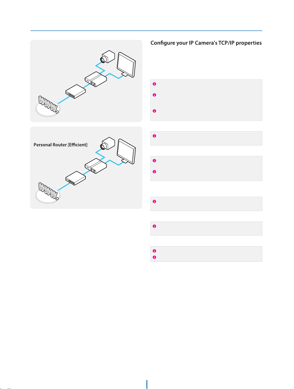
Case A:
Dynamic IP +
Personal Router [Most SOHO]
Internet
Phone Line
or CATV
Cable/xDSL Modem
(ISP Provided)
Case B:
Static(Fixed) IP +
Public Line
Internet
Gateway or Router
at ISP
Camera
Personal Router
W/Intergrated Switch
Camera
Personal Router
W/Intergrated Switch
as follows :
Network Type :1.
Internet Address :2.
PC
You need to assign an IP address to the IP Camera just as you do
with PC.
The IP address you assign must be unique to your network and
match your network as well. For information on how to choose
a unique IP and match your network, read the FAQ.
The IP address you assign must be a private IP. For information
on how to choose a private IP please, read the FAQ.
Subnet Mask :3.
You must use the same subnet mask as the one you noted under
‘Current TCP/IP Settings’.
Default Gateway :4.
This IP address must be the IP address of your router.
PC
(private or LAN side)
Use the same Default Gateway you noted under ‘Current TCP/IP
Settings’.
Preferred DNS Server :5.
If you did not receive any IP addresses from your ISP, contact
the ISP and acquire the IP address of their DNS server.
STATIC (even though you have Dynamic IP from
your ISP, use STATIC on the IP Camera)
A private IP address such as
192.168.0.200 (Example)
255.255.255.0 (Example)
192.168.0.1 (Example)
Use the 1st DNS Server from ‘Assigned IP
Address from My ISP’.
DDNS Server :6.
This is the same site you will register later to accommodate
dynamic IP from your ISP.
Do not use the default port 80 as this number must be changed.
You may select any number between 1025 ~ 60000.
Use the DDNS server.
8888Web Port :7.
Page 18
Network Setup -
Setup Case C, D
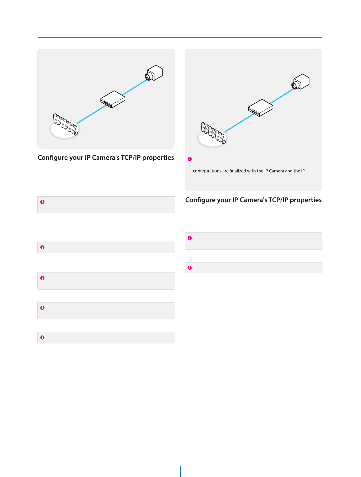
Case C:
Static(Fixed) IP [Dedicated line directly
to the IP Camera]
Camera
Phone Line
or CATV
Internet
Cable/xDSL Modem
(ISP Provided)
as follows :
STATICNetwork Type :1.
Internet Address :2.
You need to assign an IP address to the IP Camera just as you do
with PC.
Subnet Mask :3.
Default Gateway :4.
Use the assigned default gateway from your ISP
A static IP address received from your ISP such
as 24.107.88.125 (Example)
Subnet mask assigned from your ISP such as
255.255.255.240 (Example)
24.107.88.113 (Example)
Case D:
Dynamic IP + DSL/Cable Modem [Connected
directly to the IP Camera]
Public Line
Internet
To connect the IP Camera directly to a modem, power down
and reset the modem. Leave the modem powered down until
Camera has been connected correctly to the modem. Then
power on the modem, followed by the IP Camera.
Gateway or
Router at ISP
as follows :
DYNAMICNetwork Type :1.
Use the DDNS serverDDNS Server :2.
This is the same site you will register later to accommodate
dynamic IP from your ISP.
Camera
Preferred DNS Server :5.
If you have not received any IP addresses from your ISP, contact
them to acquire the IP address of their DNS server.
DDNS Server :6.
This is the same site you will register later to utilize our DDNS
service.
80Web Port :7.
You may select any number between 1025 ~ 60000.
Use the 1st DNS Server from ‘Assigned IP
Address from My ISP’
Use the DDNS server
80Web Port :3.
You may select any number between 1025 ~ 60000.
Page 19
Network Setup -
Port Forwarding
After entering the correct TCP/IP settings, you
are ready for ‘Port Forwarding’(Cases A, B).
Please record the TCP/IP settings of your IP Camera for future
1.
reference. You may need this information to access your IP
IP Camera TCP/IP Settings
IP Address
Subnet Mask
Default Gateway
Preferred DNS Server
DDNS Server
Web Port
After clicking ‘Apply’, the system will prompt for a reboot.
2.
Please allow the system 50 seconds to reboot and accept the
changes. After 50 seconds, close the con
The view will display ‘Trying to Reconnect’. If the ACTIVE light
, the IP Camera has rebooted. After the system
reboots completely, remove the power supply from the
unit and close Internet Explorer.
Return your PC/Laptop TCP/IP properties to their original
3.
settings.
Before installing the IP Camera, you must use ‘Port
4.
Forwarding’ on your personal router (Cases A, B).
You will need to forward 1 ports:
t Web Port
All the ports will be forwarded to the IP address you
assigned to the IP Camera.
In the example above, you would forward:
t
ration screen.
For information on how to use ‘Port Forwarding’, please read
Appendix C.
Page 20
Network Setup -
Starting IP Camera
After forwarding correctly the Web Port,
through your router (if applicable), install the
IP Camera in a proper location.
1.
Locate the serial number located on the label attached to the
bottom of the IP Camera, you will need this for DDNS
registration.
2.
Connect the IP Camera to your router or cable/DSL modem
(per your network scenario) via a Cat5/5e UTP Ethernet
network cable.
3.
Supply power to the IP Camera.
4.
After 1 minute, the IP Camera will operate.
5.
(if necessary), access your IP Camera on your local network
by opening Internet Explorer and specifying the IP address
and Web Port assigned to the IP Camera.
Examples: http://192.168.0.200:8888 or http://24.106.88.123
If you left your Web Port set to 80, do not need to specify the
port in the Address Bar to access the IP Camera.
Access your IP Camera via the Internet :6.
If you use Case B, C
1) Open Internet Explorer.
2) Type the IP of the IP Camera.
If you use Case A, D
1) Open Internet Explorer.
2) Visit the DDNS website.
3) Register the IP Camera.
4) Give the DDNS server 10 minutes (MAX) to locate your IP
Camera’s IP information. You may reboot the server to send an
immediate request to our DDNS server.
5) After your camera is connected, select your camera.
The di ence between B and C is that B needs to set the port
forwarding.
Since the type of DDNS
the related service site.
s from the service type, refer to
Page 21
Web Viewer Screen -
Basic Screen
1
2
3
4
5
Web viewer is optimized with explorer10 or above version
and Firefox.
If VLC is not installed or VLC plugin is not supported (Chrome),
to Live Viewer menu, and then if HTML5(MJPEG) is selected on
Live Viewer menu, then you can check the video.
1
Live video display. This is the region for live video stream
from the camera.
2
Setup popup button. Click it to open the Setup page to
setup details of IP camera like Video, Network, Events,
System and etc. See the section ‘Setup’ .
3
When the image goes unsmoothly because of bad network
connection, it stored image during setup time and shows
the image on the live view screen.
User will see the delayed images as much as setup time.
5
Below “Menu”is supported in accordance with models.
PTZ Control
This camera model supports the zoom and focus.
Preset
Does not support.
Speaker Control
Enable/Disable Audio stream received
from the camera and Volume control of the speaker in the
Computer.
Alarm Input
If the alarm is triggered, the color of corresponding input number
will be changed to bright red from dark gray.
Relay Out
Using these Checkbox, you can read status of Relay Out and also
set or reset it manually.
6
7
4
Channel Select button. Select a stream produced from the
camera between Stream 1 ~ 3 to display it in the live view
screen.
Refer the ‘ Setup -> Video & Audio -> Video ’ to setup the Video
Stream.
6
Motion
It shows the Motion event status.
Event Alert Icon ( ) appears if ‘Motion Detection’ is activated.
7
Camera Time
Display the camera time.
Page 22
Setup - Video & Audio Setup
Video Configuration
1
2
1
Detail Page
When you selects an item from the menu, you can set the
details for the selected item.
2
Setup Constitution
Video&Audio
[ VIDEO, OSD, ROI, AUDIO, PRIVACY MASK ]
Camera
[ IMAGE ADJUSTMENT, EXPOSURE, IMAGE, VIDEO ]
Network
[ STATUS, NETWORK SETTING, AUTO IP, ONVIF, UPNP,
DDNS, FTP, SMTP, SNMP, RTSP INFORMATION ]
Trigger Action
[ ACTION RULES, IMAGE TRANSFER, RELAY OUT ]
Events
[ EVENT RULES, MOTION, TEMPERATURE, ALARM INPUT ]
Record
[ MANAGEMENT, RECORD LIST, STORAGE ]
Security
[ IP ADDRESS FILTER, RTSP AUTHENTICATION, IEEE 802.1x,
HTTPS, CERTIFICATES, SERVICE ]
System
[ INFORMATION, FIRMWARE UPDATE, DATE&TIME , DST ,
USER MANAGEMENT, LOG, FACTORY RESET, RESTART ]
Page 23

Setup - Video & Audio Setup
Video Configuration
1
2
3
4
5
1
Live Video Channel Setup
The video can be congured to variety settings with a
combination of codec and resolution.
The camera performance has to be considered when setting
multiple channels. This eects on the performance of the
camera.
2
Codec
Choose the video codec. According to the selected codec,
the subcategories can be changed automatically.
When MJPEG codec is selected, it will be able to set whether
to use the relevant channel for image transfer.
3
Description
Input the additional description about the selected channel.
Max. 30 alphabets are allowed(Including space). For the
description, English Alphabets, numbers and special
characters ( - _ @ . ) can be used.
4
Resolution
Select the video resolution.
Available resolution can be depends on the codec setup between
the channels.
PAL
2560 x 1440
2304 x 1296
1920 x 1080
1280 x 720
800 x 600
640 x 480
704 x 576
704 x 480
352 x 288
352 x 240
4M
3M
1080p/i
720p/i
SVGA
VGA
4CIF
CIF
5
Frame Rate
NTSC
2560 x 1440
2304 x 1296
1920 x 1080
1280 x 720
800 x 600
640 x 480
704 x 576
704 x 480
352 x 288
352 x 240
<Resolution of Video Format>
Select the maximum Frame Rate.
Available Frame Rate can be dierent although same codecs
were set up.
Page 24
Setup - Video & Audio Setup
Video Configuration
6
7
8
6
GOP(Group of Pictures) Size
Set up the number of frames (P-frame) which contain only
changed information based on basic frame (I-frame).
Regarding videos with lots of movement, if you set GOP size
bigger, only the number of P-frames is bigger. As a result,
video resolution will be low but ‘File size’ and ‘Bit-rate can
be decreased.
GOP(Group of Pictures) Size is..
I-frame and P-frame can be created for MPEG4 and H.264 video
compression. I-frame(=key-frame) means the whole image data
for one specic scene of video. P-frame is image data which has
been changed information compared to I-frame GOP is made up
of one I-frame and corresponding several P-frames. To improve
video quality, set the number of P-frames smaller and to decrease
image size, set the number of P-frames bigger.
7
Prole
The prole denes the subset of bit stream features in an
H.264 stream, including color reproduction and additional
video compression.
Baseline
A simple prole with a low compression ratio.
Main
An intermediate prole with a medium compression ratio.
High
A complex prole with a high compression ratio.
8
Smart Bitrate Control
O
Does not use the Smart Bitrate Control.
CVBR (Framerate priority)
This Mode is for cameras which do not want absolute any
frame drop, but still want to get lower bitrate. It has
limitation when the Target bitrate is set to be very low,
but actual motion is big or scene is very noisy.
CVBR (Quality priority)
When the Target bitrate is set to very low, and motion is big,
then LBR will try to drop frames, and make the nal fps to
be lower, so that it can save its and make the output frames
to have better quality.
CBR
This Mode is a CBR alike mode which is close to traditional
security IPCAM, and it's not designed for LBR, It's provided
as an option in LBR library just to help comparison.
Page 25

Setup - Video & Audio Setup
Video Configuration
9
10
11
12
13
9
Bitrate Mode
Select the bit rate control scheme of video compression
from CBR (Constant Bit Rate) or VBR (Variable Bit Rate).
CBR
To guarantee the designated constant bit rate, the quality
of video are controlled in this mode. Therefore, the quality
of video is likely to be varying when network trac is
changing.
VBR
To guarantee the designated quality, the bit rate of video
stream is changed in this mode. Therefore, the frame rate
of video is likely to be varying when network trac is
changing.
This category won't be appear if you select the codec.
10
Target Bitrate
If Bitrate Control is set to be CBR, you can set the Target
Bitrate.
11
Extension Option
OFF
Does not use the extension option.
SVC-T On
Scalable video coding is a type of video encoding algorithm
that can be applied to streaming , so that , they could be
transmitted over lossy, low bandwidth networks eectively.
12
Quality
For VBR control mode, The Target Quality of video can be
setup.
Click ‘Apply’ to make above setting effective.
13
Page 26

Setup - Video & Audio Setup
OSD Configuration
3
1
2
Date / Time
1
Display the current time.
2
User Text
Output the TEXT entered by the user.
Support a maximum of 30 characters.
3
Click ‘Apply’ to make above setting effective.
Page 27

Setup - Video & Audio Setup
Region of Interest Conguration
4
1
2
3
Region of interest function gives much more eciency picture
quality for indicated area to improve picture qualities of
movement scene at the same bandwidth.
1
Stream
Select the Stream.
Currently it supports only Channel1.
2
Activation
The Region of interest can be enable or disable.
3
Quality
Set the quality of the set area.
4
Click ‘Save’ to save the current settings.
Click 'Cancel' to return to the previous setting.
Page 28

Setup - Video & Audio Setup
Audio Conguration
4
1
2
3
1
Codec
Select the Audio Codec.
Currently it supports only codec G.711.
Volume
2
Select the Audio Volume from 0 to 10.
3
Sample Rate
Select the Audio Sample Rate.
Currently it supports only 8000 Hz.
4
Click ‘Apply’ to make above setting eective.
Page 29

Setup - Video & Audio Setup
Privacy Mask Conguration
3
1
2
Use this function to mask areas that you want to hide on
screen to protect privacy.
Activation
1
The Privacy mask function can be enable or disable.
2
Area
Select the Area1 ~ Area4 and Set the privacy area.
3
Click ‘Save’ to save the current settings.
Click 'Cancel' to return to the previous setting.
Click ‘Clear Area' to delete the selected Area1~Area4.
Page 30

Setup - Camera Setup
Camera Image Adjustment
1
2
3
4
5
1
Sharpness
Using this control, sharpness of image can be adjusted
to meet your preference.
2
Brightness
Using this control, brightness of image can be adjusted
to meet your preference.
3
Contrast
Using this control, contrast of image can be adjusted to
meet your preference.
4
Saturation
Using this control, Saturation of image can be adjusted
to meet your preference.
5
Click ‘Save’ to save the current settings.
Click 'Cancel' to return to the previous setting.
Click 'Default' to settings to the factory defaults.
Page 31

Setup - Camera Setup
Camera Exposure Settings
1
2
3
4
5
6
7
1
Auto Exposure
Automatic exposure(AE) automatically sets the aperture or
shutter speed, based on the external lighting conditions
for the photo.
2
Exposure Level
If this value is increases, the image becomes brighter.
3
AE Metering
AE metering mode refers to the way in which a camera
determines the exposure.
4
Shutter Speed
If this speed is faster, the moving object can be photographed
without the ghost eect. However, picture can be dark if
there is no sucient lighting.
5
Slow Shutter Level
Slow shutter Level lets you adjust the amount of light striking
the sensor, and essentially determines when the video sensor
sends out its batch of data for processing.
6
Gain Limit
The smaller number makes the daker image.
7
Click ‘Save’ to save the current settings.
Click 'Cancel' to return to the previous setting.
Click 'Default' to settings to the factory defaults.
Page 32

Setup - Camera Setup
Camera Image Enhancement
4
1
2
3
1
3D Noise Reduction
3DNR function enables to suppress noise and retain
good video quality in low light conditions.
Mirror
2
Reverse the video from side to side.
3
Flip
Reverse the video from up to down.
4
Click ‘Save’ to save the current settings.
Click 'Cancel' to return to the previous setting.
Click 'Default' to settings to the factory defaults.
Page 33

Setup - Camera Setup
Video Enhancement
2
1
1
Flicker
2
Click ‘Save’ to save the current settings.
Click 'Cancel' to return to the previous setting.
Click 'Default' to settings to the factory defaults.
Page 34

Setup - Network Setup
Network Status
This menu will show you all the information of Network setting in the camera. However, you cannot change those here.
Page 35

Setup - Network Setup
Network Settings
10
1
2
3
4
5
6
7
8
9
1
Network Type
Dene network IP address type from the Static Mode for the
xed IP or the Dynamic Mode by the dynamic IP address.
If you select the Static Mode, you must ll out IP Address,
Subnet Mask, Gateway, DNS Server and all ports.
If you select the Dynamic Mode, the IP address will be
allocated automatically by DHCP equipment. If you click
the Apply button to update changes, the system will be
re-booted. In this case, you have to reconnect the camera
using new IP address.
2
IP Address
Dene the IP address. The address is consisted of four
numbers separated by dots and the range of each number
is from 0 to 255.
3
Subnet Mask
Dene the Subnet Mask. Format is same as the IP address.
4
Default Gateway
Default the Gateway IP Address. Format is same as the IP
address.
5
Preferred DNS Server
Dene the DNS server IP address. Format is same as the
IP address.
6
Alternate DNS Server
Dene the Secondary DNS server IP address. Format is
same as the IP address.
7
HTTP Port
The HTTP port can be set to 80 which default or in between
1025 to 60000.
8
HTTPS Port
The HTTPS port can be set to 443 which default or in betwe
-en1025 to 60000.
9
RTSP Port
The RTSP port can be set to 554 which default or in between
1025 to 60000.
10
Click ‘Apply’ to make above setting eective.
If the network type is dynamic, the IP address is changed in
below cases. Therefore, the IP address needs to be searched
again, and the camera needs to be reconnected in these
cases.
- When the camera power is on / o.
- After Firmware update, Default set and reboot.
Page 36

Setup - Network Setup
Auto IP Settings
3
1
2
1
General Setting
Auto IP Settings function can be enable or disable.
2
Auto IP Settings Information
It displays the unique id or Auto IP address.
3
Click ‘Apply’ to make above setting effective.
Page 37

Setup - Network Setup
ONVIF Settings
3
1
2
1
Authentication
None: Allows to access without ONVIF authentication.
WS-Uesrtoken: Allows to access with WS-User
Token of ONVIF authentication.
WS-Usertoken +Digest: Allows to access with WS-User
Token and Digest of ONVIF authentication.
2
Discovery Mode
The discorvery function can be enable or disable.
3
Click ‘Apply’ to make above setting effective.
Page 38

Setup - Network Setup
UPNP Settings
3
1
2
1
General Setting
UPNP function can be enable or disable.
2
Friendly Name
Define the friendly name.
3
Click ‘Apply’ to make above setting effective.
Page 39

Setup - Network Setup
DDNS Settings
3
1
2
1
DDNS Disable
If it is selected, DDNS service does not work.
2
Public DDNS
To use public DDNS service, select a site address listed in the
list. After lling out the Host Name of the site, the setup is
completed by entering User Name and Password registered
in that DDNS site.
DDNS Provider Site Address
DynDNS
No-IP
If you setup DDNS properly, the IP address of your camera will be
updated automatically whenever IP address is changed or system
is rebooted.
If IP updating to DDNS site is failed, camera will keep retrying in
1min. interval.
3
Click ‘Apply’ to make above setting eective.
www.dyndns.com
www.no-ip.com
Page 40

Setup - Network Setup
FTP Settings
7
1
2
3
4
5
6
To transfer / save the image to the relevant sites through FTP,
then FTP needs to be setup.
1
General Setting
FTP function can be enable or disable.
2
FTP Server Address
Dene FTP Server IP Address. If IP Address form is incorrect,
a Message box will be shown to try again.
3
FTP Upload Path
Dene a path in FTP server to store video. For the path name,
English Alphabets, numbers and special characters ( / ~ !@ $
^ ( ) _ - { } [ ] ; , ) can be used.
4
FTP Port
Dene the FTP Server Port. If Port is not appropriate, it is
impossible to access to FTP Server.
5
User ID
Dene User ID to access to the FTP Server. Fill out the correct
User ID registered in the FTP Server.
6
Password
Dene Password to access to the FTP Server. Fill out the
correct Password registered in the FTP Server.
7
Click ‘Apply’ to make above setting eective.
Refer the above screen image for the example.
Page 41

Setup - Network Setup
SMTP Settings
1
2
3
4
5
6
7
8
9
10
11
To send / save the image to the relevant sites by Email, SMTP
needs to be setup.
1
General Setting
SMTP function can be enable or disable.
2
Mode
Select Security mode of SMTP from Plain or SSL / TLS. After
checking account setup of your SMTP Server, you may
select one.
3
SMTP Server Address
Dene the SMTP Server Address. If the IP Address form is
incorrect, a Message box will be shown to try again.
4
Port
Dene the Port used in the Plain or SSL / TLS security mode
in the above.
5
User ID
Dene the User ID to access to SMTP Server. Fill out the
correct User ID registered in the SMTP Server.
6
Password
Dene the Password to access to SMTP Server. Fill out the
correct Password registered in the SMTP Server.
7
E-Mail Sender
Dene the e-mail address of E-Mail Sender. It will be
displayed as the sender when the camera sends an E-mail.
8
E-Mail Receiver
Dene the e-mail address of E-Mail Receiver. It will be
displayed as the Receiver when the camera sends an E-mail.
9
Title
Dene the title of the E-Mail when the camera sends an
E-mail.
The title of the Email is limited to 40 characters including
the spaces.
10
Message
Dene the contents of E-Mail when camera sends an E-mail.
The message of the Email is limited to 40 characters including
the spaces.
11
Click ‘Apply’ to make above setting eective.
Page 42

Setup - Network Setup
SNMP Settings
1
2
3
4
5
6
7
8
9
10
11
1
SNMPv1/SNMPv2
Select the SNMPv1/SNMPv2 option and type the names of
Read community and Write community.
SNMP trap can be used to check periodically for operational
thresholds or failures that are dened in the MIB.
2
SNMP Trap
SNMP trap can be enable or disable.
SNMPv3 contains cryptographic security, a higher security
level, which allows you to set the Authentication password
and the Encryption password.
3
Mode
Select the either Read or Read/Write mode.
4
Activation
It can be enable or disable selected mode.
5
Read/Write name
Dene Read name and Write name.
7
Authentication Algorithm
Select MD5 or SHA as the authentication method.
8
Authentication Password
The Authentication Password is an encryption for
authentication and they are at least 8 digits and up
to 30 digits allowed.
9
Private-Key Algorithm
Select DES or AES as the encryption algorithm.
10
Private-Key Password
Information protection password is a private encryp
-tion and they are at least 8 digits and up to 30 digits
allowed.
11
Click ‘Apply’ to make above setting eective.
6
Security Level
Select one of no auth, no priv/auth , no priv/auth, priv
Page 43

Setup - Network Setup
RTSP Information
1
2
3
4
5
1
Target Stream
Select the channel you want to set.
2
Time out
Set the RTSP time out.
The session is disconnected after the specied time out.
3
RTP Multicast
Check RTP Multicast On/O. To activate RTP Multicast,
1. Click “On” button
2. Enter accessible RTP Multicast IP, port for video stream
control, RTP packet TTL
3. Click “Apply” button.
It is possible to set each RTP Multicast for CH1~3.
4
Click ‘Apply’ to make above setting eective.
Click this button when completed setup each channels.
5
It shows RTSP Connection information.
Page 44

Setup - Trigger Action Setup
Action Rules Configuration
1
2
1
Action rules List
It indicates the custom action rule information added to
Action rules list.
2
Click ‘Add’ to add custom action rules.
Click ‘Modify' to modify selected item from the action rules list.
Click 'Delete' to delete selected item from the action rules list.
Page 45

Setup - Trigger Action Setup
Action Rules Add / Modify
3
1
2
1
Name
Define name of action rules.
2
Action1 ~ Aciton5
Select the action to take If the event occurs.
3
Click ‘Save’ to save the current settings.
Click 'Cancel' to return to the previous menu.
Page 46

Setup - Trigger Action Setup
Image Transfer Configuration
2
1
1
Pre / Post Alarm Image
Image Transfer due to event is configured by setting Image
transfer rate and Pre / Post alarm duration.
Descriptions
Number
of Image
Pre-alarm
Duration
Post-alarm
Duration
2
Click ‘Apply’ to make above setting eective.
Dene Number of image transferred per second.
Define duration of image transfer before an event.
Define duration of image transfer after an event.
Page 47

Setup - Trigger Action Setup
Relayout Conguration
5
1
2
3
4
1
Relay Output
Select the Relay output.
The number of relay outputs depends on the camera model.
2
Mode
Select the monostable / bistable for relay mode.
3
Idle State
Select whether the contact is normally opened or is closed.
4
Duration
Relay out is operated during the setting time.
If bistable mode is selected, this funtion is activation.
5
Page 48

Setup - Events Setup
Event Rules Configuration
2
1
Event Rules List
1
It indicates the custom Event Rule information added to
Event Rules list.
2
Click ‘Add’ to add custom event rules.
Click ‘Modify' to modify selected item from the event rules list.
Click 'Delete' to delete selected item from the event rules list.
Page 49

Setup - Events Setup
Event Rules Configuration
4
1
2
3
Name
1
Define the Event rule name.
Event
2
Select the event among motion detection, schedule.
Click 'Cancel' to return to the previous setting.
You need a event one more.
Rules
3
Select the action rule defined in the Trigger Action-Action
rule menu.
4
Click ‘Save’ to save the current settings.
Click 'Cancel' to return to the previous setting.
Page 50

Setup - Events Setup
Motion Detection Conguration
1
2
3
4
5
1
Motion Detection
It shows the Motion event status.
Event Alert Icon( ) appears if ‘Motion Detection’ is activated.
2
Area
Set the motion detected area.
You can set up to four areas.
Activation
3
Enable or Disable motion detection function.
Sensitivity
4
High value is
selected, it will detect very small motion while it becomes
relatively insensitive when Low value is selected.
5
Click ‘Save’ to save the current settings.
Click 'Cancel' to return to the previous setting.
Page 51

Setup - Event Setup
Temperature
4
1
2
3
1
Mode
Select the either Fahrenheit and Celsius.
2
Threshold
Dene the temperature at which the event trigger is
occurred.
3
Temperature
It indicates the current temperature of the IP camera.
4
Click ‘Apply’ to make above setting eective.
Page 52

Setup - Events Setup
Alarm Congurtaion
2
1
Input Device Setup
1
Select input device type from OFF / N.O. / N.C.
Operation
OFF
NO
NC
2
Ignore this Input sensor.
The contact is normally open and closed
when activated.
The contact is normally closed and open
when activated.
Page 53

Setup - Edge Setup
DW Spectrum® Edge
Version - Displays the version of DW Spectrum® edge (media server) installed in the camera.
Status - Displays
status of the server is marked as 'alive'.
Select a new version of DW Spectrum® edge (media server) file to update and upload.
Update with selected file. If you select file, it will be activated.
DW Spectrum® edge (media server) start / stop
- Start : Start the DW Spectrum® edge (media server) installed in the camera.
- Stop : Close the DW Spectrum® edge (media server) installed in the camera.
DW Spectrum® edge (media server) restart / remove
- Restart : Restart the DW Spectrum® edge (media server) installed in the camera.
- Remove : Delete the DW Spectrum® edge (media server) installed from the camera.
Before DW Spectrum® edge (media server) install.
the status of the DW Spectrum® edge (media server) installed in the camera. Wait until the
55
Page 54

Setup - Edge Setup
Storage Configuration
Display the SD card information mounted from device.
When you select the item in Storage list, You can set the functions related to the SD card.
56
Page 55

Setup - Edge Setup
Storage Configuration
Storage Size - Total capacity of SD card and the remainder of it are displayed.
Unmount - Remove the SD card from the device. UNMOUNT cannot be done when EDGE (Media server) is running.
Format - Delete the all contents that stored in SD card. FORMAT cannot be done when EDGE (Media server) is running.
57
Page 56

Setup - Security Setup
IP Address Filter Configuration
3
6
1
2
4
5
IP Address Filter
1
IP filter function can be enable or disable.
2
IP Filter Type
Select the recording IP filter type.
3
Click ‘Apply’ to make above setting eective.
4
Filter IP Address
Display the filterd IP address.
5
IP Address
Define the IP address you want to apply the IP filter.
6
Click ‘Add’ to add the ip address to the list.
Click ‘Remove’ to remove the ip address selected in the list.
Click ‘Remove All’ to remove all ip in the list.
58
Page 57

Setup - Security Setup
RTSP Authentication Configuration
2
1
1
RTSP Authentication
RTSP Authentication can be enable or disable.
2
Click ‘Apply’ to make above setting effective.
59
Page 58

Setup - Security Setup
IEEE 802.1X Configuration
9
1
2
3
4
5
6
7
8
The featureis needed when connecting the camera to the
network protected bythe IEEE 802.1X.
IEEE 802.1x
1
The IEEE 802.1x feature can be enable or disable.
2
Protocol
MD5: It provides one-way password-based network
authentication of the client.
PEAP: It is similar to TTLS in that it does not require a certifi
-cate on the client side.
TTLS/MD5: It does not require a certificate on the client side.
TLS: It relies on client-side and server-side certificates to
perform authentication.
3
EAPOL Version
Select the EAPOL Version.
4
ID
Type the ID to identify the client in the IEEE 802.1X authen
-tication server.
5
Password
Type the Password to identify the client in the IEEE 802.1X
authentication server.
6
Verify
Verify Password.
CA Certificate
7
Select the CA certificate required for TLS, TTLS, and
PEAP authentication.
8
Certificate
Select the client certificate required for TLS authen
-tication
9
Click ‘Apply’ to make above setting effective.
0
Page 59

Setup - Security Setup
HTTPS Configuration
1
2
3
HTTPS encrypts session data over SSL or TLS protocols
instead of using plain text in socket communications.
Certificate
1
Select an installed certificate.
If you can not select a certicate, please install the certicate
from the Security->Certicates menu.
2
HTTPS connection Policy
Select one of “HTTP”, “HTTPS”, “HTTP and HTTPS”
depending on the connected user authority.
3
Click ‘Apply’ to make above setting effective.
When HTTPS mode is chosen, input https://<IP Address> to
connect to the camera.
1
Page 60

Setup - Security Setup
Certificates Configuration
1
2
5
6
Server/Client Certificates
1
It show the installed certificates.
2
Create Self-Signed Certificate
A self-signed SSL certificate is an identity certificate signed
by its own creator. but they are considered to be less trust
-worthy.
3
Properties
Shows information about the selected certificate.
4
Delete
Delete the selected certificate.
5
Create Certificate signing request
This is the encoded data that contains the necessary infor
-mation for issuing the certificate.
they must be lled in when creating the CSR (Certicate Signing
Request).
3
7
9
6
Install Certificate
Install Certification
7
CA Certificate
It show the installed CA certificates.
8
Install CA Certificate
Install Certification, see the detail page.
9
Properties
Shows information about the selected certificate.
10
Delete
Delete the selected CA certificate.
4
10
2
Page 61

Setup - Security Setup
Certificates Configuration
1
2
5
9
Detail for Install Certification.
Certificate From Signing Request
1
Select to install signed certificate returned from the CA.
2
Certificate And Private Key
Select to install Certificate And Private Key to install a certi
-ficate and private key.
Use Seperate Key: Too install certificate uploading Certifi
-cate and Private Key file.
PKCS#12” : “PKCS#12” is cryptography standard.
if you want to install using PKCS#12,
must enter the password.
3
Certificate Name
Enter a unique name to identify certificate.
4
Select File
Choose certification file.
3
4
6
7
8
10
6
Cancel
Cancel install certificate and then back to certificates
configuration.
Detail for Install CA Certification.
7
Certificate Name
Enter a unique name to identify CA certificate.
8
Select File
Choose CA certification file
9
OK
Request installing CA certificate.
10
Cancel
Cancel install CA certificate and then back to certi
-ficates configuration.
5
OK
Request installing certificate.
3
Page 62

Setup - Security Setup
Service Configuration
2
1
Telnet
1
The Telnet function can be enable or disable.
2
Click ‘Apply’ to make above setting eective.
4
Page 63

Setup - System Setup
System Information
2
1
System Capability information.
Device Name
1
You can define the device name.
6
Click ‘Apply’ to make above setting eective.
5
Page 64

Setup - System Setup
Firmware Update
1
2
3
1
Version Information
It shows the current Firmware Version in the system.
2
Web Update
Select the Firmwar le in your computer by clicking
[Select le] button.
3
Start F / W Update
Click this button to start update. Progress of uploading will
be displayed using Progress Bar. If you assign the wrong le
name, an error massage will be shown.
Warning:
1. Do not turn o the power of camera during the Firmware
update. Otherwise, the system can be stuck to be unstable.
If updating is nished, the system will be rebooted
automatically.
2. Please make sure to check the ‘Notice’ shown on screen.
If rmware update is completed, the camera will reboot
automatically and ‘Setup window’ will be closed.
6
Page 65

Setup - System Setup
Firmware Update
4
5
6
7
8
9
4
FTP Server Address
Dene FTP Server IP Address. If IP Address form is incorrect,
a Message box will be shown to try again.
5
FTP Port
Dene the FTP Server Port. If Port is not appropriate, it is
impossible to access to FTP Server.
6
User ID
Dene User ID to access to the FTP Server. Fill out the correct
User ID registered in the FTP Server.
7
Password
Dene Password to access to the FTP Server. Fill out the
correct Password registered in the FTP Server.
8
FTP Upload Path
Dene a path in FTP server to store video. For the path name,
English Alphabets, numbers and special characters
( / ~ ! @ $ ^ ( ) _ - { } [ ] ; , ) can be used.
9
Click ‘Save’ to make above setting eective.
SAVE Save FTP information
CANCEL Click 'Cancel' to return to the previous setting.
CHECK
Check the F/W le and if the le exists, ‘F/W Update’
button will appear and click it to update for F/W.
67
Page 66

Setup - System Setup
Date & Time Settinges
1
2
3
4
5
6
1
TimeZone Setup
Choose TimeZone for camera. It will be activated after
clicking ‘Apply’ button.
Prior to setting below ‘New Camera Date & Time’, set correct
Timezone rst.
2
Current Date & Time
Shows the current date and time setting in the Camera.
3
Synchronize with my computer
Set the date / time using those of PC currently connected.
4
Setup manually
Set the date / time by typing manually.
5
Synchronize with time server(NTP)
Choose time server available to connect to current camera.
Date & Time will be updated automatically every hour
when connected.
6
Click ‘Apply’ to make above setting eective.
68
Page 67

Setup - System Setup
DST Settings
3
1
2
Daylight Saving Time (DST) is the practice of setting the clocks
forward one hour from standard time during the summer
months, and back again in the fall, in order to make better
use of natural daylight.
1
General Setting
DST function can be enable or disable.
2
Date&Time Settings
Set the Start time and end time that the DST apply.
3
Click ‘Apply’ to make above setting eective.
69
Page 68

Setup - System Setup
Users Management
1
2 3 4
1
Users
List all the user accounts for authentication.
2
Add
Register a new user
ID Enter a new user ID except Admin since it exists.
Password
Verify
User
Authority
The ID and Password are limited to 10 characters.
Click ‘Apply’ to make above setting eective.
Click 'Cancel' to return to the previous menu.
Enter the user Password.
Enter the user Password again for verication.
Select Operator or Viewer.
Viewer : Only monitoring is allowed.
Operator : Most of the functions are allowed except ‘Setup’.
Administrator : All functions are allowed.
3
Modify
Modify the information of the user accounts registered.
For admin account, only Password function can be modied.
4
Delete
Delete the selected user account. Admin account cannot
be deleted.
0
Page 69

Setup - System Setup
System Log
2
1
3
1
Filter
Select a date, sort or type of log to lter the log.
2
Click the 'Refresh' button to refresh the log list.
Click 'Filter' to view the ltered log.
3
System Log List
The ltered log is displayed.
1
Page 70

Setup - System Setup
Factory Reset
1
2
1
Reset to the factory defaults
Return the setup to the factory default.
All
Reset all Settings to the factory defaults.
Except Network Settings
Except Network related settings , reset all others to the
factory default.
2
Click ‘Apply’ to make above setting eective.
2
Page 71

Setup - System Setup
Restart
3
Page 72

Appendix
A : Current TCP/IP Settings
If your IP settings are obtained automatically, you could use the MS-DOS prompt (or Command Prompt) to determine your IP address.
For information on how to do this, please read the FAQ.
Windows 7 Users
Start
Control Panel
Network and
sharing center
Manage network
connections
Properties
Select either
Internet Protocol
Ver.4 (TCP/IPv4)
or Internet Protocol
Ver.6 (TCP/IPv4)
2. Windows 10 Users1.
Start
Settings
Network & Internet
Click on Change
adapter options in
Ethernet
Select the Ethernet,
Right click and
choose Properties
Select either
Internet Protocol
Ver.4 (TCP/IPv4)
or Internet Protocol
Ver.6 (TCP/IPv4)
Click Properties
Under the ‘General’ tab of the
TCP/IP Properties you will see
your IP address information.
Click Properties
Under the ‘General’ tab of the
TCP/IP Properties you will see
your IP address information.
4
Page 73

Appendix -
B : Changing IP address and subnet mask
Windows 7 Users
Start
Control Panel
Network and
sharing center
Manage network
connections
Properties
Select either
Internet Protocol
Ver.4 (TCP/IPv4)
or Internet Protocol
Ver.6 (TCP/IPv4)
2. Windows 10 Users1.
Start
Settings
Network & Internet
Click on Change
adapter options in
Ethernet
Select the Ethernet,
Right click and
choose Properties
Select either
Internet Protocol
Ver.4 (TCP/IPv4)
or Internet Protocol
Ver.6 (TCP/IPv4)
Click Properties
Select ‘Use the following IP
address’
Click Properties
Select ‘Use the following IP
address’
5
Page 74

Appendix -
FAQ
1. My POWER light is not on?
Power is not being supplied to the unit. Please use the power
supply shipped with the unit and verify that a power source
is active from the attached power outlet used to connect the
adapter. You can test this by plugging in an y other electrical
device and verify its operation. After using the power supply
shipped with the product, checking the power source, and
reinserting the power connector into the IP Camera, please
call our Support Center. The power supply may be defective.
My ACTIVE light is not flashing?
2.
Verify the power supply to the unit. Power off the unit and
back on again, wait 1 minute, if the ACTIVE light still does
not begin to flash, you will have to set the unit to its factory
default (THIS WILL DELETE ANY CONFIGURATION AND SET
THE UNIT TO THE FACTORY DEFAULTS). Power on the unit
and inert the end of a paper clip into the small recessed
opening on the back of the unit. Use the clip to press the
button located within that opening.
3. My LINK light is not flashing or solid?
Verify the cable connection. 99% of the time the cable’s
connection to the unit is causing this problem. Try using a
different network cable or crossover cable (for PC connection
only). Try reinserting the cable, if this still doesn’t solve the
problem call our Support Center.
4. I can access the video server on my LAN, but not from the
Internet.
Verify that your router (if applicable) has port forwarding
properly configured. If accessing from our DDNS service,
verify correct serial number. Firewall issues may prevent user
access.
5. How do I open an MS-DOS or Command Prompt?
Start > (All) Programs > Accessories > Command Prompt
6. How do I find out my IP address information if my settings
were automatically detected?
1) Open a Command Prompt
2) At the prompt type - “ipconfig / all” (without the quotes)
3) Near the end of the informati on supplied, should be your
current IP address, subnet mask, default gateway and DNS
servers
8. How do I “PING” an IP address?
1) Open an MS-DOS (or Command) prompt
2) At the prompt type - “ping xxx.xxx.xxx.xxx” (without the
quotes and replace the “x” s with an IP address)
3) Press Enter
9. I’m accessing my video server remotely over the Internet
and the video stream is choppy, is this normal?
Yes. The frames per second received remotely are
determined by your bandwidth capabilities both at your site
where the IP Camera is installed and your remote location.
The lower of the two sites will determine how fast your
video stream is received. It is recommended to have at least
a 256Kb/sec upstream connection from the site where the
IP Camera is installed. Lower speeds will operate properly,
but provide poor remote performance. The Faster the
Internet connection at both ends, the faster the video
stream.
10. How do I enable or check VL C on my browser
Internet Explorer
Open Internet Explorer > Tools on the menu bar > Internet
Options > Security Tab > Custom Level > Scroll down and
verify that you are prompted or have enabled plug-ins to be
downloaded and executed. > click OK > restart browser.
Chrome
Open Chrome > Chrome menu settings > Advanced settings >
Individual information - content settings > Run automatically
11. How do I reset the unit to factory defaults?
Refer to the previous functions page and find the reset button.
Power ON the unit and use a paper clip to push the reset button
within that opening. You should then see the ACTIVE light turn
off and after a few seconds the ACTIVE light will begin to flash,
signifying a successful reboot. If the ACTIVE light does not turn
off after depressing the reset button, please try holding the
button in for a few seconds and releasing. YOU WILL LOSE ALL
DATA THAT HAD BEEN ENTERED PREVIOUSLY AND THE IP CAM
-ERA WILL BE SET TO ITS FACTORY RESETS.
7. I can’t connect!!
In the case of a connection failure.
Modem Reboot > Modem Reboot Finished > Router Reboot
> Router Reboot Finished > IP Camera Reboot > IP Camera
Reboot Finish > Verify DDNS and IP Camera connection, if
applicable.
76
Page 75

Appendix -
FAQ
1.
My POWER light is not on?
Power is not being supplied to the unit. Please use the power
supply shipped with the unit and verify that a power source
is active from the attached power outlet used to connect the
adapter. You can test this by plugging in any other electrical
device and verify its operation. After using the power supply
shipped with the product, checking the power source, and
reinserting the power connector into the IP Camera, please
call our Support Center. The power supply may be defective.
2.
Verify the power supply to the unit. Pow unit and
back on again, wait 1 minute, if the ACTIVE light still does
not begin t ash, you will have to set the unit to its factory
default (THIS WILL DELETE ANY CONFIGURATION AND SET
THE UNIT TO THE FACTORY DEFAULTS). Power on the unit
and insert the end of a paper clip into the small recessed
opening on the back of the unit. Use the clip to press the
button located within that opening.
3.
Verify the cable connection. 99% of the time the cable’s
connection to the unit is causing this problem. Try using a
di
t network cable or crossover cable (for PC connection
only). Try reinserting the cable, if this still doesn’t solve the
problem call our Support Center.
4.
I can access the video server on my LAN, but not from the
Internet.
Verify that your router (if applicable) has port forwarding
ccessing from our DDNS service,
verify correct serial number. Firewall issues may prevent user
access.
5.
How do I open an MS-DOS or Command Prompt?
Start > (All) Programs > Accessories > Command Prompt
How d d out my IP address information if my settings
6.
were automatically detected?
1) Open a Command Prompt
3) Near the end of the information supplied, should be your
current IP address, subnet mask, default gateway and DNS
servers
8.
How do I “PING” an IP address?
1) Open an MS-DOS (or Command) prompt
2) At the prompt type - “ping xxx.xxx.xxx.xxx” (without the
quotes and replace the “x”s with an IP address)
3) Press Enter
9.
I’m accessing my video server remotely over the Internet
and the video stream is choppy, is this normal?
Yes. The frames per second received remotely are
determined by your bandwidth capabilities both at your site
where the IP Camera is installed and your remote location.
The lower of the two sites will determine how fast your
video stream is received. It is recommended to have at least
a 256Kb/sec upstream connection from the site where the
IP Camera is installed. Lower speeds will operate properly,
but provide poor remote performance. The Faster the
Internet connection at both ends, the faster the video
stream.
10.
How do I enable or check VLC on my browser
Internet Explorer
Open Internet Explorer > Tools on the menu bar > Internet
Options > Security Tab > Custom Level > Scroll down and
verify that you are prompted or have enabled plug-ins to be
downloaded and executed. > click OK > restart browser.
Chrome
Open Chrome > Chrome menu settings > Advanced settings >
Individual information - content settings > Run automatically
11.
How do I reset the unit to factory defaults?
Refer to the part name page and nd the reset button.
Power ON the unit and use a paper clip to push the reset button
within that opening. You should then see the ACTIVE light turn
o and after a few seconds the ACTIVE light will begin to ash,
signifying a successful reboot. If the ACTIVE light does not turn
o after depressing the reset button, please try holding the
button in for a few seconds and releasing. YOU WILL LOSE ALL
DATA THAT HAD BEEN ENTERED PREVIOUSLY AND THE IP CAM
-ERA WILL BE SET TO ITS FACTORY RESETS.
7.
I can’t connect!!
In the case of a connection failure.
Modem Reboot > Modem Reboot Finished > Router Reboot
> Router Reboot Finished > IP Camera Reboot > IP Camera
Reboot Finish > Verify DDNS and IP Camera connection, if
applicable.
77
Page 76

Specifications -
DimensionT
Unit: *ODImm
92.4NN
247.2NN
96.7NN
131.9NN 94
Ø 78
Ø 4.2
78
Page 77

Warranty Information
Digital Watchdog (referred to as “the Warrantor”) warrants the Camera against defects in materials or
workmanships as follows:
Labor: For the initial five (5) years from the date of original purchase if the camera is determined to be
defective, the Warrantor will repair or replace the unit with new or refurbished product at its option, at
no charge.
Parts: In addition, the Warrantor will supply replacement parts for the initial two (2) years.
To obtain warranty or out of warranty service, please contact a technical support representative at
1+ (866) 446-3595, Monday through Friday from 9:00AM to 8:00PM EST.
A purchase receipt or other proof of the date of the original purchase is required before warranty service
is rendered. This warranty only covers failures due to defects in materials and workmanship which arise
during normal use. This warranty does not cover damages which occurs in shipment or failures which are
caused by products not supplied by the Warrantor or failures which result from accident, misuse, abuse,
neglect, mishandling, misapplication, alteration, modification, faulty installation, setup adjustments,
improper antenna, inadequate signal pickup, maladjustments of consumer controls, improper operation,
power line surge, improper voltage supply, lightning damage, rental use of the product or service by
anyone other than an authorized repair facility or damage that is attributable to acts of God.
85
Page 78

Limits & Exclusions
There are no express warranties except as listed above. The Warrantor will not be liable for incidental or
consequential damages (including, without limitation, damage to recording media) resulting from the
use of these products, or arising out of any breach of the warranty. All express and implied warranties,
including the warranties of merchantability and fitness for particular purpose, are limited to the
applicable warranty period set forth above.
Some states do not allow the exclusion or limitation of incidental or consequential damages or
limitations on how long an implied warranty lasts, so the above exclusions or limitations may not apply to
you. This warranty gives you specific legal rights, and you may also have other rights from vary from state
to state.
If the problem is not handled to your satisfaction, then write to the following address:
Digital Watchdog, Inc.
ATTN: RMA Department
16220 Bloomfield Ave
Cerritos, CA 90703
Service calls which do not involve defective materials or workmanship as determined by the Warrantor, in
its sole discretion, are not covered. Cost of such service calls are the responsibility of the purchaser.
86
Page 79

DW® east coast office and warehouse8$SFOTIBX4U5BNQB'-
DW® west coast office and warehouse#MPPNGJFME"WF$FSSJUPT$BMJGPSOJB64"
1)]'"9
XXX%JHJUBM8BUDIEPHDPN
UFDIOJDBMTVQQPSU!EXDDUW
5FDIOJDBM4VQQPSU1)
64"$BOBEB
*OUFSOBUJPOBM
'SFODI$BOBEJBO
5FDIOJDBM4VQQPSUhPVST.POEBZ'SJEBZ BNUPQN&BTUFSO4UBOEBSE5JNF
 Loading...