

Page 1
Compressor
Compressor 1 / 49
1 or 4 Channel
Network Video Encoder/Decoder
Instruction Manual
N V S
(Network Video Streamer)
Compressor
201010010
Before installing and using the product, please read
this manual carefully.
Be sure to keep it handy for future reference.
Page 2

Compressor
Compressor 2 / 49
• Compressor is a Network Video Encoder that transmits real-time high-resolution digital
video and audio data w i th H.264 high compression rate over the Internet or Intranet .
• Compressor supports decoder mod e that takes a H.264 stream from our IP camera or
video server via an Ethernet network and converts it in real-time with high quality analog
video signals. This allows analog video devices such as TV system, analog monitors or
existing analog video switches.
• Compressor contains digital video/audio compressor, web server and network interface.
Users can simply connect power source and network cable for operation. Additional
operation equipments or programs are not required.
• Compressor enables real-time web browser monitoring anyti me an d anywhere. It can be
installed in various places, including child care facilities, education institutions,
amusement parks, shopping malls, tourist attractions, construction and production sites,
warehouses, and roads.
• Easy to use - Compressor does not require an additional PC for operation. Users can
monitor video /audio data captured by the Compressor through your current PC. User
can get direct access to the data through Web Browsers (i.e. Internet Explorer or Firefox).
An IP address just needs to be assigned upon the first installation of the Compressor.
• High compatibility – Compressor sup por t s TCP/IP for networking, SMTP for e-mail
exchange, and FTP protocol for file Transmission. Other online communication protocols
such as IMCP, DHCP, and HTTP are also supported. Thus, Compressor users can use
any OS out of Window, Unix, Macintosh, and OS/2 to access the system.
• Simple environment setting - Internet Explorer or Firefox can be used to modify user
environment setting s f or the Compressor.
• Embedded Li nux O/ S - Compressor uses the newest, leading networking technology.
Digital Watchdog optimized Linux with a 32-bit RISC CPU for the operation of
Compressor.
FEATURES
Page 3

Compressor
Compressor 3 / 49
• Do not open or modify.
• Do not open the case, for it may be dangerous and cause damages.
• Do not put objects inside the unit.
• Make sure that no metal objects or flammable substances get inside the camera. It could
cause fire, short-circuits, or damages.
• Be careful when handling the unit.
• To prevent damag e, do not drop the camera or subject it to shock or vibration.
• Do not install near electric or magnetic fields.
• Protect from humidity, dust, and high temperature.
• Compressor is for indoor use and is vulnerable to water and/or moisture.
• For outdoor use, an additional case that is temperature-controllable, damp-proof, and
waterproof is required.
• Cleaning:
• Dirt can be removed from the case only by wiping it with a soft cloth moistened with a
soft detergent solut ion.
• Mounting Surface:
• The material of the mounting surface must be strong enough to support the camera.
• Compressor can be used for surveillance purpose.
• Be thoroughly informed of related regulations prior to installation to ensure compliance
with such regulations.
PRECAUTIONS
WARNING:
TO PREVENT THE RISK OF FIRE OR ELECTRIC SHOCK,
DO NOT EXPOSE THIS APPLIANCE TO RAIN OR MOISTURE.
Page 4

Compressor
Compressor 4 / 49
Before sending the Compressor out for repair, check the items below.
If the probl em persists after the items have been checked, contact your service center.
▲ If no image appears
• Is the LAN cable attached securely?
• Are the power and voltage normal?
• Is the connected camera normal?
• Is there adequate illumination?
▲ If the image is unclear
• Is the connected camera lens in focus?
• Is the connected camera lens dirty?
• Dirt or fingerprints on the lens can adversely affect the images.
Gently wipe any dirt or fingerprints off the lens with a soft cloth or lens cleaning
paper and some cleaning fluid (commercially available).
• Is the connected monitor adjusted correctly?
▲ If the audio is not working
• Is the audio cable att ached securely?
• Are the connected devices (amplifier, microphone, speaker, etc.) normal?
• Are the Client software and devices normal?
▲ If the PTZ control is not working
• Is the RS485 cable att ach e d securely?
• Is the connected PTZ Camera or PTZ driver normal?
• Is the RS485 control setting (Protocol, Baud Rate, Control ID, etc.) correct?
▲ If the DIO is not working
• Is the DIO cable attached securely?
• Is the connected sensor or alarm device normal?
TROUBLESHOOTING
Page 5
Compressor
Compressor 5 / 49
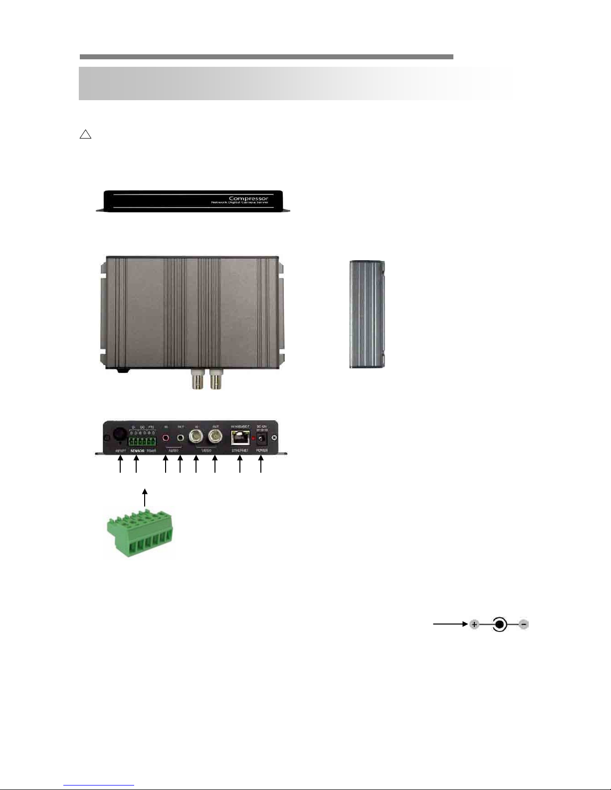
▲ APPEARANCE
EXTERNAL
1. Reset (Factory Default Switch)
2. Sensor Input/Output
3. Stereo Jack)
4. Stereo Jack)
Video Input (BNC Connector)
6. Video Output (BNC Connector)
7. 10/100 Base-T LAN
CP-01 is PoE Ready.
8. Power (12V, 1000mA)
▶ Front
▶ Top
▶ Side
▶ Rear
1 2 3
4
6 7 8
CAUTION:
Check for polarity when using a PoE (Power over Ethernet) power supply.
- Support: IEEE 802.3af
Page 6
Compressor
Compressor 6 / 49
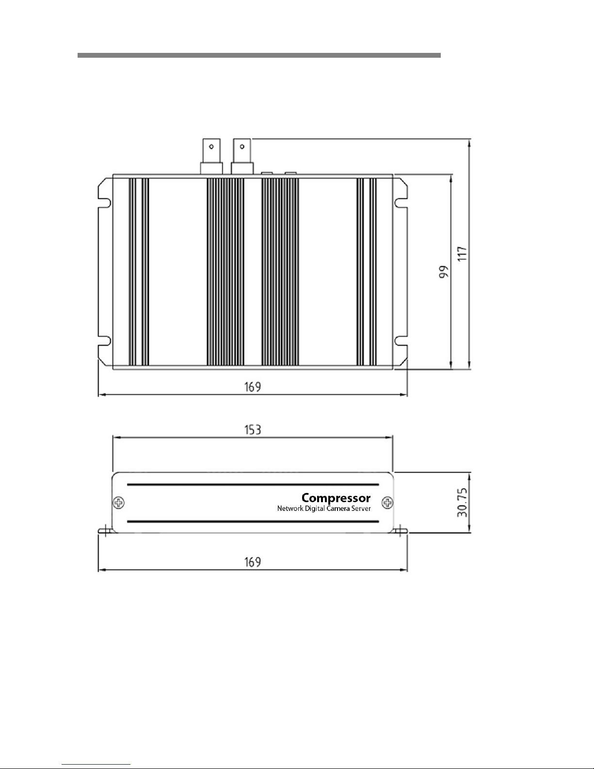
▲ DIMENSION (mm)
Page 7
Compressor
Compressor 7 / 49
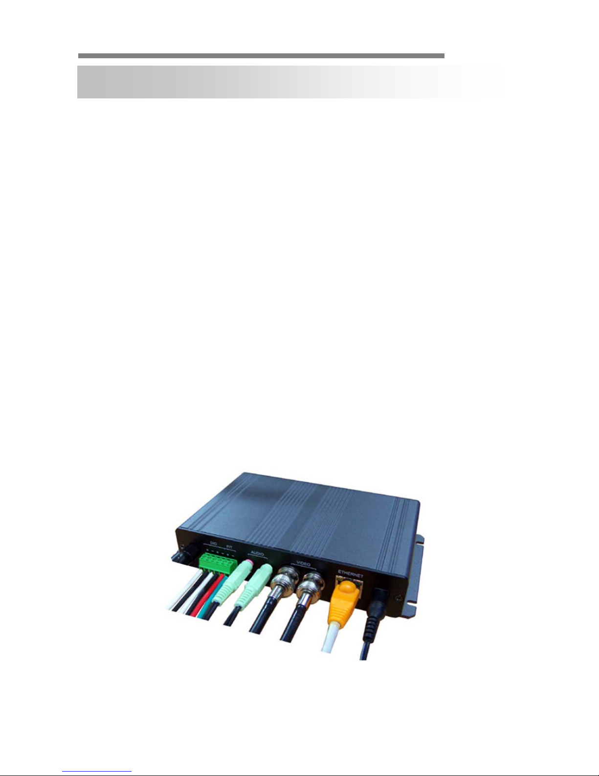
▲ CONNECTION
• DC 12V - Power (Adapter, DC 12V/1000mA)
• ETHERNET - LAN cable (RJ45 Jack)
- A client PC or a network device is connected to the Compressor.
• VIDEO - Video cable (BNC Jack)
- IN: Input
- OUT: Mode Selectable Output
(Connected Camera or Received Image Over IP)
• AUDIO
- IN: Input from a microphone (Ø3.5 stereo jack)
- OUT: Output to a speaker (Ø3.5 stereo jack)
• DIO, PTZ – Control Cable
- DIO: In case a sensor or an alarm device is being used.
- PTZ: In case pan/tilt/zoom control (RS485) is being used.
INSTALLATION
▶
Connections – Power, LAN, Video, Audio, P/T, DIO
Page 8

Compressor
Compressor 8 / 49
▲ INSTALLATION PROCESS
1. Connecting power supply, LAN, and audio cables to the Compressor
※ Network Configuration Example
NETWORK CONFIGURATION
Local Monitoring
CP
(Decoder)
Center Monitoring
NETWORK
CP
(Encoder)
Page 9
Compressor
Compressor 9 / 49
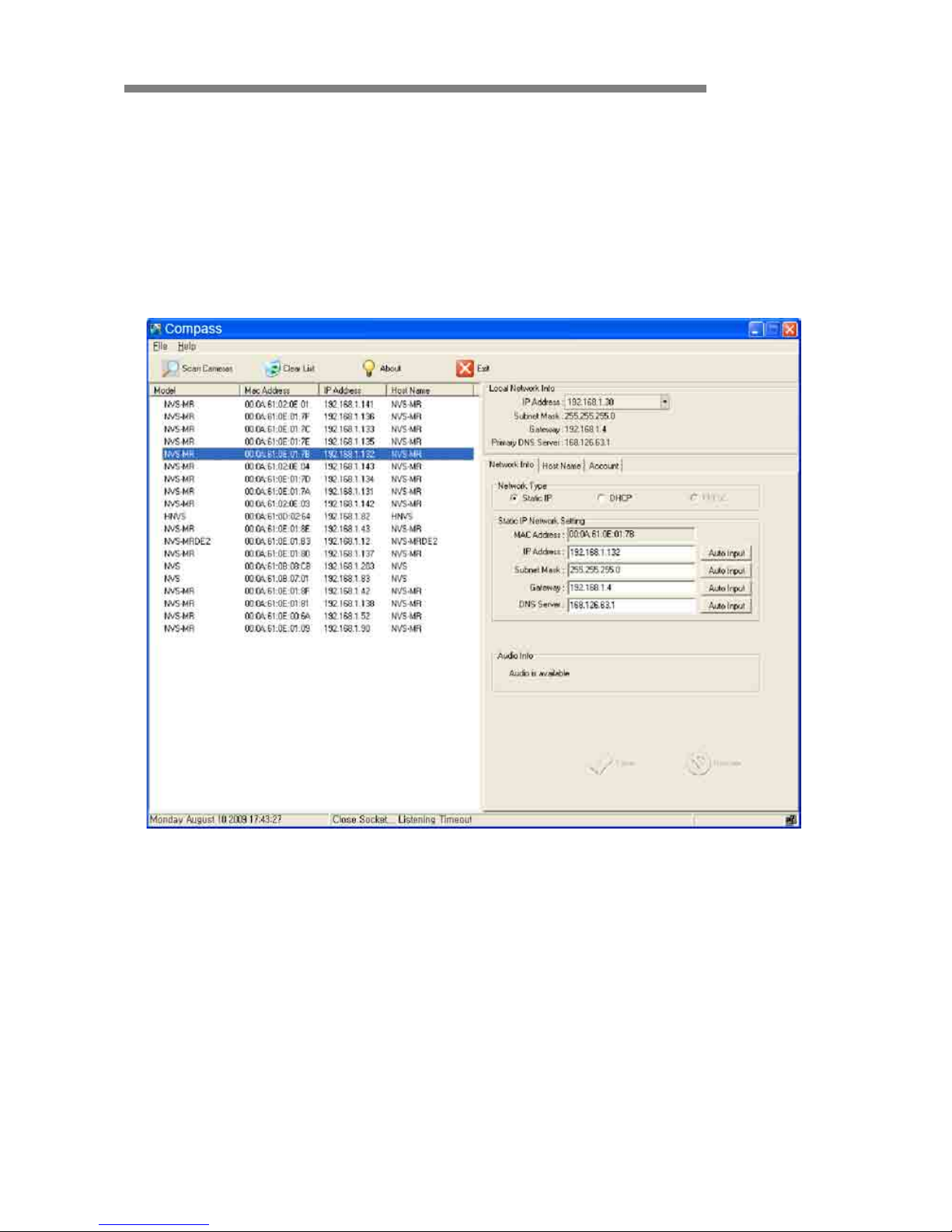
2. Assigning an IP Address to the Compressor
- Assign an IP address with Compass, which is an Easy Network Configuration
Program
- Running Start > Program > NVS 4.1 > Compass
▶
Compass 2.0
Page 10
Compressor
Compressor 10 / 49
3. Scan Compressor and Network Configuration
- Click “Scan Devices” button to search for Compressor, Network video Streamer,
on the local network where Compass runs.
- The Device List displays the basic information of the searched Compressor on the
local network. ( D efault IP address of the Compressor is 192.168.1.2.)
- Select a Compressor and change the network setup appropriately.
- After the setup, click “S av e” butt on.
- Refer to “Compass” manual for details.
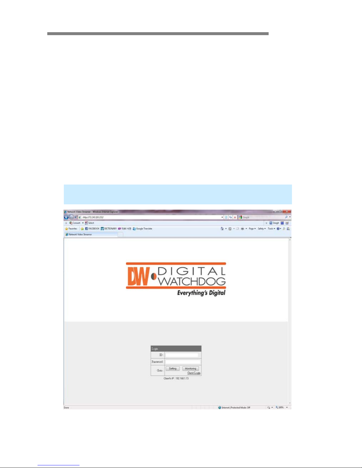
4. Accessing Compressor with a Web Browser
-
Open a web browser on your PC and enter the IP address assigned to the
Compressor in the following format:
http://72.243.193.232/
▶
Login Page
Page 11

Compressor
Compressor 11 / 49
▲ OVERVIEW
• User can manage the Compressor and monitor the video and audio through a web
browser or Pivot CMS.
• User can select the type of encoder mode and decoder mode through a web browser.
• Basic functions
- Monitoring the video and audio data from Compressor
- Changing the setup related to monitoring
- (Resolution, Information Display, D/O (Digital Output), Bitrate, Audio, PTZ, etc.)
- Confirming the status of Compressor
- (Network Status, Model Info, Connection List, Log)
- Changing the basic setting (Network, Video, Audio, Event, Date/Time, OSD)
- Changing the expert setting (RS485, RS232, Port, Security Level, Account,
- DDNS, UPnP, Motio n Detect, Firmware Update)
Using Web Browser
Monitoring
Managing
<the initial page>
Page 12
Compressor
Compressor 12 / 49
▲ CONNECTION
• To connect to the Compressor, type the given IP address on the address bar of a web
browser in the same format that is given below.
(Refer to “Compass” program manual to set IP address of the Compressor.)
• Connection and Accounts
① Administrator Account
- The account is permitted to monit or and manage Compressor.
- Default User ID/Password of the administrator is root/pass.
- Only the password can be changed. Administrator’s ID is fixed.
② Guest Account
- The account is only permitted to use a limited number of monitoring functions.
- In the monitoring page, it shows as inactive for the prohibited features.
http:// (Compressor IP Address)
http:// 192.168.1.2
► Type on the address bar of a web browser and press enter.
► Example: Default IP Address
► Login Window
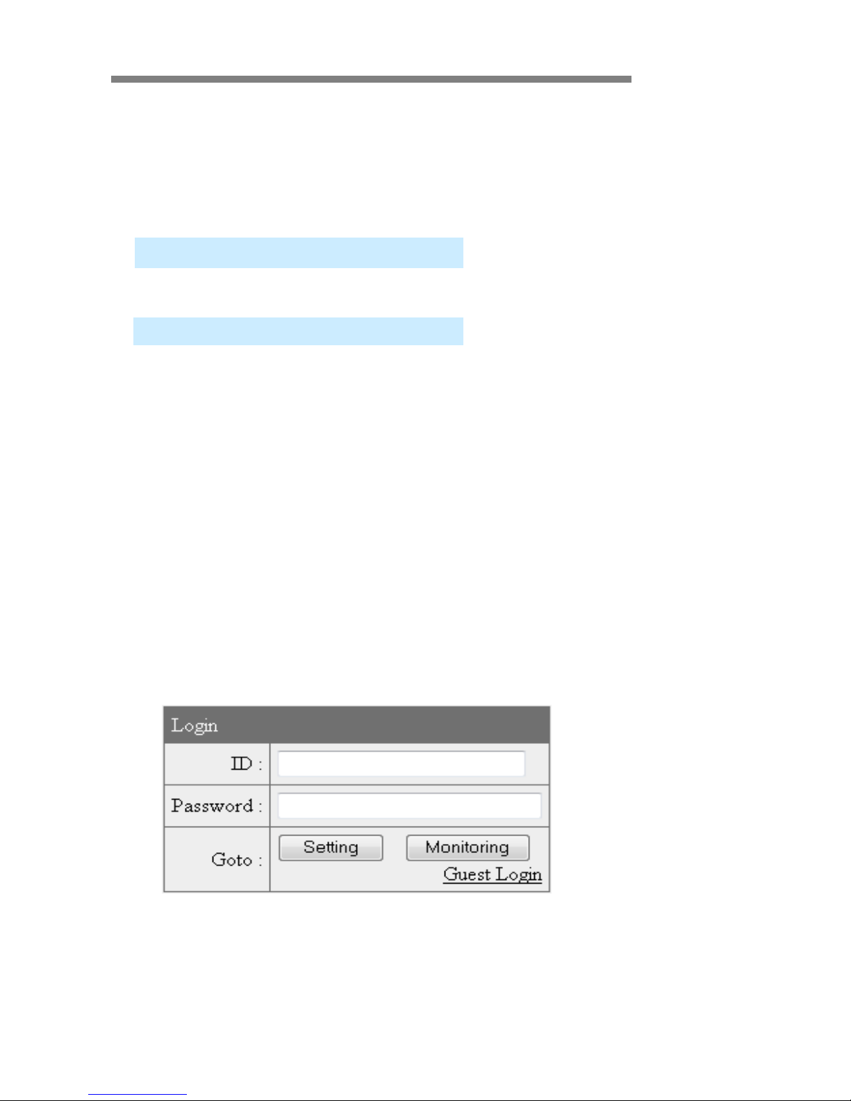
Page 13
Compressor
Compressor 13 / 49
Setting Page Login: Type the User ID and Password of the administrator and click
“Setting” button.
Monitoring Page Login: T ype the User ID and Password of the administrator and
click “Monitoring” button.
Guest Login: Click “Guest Login” to enter the monitoring page of the guest accou nt.
Client’s IP: Displays the IP address of the connected PC.
► Monitoring Page
► Server Setting Page
Page 14

Compressor
Compressor 14 / 49
• Note for Monitoring Page
- CASE ①:
If the “security warning” window appears when first connecting to the monitoring
page, click “Yes” to download ActiveX.
Click the yellow information bar to download ActiveX control.
①
②
Page 15
Compressor
Compressor 15 / 49
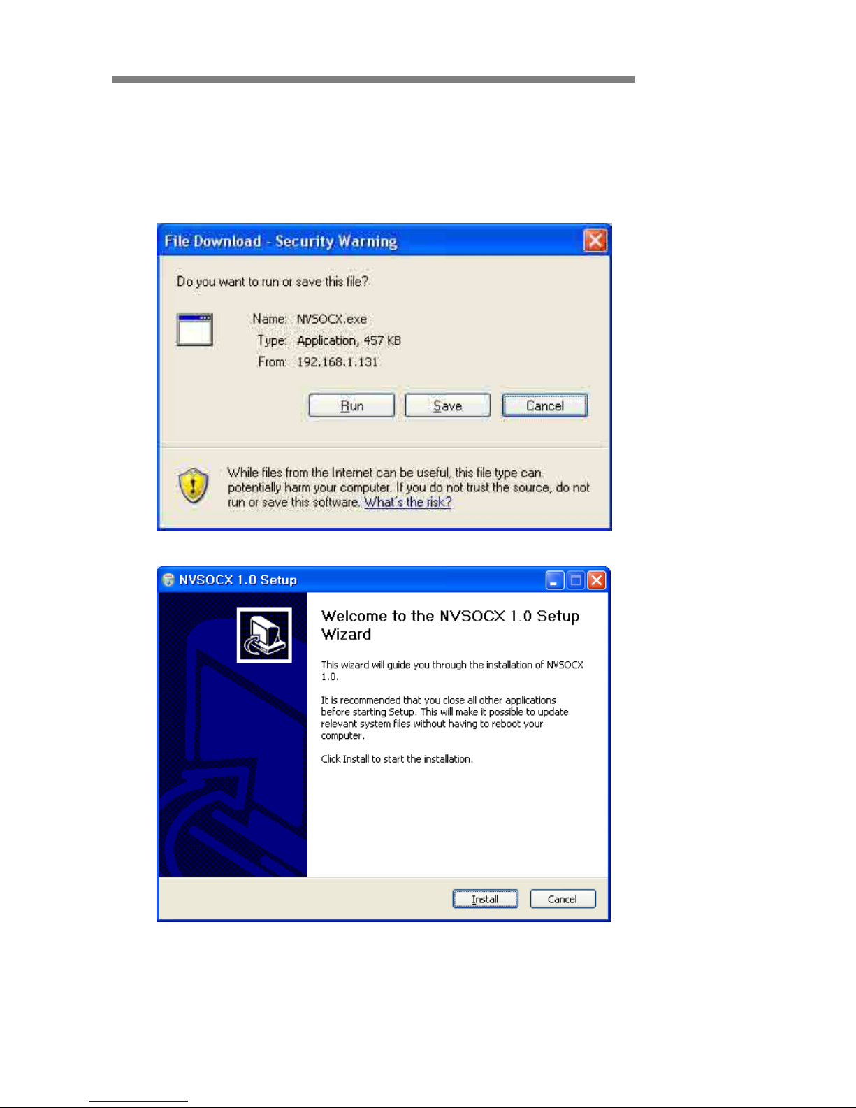
- CASE ②:
User can download and install ActiveX manually if the information bar does not
appear.
Click “Run” button to install ActiveX file manually. (NVSOCX.exe)
► ActiveX Setup Window
Page 16

Compressor
Compressor 16 / 49
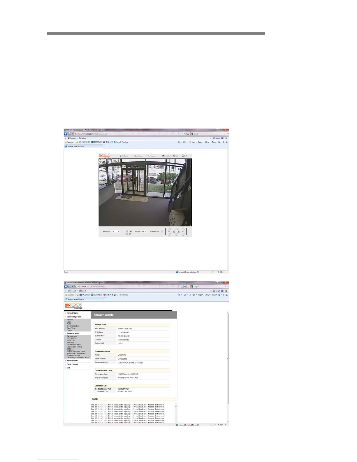
▲ MONITORING
• 1st / 2nd / 3rd Stream
- Select a Stream to the moni t or.
- If the stream button is inactivated, check the video setting of “server setting page.”
• Snapshot
- Capture a JPEG Image of the current video stream.
(JPG file creation route: C:/root)
Monitoring Page
Page 17

Compressor
Compressor 17 / 49
• REC
- Record a video of the current video stream.
(A VI file creation route: C:/root)
• Full
- Extend the image of the current vi deo str ea m to fit mo nit or size.
• Resolution
- Display a current resolution.
- User can select other resolutions.
- If Compressor is rebooted, the resolution on the monitoring page is initialized to the
designated value of “server setting page.”
- Changing the resolution is not available on a guest account.
• Information
• Shows the information of the transferred data from the Compressor above
the image.
• FPS / Camera (Channel) Name / Resolution
• Event Status: Motion Detect (Red) / Digital IN (Blue) / Video Signal (Green)
Resolution QQVGA QCIF QVGA CIF VGA 4CIF D1
NTSC 160x112 176x112 320x240 352x240 640x480 704x480 720x480
PAL 160x112 176x144 320x240 352x288 640x480 704x576 720x576
Detect Video S
ignal
Detect Motion E
vent
Detect Sensor Input (Digital IN)
FPS of Current Video Stream
Resolution of Current Image
Channel Name
Page 18

Compressor
Compressor 18 / 49
• D/O
• Digital Out: Controls the device that is connected to the Compressor.
• Bitrate
• Displays the bitrate of current video stream.
• User can select other bitrate. (If Compressor is rebooted, the bitrate on the
monitoring page is initialized to the designated value of “server setting page.”)
• Changing the bitrate is not available on a guest account.
• Enable Audio
• If the box is checked, the Compressor sends the audio data along with the video
data.
• PTZ Control
• User can control PTZ camera or receiver through RS485.
• Z (Zoom): Zoom In (+) / Zoom Out (-)
• Pan/Tilt: Compressor does not support Pan/Tilt function.
• F (Focus): Focus In (+) / Focus Out (-)
• PTZ control is not supported on a guest account.
Page 19

Compressor
Compressor 19 / 49
▲ SERVER SETTING
• To apply the changed setting, reboot Compressor.
(Click Reboot on the menu.)
• Network Status
• The initial page of Server Setting
• Shows network status, product information, current network traffic, connection list,
and log file.
Page 20

Compressor
Compressor 20 / 49
• Network Status
• MAC Address: Media Access Control Address of Compressor (Unchangeable)
• IP Address: The Assigned IP Address of Compressor
• Subnet Mask: Subnetwork of the IPA
(Use this value to fit the network environment.)
• Gateway: Gateway Address (Use this val ue to fit the network environment.)
• Default DNS: IP Address of Default DNS Server
• Connection Lis t
• User can check the number of connected clients and IP addresses.
• Log
• “Log” displays the logs of general events of Compressor
Page 21

Compressor
Compressor 21 / 49
• Basic Configur ation > Network (Wired)
• User can set Network Information of Compressor (IP Address, Subnet Mask,
Gateway, and Default DNS).
① Static IP
• IP Address: Ask network administrator for an appr o pr i ate addr ess.
• Subnet Mask / Gateway / Default DNS: Ask network administrator.
• After setting, click “Save” button.
• Click “Reboot” to apply the setting(s) to Compressor.
Click!
<Reboot Message>
Page 22

Compressor
Compressor 22 / 49
② Dynamic IP
• If DHCP server is on the local network and you intend to allocate IP address
dynamically , use the following method:
• Select Dynamic IP tab, click “Save” button, and reboot Compressor.
• If y ou want to select Dynam ic IP, set Dynamic DNS to access Compressor.
Page 23

Compressor
Compressor 23 / 49
③ PPPoE
• Use in case the network supports PPPoE like ADSL.
• Ask ISP (Int ernet Ser vice Pr ovid er) for detai ls.
• User ID: ADSL us er ID
• User Password: ADSL user password
• MTU: Maximum Transmission Unit of Data
• IP address of DNS sever can be set to create automatically.
• If your ADSL does not use static IP type, you should use Dynamic DNS setting like
DHCP.
Page 24

Compressor
Compressor 24 / 49
• Basic Configuration > Video
• User can select the streaming type (Encoder or Decoder Mode).
• Compressor supports only an Encoder mode
① Encoder Mode
Page 25

Compressor
Compressor 25 / 49
Video Setting
• Preview: User can check the current video setting through the preview images.
1st / 2nd / 3rd Stream are selectable.
• Video Compr ession Type: H.264 / MJPEG
Compression Type o f 3rd Stream is MPEG4.
• Resolution: QQVGA / QCIF / QVGA / CIF / VGA / 4CIF / D1
Resolution of 3rd Stream: QCIF Fixed
• Bitrate Type: CBR / VBR
• Constant Bitrate: 8M / 7M / 6M / 5 M / 4M / 2M / 1.5M / 1M / 750K / 500K / 384K /
256K / 128K / 64K / 32K
• Variable Bitrate: 1~6 (The highest quality is “1.”)
• Frame Per Sec : 1 ~ 30 (NTSC) / 1~25 (PAL)
• Group Size: 1~200 ( NTSC / PAL)
• Port: Video and Audio Streaming Port (Each stream must use a dif ferent port.)
• Video Type: NTSC / PAL
• Video Color: Auto / Color / B&W
• Aperture: 0~15 (Maximum Emphasis Val ue is “15 .”)
• Brightness / Contrast / Saturation / Hue: 0~255
• X / Y Offset: 1~21
JPEG Capture
• Enable: Send JPEG Image via HTTP Protocol. (1fps fixed)
• Resolution: Select a resolution (QQVGA~D1).
• Quality: High / 1 / 2 / 3 / 4 / Low
▶ JPEG Capture
Page 26

Compressor
Compressor 26 / 49
② Decoder Mode
Server Setting
• IP : IP Address of the Encoder
• Port: Video/Audio Port of the Encoder
• ID: ID of the Encoder
• Password: Password of the Encoder
*User can check the received video of the Encoder through the preview images.
Video Setting
• Brightness / Contrast / Saturation / Hue: 0~255
Page 27

Compressor
Compressor 27 / 49
•
Basic Configuration > Audio
Server to PC Audio Option
• Audio T y pe: Mono (Fixed)
• Audio Codec: G.711 / G.726
• Sampling Rate: 8kHz / 32kHz
• Volume: -34.5~12dB
Page 28

Compressor
Compressor 28 / 49
•
Basic Configuration > Event Notification
① Digital Input
Page 29

Compressor
Compressor 29 / 49
Common
- Sensor Type: Select from two types.
Preset
- Preset Enable: Enables the Compressor to send the preset signal to the connected
camera that supports preset function.
- Preset Number: A number assigned to the camera to support preset function
Digit al O utput
- Digital Output Enable: Enables the Compressor to send the digital signal to the
connected device.
- Digital Output Time: Adjusts the time for when the Compressor should send the signal
(unit:sec).
FTP
- Enable: Enables the Compressor to send a captured image to the FTP server.
- JPEG Capture is available in the video setting page.
- Server: IP Address of FTP Server
- Port: FTP Server Port
- User: Account of FTP Server
- Password: Password of FTP Server
- Image Name: File Name of Captured Image
- Time information will be added with the image name.
SMTP (e-mail)
- Enable: Enables the Compressor to send a captured image via e-mail.
- Outgoi ng m ail s erv er: SMT P Serv er
- To e-mail address: E-mail address of receiver
- From e-mail address: E-mail address of sender
- Subject: User can specify e-mail title.
- Body: User can specify e-mail message.
Page 30

Compressor
Compressor 30 / 49
② Motion Detection
Preset: Same as “Digital Input” Setting
Digit al O utput : Same as “Digital Input” Setting
FTP: Same as “Digital Input” Setting
SMTP (E-mail): Same as “Digital Input” Setting
Page 31

Compressor
Compressor 31 / 49
③ Periodic Timer
Common
- Periodic T imer Enable: Enables the Compressor to send the signal to the client PC
periodically
- Time Interval: Period in Seconds
Preset: Same as “Digital Input” Setting Form
Digit al O utput : Same as “Digital Input” Setting Form
FTP: Same as “Digital Input” Setting Form
SMTP (E-mail): Same as “Digital I nput” Setting
Page 32

Compressor
Compressor 32 / 49
•
Basic Configuration > Date / Time
① Current Time Set
Date / Time
- Server Ti me: T ime that the Compressor internally keeps
- New Date/Time: S pecific time that is voluntarily assigned by the user
Page 33

Compressor
Compressor 33 / 49
② Time Server
Time Server
- Enable: Enables the time of the Compressor to synchronize with the time server
periodically.
- Interval: Period in Seconds
- Time Zone: Selected by the user .
- Daylig ht Saving T ime: Check this box if using daylight savings time.
- Time S erver: User assigns a T ime Server to apply the current time to the Compressor.
- When finished setting, click the “Save” button and reboot the Compressor.
Page 34

Compressor
Compressor 34 / 49
• Basic Configuration > Display
Page 35

Compressor
Compressor 35 / 49
T ext Color
- Background Color: Select a background color.
- Foreground Color: Select a text color.
- Transparency: 0~10
OSD
- Font Size: Normal or Big
- Date Enable: Display Date
- Time Enable: Display T ime.
- Channel Enable: Display channel name.
- X Axis: Input a point on the X coordinate / Horizontal.
- Y Axis: Input a point on the Y coordinate / Vertical.
Logo
- This is the image that is displayed on the OSD of the transferred image.
- First, upload the logo image (BMP file) on “Expert/Firmware Update/OSD Logo Upload.”
- Enable: Check the box to display the image.
- X Axis: Input a point on the X coordinate / Horizontal.
- Y Axis: Input a point on the Y coordinate / Vertical.
Date / Time / Channel Name
OSD Logo
Page 36

Compressor
Compressor 36 / 49
• Advanced Option > PTZ / RS232
Channel 1
- Camera Name: The channel name of the OSD
- Select Camera Protocol: Select a model of the connected PTZ camera or receiver.
- Camera ID (Rx Address): The Rx Address of the con nect ed P TZ c amer a or recei v er
- Baud Rate / Data Bits / Parity / Stop Bits: Properly select the value by the receiver
type.
RS232
- Baud Rate / Dat a Bits / Parity / Stop Bits: Properly select the value by the receiver
type.
Page 37

Compressor
Compressor 37 / 49
•
Advanced Option > WEB Port
Web
- Web Port: Default is 80.
FTP
- FTP Port: Default is 21.
Page 38

Compressor
Compressor 38 / 49
• Advanced Option > Security Level Check
Security Level
- HIGH: Only connections from the local area are permitted.
- MEDIUM: Connections from anywhere in the local area are permitted.
- LOW: Connections from anywhere are permitted.
Page 39

Compressor
Compressor 39 / 49
•
Advanced Option > User Account Settings
Account
- The password amendment of administrator account is available.
- The administrator can add up to 5 users and modify the properties for each user.
Guest Permission
- Determines whether or not the guest is given permission to access the Compressor
- Video and audio monitoring is permitted on guest accounts.
Max Client Limit
- The administrator can restrict the number of simultaneous access. (1~20)
Page 40

Compressor
Compressor 40 / 49
•
Advanced Option > DDNS
- DDNS is the function that matches an IP address and a host name.
- If a Compressor has the dynamic IP address, the host name by DDNS (Dynamic
Domain Name Service) must be used instead of the IP address for the credibility of the
network connection.
IPv4 DDNS
- Check the “Enable” box and select one of the following services.
- Both services require some items to be registered on its own service site.
► Using “ddns.nu”
Page 41

Compressor
Compressor 41 / 49
DynDNS
- For use of “ddns.nu,” register at
- Ty pe the registered DDNS ID, DDNS Password, Host Name, and Interval for updating;
click “Save” button; and then reboot the Compressor.
www.dyndns.com
▶ Main Page of “DynDNS”
Page 42

Compressor
Compressor 42 / 49
ddns.nu
- For use of “ddns.nu,” register at www.ddns.nu
- Ty pe the registered DDNS ID, DDNS Password, and DDNS handle; click “Ok” button;
and then reboot the Compressor.
ProutDNS
- ProutDNS is a set of PHP scripts available for you to create your own Dynamic DNS
service.
- Ty pe the DDNS server , the registered DDNS ID, DDNS Password, Host Name, and
Interval for updating; click “Ok” button; and then reboot the Compressor.
※ For details, please refer to user’s guide “DDNS setup.”
▶ Main Page of “ddns.nu”
▶Main Page of “ProutDNS”
Page 43

Compressor
Compressor 43 / 49
• Advanced Option > AUTO IP Broadcast Check
AUTO IP Broadcast Check
- Enable: Check the box to use Compressor’s UPnP (Universal Plug and Play).
- Friendly Name: User can change Compressor’s friendly name.
Page 44

Compressor
Compressor 44 / 49
• Advanced Option > Motion Detect Area Setting
Input Setting
- Check “Enable” box for use of motion detection.
- Detect Area: If the detection area is selected, the color tur ns gr ee n. (I f JPE G c apture is
enabled on the video setting page, user can check a preview image.)
- Sensitivity: 1~30 (Maximum sensitivity in case of the value “1”)
Page 45

Compressor
Compressor 45 / 49
• Advanced Option > Firmware Upgrade
Page 46

Compressor
Compressor 46 / 49
Language
- Language Select: Select a language file.
(After selecting a language file, refresh the web browser. Please push F5 button.)
- Language File: Add a language file.
Firmware Update
- Uploads the newest firmware, when the browsing button is clicked and the new firmware
is found.
Logo Upload
- Changes the logo image file.
- The process is same as “Firmware Update.”
- Use GIF file. (maximum size: 567x175)
OSD Logo Upload
- Changes the logo image on OSD.
- The process is same as “Firmware Update.”
- User has to use file name by “osd_logo.bmp”.
- (maximum size: 120x38)
Control Protocol Upload
- Add a camera control protocol.
Page 47

Compressor
Compressor 47 / 49
•
Advanced Option > Generating Configuration Report
Report
- User can check all the settings for the Compressor.
- User or ins tal le r ca n write memos on the report page.
- User or installer can print out the pages and use it.
Reboot
- To apply the changed setting(s), reboot the Compressor.
Logout
- -Go back to the initial connection page.
► Confirmation Dialog
Page 48

Compressor
Compressor 48 / 49
▲ Product Specification
SPECFICATION
CP-01 CP-04
O/S
1 Ch 4 Ch
G.711/G.726 G.711/G.726/ADPCM
1 Ch Input / 1 Ch Out put 4 Ch Input / 1 Ch Out put
Software
W eb (IE)
Backup
12V x 1A D/C Adapt er, P oE 12vx1A D/ C A dapter
300 mA 400 mA
169mmx117m m x 31m m / 345
224mmx160m m 44m m / 930
-20°C ~ 74°C -20°C ~ + 74°C
-10°C ~ 55°C / 20 ~ 90% RH 0°C ~ 40°C / 20 ~ 90% RH
Physical
Dimens i on and Wei ght
St orage Temperature
Operati ng Temperature and
Humidity
Remote M anagem ent
DW -NEXUS, DW-Pi vot, DW-Hybri d DVR, We b Browser
Live Monitoring, Pl ayback , and Syst em Configurat i on
External
Local B ack up by S D/ SDHC Card
Power
Consumption
RS-485 Port
1 Ch for PTZ Camera
LAN
10/100 B ased-T (RJ45) - Fixed IP, DHCP , & DDNS
Mobil e Device Support
iPhone, B l ack berry , 3G M obi l e
IO Control
Alarm Input / Rel ay Out put
I Ch Input / 1 Ch Output
RS-232 Port
1 Ch for Ext ernal Cont rol Device
AC/ DC Adapter
Bitrate
Input / O ut put Compress i on
Line Input
1.0 V RM S
Line Out put
1.0VRMS
Input
Model
Compressor (CP)
Operati ng S ys tem
Linux
Video
Compressi on A l gori t hm
H.264/MJPEG
Resolution
D1/Ha l f D1/2CIF/CIF/Q VGA/ Q CIF
Compressi on A l gori t hm
Bi-Directional
Network
Audio
Two Way, Ful l Duplex
32Kbps ~ 4M bps
Frame Rat e
30 fps in A l l Resolutions
Streaming
H.264 Dual S tream or S i m ul taneous H. 264 and M JP E G
Page 49

Compressor
Compressor 49 / 49
▲ Recommended Specifications of External Devices
Item Specification
Network 10/100 Base-T LAN (Dedicated IP line, ADSL, Cable Modem)
Client PC
Processor Pentium Dual Core or Above
RAM 2GB or Above
Graphic Card 512MB or Above
OS Windows 2003 / XP / Vista / 7
Monitor 1024 X 768 Pixels or Above
 Loading...