

Page 1

DW-CP04 Compressor-
Analog to IP Signal Converter
User’s Manual
Version 1.1
Class A Digital Device (industrial & commercial environment)
This equipment has been tested and found to comply with the limits for a Class A digital device, pursuant to CE
and FCC Rules. These limits are designed to provide reasonable protection against harmful interference when the
equipment is operated in a commercial environment. This equipment generates uses and can radiate radio
frequency energy and, if not installed and used in accordance with the instruction manual, may cause harmful
interference to radio communications. Operation of this equipment in a residential area is likely to cause harmful
interference in which case the user will be required to correct the interference at his own expense.
Page 2

DW-CP04 Manual
01Manual_CP04_05172013 2
DW-CP04 User’s Manual
Digital Watchdog®
Manual Edition 05172013– May 2013
©2000-2013 DIGITAL WATCHDOG, INC.
All Rights Reserved.
DIGITAL WATCHDOG, INC.
Tampa, FL ● USA
Technical Support
For technical support call, email, or visit our web site.
USA & Canada 1+ (866) 446-3595
International 1+ (813) 888-9555
French Canadian 1+ (514) 360-1309
Email: sales@dwcc.tv
Web site: www.digital-watchdog.com or dwcc.tv
Page 3

DW-CP04 Manual
01Manual_CP04_05172013 3
Contents
1. PRODUCT OVERVIEW .......................................................................................................................... 8
1.1. DW-CP04 ........................................................................................................................................................................ 8
1.2. KEY FEATURES ................................................................................................................................................................... 9
1.3. TECHNICAL SPECIFICATION ........................................................................................................................................... 10
1.4. DW-CP04 PACKING LIST ............................................................................................................................................ 12
2. PRODUCT DESCRIPTION ................................................................................................................... 13
2.1. DW-CP04 FRONT VIEW .............................................................................................................................................. 13
2.2. DW-CP04 REAR VIEW ................................................................................................................................................ 14
2.2.1. CTL Port Description .......................................................................................................................................... 15
2.2.2. RS-232 Interface .................................................................................................................................................. 15
2.2.3. RS-485 Connection ............................................................................................................................................. 15
2.2.4. DI Connection ....................................................................................................................................................... 15
2.2.5. DO Connection ..................................................................................................................................................... 15
3. DW-CP04 INSTALLATION AND BASIC SETUP............................................................................... 16
3.1. BEFORE INSTALLATION .................................................................................................................................................. 16
3.2. FACTORY DEFAULT SETTINGS....................................................................................................................................... 16
3.3. INSTALLING THE DW-CP04 ........................................................................................................................................ 16
4. IP INSTALLER ....................................................................................................................................... 17
4.1. ABOUT THE IP INSTALLER ............................................................................................................................................. 17
4.2. INSTALLING AND UNINSTALLING THE IP INSTALLER ................................................................................................ 17
4.2.1. Installing IP Installer ........................................................................................................................................... 17
4.2.2. Uninstalling IP Installer ..................................................................................................................................... 18
4.3. USING THE IP INSTALLER .............................................................................................................................................. 18
4.3.1. Staring the IP Installer ...................................................................................................................................... 18
Page 4

DW-CP04 Manual
01Manual_CP04_05172013 4
4.3.2. IP Installer’s Main Window ............................................................................................................................. 18
4.3.3. IP Installer’s Main Window ............................................................................................................................. 19
4.3.4. Manual Network Setup .................................................................................................................................... 19
4.3.5. Automatic Network Setup .............................................................................................................................. 20
5. COMPRESSOR’S WEB VIEWER ......................................................................................................... 21
5.1. ENTERING LIVE VIEW ..................................................................................................................................................... 21
5.1.1. Single-Mode View............................................................................................................................................... 22
5.1.2. Multi-Mode View ................................................................................................................................................ 22
5.1.3. Image Snapshot ................................................................................................................................................... 22
5.1.4. Image Clip .............................................................................................................................................................. 22
5.1.5. Instant Recording ................................................................................................................................................ 23
5.1.6. Instant Playback ................................................................................................................................................... 23
5.1.7. Extended Features .............................................................................................................................................. 23
5.1.8. Video Control ........................................................................................................................................................ 24
5.1.9. Audio Control ....................................................................................................................................................... 24
5.1.10. PTZ Control ......................................................................................................................................................... 24
5.2. ENTERING THE SMART PLAYER .................................................................................................................................... 25
5.2.1. Smart Player’s Main Screen ............................................................................................................................ 25
5.2.2. Searching Video ................................................................................................................................................... 25
5.2.3. Extra Features ....................................................................................................................................................... 26
5.3. ENTERING ADMIN MENU ............................................................................................................................................. 27
5.4. ADMIN MENU STRUCTURE........................................................................................................................................... 28
6. QUICK CONFIGURATION .................................................................................................................. 29
6.1. STEP-1 SERVER NAME SETUP ...................................................................................................................................... 29
6.2. STEP-2 LOCAL DATE & TIME CONFIGURATION ....................................................................................................... 29
6.3. STEP-3 NETWORK CONFIGURATION .......................................................................................................................... 29
Page 5

DW-CP04 Manual
01Manual_CP04_05172013 5
6.4. STEP-4 IP-CCTV DNS™ SETUP ............................................................................................................................... 30
6.1. STEP-5 RECORDING CONFIGURATION ....................................................................................................................... 30
6.2. FINISH .............................................................................................................................................................................. 30
7. SYSTEM CONFIGURATION ................................................................................................................ 30
7.1. SERVER NAME SETUP .................................................................................................................................................... 30
7.2. DATE & TIME ................................................................................................................................................................. 31
7.3. ADMINISTRATOR PASSWORD ....................................................................................................................................... 31
7.4. ACCESS CONTROL .......................................................................................................................................................... 32
7.5. USER REGISTRATION ...................................................................................................................................................... 32
7.5.1. Add ............................................................................................................................................................................ 32
7.5.2. Edit ............................................................................................................................................................................. 33
7.5.3. Delete........................................................................................................................................................................ 34
8. NETWORK CONFIGURATION ........................................................................................................... 34
8.1. NETWORK CONFIGURATION......................................................................................................................................... 35
8.1.1. Static IP Configuration ...................................................................................................................................... 35
8.1.2. DHCP Client Configuration ............................................................................................................................. 35
8.1.3. PPPoE Configuration .......................................................................................................................................... 36
8.2. NETWORK PORTS ........................................................................................................................................................... 36
8.3. BANDWIDTH CONTROL ................................................................................................................................................. 36
8.4. VIEW NETWORK STATUS .............................................................................................................................................. 37
8.5. NETWORK STATUS NOTIFICATION .............................................................................................................................. 38
8.6. IP-CCTV DNS™ SETUP ............................................................................................................................................. 39
8.7. PORT FORWARDING & UPNP ..................................................................................................................................... 40
8.8. RTP/RTSP ...................................................................................................................................................................... 41
8.9. SNMP SETUP ................................................................................................................................................................. 42
8. DEVICE CONFIGURATION ................................................................................................................. 43
Page 6

DW-CP04 Manual
01Manual_CP04_05172013 6
8.1. SERIAL PORTS CONFIGURATION .................................................................................................................................. 43
8.1.1. Serial Input Mode ............................................................................................................................................... 43
8.1.2. Serial Output Mode ........................................................................................................................................... 45
8.1.3. Transparent Mode .............................................................................................................................................. 45
8.1.4. PTZ Mode ............................................................................................................................................................... 46
8.2. PRIVACY ZONE ............................................................................................................................................................... 48
8.3. CAMERA & MOTION ..................................................................................................................................................... 49
8.3.1. Camera Configuration ....................................................................................................................................... 50
8.4. DI/DO ............................................................................................................................................................................. 51
8.4.1. DI/DO ........................................................................................................................................................................ 51
8.5. DI STATUS/DO CONTROL ........................................................................................................................................... 51
9. ADVANCED CONFIGURATION ......................................................................................................... 52
9.1. ADVANCED SERVICES .................................................................................................................................................... 52
9.1.1. E-mail Service Configuration ......................................................................................................................... 52
9.1.2. FTP(Buffered)Service Configuration ............................................................................................................ 54
9.1.3. FTP (Periodic) Service Configuration .......................................................................................................... 56
FTP (Periodic) Service Configuration for each Camera ..................................................................................... 56
9.1.4. Sensor Notification ............................................................................................................................................. 57
9.1.5. Alarm Output Service Configuration.......................................................................................................... 58
10. RECORDING CONFIGURATION .................................................................................................... 59
10.1. SD CONFIGURATION ..................................................................................................................................................... 59
10.1.1. SD Status & Format ........................................................................................................................................ 59
10.1.2. SD Information................................................................................................................................................... 60
10.2. RECORDING CONFIGURATION ..................................................................................................................................... 61
10.3. VIEW RECORDING PROFILE........................................................................................................................................... 65
10.4. RECORDING MODE ........................................................................................................................................................ 65
Page 7

DW-CP04 Manual
01Manual_CP04_05172013 7
10.5. SD STATUS REPORT ...................................................................................................................................................... 66
10.6. CLEAR RECORDING CONFIGURATION ......................................................................................................................... 67
10.7. DELETE RECORDED DATA ............................................................................................................................................. 67
11. UTILITIES........................................................................................................................................... 68
11.1. SYSTEM LOG ................................................................................................................................................................... 68
11.2. SAVE CONFIGURATION .................................................................................................................................................. 68
11.3. REBOOT............................................................................................................................................................................ 69
11.4. FACTORY DEFAULT ......................................................................................................................................................... 69
11.5. SYSTEM UPDATE ............................................................................................................................................................. 70
11.5.1. Update by Item ................................................................................................................................................. 70
12. APPENDIX ........................................................................................................................................ 71
12.1. TROUBLESHOOTING THE COMPRESSOR SMART LIVE VIEWER ................................................................................ 71
12.1.1. Installation ............................................................................................................................................................ 71
12.1.2. Server ..................................................................................................................................................................... 71
12.1.3. Video ...................................................................................................................................................................... 71
12.1.4. Audio ...................................................................................................................................................................... 72
12.1.5. PTZ ........................................................................................................................................................................... 72
12.1.6. Relay Output ....................................................................................................................................................... 72
12.1.7. Other....................................................................................................................................................................... 73
Page 8
DW-CP04 Manual
01Manual_CP04_05172013 8
1. Product Overview
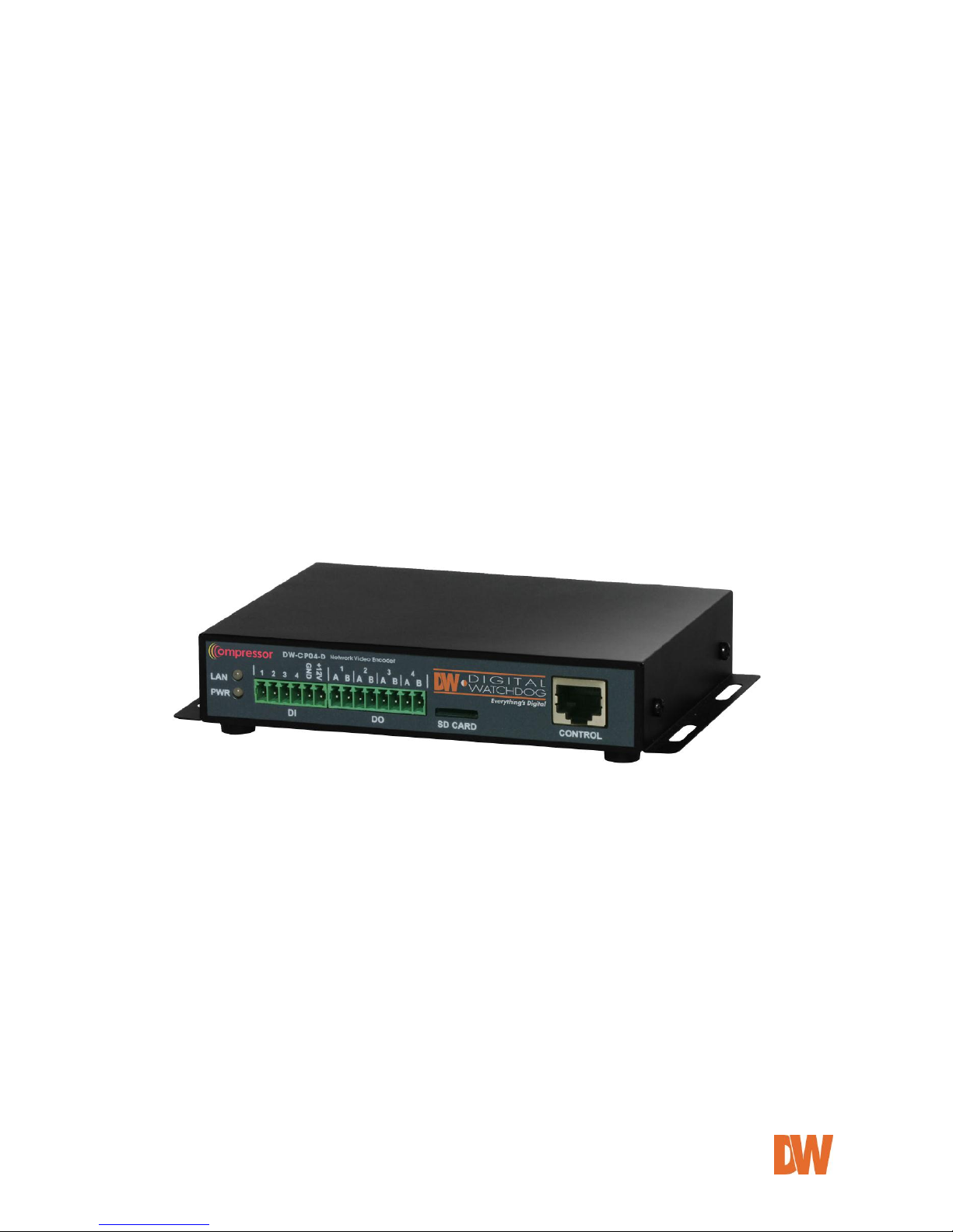
1.1. DW-CP04
Digital Watchdog’s DW-CP04 is a 4ch network video server which transmits digital images captured by
Analog CCD camera over IP (Internet Protocol) network.
It can transmit up to 120fps@D1 over the existing network. You can monitor video of DW-CP04 through web
browser (for example MS Internet Explorer), if DW-CP04 is connected to network. DW-CP04 supports video
compression both MJPEG and H.264 simultaneously so that user can choose appropriate video compression
for the purpose. For both MJPEG and H.264, DW-CP04 provides 6 levels of video quality.
DW-CP04 server is state-of-the art device and leads new generation of monitoring and security solution.
Picture 1 : DW-CP04
Page 9

DW-CP04 Manual
01Manual_CP04_05172013 9
1.2. Key Features
OnVIF Compliant
4CH BNC In
120fps @ D1 Resolution
Dual Codec (H.264/ MJPEG) with Single Stream
Motion Detection
Two- Way Audio
Micro SD Card Interface
RS-232/ RS-485 PTZ Control
Free and Simple DDNS Service
Search and Playback from the software interface
Frame-rate& Bandwidth Control
4 Alarm Inputs, 4 Alarm Outputs
Event Notifications via E-mail with Image
Configuration and control device through Web browser
Page 10

DW-CP04 Manual
01Manual_CP04_05172013 10
1.3. Technical Specification
Hardware
32bit RISC CPU/ Embedded Linux
128Mbytes SDRAM/ 128MByte Flash
Video
compression
H.264/ MJPEG(single stream)
Resolution
NTSC: 704x480, 352x240,160x112
PAL: 704x576, 352x240,160x112
Frame rate
(each channel)
Up to max 120/100 fps@D1
Video Streaming
MJPEG and H.264 Single Streaming (Simultaneously)
Controllable frame rate and bandwidth
Image setting
Compression levels: 6 (MJPEG/H.264)
Color: color, black & white
Transmission
Up to 120fps(NTSC)/100fps (PAL)
when 4channels at D1
Voice
8bit G.711, 8Khz, 8Kbyte/sec
Audio 1ch in & 1ch out
LAN interface
10/100 Base T Ethernet auto sensing
Alarm I/O Interface
4x1 Photo-coupled inputs and 4 Relay output
Video Input
4 Channel Composite Video Input
Serial Interface
COM Port: RS-232
AUX Port: RS-485
COM ports for console, serial input/output device and AUX ports for PTZ or
other RS485 device
Max Baudrate: 115200 bit/s
Security features
Multi user level protection for camera access, PTZ, Alarm I/O
Advanced Service
Up to 5.6M memory for Pre/Post alarm buffer e-mail, FTP, IP notification,
Alarm Notification to e-mail, CGI Call by event or schedule
Built-in Motion detections
Accuracy: 12x12=144 blocks
Motion Sensitivity : -100 ~ 100 : 100 is hypersensitive
PTZ & UART Control
Support
PTZ and UART device control through serial port (RS-232/RS-485) (Support
protocols from Pelco “P”& “D” protocol, Vicon V1311RB, Samsung PTZ,
Honeywell PTZ and X10 Epson Printer)
Others
Time stamp on Video
Transmit External data(ex. POS) transfer with Video
IP notification by e-mail
Management
Configurable by serial, web or telnet
Remote system update via telnet, FTP OR web browser.
Developer support
Provides HTTP CGI API
ActiveX control development kit
PWR Supply
SMPS
Input: 100~240VAC, 50/60 Hz, 300mA
Output: DC 12Volt, 1A, SMPS
Page 11

DW-CP04 Manual
01Manual_CP04_05172013 11
PWR Consumption
DC 12Volt
Max or Peak: 0.6 A
Operating Environment
Temperature : -10° ~ 50°C
Humidity : 10 ~ 90% RH(non-condensing)
Miscellaneous
Work with Smart NVR(CMS software)
Dynamic IP support through IPCCTVDNS Server
Users
128 simultaneous users
Installation & management
Configuration: installation wizard, HTTP, telnet and console Upgrade
Firmware: HTTP, telnet & FTP
Video access from Web
browser
Video access from Web browser
Minimum Web browsing
requirements
Pentium 4, 2 GHz, 2GB(RAM) or higher
Video Card: 256MB RAM, 1024x768 resolution or higher
100Mbps Network Adaptor or faster
Windows XP Pro or later
Internet Explorer 6.x or later
Supported protocols
HTTP, RTP/RTSP, TCP/IP, FTP, Telnet, RARP, PPPoE, SNMP, PAP, CHAP,
DHCP, NTP, SMTP client, uPNP, and etc.
Approvals
KC
FCC : Class A
CE : Class A
RoHS
Dimensions (HxWxD) and
weight
148(W) x 118(D) x 25(H) (in mm)
About 0.25kg without power supply.
Table 1 : DW-CP04 Data Sheet
Page 12
DW-CP04 Manual
01Manual_CP04_05172013 12
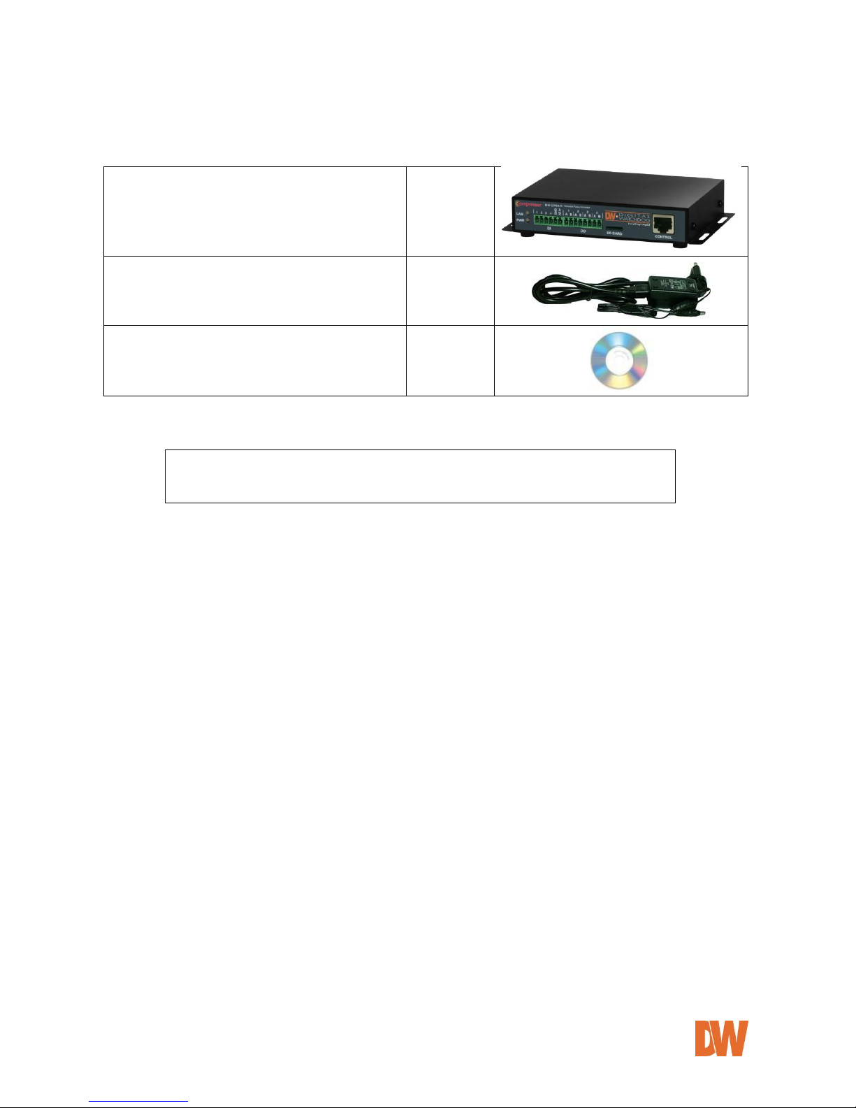
1.4. DW-CP04 Packing List
DW-CP04
1 EA
Power Supply
(Power Cable & SMPS DC12V 1A Adapter)
1 EA
CD (User’s Manual, IP Installer and etc.)
1 EA
Table 2 : DW-CP04 Packing List
Note: Please make sure all the listed items are included in the package. For any
missing items, please contact your local distributor.
Page 13
DW-CP04 Manual
01Manual_CP04_05172013 13
2. Product Description
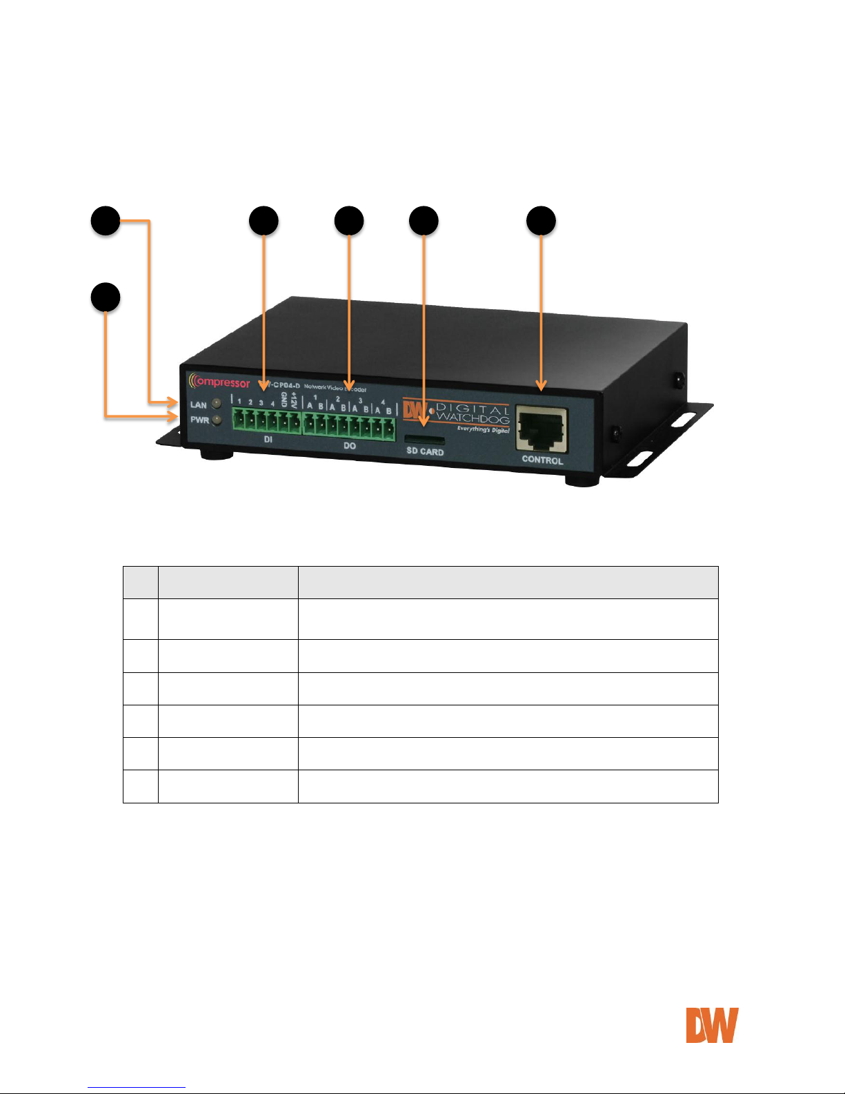
2.1. DW-CP04 Front View
Picture 2 : DW-CP04 Front View
Picture 3 : Enlarged Front LED
Name
Description
A
LAN LINK LED
Indicates the connection status of LAN connector. It goes green when a
physical connection is properly made to the LAN port.
B
POWER LED
This red LED is lit during DW-CP04 is powered on.
C
DI
Sensor/Contact Input Port
D
DO
Beacon/Alarm Output Port
E
SD CARD
Micro SDHC Slot for Onboard Storage
F
CONTROL
CTL Port (RS-485, RS-232, DI, DO)
Table 3 : DW-CP04 Front Panel
E
A B C D E
F
Page 14
DW-CP04 Manual
01Manual_CP04_05172013 14
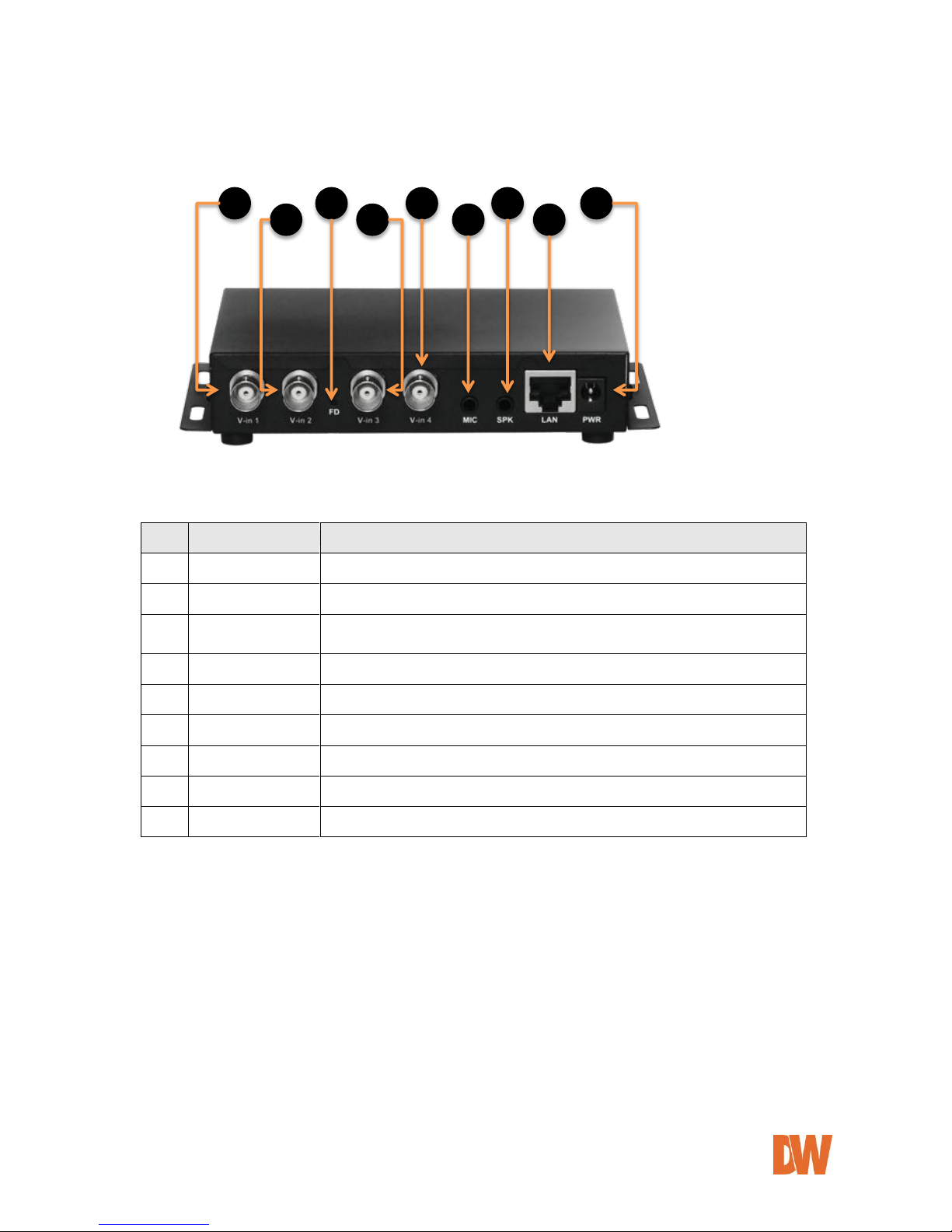
2.2. DW-CP04 Rear View
Picture 4 : DW-CP04 Rear View
Name
Description
A
Video In 1
BNC cable port for Video input of number 1 camera of Module 1.
B
Video In 2
BNC connector for Camera 2
C
FD
Beep one time (0.5 sec) after three seconds and then beep three times shortly
After another three seconds.
D
Video In 3
BNC connector for Camera 3
E
Video In 4
BNC connector for Camera 4
F
MIC
Audio Input Port
G
SPK
Audio Output Port
H
LAN
RJ-45 Network Connector
I
Power
DC 12V 1A
Table 4 : DW-CP04 Rear Panel
A B C D E F G H I
Page 15
DW-CP04 Manual
01Manual_CP04_05172013 15
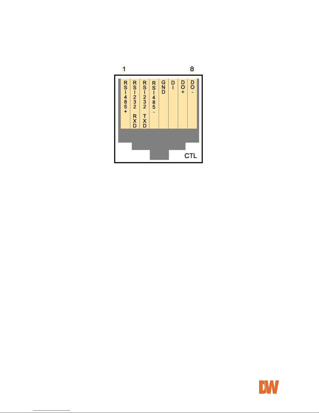
2.2.1. CTL Port Description
The picture below shows how to wire CTL port connector pins for Sensor Input (DI, GND), Relay Out
(DO+, DO-), RS-485 (+, -) and RS-232 (RXD, TXD, GND) signals.
Picture 5 : CTL Port Description
2.2.2. RS-232 Interface
RS-232 Port is provided for a connection with external devices such as water level sensor, speed
sensor, etc. The GND pin for RS-232 is shared with the Sensor Input GND. If the DW-CP04 needs to
be connected to other network devices via RS-232, then RXD and TXD pin may need to be cross-wired.
2.2.3. RS-485 Connection
RS-485 port is a serial interface for communication with external devices such as controlling PTZ,
multiplexers, access control boxes, X10 protocol peripherals, etc. Refer to the individual manuals for
each external device you wish to connect to the DW-CP04 for additional information on protocols and
proper configuration.
2.2.4. DI Connection
DI (Digital In) is a Sensor Input port which can be used for acquiring input signal from an external
device such as sensors, switches, etc. DW-CP04 can recognize the input state if DI+ port is connected
to GND or left unconnected. See 8. Device Configuration for additional information.
2.2.5. DO Connection
DO (Digital Out) is an Alarm Output port which can be used for activating door opener/closers, sirens,
emergency beacons, etc. DO ports are on Open-Collector basis, and driving current must not exceed
100mA at DC 5 to 12Vrange. DW-CP04 activates DO port by turning on or off the Open-Collector
driver. See section- 8. Device Configuration for additional information.
Page 16

DW-CP04 Manual
01Manual_CP04_05172013 16
3. DW-CP04 Installation and Basic Setup
3.1. Before Installation
Read carefully User's Manual.
Check user’s Network (IP Address, Network Mask and default gateway)
Secure an IP address for DW-CP04.
3.2. Factory Default Settings
The following table shows the factory default condition for the Compressor. Please refer to this when
you need to change the values on the admin menu.
Factory Default
Admin ID
root
Admin password
root
IP address
10.20.30.40
Network mask
255.255.255.0
Gateway
10.20.30.1
Table 5: Factory Default
Note: Factory default Admin ID and Password are all lower case letters.
3.3. Installing the DW-CP04
For installation of DW-CP04, please follow the steps below.
1. Place the analog cameras in place and connect power supplies. Consult the cameras’ manual
for additional information.
2. Connect the video output ports of the analog cameras to the video-in ports of the DW-CP04.
3. Connect the DW-CP04 to the desired network by connecting a network cable to the encoder’s
LAN port.
4. Connect the power supply of DW-CP04. To prevent any damage to the device, it is
recommended to plug the power cables to the power supply and only then to the Compressor.
5. Once both LEDs are on you can connect to the DW-CP04’s web viewer. (Power LED should
appear orange, and LAN LED should appear green).
6. To find the Compressor on the network as well as configure its network settings, run the IP
Installer tool available on the complimentary CD accessory.
Page 17
DW-CP04 Manual
01Manual_CP04_05172013 17
4. IP Installer
4.1. About the IP Installer
The IP Installer software can be found in the accessory CD available with the Compressor. The IP
Installer is utility program designed to locate all DW-CP04 Compressors on your network. By using
the IP Installer, users will be able to:
Setup the Network Configuration of the Compressor.
Runs on Microsoft Windows operating system (XP, Vista, 7)
Searching for Network Cameras, Video Servers, and Network Video Recorders
Remotely upgrade the Compressor’s Firmware
Support automatic and manual IP setup
4.2. Installing and Uninstalling the IP Installer
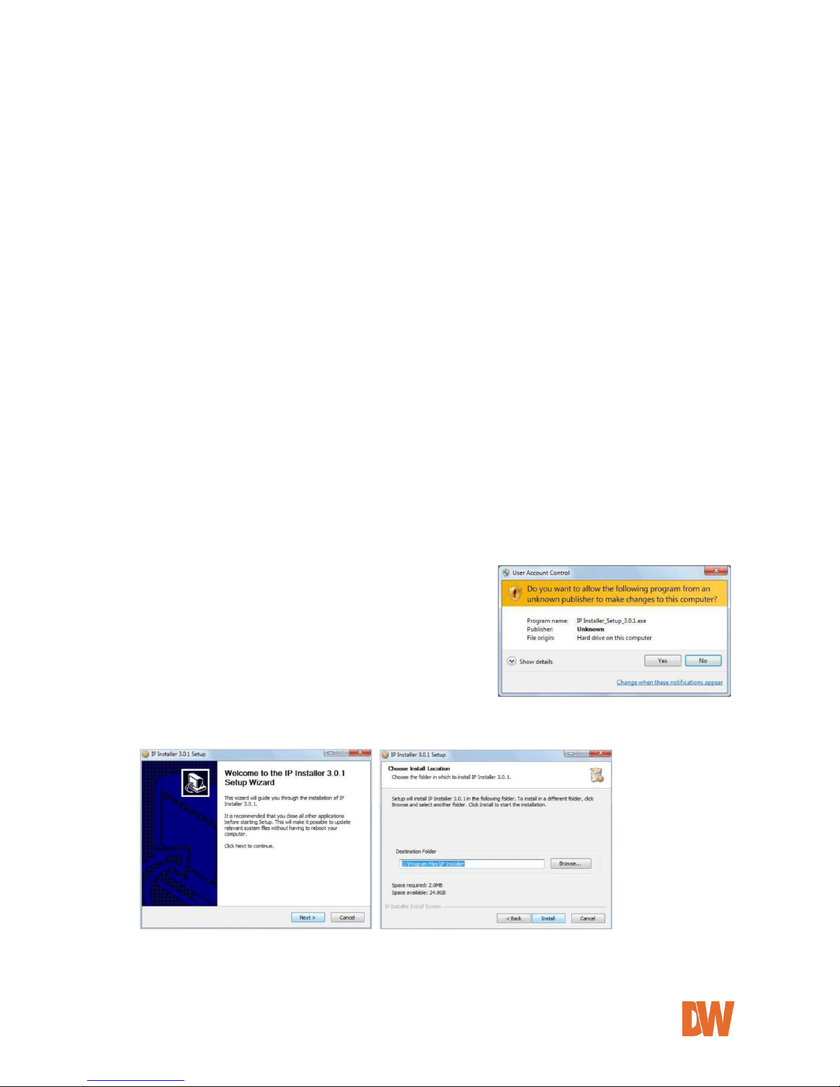
4.2.1. Installing IP Installer
Insert the CD to the ODD tray and check the installation file.
You may see a consent prompt for running this install program, which is an User Account Control of the
Windows as shown below-
Click 'Yes' button, then the installation wizard window will appear. Click ‘Next’.
If necessary, click the Browse button to choose a proper path for the installation.
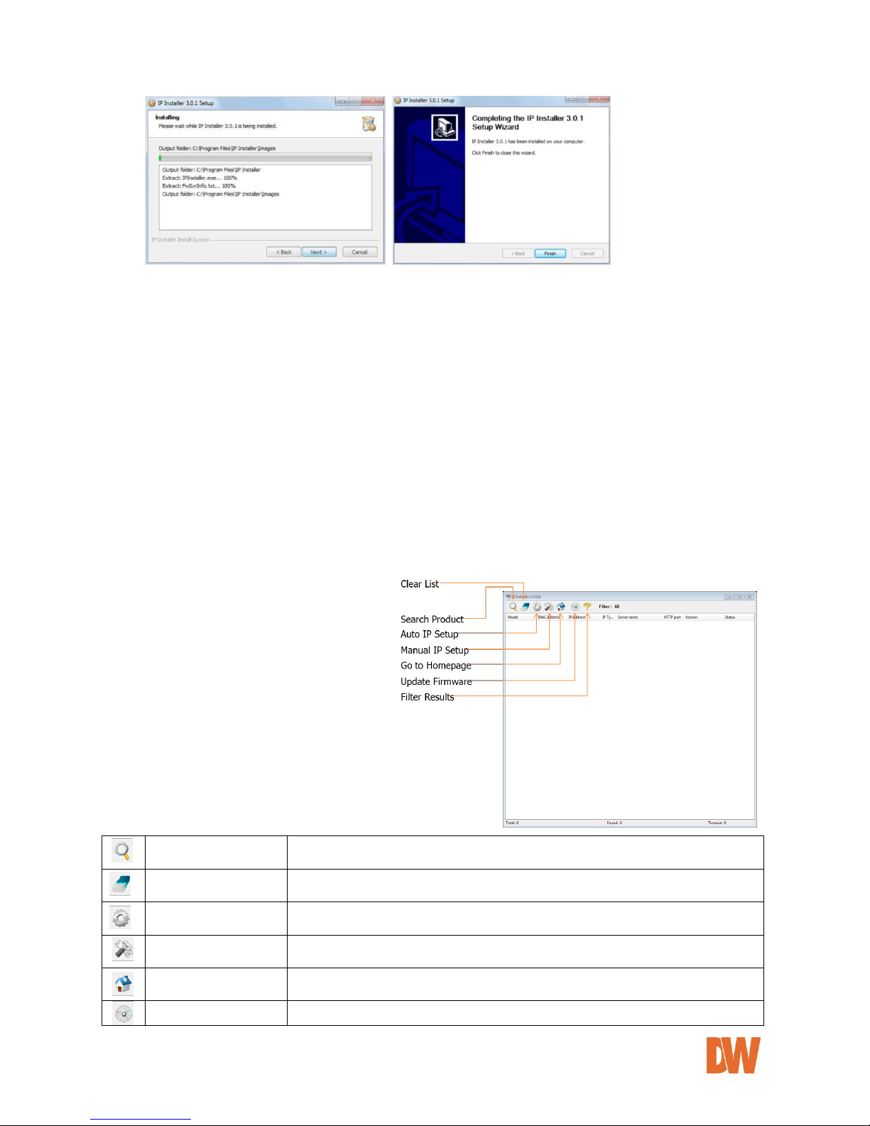
Click ‘Install’. You will see the progress of the installation as shown below.
Click 'Finish' when the installation process is complete.
Page 18
DW-CP04 Manual
01Manual_CP04_05172013 18
4.2.2. Uninstalling IP Installer
If you want to remove the IP Installer program from your PC, click Start > All Programs > IP Installer >
Uninstall. You may see a consent prompt for running this install program. Click ‘Yes’ to continue.
Follow the installation wizard to complete the uninstall process and remove the IP Installer software
from the PC.
4.3. Using the IP Installer
4.3.1. Staring the IP Installer
Start the ‘IP Installer’ by double clicking the newly created Desktop shortcut icon.
Or you can also start the program by clicking Start > All Programs > IP Installer > IP Installer.
4.3.2. IP Installer’s Main Window
Search Product
Scan the network and show all the DW-CP04 products that are on the
network.
Clear Product List
Clear the DW-CP04 products list created by searching the network.
Automatic IP Setup
Configure the network setting of selected IP device in Automatic mode.
Manual IP Setup
Configure the network setting of selected IP device in Manual mode.
Connect Product
Homepage
Connect to the server homepage of the selected IP device.
Update Firmware
Update the firmware of the selected IP device.
Page 19
DW-CP04 Manual
01Manual_CP04_05172013 19
Filter Configuration
Define the range of MAC and IP addresses to search.
4.3.3. IP Installer’s Main Window
Make sure that your DW-CP04 is connected to the network, and click the Search Product button.
A status window will pop up to show the progress of the searching. When the IP Installer completes
scanning the network, all supported devices will appear in the results list.
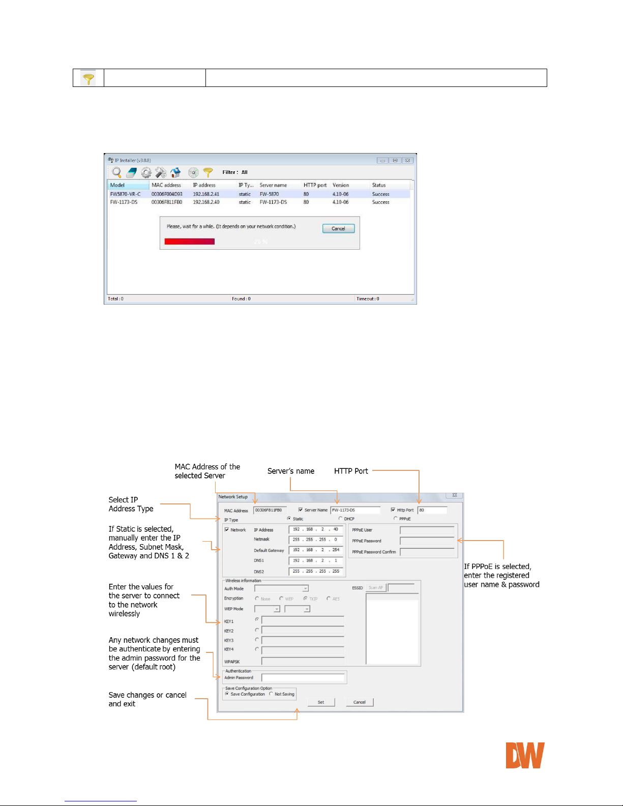
4.3.4. Manual Network Setup
Configuring the network settings of the Compressor can be done by performing any of the following
commands:
1. Right-click on the selected device and select Setup Product IP
2. Click the Manual IP Setup button on the main Toolbar
3. You can select multiple devices from the results list by holding the Ctrl button and clicking on
multiple devices in the list.
Setting up Network Configuration for a single product:
*
Page 20
DW-CP04 Manual
01Manual_CP04_05172013 20
Note: Wireless option currently not available in DW-CP04 models
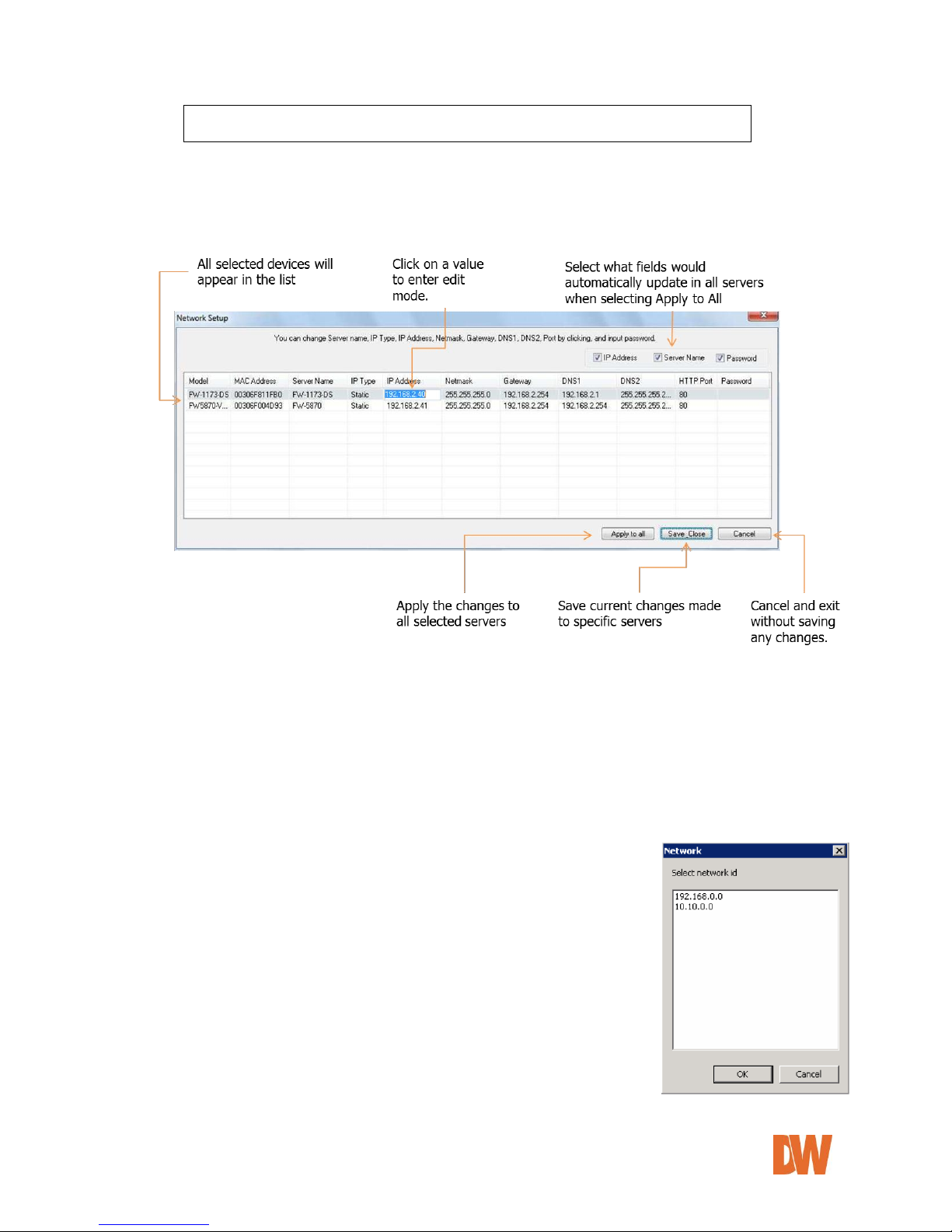
Setting up Network Configuration for multiple products:
Once multiple servers have been selected, press the manual IP Setup button.
All selected servers will appear in a list. You can modify the value of each changeable field by clicking it.
If you click Apply to all, the settings set to the first server will apply to all remaining devices. All will
have the same value for that parameter. In this case, each device’s Server name and IP Address field
will have +1 incremented value added to the original value.
For Password field, the entered information will be the same.
In using Apply to all, you can choose which field is affected. Put check marks only on the fields you
want to use this automatic action as below.
4.3.5. Automatic Network Setup
Before the system can automatically setup the server’s network settings,
select the IP type you would like for the device. Choose from the available
options: Static, DHCP, or PPPoE.
In this setup mode, the IP Installer program will check your local network
and assigns available IP addresses to the IP devices.
If the software detects that the network has more than one IP address
classes, a confirmation window will be displayed. Chose the proper IP
address you wish to assign your device as press ‘OK’.
Figure 1Double Network IP Warning
Page 21
DW-CP04 Manual
01Manual_CP04_05172013 21
5. Compressor’s Web Viewer
To open the Compressor’s web viewer via the IP Installer software, select one of the following options:
1. Double-click the server’s name in the results list
2. Right-click on the server’s name and select ‘Go Product Homepage’
You may be asked to install an ActiveX package. Accept all installations in order to connect to the
Compressor and view proper video over the web interface.
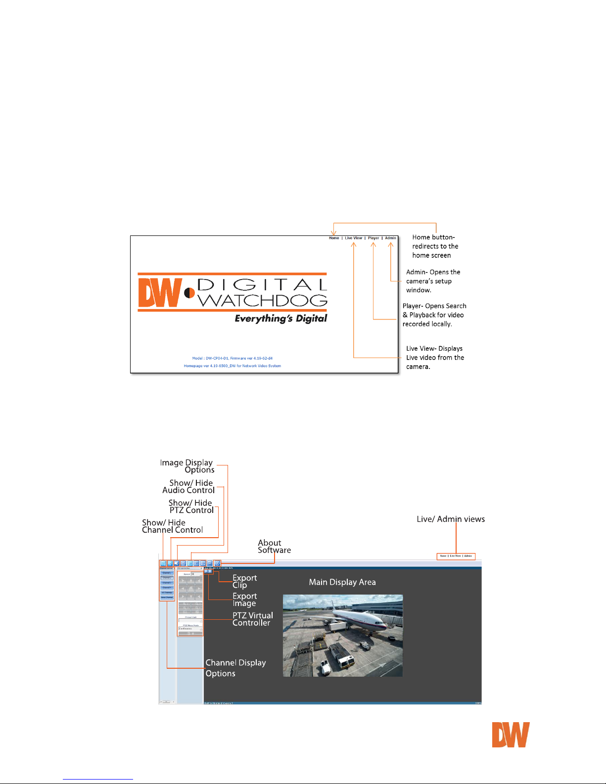
After connecting to a Compressor server on the web browser, you’ll find the web page as shown below.
The rightmost item of the menu is Admin, where you can set up the most of features in the Compressor
Server you’re connecting to.
5.1. Entering Live View
Click on ‘Live View’ to view the Compressor’s live display window. The image below will appear.
Use the controllers on the left side of the screen to change the view from single to multiple channel display,
run the virtual PTZ controller, and adjust the image display ratio.
Page 22

DW-CP04 Manual
01Manual_CP04_05172013 22
5.1.1. Single-Mode View
The Live Viewer will automatically open in single channel view, displaying Channel 1 by default. The screen
will display the camera’s module name, at the bottom green bar, and the date and time on the top green bar.
Channel 1 – Display or hide live view from Channel 1.
Channel 2 – Display or hide live view from Channel 2.
Channel 3 – Display or hide live view from Channel 3.
Channel 4 – Display or hide live view from Channel 4.
All Channel – Display live view from all channels.
None Channel – Hide live view from all channels.
5.1.2. Multi-Mode View
To view multiple channels, use the Channel control bar on the left side of the screen. Select which channels
you would like to add to the current view. Channels that are currently being displayed will be selected. Each
camera will have a blue bar at the top and bottom of the display, indicating the camera’s name and date &
time, respectively. Selected camera will be highlighted in a green bar at the top and bottom of the display.
5.1.3. Image Snapshot
You can take a quick screen shot of each of the Compressor’s channels to save for your records. To take an
image:
1. Press the button at the top left corner of the channel’s display. A new window will open with the
default directory to save the file. If necessary, select a different directory for the file.
2. The file’s name by default will be the date, time, and camera name.
3. All images will be saved as .bmp file. Press Save to save the file, or cancel to exit without saving.
5.1.4. Image Clip
You can take a quick video clip of a single channel to save for your records. Video clip files are available
in .avi format and can be up to 10 minutes. To record a short clip:
1. Press the button at the top left corner of the channel’s display to start recording. AVI REC will
appear in red at the top right-hand corner of the channel.
2. Press the again to indicate the end of the video recording.
3. A new window will open with the default directory to save the file. If necessary, select a different
directory for the file. The file’s name will be the date, time, and camera name. If necessary, change
the file’s name.
4. When you playback recorded view, time stamp will be displayed on the top left-hand corner.
Page 23

DW-CP04 Manual
01Manual_CP04_05172013 23
5.1.5. Instant Recording
Your Compressor is equipped with a built-in SD Card, allowing the Compressor to record video locally to the
micro card. The recorded video can be viewed by Instant Playback feature (See section 5.1.6 for more
information) or by running Smart-Player program. The Compressor supports up to one (1) minute of instant
recording to the SD Card, after that it will automatically stop instant recording. To record instant video to the
SD Card:
1. Press the button at the top left corner of the channel’s display to start recording. REC will
appear in red at the top right-hand corner of the channel.
2. Press the again to indicate the end of the video recording.
5.1.6. Instant Playback
Your Compressor is equipped with a built-in SD Card, allowing the Compressor to record video locally to the
micro card. The recorded video can be viewed by Instant Playback feature (See section 5.1.6 for more
information) or by running Smart-Player program. To view instant video recorded to the SD Card:
1. Press the button at the top left corner of the channel’s display to start recording.
2. The window below will appear.
3. Use the playback buttons to forward and playback video, play, pause, or select the playback speed.
5.1.7. Extended Features
Right-clicking on live video on any of the channels will open the extended features
options.
Pause- when selected, live video will freeze. Press the Pause button again to
unfreeze the image.
FPS- controls the frames-per-second that the Compressor is streaming. This
option is available only when the channel’s stream is set to MJPEG codec. Select:
1FPS, 2FPS, 5FPS, 10FPS, 15FPS, or fastest, based on current bandwidth
capabilities.
Flip- you can make mirrored (horizontal) or flipped (vertical) image from the original
Mute Audio- when audio output is enabled on a channel, select to mute the audio.
DO1- Click on DO1 to control alarm outputs connected to the Compressor.
Navigation- when selected, a small window of the full channel display will appear at the top right-hand corner
of the screen while in digital zoom mode.
Time Stamp- when selected, a screen shot of the selected channel will be automatically saved as .bmp file.
You can select the directory where the file will be saved, and alter the file’s name. The image will include
detailed time stamp at the top left corner of the image.
[Set the Beginning time for playback]
[Set Playback Speed]
[Begin Searching Data]
[Start Playback]
[Reverse Playback]
[1 Frame Fast Forward]
[1 Frame Reverse Playback]
[Pause]
[Stop]
Page 24

DW-CP04 Manual
01Manual_CP04_05172013 24
5.1.8. Video Control
The Compressor allows you to control the video display from each channel using the following buttons. These
buttons are located at the tool bar at the top of the live viewer.
The video will be displayed at its original resolution. Use the scroll wheel of the mouse to digitally
zoom in and out. Pressing the scroll wheel button of the mouse (scroll wheel) will display video in
actual size. You can also use +, -, / keys for zoom-in, zoom-out, and return to original size.
If video is smaller than the screen, it is displayed in the original size. If video is larger than the
screen, it is adjusted to fit to the screen with the same aspect ratio. Zooming is not supported in this
mode.
Video will be resized to fill the entire screen. Zooming is not supported in this mode.
5.1.9. Audio Control
The Compressor supports two-way audio communications between the Compressor and the
web viewer client. See 8.3 Camera & Motion for information on how to setup the audio.
To receive an audio transmitted from the Compressor, select a proper channel on SmartViewer and you will be able to hear the audio via the web viewer.
To send audio from the web viewer to the Compressor, connect a proper audio output
device to your computer.
If an audio device is properly connected to your computer, the 'Disconnected' icon will
change to 'Connected'.
Press 'connect' to speak and use the volume bars to adjust the audio in and out options.
5.1.10. PTZ Control
See the admin section on how to properly setup a PTZ camera with the
Compressor. Select the channel with a PTZ camera, and make sure the
virtual PTZ controllers are enabled. Use the different buttons and
controllers as explained below to move, zoom, and control your camera.
1. Speed- Adjust the rate of camera motion. It can be between 1 and
16, and higher number is faster.
2. PTZ Controllers- control the camera using the 8 directional arrows.
3. Zoom- Adjust the Zoom using the +/- buttons to zoom in and out,
respectively.
4. Focus- Adjust the focus using the +/- buttons to focus near and far,
respectively.
5. Auto Pan- for cameras that support the Auto Pan feature, start and
stop previously set auto pan.
6. Present Call- move the camera automatically to the preset position
as it is configured in the PTZ control on the Compressor.
7. Move the camera in 2 different modes: Step and Continuous modes.
a. Step mode: Camera moves as much as previously defined
each time. This mode is effective for remote cameras with
slow network condition.
b. Continuous mode: Camera keeps moving while direction control buttons is pressed. This
mode is effective for local camera with fast responsiveness.
8. Advanced Options- press to expand the PTZ control window and view the options below:
a. Group- Assign groups and run/ stop groups.
b. Tour- Setup and run tours.
c. Power- turn the camera ON and OFF.
d. Output- control the camera’s alarm output.
e. Input 1 + 2- control up to 2 sensor inputs connected to the camera.
Page 25

DW-CP04 Manual
01Manual_CP04_05172013 25
5.2. Entering the Smart Player
5.2.1. Smart Player’s Main Screen
Use the Player option to search the Compressor’s playback, recorded to the SD Card. Please note that the
cameras must be set to record for the playback and search options to be enabled.
Server Control Bar- displays the camera information in a tree hierarchy. You can compose a new group by
drag & drop of servers, modules, and cameras of server into the group.
Group Control Bar- Users can make new groups and compose groups by dragging & dropping servers,
modules, and cameras.
Playback Control Bar- Control the playback video’s forward/reverse play, previous frame, next frame, pause,
stop, playback speed, and playback position.
Control Tool Bar- Change search mode between day, condition, and data, backup video, take a screen shot,
print a screen shot, adjust the image’s display ratio, enable/ disable audio, watermark, and get information
about the smart player.
Search Control Bar- Search condition (day, condition, and data) can be refined in this bar.
Display Screen- displays selected cameras’ playback video.
5.2.2. Searching Video
The Compressor’s smart player supports two search options: Day Search and Condition Search. These
options are depicted in the player’s tool bar as individual buttons located at the top left-hand corner of the
screen.
To select one, make sure the server is properly connected in playback mode, and that there is at least one
group setup for search and playback.
Day Search:
In day search mode, you can choose a single day and time frame to search.
1. Make sure the Day Search button at the tool bar is enabled.
2. Go to the Search control bar. Use the calendar on the left-side to select a day. Days with recorded
video available will be marked in Red. Today’s date will be marked in white.
3. To select a day, click on the day’s number in the calendar. You can also press the Go to time
position button to manually enter a specific hour and minute and press the Search button.
4. When a day from the calendar is selected, a time map will be displayed on the search control bar,
displaying 24 hours of the selected day. Time with recorded video will be marked using a green bar
for each channel. Use the large arrows on each side of the time bar to view all 24 hours of the
selected day.
Page 26

DW-CP04 Manual
01Manual_CP04_05172013 26
5. Using the red time line, move to the desired time you would like to view playback from. Video will
automatically start playing according to the position of the red time line in the time bar.
Condition Search:
Condition search allows you to search for video by motion detection and sensor activation.
To use Condition search:
1. Make sure the Condition Search button at the tool bar is enabled.
2. Go to the Condition search bar at the bottom of the page. If you want, set a time limit to the search
by checking the Time checkbox and selecting the start and end time.
3. Click Search.
4. Search results will be displayed in a table format, displaying the camera’s name, result number, event
start time, and event end time.
5. Click Advanced for additional search settings:
a. Select whether to search a single camera or the entire group. Press Add Condition.
b. If you want to search for specific events, check the box next to Event.
c. Select which cameras to search for motion detection. Press Add Condition.
d. Select which cameras to search for Sensor activation. Press Add Condition.
e. Press Search to search according to the new set conditions.
6. To view playback video, double- click on any of the search results to automatically start
corresponding playback.
5.2.3. Extra Features
Window Control- adjust the location and visibility of the different windows available in playback mode. Select
to show/ hide: Server window, Group window, Play window, Search windows, Log windows, or go to default
layout.
Recording Period- Check the starting/ ending date of recording video from up to 1 year ago.
Backup- you can backup specific video and store them locally or on a removable HDD. Backup files can be
saved as .idx (can be played on the Compressor’s player) or .avi.
To backup video:
1. Click the Backup button. A new window will appear
2. Select which cameras to include in the backup.
3. Select the start and end time for the backup period.
4. Select the backup file type (.idx or .avi).
5. Select the directory path where you would like to save the backup file.
6. Select the frame-rate for the video that is being backed up. The higher the frame-rate is, the larger
the backup file will be.
7. Press the OK button.
8. The backup status bar will appear, indicating the progress of the backup.
Note: AVI files support single-channel backup. IDX file supports multiple cameras.
Note: Adjusting the frame-rate is for AVI file only. When an original file was recorded
at 10fps, if backup frame rate is set to 30fps, 3-second length of original video
will be crammed into the 1-second length of the backup video to make it 30
fps. Backup video then will play back 3 times faster than the original video.
Note: For M-JPEG, fps is automatically set.
Page 27

DW-CP04 Manual
01Manual_CP04_05172013 27
Snapshot- Choose the camera currently being played or paused, click Snapshot button. Then a snapshot file
will be saved in a designated path. Image will be saved with time stamp at the top left-hand corner of the
image.
Print- Choose the camera currently being played or paused, then click Print button. Then the image of the
selected camera will be printed out.
Ratio Display- adjust the display ratio for your cameras.
Select Original to view the camera in its original size, regardless of the window’s display size.
Select Ratio to change the camera’s image to fit the screen, while maintaining its aspect ratio.
Select Stretch to stretch the camera’s image across the screen to fit the window’s display size,
regardless of the camera’s original display size or ratio.
Full Screen- view the display area in full screen mode.
Audio- make sure the audio is properly setup in the camera and is enabled in the camera’s recording
schedule. Press the Audio button in the tool bar to adjust the volume of the playback audio.
Watermark- Watermarking protects the backup file from forgery of video data. Watermarking is supported
only when a single channel is being played back. Video compression should be set to MPEG-4 to support
watermarking. If watermark checkup is set to Enable, Smart-Player program will inform you by text whether
the video contains watermark and the whether the video is proper MPEG-4 file which supports it.
Information- view the smart player’s current version and additional information.
5.3. Entering Admin Menu
Click “Admin” item of the menu, then you’ll see a login window. In the login window, enter “root” for both ID
and password as they are the factory defaults. Press Enter key or click “OK” button. Once logged in, you
can change the password to a new one.
The Admin Menu will be displayed as shown below. This will guide you to the top level menu items, which
are Quick, System, Network, Device, Advanced, Recording and Utilities. Clicking any of these top level
menu items will display submenu items and brief descriptions.
Page 28

DW-CP04 Manual
01Manual_CP04_05172013 28
5.4. Admin Menu Structure
The following table shows the hierarchy of the Admin menu structure that we’re going to deal with in this
manual.
Category
Main Menu
Level 1 Sub-Menu
Level 2 Sub-Menu
Quick Configuration
Server Name Setup
n/a
n/a
Local Date & Time
Configuration
Network Configuration
IP-CCTV DNS™ Setup
Recording Configuration
Finish
System
configuration
Server Name
n/a
n/a
Date & Time
Admin. Password
Access Control
User Registration
Network
Configuration
Network Configuration
n/a
n/a
Network Ports
Bandwidth Control
View Network Status
Network Status Notify
IP-CCTV DNS™
Port Forwarding & UPnP
RTP/RTSP
SNMP
Device Configuration
Serial Ports
Serial Input Mode
n/a
Serial Output Mode
n/a
Transparent Mode
PTZ Mode
Privacy Zone
Camera 1~4
n/a
Camera & Motion
Camera 1~4
n/a
DI/DO
n/a
n/a
DI Status/DO Control
n/a
n/a
Advanced
Configuration
Advanced Services
E-mail
Camera 1~4
Condition 1~3
FTP(Buffered)
FTP(Periodic)
Sensor Notification
Input 1~4
Condition 1~3
Alarm Output
Output 1~4
Condition 1~3
Recording
Configuration
SD Configuration
SD Status & Format
n/a
SD Information
n/a
Page 29

DW-CP04 Manual
01Manual_CP04_05172013 29
Recording Configuration
Built-in Module 0
Camera 1~4
Recording Profile
n/a
n/a
Recording Mode
SD Status Report
Clear Recording Configuration
Delete Recorded Data
Utilities
System Log
n/a
n/a
Save Configuration
Reboot
Factory Default
System Update
6. Quick Configuration
The first time you connect to the DW-CP04, it is recommended to run the quick configuration wizard. This will
guide you through setting up all the main options for the proper operation of your new Compressor.
6.1. Step-1 Server Name Setup
Click Server Name in the Quick Configuration menu to view the server’s model name, server name, MAC
address, and current firmware and web viewer versions. In this window, you can adjust the server’s name.
Click ‘Apply’ to save any changes, or ‘Back’ to return to the previous step. See the section 7.1 Server Name
Setup for more information.
6.2. Step-2 Local Date & Time Configuration
Click Date & Time on System Configuration menu, then Local Date & Time Configuration window will be
displayed. If necessary, you can manually adjust the Compressor’s date and time, change the time zone or
enable an NTP server connection. Click ‘Apply’ to save any changes, ‘Refresh’ to make sure the changes
have been applied, or ‘Back’ to return to the previous step. See the section 7.2 Local Date & Time
Configuration for more information.
6.3. Step-3 Network Configuration
The Compressor’s Network Configuration can be done from the IP Installer software, or locally at the server’s
web viewer. To adjust the internet settings, select the connection type (Static, DHPC, or PPPoE). If static IP
is selected, enter the necessary information such as IP address, subnet mask, gateway, DNS 1 and DNS 2.
Click ‘Apply’ to save any changes, ‘Refresh’ to make sure the changes have been applied, or ‘Back’ to return
to the previous step. See the section 8.1 Network Configuration for more information.
Page 30

DW-CP04 Manual
01Manual_CP04_05172013 30
6.4. Step-4 IP-CCTV DNS™ Setup
The Compressor can be assigned a Dynamic Domain Name Server [DDNS]. Using a DDNS address is
recommended when a DHCP address is used. It allows you to connect to the Compressor without the worry
of the changing IP address. Click ‘Apply’ to save any changes, or ‘Back’ to return to the previous step. See
the section 8.6 IP-CCTV DNS™ Setup for more information.
6.5. Step-5 Recording Configuration
Each camera can be configured for recording option in this section. See the section 11.2 Recording
configuration for more information.
6.6. Finish
You need to save all the changes once the quick configuration wizard is complete. The changes made to the
Compressor Server will be permanent by this step. Click Finish on Quick Configuration menu. Click Back
to return to the previous set to adjust any of the settings.
7. System Configuration
When you click on System Configuration item on Admin Menu, the following sub menu will be displayed.
7.1. Server Name Setup
Click Server Name, then the following will be displayed and you will find out the system information such as
model name of the Compressor Server, Server name, MAC address (Serial Number), Firmware version and
Web image version.
Page 31

DW-CP04 Manual
01Manual_CP04_05172013 31
As an administrator, you can change the server’s name. To change the server’s name, enter a new server
name in the Server Name filed. You may use up to 21 alphanumeric or up to 10 Unicode characters. Tab or
any other special characters are not allowed. Click “Apply” to save the settings immediately.
7.2. Date & Time
Click Date & Time, then the following options will be displayed. Use this setup menu to set up the local date
& time, time zone, and setup NTP server address and time. Please note that the Time is in 24:00 hours
format. For example, 3PM should be entered as 15:00:00. Click “Apply” to save the settings immediately.
7.3. Administrator Password
To change the password for the administrator, click Admin Password on System Configuration menu.
Default ID for admin account is fixed as “root” and not allowed to change. In Old Password field, enter the
current password. In both New Password and Confirm Password fields, enter the same new password.
The password must be between 4 and 23 alphanumeric letters. Click Apply to save.
Page 32

DW-CP04 Manual
01Manual_CP04_05172013 32
Because you have replaced the password with a new one, the existing network connection made with old
password will be terminated. You will have to reconnect to the Compressor server using the new password.
7.4. Access Control
Click Access Control on System Configuration menu. The following windows will be displayed. From the
Access Permission window, select either one you would like to use. Click Apply button to save the change.
Full Access: Any user can access the server and use all the features without limit.
Limited Access: Only registered users can access the server and have limited privileges.
7.5. User Registration
Use this setup menu to add, modify or delete users and their access to the Compressor server.
7.5.1. Add
To add a user, click User Registration on System Configuration menu. Next, select Add, then the
User Registration (Add) selection screen will be displayed. When Add is selected, you can add
users and define their passwords, names, and access permission levels.
Enter a user ID, which must consist of up to 23 alphanumeric characters. In both Password and
Confirm Password fields, enter the identical password. The password must be between 4 and 23
alphanumeric characters. In Name filed, enter the user’s name that must be up to 31 alphanumeric
or 15 Unicode characters. Select one of the four items from System Resource Access Permission,
which defines the permission level for registered users to the Compressor server.
Page 33

DW-CP04 Manual
01Manual_CP04_05172013 33
All Channels Access: User can use all the features except for the configuration options in the
Admin Page.
General Access (only live viewing access): User can use only Live View features.
No Access: User is not permitted of any of the features.
Selective Access: User is allowed to use only the features selected from the table below.
Check the Enable box next to each field to setup the specific features for each user.
A. VS Module ID: The registered user can select VS Modules that are available.
(VS Module is a network device that has been registered in Compressor Server. The
Compressor has a default VS Module- Built-in Module 0)
B. Camera No.: Among the cameras of VS Module, select one to set up. (between 1 and 4,
or all)
C. Alarm Control: Determine if Alarm control is to be allowed.
D. PTZ Control: Determine if PTZ Control is to be allowed.
E. Audio Control: Determine if Audio Control is to be allowed.
Click Apply button to add the user.
7.5.2. Edit
To edit a user account, select Edit. In this part, you can modify the existing user’s name, password,
and access permission. User ID is not allowed to change. Once selecting a user ID for edit, the usage
is the same as in Add section.
To see existing users, click Select User ID, and select a user to be edited from the drop-down menu.
Then change the password, name or access permission, and click Apply button to save the setting.
Setup of Access Permission can be done the same way as in Add section.
Note: To activate your setting at this 'User Registration' menu,
- Click above "Apply" button.
- Go to 'System Configuration' -> 'Access Control'.
- Select "Limited Access".
- Click "Apply" button at the 'Access Control' page.
Otherwise, 'User Registration' will not be activated.
Page 34

DW-CP04 Manual
01Manual_CP04_05172013 34
7.5.3. Delete
To delete an existing user, select Delete. From the list of the users, select a user’s ID you want to
delete. Then, click Delete button to confirm the deletion.
8. Network Configuration
Configuration of the network settings of the Compressor may vary depending on how an IP address is
assigned in Ethernet-based environment.
To make a connection to the Internet, it is required to figure out the type of the Internet service you’re using.
Depending on the service type, the network configuration can be in any of Static IP, DHCP Client or PPPOE.
Page 35

DW-CP04 Manual
01Manual_CP04_05172013 35
8.1. Network Configuration
8.1.1. Static IP Configuration
Select the Network Configuration sub-category to view the available network settings.
For static IP, select static IP and input the corresponding values for IP address, Net-Mask,
Gateway, DNS1, DNS2 and click “Apply” to save. Press “Back” to cancel all changes. Press
“Refresh” to load last saved values.
8.1.2. DHCP Client Configuration
For DHCP, DHCP server must exist in the network environment. Select DHCP Client from Network
Configuration, click “Apply”. If DHCP is selected, the server will automatically assign the network
settings based on the current network’s requirements.
Page 36

DW-CP04 Manual
01Manual_CP04_05172013 36
8.1.3. PPPoE Configuration
For PPPoE connection, enter the username and password acquired from your Internet Service Provider
[ISP]. Contact your ISP or your Network Administrator for additional information. Click “Apply” to save or
“Back” to cancel.
8.2. Network Ports
In this configuration page, you can setup the HTTP port for the Compressor Server to communicate with the
Client PC. HTTP Port is the network port that is used when a Client PC connects to the Compressor Server’s
Web page. It can be assigned between 80 and 65535 and the default value is 80.
8.3. Bandwidth Control
Bandwidth control settings allow you to limit the maximum network traffic used by the Compressor. If it is
enabled, enter the bandwidth limit in Kbps. The maximum data size transferred from the Compressor will not
exceed bandwidth limit set. If transferred data is exceeded, part of data will be randomly lost.
If multiple users try to access the Compressor when a bandwidth control is in place, users connected to the
Compressor will share the limited network bandwidth.
Page 37

DW-CP04 Manual
01Manual_CP04_05172013 37
8.4. View Network Status
This menu shows network status of the Compressor’s Network settings and status, including IP address
settings, Modem status, and PPPoE status (if applicable). Use this link to make sure that any changes made
to the Compressor’s network settings are saved and are properly functioning.
Note: IF the HTTP port number is changed to other value than default (80), make sure the
new HTTP port number goes together with the Compressor’s Internet address. For example,
Compressor’s IP address is 196.168.1.00 and set the HTTP port to 8080, you will have to
enter http://192.168.1.100:8080 to connect to the server
Page 38

DW-CP04 Manual
01Manual_CP04_05172013 38
8.5. Network Status Notification
The Network Status Notifications menu allows you to setup e-mail notifications when the IP address of the
Compressor changes. This function is available when the Compressor is set to DHCP or PPPoE only. The
following events will trigger an e-mail notification:
When it is set to Dynamic IP on Network Configuration menu, and the Compressor server has been given a
new dynamic IP address and connected to the network.
Or,
When it is set to PPP Client on WAN-Modem menu, and the Compressor server has been connected to the
network with ISP or PPP server.
1. Select ‘Enable’ to use the feature.
2. Enter the address of the SMTP server which is needed for email service. If your SMTP server
requires a user ID and a password for authentication, you will have to get them from your ISP or
network admin. Enter the ID and password.
3. In Sender field, enter your email address or other meaningful words that will show the message
was sent from the Compressor server as a notification.
4. Enter the email addresses of the recipients in the Recipient fields. You can send network e-mail
notifications to up to three (3) e-mail accounts.
5. In the User-Defined Message box, enter a message to explain why the message was sent.
6. Click “Apply” to save settings.
.
Mail Notification
Enable: Send email
Disable: Do not send email
SMTP Server
SMTP Server address for email service
Authentication Login
Enable: user ID and password are required for SMTP
server
Disable: user ID and password are not required
User ID
User ID for SMTP server
Password
Password for SMTP server
Sender
Email address of Sender
1st / 2nd / 3rd Recipient
Email Addresses of the Recipients (up to 3 accounts)
User Defined Message
Message to be included in the Notification email
Page 39

DW-CP04 Manual
01Manual_CP04_05172013 39
8.6. IP-CCTV DNS™ Setup
IP- CCTV DNS service provides a static & public domain name to help users access Compressor products
even though their IP address is changed or they are used in local network. For proper function of IP-CCTV
DNS service, products should be accessible through internet.
To use IP-CCTV DNS, users must create an ID from IP-CCTV DNS™ server (http://www.ipcctvdns.com) and
register the Compressor using its MAC address and Product Key. This information can be found under the
IP-CCTV DNS™ Setup menu under the Network Configurations menu. Enable service and click Apply.
1. Go to the IP-CCTV DNS Setup menu
2. Make sure the Enable button is selected on the Compressor’s IP-CCTVDNS setup page.
3. Click the Go button next to the website address. This will take you to the IPcctvDNS website.
4. Click Sign-up
5. Read and select whether to agree or not to the terms and service agreement.
6. Enter your e-mail address in the ID section and press the check button. The website will notify
you if the e-mail is available to use as an ID.
7. Entered a desired password and confirm it.
8. Enter your contact information as required, including name, company name, phones, and
address. The country location will determine the location of the server used for your
Compressor’s DDNS. Chose the closest city to you available from the list.
9. Click ‘save’, your user will be created and the website will prompt you to the main page for login.
10. Enter your new user ID and password and click Login.
11. Go to “Product Registration”
12. Enter a name to associate with the Compressor.
13. Enter the MAC address and Product-Key of your Compressor and click apply. The product will
be added to your product list.
14. Your Compressor’s DDNS address will be the DDNS Host Name as it appears in the Product
List section of the website. For example: http://hostname.ipcctvdns.com:externalport.
15. By default, the hostname given to your Compressor will be fw841932. To change the host name,
click on the ‘Detailed Information’ button at the top right-hand corner of the Product List page.
16. Select ‘Edit’ and enter a new host name.
17. Click ‘Apply’ to save.
NOTE: Remember that additional settings such as Port Forwarding are necessary to complete the DDNS
setup for the Compressor. See section 8.7 Port Forwarding & UPnP for more information.
Page 40

DW-CP04 Manual
01Manual_CP04_05172013 40
8.7. Port Forwarding & UPnP
UPnP (Universal Plug and Play) is a kind of network protocol to help users to find and configure network
products in same local network area. Port forwarding assigns a certain network port in your router to a
network product for proper access from outside the Local Area Network. Generally, port forwarding can be
configured from the network router.
UPnP port forwarding is done by finding an available network port, assigning it to the Compressor and reporting the overall network configuration of the Compressor using the IP-CCTV DNS™ server setup in the
previous menu. Users have to register the products to IP-CCTV DNS™ server and IP-CCTV DNS™ service
should be enabled. See 8.6 IP-CCTV DNS Setup for additional information.
There are 3 options in UPNP Port Forwarding.
Manual: User Assigned Port is used when users can access network router (hub) and manually
assign available network port to Compressor. In this case, after you manually opened the ports in your
router select this option and enter the port you assigned to the Compressor.
UPnP: User Assigned Port is used when users want Compressor products to configure port
forwarding menu of network hub with user-assigned network port. If it fails, try to change userassigned port manually.
UPnP: Auto Selected Port is used to let the Compressor auto set the entire network configuration
automatically.
Please notice that network router should support UPnP Port Forwarding and there is a limit for
maximum UPnP devices. If it is properly configured, results will be appeared under UPnP status.
Page 41

DW-CP04 Manual
01Manual_CP04_05172013 41
8.8. RTP/RTSP
RTSP (Real-Time Streaming Protocol) is a protocol used to transfer video and audio streams over the
network. Any application supporting Standard RTSP can be used for the Compressor server. Quick Time
Player or VLC program can be used, but it may not be supported in an environment within a firewall. There
are two types of usages; one for Unicast address condition and the other for Multicast address condition.
Unicast Address:
Use “rtsp://network video server ip address/cam0_0”. For multiple channels, use cam0_x, x (0~3). If there
are multiple modules, use camx_0 x (0 ~ 3).
Multicast Address:
Use “rtsp://network video server ip address/mcam0_0”. For multiple channels, use cam0_x, x (0~3). If
there are multiple modules, use camx_0 x (0 ~ 3).
Service
Enable: Start RTSP service
Disable: Stop RTSP service
RTSP Port
In normal case, use default port number 554 to connect to RTSP service.
If not using port 554, enter the port number you want to use.
e.g.) port number 445==> rtsp:// network video server ip
address:445/cam0_0
RTP Start Port
The starting number of the port for video transfer. Each time video
transfer connection is made, the port number also increases.
Multicast
Address
Address for multicast video transfer.
The multicast address 0.0.0.0 is for stopping multicast.
Multicast Port
Port number for viewing the video with a multicast address
NOTE: To use ONVIF protocol, RTP/RTSP must be enabled.
Page 42

DW-CP04 Manual
01Manual_CP04_05172013 42
8.9. SNMP Setup
SNMP (Simple Network Management Protocol) is a protocol used to monitor and configure network status of
a network device. SNMP V1 and V2 are supported over MIB2 standard.
SNMP Trap can function when SNMP V1/V2 is enabled.
SNMP V1/V2
Enable: Start SNMP service
Disable: Stop SNMP service
Trap
Enable: Start SNMP Trap service
Disable: Stop SNMP Trap service
Destination IP
Address
IP Address to receive SNMP Trap messages.
Trap Community
Key value used in SNMP Trap e.g.) public
Available Traps
Type of SNMP Trap message
1. Cold Start : When SNMP starts
2. Authentication Failure : When key value of SNMP query is wrong
Page 43

DW-CP04 Manual
01Manual_CP04_05172013 43
8. Device Configuration
The Device Configuration menu options allow you to configure all the settings relevant to all external devices
connected to the Compressor such as cameras, Input / Output, and Alarm control.
8.1. Serial Ports Configuration
There are two serial ports configurable in the system, COM and AUX. COM port is primarily used for console,
and AUX port is used for PTZ control. However, both can be used for other purposes when necessary.
8.1.1. Serial Input Mode
When serial ports are set in Serial Input Mode, the Compressor can be triggered by the external
sensors to send images from the camera by email, or to an FTP server. It can also activate Alarm
Output by input from sensors inputs. To configure, click Serial Ports on Device Configuration. In
COM Port or AUX Port, select Serial Input and click Apply button to apply the change. The system
will reboot then.
Page 44

DW-CP04 Manual
01Manual_CP04_05172013 44
After rebooting, open the Serial Ports window in Device Configuration menu again. Select the
Serial Input Mode.
Current Port: This shows the name of the port currently configured.
Current Protocol: This shows the protocol currently being used. (RS-232 Only).
Serial Input Model: Select the sensor’s model number you want to use from the drop-
down menu.
The following example is when a speed sensor, AGILIS-HE820-SINGAPORE, is selected.
Upper Limit: The highest value in the range to assign
Lower Limit: The lowest value in the range to assign
Initial String Length: The length of initial string from sensor
Initial String Data: The initial string from sensor
(Speed) Delay: select Enable if sensor input needs delay
Internal process delay: The amount of delay for sensor input
Page 45

DW-CP04 Manual
01Manual_CP04_05172013 45
Sensor Aiming Position: The position for sensor to aim
Camera Aiming Position: The position for camera to aim
Add Vehicle length to calculate delay time: The length of vehicle for applying delay time
8.1.2. Serial Output Mode
Using Serial Output Mode, you can send commands from the Compressor to control PTZ devices,
Multiplexer, Access control box, X10 Protocol, z256 protocol. For external devices control, the
Compressor supports RS-232 or RS-485 communication.
Once an external device is properly connected to the Compressor for communication, select the
protocol, baudrate, data bit, stop bi, parity bit, and transmission mode.
Click ‘Apply’ to save, or ‘Back’ to cancel.
8.1.3. Transparent Mode
When there are two or more Compressors on the same network, they can act like a transparent
interface between two different UART devices, allowing the communication between the UART
devices is made transparently without a flaw.
Page 46

DW-CP04 Manual
01Manual_CP04_05172013 46
Line Mode: The type of communication protocol
Baud Rate: Data transfer rate
Data Bit: The number of bits in data
Stop Bit: The number of stop bit
Parity Bit: Parity bit characteristic
Network Protocol: The type of protocol used to send data
Peer IP: IP address of other Compressor server
Network Port: Network port number of the server
Data Start Pattern: Data start pattern (Not used if unchecked)
Data Size: Data size in single transfer (Not used if unchecked)
8.1.4. PTZ Mode
With the PTZ camera’s RS-485 cable wired to the Compressor’s COM or AUX port, select the proper
PTZ model in PTZ Mode Configuration screen, and then click Apply to save the change.
Select the appropriate protocol from the drop-down menu. Please note that when a protocol is
selected, the default baudrate value will automatically be entered. You can change that value at any
time. Consult your camera’s manual for additional information on the proper protocol, baudrate and
address you should use.
Page 47

DW-CP04 Manual
01Manual_CP04_05172013 47
Base Address should match the address of the PTZ camera or the receiver used here. (Base
Address = PTZ Camera’s Base Address – 1).
Once the Base Address of the camera is entered, select the channel that is connected to PTZ
camera, and click ‘Save’.
If the PTZ camera supports advanced functions such as preset swings, presets, groups, and tours,
click Devices Configuration > Serial Ports > PTZ Mode > Camera 1 and click on the Preset &
Menu button. The video monitoring screen will appear as shown below.
Use the PTZ control to move the camera to a desired spot. Select the Preset number you’d like to
assign to it. Click Set button to save the preset values in the Preset number.
Mode: When Step is selected, the camera will move as much as pre-defined distance. When
Continuous is selected, it will keep moving as long as the button is being pressed.
Speed: In Step mode, different Speed value is different Step size. In Continuous mode, it is
different moving speed.
Click the Menu button to display the camera’s OSD to adjust the camera’s attributes. OSD setting
can be controlled by using the Up, Down, Left, Right arrow keys. After setting is finished, click Menu
button.
Page 48

DW-CP04 Manual
01Manual_CP04_05172013 48
8.2. Privacy Zone
Users can set up to two (2) privacy zones per camera to block certain parts of the screen. To set the
region:
1. Click Privacy Zone from Device Configuration category.
2. Select Camera 1~4. The selected camera’s display will appear.
3. Click New to create a new masking. A red square will appear in the center of the screen.
4. To change the size of the mask:
A. Click and hold any of the mask’s corners.
B. Move the corner away from the center of the mask to increase the size of the mask.
C. Move the corner towards the center of the mask to reduce the size of the mask.
5. To move the mask to a different position, click and hold the center of the mask. While clicking on
the mask, move it to the desired position.
6. Click Apply to save the changes, or Delete to remove the mask from the display area. Saved
masks will appear in green on the screen.
Camera1
Camera2
Camera3
Camera4
Page 49

DW-CP04 Manual
01Manual_CP04_05172013 49
8.3. Camera & Motion
This menu is used to set up the recording video format, data added to video data, encoding speed,
audio control, image resolution, video quality, motion detection, etc.
Click Camera & Motion on Device Configuration menu to open the configuration page as seen below:
Video with Flexible Extra System data: If Enabled, recorded video will contain Flexible
Extra Data from COM port.
Video with user defined message: If Enabled, recorded video will contain the user-defined
data. (Reserved Field)
Video with PPP status: If Enabled, recorded video will contain PPP connection status.
Video with camera name: If Enabled, recorded video will contain camera’s name.
Video with server name: If Enabled, recorded video will contain server’s name as defined by
the user.
Video with IP address: If Enabled, recorded video will contain the IP address of the server.
Audio: Select if Audio function is to be used (applies to Primary Stream only). DW-CP04
supports 2-way audio streaming by combining microphone input with video data. Users can listen
to the streamed audio on PC speakers.
Image Size: Select the resolution of each channel’s video
Frame Rate: Adjust the number of frames per second the channels are recording.
Encoding Standard: Select the compression method of each video, either MJPEG or H.264
format. Both streams cannot be set to MJPEG
o H.264: In this format, each frame data is related to other nearby frames. For this reason, it
provides much higher compression ratio than MJPEG and is adequate for video transfer.
However, if network condition is not very good and frames may drop, the video quality can
be relatively low.
o MJPEG: This format requires much higher network bandwidth than H.264 compression.
But because of its higher quality of still image, it is adequate for detailed reviewing of
stored video.
To save the setting, click Apply button.
Page 50

DW-CP04 Manual
01Manual_CP04_05172013 50
8.3.1. Camera Configuration
On the lower part of Camera & Motion Configuration menu, select a channel you want to configure.
Then, enter the detailed parameters of the camera selected here.
Camera Name: Enter the name of the channel in up to 21 alphanumeric or up to 10 Unicode characters.
Color Mode: Select if the image will be in Color or Gray
Hue: Set the color of image between -100 and 100
Saturation: Set the intensity of the image between -100 and 100
Contrast: Set the contrast of the image between -100 and 100
Brightness: Set the brightness of the image between -100 and 100
Rate Control Mode: Select from VBR or CBR mode.
Image Quality: Set the Image quality levels (Low Compression / Highest / High/Normal / Low / Lowest)
Image Quality Setup
If VBR [Variable Bit Rate] is selected:
Video frames are encoded with selected image quality and GOP. Encoded frames have different data size
from each other.
Image Quality: one of 6 quality levels (Low Compression / Highest / High/ Normal / Low / Lowest)
GOP Structure: Distance between I-Frames. That is filled with P-frames.
If CBR [Constant Bit Rate] is selected:
Video frames are encoded with selected image quality and GOP. Encoded frames have the same data size
as other frames. Due to the constant bit rate, it has better stable transmission performance.
Bit Rate Control: Total number of Bits encoded per second. The higher Bit Rate, the better image quality.
Bit-rate can be set between 32kbps and 12Mbps.
GOP: Distance between I-Frames. That is filled with P-frames.
Motion Detection: This decided whether the Motion Detection is to be used.
o If Enable is selected, you can set which part of the camera’s field of view will be set to
motion detection.
o A green grid will appear on the display, indicating that the entire field of view is set to motion
detection.
o Click on different parts of the field of view to turn the grid red, indicating no motion detection
is set for those areas.
Page 51

DW-CP04 Manual
01Manual_CP04_05172013 51
o After configuration is finished, click Apply button to save the setting.
o Default will reset the motion detection’s configuration back to factory default.
Motion Sensitivity: Use the sensitivity bar to adjust the camera’s sensitivity to motion. It can be
between –100 and 100 while 100 is the most sensitive.
8.4. DI/DO
Select DI/DO from Device Configuration menu to configure Sensor Input and Alarm Output. Select DI
Status/DO Control on Device Configuration menu to configure the behavior of those Input and Output ports.
8.4.1. DI/DO
There are 4 serial Input ports and 4 output ports in the DW-CP04. DI(Sensor Input)/DO(Alarm Output)
Setup:
Each Input and Output port can be assigned unique name respectively, so that you can easily
distinguish every Input and Output ports from others by those names.
DI/DO functionality can be set to either Normal Open or Normal Closed type as follows.
o Normal Open Type: Normal is OPEN, and goes CLOSED when triggered by an event.
o Normal Close Type: Normal is CLOSED, and goes OPEN when triggered by an event.
8.5. DI Status/DO Control
The DW-CP04 has 4 output ports that act like a push button. With DI (Sensor Input) Status, you can find out
the status of the Alarm Input port. If the checkbox of Check (On) is displayed as checked, the alarm is
activated. If not there are no check marks, the alarm is deactivated.
Page 52

DW-CP04 Manual
01Manual_CP04_05172013 52
9. Advanced Configuration
The Compressor can be configured to start and stop certain pre-defined services by scheduling, event, or
conditions. There are two types of advanced service, one is Buffered Service and the other is Periodic
Service. In Buffering Service, a series of images are continuously being stored in a buffer memory of server
for a certain period of time. When the server is triggered by an event or schedule, the images or alarm status
just before and after the event/schedule are reported to you by email or buffered FTP services.
9.1. Advanced Services
Total Pre-Alarm buffer size and buffering speed can be defined here.
Pre-Alarm Buffer Size: You can set the buffer size which will store the
images before event. The unit is in frame, and each channel can be
set with different values. The total number of frames for Pre-Alarm
Buffer and Post-Alarm Buffer is limited to 10 frames.
Pre-Alarm Speed: You can set the buffering speed. If it’s set to Fastest, the server will store
images as fast as it can. Each cannel can be set with different values.
9.1.1. E-mail Service Configuration
You can setup up to three (3) conditions where the DW-CP04 will send an e-mail notification to a
predefined account.
E-mail Server Setup
To setup the SMTP server for the e-mail notifications:
1. Go to Advanced Configuration > E-mail.
2. Enter the SMTP server’s address and port
(default is 25)
3. If authentication is necessary, enter the User ID
and Password of an e-mail account associated
with the DW-CP04.
4. Enter the sender’s information
5. Enter up to 4 lines of text that would be sent with
each e-mail notification.
Page 53

DW-CP04 Manual
01Manual_CP04_05172013 53
E-mail Service Setup for Each Channel
For each channel, the following items can be configured for email service: Condition, Post-Alarm,
Buffer Size, and Post-Alarm speed. The content of e-mail message and display style of DI value can
be configured as well.
After finishing setup, click ‘Save’ button to apply. If you don’t want to change, click ‘Back’ button.
Condition, Schedule & Event Configuration
If you click on a Condition link, the Advanced Service windows is displayed as shown below.
Alarm Service is activated only when the conditions in Advanced Services are met.
Item
Description
Service
This shows what service this condition is for.
Module ID
Module ID for current setup
Camera ID
Channel ID for current setup
Enable / Disable
Select Enable to use Condition, otherwise select Disable.
Always
This Condition applies all the time. (Schedule or Event is not usable)
Schedule Only
Use Week, Time, and Date in Condition parameter.
Event Only
It is activated only when any of the following events occurs.
(Sensor, Motion Detection, Camera Connection, Server Booting)
To save the setting, click ‘Save’ button. If you want to cancel it, click ‘Back’.
Page 54

DW-CP04 Manual
01Manual_CP04_05172013 54
9.1.2. FTP(Buffered)Service Configuration
Item
Description
Camera 1 - Camera 4
Select which channel to set up for FTP (Buffered).
Service
Select Enable to use the FTP (Buffered) service. Otherwise select Disable.
Server Address
FTP Server Address.
Base Directory Name
The directory in FTP server where the data will be uploaded.
(You should make the directory in the FTP server before using the service.)
Base File Name
The base file name of the data to be uploaded in FTP server.
User ID
Enter a User ID to log in to FTP server.
Password
Enter the Password for the user ID to log in to FTP server
FTP Control Port
Port number for FTP server (Normally 21 is used)
Date Description Mode
Select Date Display Style (e.g. 20090228)
Connection Mode
Select connection mode for FTP server
Server Name
If Directory Name is checked, new directory is created with server name.
If File Name is checked, new file is created with server name.
Weekday
If Directory Name is checked, new directory name is created with weekday.
If File Name is checked, new file name is created with weekday.
Month
If Directory Name is checked, new directory name is created with month.
If File Name is checked, new file name is created with month.
Day
If Directory Name is checked, new directory name is created with day.
If File Name is checked, new file name is created with day.
Hour
If Directory Name is checked, new directory name is created with hour.
If File Name is checked, new file name is created with hour.
Minute
If checked, new file name is created with minute.
Sec
If checked, new file name is created with second.
Sequence
If checked, new files are created starting from 0, with increment of 1.
Camera Number
If Directory Name is checked, new directory is created with camera
number.
If File Name is checked, new file is created with camera number.
Page 55

DW-CP04 Manual
01Manual_CP04_05172013 55
To create a directory with the options shown above, click Make Directory. After finishing the
configuration, click ‘Save’ button to apply the change and continue to the next page. Clicking ‘Back’
button will cancel the changes and go back to the previous page. (This service is available only in MJPEG
mode.)
FTP(Buffered) Service Configuration for each Camera
Item
Description
Condition 1 ~ Condition
3
Select a condition for FTP (Buffered) service to be activated. Up to 3
conditions can be set.
Pre-Alarm Buffer Size
The Buffer size assigned for Pre-Alarm.
Check Video buffer
Click this link to go to Advanced Services for video buffer setup.
Pre-Alarm Images
The number of image frames to store before Alarm.
Post-Alarm Images
The number of image frames to store after Alarm.
Pre-Alarm Speed
This field shows the speed of Pre-Alarm. Configuration can be done in
Advances Services page.
Post-Alarm Speed
Select the speed of Post-Alarm. Fastest is the highest value.
After finishing setup, click ‘Save’ button to apply. If you don’t want to change, click ‘Back’.
Page 56

DW-CP04 Manual
01Manual_CP04_05172013 56
9.1.3. FTP (Periodic) Service Configuration
FTP (Periodic) Service Configuration for each Camera
Item
Description
Condition 1 ~ Condition 3
Select a condition for FTP (Periodic) service to be activated. Up to 3
conditions can be set respectively.
Alarm Speed
Select the speed of images to send in FTP(Periodic) service
After finishing setup, click ‘Save’ button to apply. If you don’t want to change, click ‘Back’.
Page 57

DW-CP04 Manual
01Manual_CP04_05172013 57
9.1.4. Sensor Notification
Item
Description
Input 1 - Input 4
Select which input to set up for Sensor Notification Service
Service
Select Enable to use Sensor Notification.
Service Mode
Select network mode for CGI. Select: HTTP, TCP, or UDP.
Main IP address
Enter IP address to use in CGI or other functions
Aux1 ~ Aux 3 IP address
Enter 3 more addresses to use in CGI or other functions if needed.
Port
Enter port number for CGI or other functions. Default is 80.
CGI Path/ Alarm Common Message
Enter CGI Path for CGI or other functions.
User ID
Enter User ID to log in.
Password
Enter Password for the User ID to log in.
After finishing the configuration, click ‘Save’ button to apply the change and continue to the next page.
Clicking ‘Back’ will cancel the changes and go back to the previous page.
Sensor Notification Service Configuration.
Item
Description
CGI Name or Alarm Port Message
Enter the contents of CGI when it is used.
Click ‘Save’ button to save the change. Clicking ‘Back’ will cancel the change and go back to previous
page.
Page 58

DW-CP04 Manual
01Manual_CP04_05172013 58
9.1.5. Alarm Output Service Configuration
Category
Contents
Output 1 – Output 4
Select the output port to configure for Alarm Output Service.
Service
Select Enable to use the service, otherwise select Disable.
After finishing the configuration, click ‘Save’ button to apply the change and continue to the next page.
Clicking ‘Back’ will cancel the changes and go back to the previous page.
Alarm Output Service Configuration for each Input
Category
Contents
Condition 1 - Condition 3
Select a condition to configure Alarm Output Service. Up to 3 conditions
can be set respectively.
Alarm Output Duration
Select how long the Alarm Output signal is maintained. Unit is in second.
Page 59

DW-CP04 Manual
01Manual_CP04_05172013 59
10. Recording Configuration
Use the recording configuration menu to setup recording parameters for the Compressors’ SD card.
The Compressor supports micro SD cards up to 32GB.
10.1. SD Configuration
If a micro SD card (SD card) is not present in the slot already, turn the Compressor OFF before inserting a
SD card. Make sure to turn the power on after inserting the SD card. Open a web browser, type in the IP
address of the Compressor, log in as admin, and run Recording Configuration.
Enter Recording Configuration menu, then click the SD Information to find out the SD card’s format
information. If entire SD Information is shown as -None-, SD card might not be formatted. In that case, click
the Back button and select SD Status & Format.
10.1.1. SD Status & Format
A list of all SD cards available will be displayed including information on whether they are formatted or not. To
perform formatting the unformatted one, click the SD card.
Then the following window will be displayed.
Click the Partition and Format button, a pop-up window will be shown to confirm the formatting.
Click the OK button to proceed, or click the Cancel button to abort the formatting.
Page 60

DW-CP04 Manual
01Manual_CP04_05172013 60
Note: If the program is terminated during the format process, the SD card may be
damaged. To avoid this problem, make sure to close the program in the right
manner and check the SD card.
Once formatting is complete, the following window will appear informing it. Click the OK button.
On SD Status & Format window, you will be able to see that the 1ST SD is shown formatted. After
formatting SD card is complete, click the Reboot button to restart the system.
10.1.2. SD Information
After about 30 seconds, the system will be rebooted. You will be able to see the following information
when you log in to the Admin web page of the Compressor server.
Page 61

DW-CP04 Manual
01Manual_CP04_05172013 61
10.2. Recording Configuration
Each camera can be configured for recording option. You can find out the list of servers with recording
capability by clicking Recording Configuration.
To setup a recording schedule for the Compressor, click Recording Configuration sub-menu.
All 4 channels will be displayed with their recording setup status indicated in the far right side of the table as
enabled or disabled. In this page you can also see the recording status of the entire Compressor, and stop
recording to the SD card.
Click on a camera’s name to go to the camera’s recording setup page.
Each camera can be configured to record based on three conditions. Each condition can include continuous
recording, event recording, or schedule recording.
Page 62

DW-CP04 Manual
01Manual_CP04_05172013 62
Item
Description
Condition 1~3
Set the conditions for recording
Graphs for Date & Time, Alarm,
Motion, Camera Connection
Graphic displays of conditions for recording
Recording Service
Click Enable to record the video. Click Disable otherwise.
Server Module ID
Server ID number of the added VS Module ID (IP Devices).
Camera Number
Camera number to select.
Camera Name
The name of the camera selected. Use up to 31 alphanumeric or
15 Unicode characters.
Pre-Alarm Images
Recording speed before Event. Valid only when Recording
condition is set to Always or Schedule.
Post-Alarm Images
The number of frames stored before Event. Up to 5 frames.
Valid only for Event-Driven Recording.
Pre-Alarm Speed
Recording speed after Event. Valid only when Recording
condition is set to Event-Driven Recording.
Post-Alarm Speed
The number of frames stored after Event. Up to 5 frames. Valid
only for Event-Driven Recording.
Up to 4 different recording conditions can be set per camera. All the conditions are checked by OR logic, so it
will start recording when at least one of the conditions is met. To set a condition, click Condition 1, then
Condition setup screen will be displayed.
Page 63
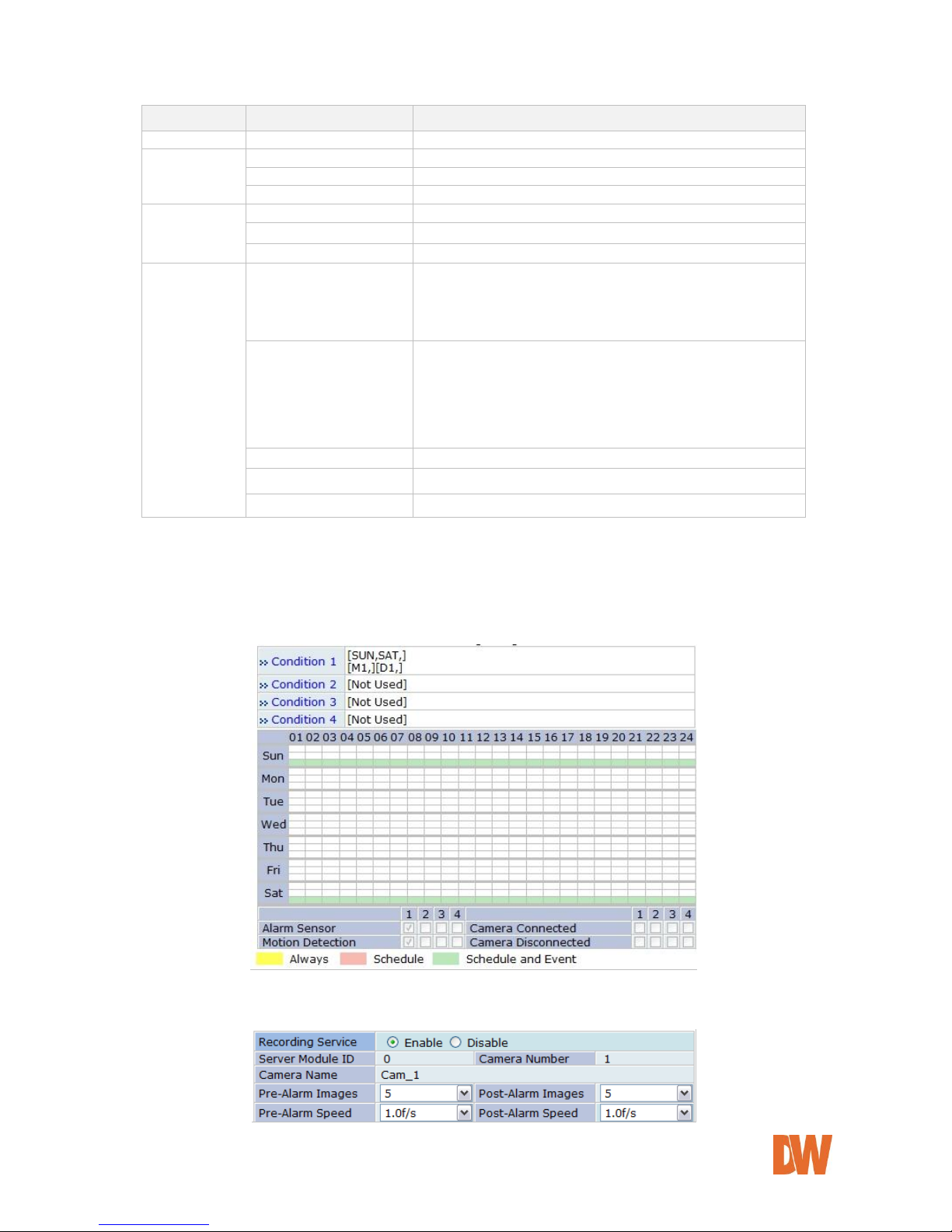
DW-CP04 Manual
01Manual_CP04_05172013 63
Category
Item
Description
Select Mode
Always
Recording is enabled all the time.
Schedule Only
Recording is done by configured schedule.
Event Only
Recording is controlled by configured event.
Schedule and Event
Recording is controlled by both schedule and event.
Schedule
Week
Set day of week
Time
Set time
Date
Set date
Event
Alarm Sensor
Each of 1, 2, 3, 4 refers to the sensor number, and
checked when Event-Driven Recording is selected.
If all the four sensors are checked together, recording is
enabled only when all four sensor are activated.
Motion Detection
Each of 1, 2, 3, 4 refers to the sensor number, and
checked when Motion Detection Recording is selected.
If all the four sensors are checked together, recording is
enabled only when all four sensor are activated.
When Hardware motion detection is used, you should set
the detection area in Camera & Motion section.
External Input Data
Recording is enabled when the data is externally input.
Camera Connected
Recording is enabled when camera signal is detected.
Camera Disconnected
Recording is enabled when camera signal is not detected.
Click Enable to activate a condition, and select the recording configuration, set the date and time limitations
(if applicable), and select which sensors and which motion alarms will trigger video recording. Once recording
conditions are set for an individual camera, the recording settings will appear in the Recording
Configuration screen as seen below.
Make sure the Recording Service below the calendar graph is set to Enable.
Page 64

DW-CP04 Manual
01Manual_CP04_05172013 64
If event recording is selected, adjust the pre and post alarm recording duration and frame-rate.
If continuous recording is selected, the speed set under
Pre-Alarm speed will be the recording speed
continuously.
If scheduled recording is selected, the speed set under
Pre-Alarm speed will be the recording speed when the
camera is set to be recording.
If Event recording is selected, the speed set under PreAlarm speed will be the recording speed before the
event takes place, and the Post-Alarm speed will be the
recording speed after the event is triggered.
If there are two recording conditions configured, it can start recording when at least one condition is valid.
After configuration is finished, click the Save to apply the change and return to previous screen.
Now you will notice that the Recording Configuration is made. If the video is already being recorded, the
status will display Recording. Click Apply to save the changes.
If recording conditions are configured properly and video is not being recorded at the moment, you need to
click the Record button to start recording.
Note: Record button will become Stop button after pressing. If you want stop
recording, click the Stop button again.
Page 65

DW-CP04 Manual
01Manual_CP04_05172013 65
10.3. View Recording Profile
You can get the overview of the recording configuration by clicking View Recording Profile on the menu.
It will display a pop-up window that shows the recording configuration in one screen as seen below.
10.4. Recording Mode
When the SD card or HDD become full, select whether to overwrite (circulation), or stop recording when the
SD card is full.
Circulation: The base file size for video is 630 Mbytes in HDD. So every time the HDD is out of
space, it will delete the oldest 630 Mbytes file to make space.
Pause at full: When the HDD is out of space, it will stop recording and display STOP status. You
can setup e-mail notifications when the HDD is full and stops recording.
You can set a time limit on how long the recorded video will be kept in the hard drive by putting a check on
Restrict Duration. If selected, a time setting menu will be enabled to enter in days. The default is 90 days
and it can be changed between 1 and 3650. For instance, if it’s set to 3 days, only the video from the last 3
days will be kept.
Page 66

DW-CP04 Manual
01Manual_CP04_05172013 66
10.5. SD Status Report
The SD Status Report menu allows you to setup e-mail notifications regarding the storage’s status. Click SD
Status Report on Recording Configuration menu. Set the condition of SD status for sending email, and
Date/Time when email is sent.
Enter the receiving email addresses and the default contents of the notification.
Disk Full Notification
Select Enable to use this feature.
Periodic Notification
Select Enable if you want to receive the HDD capacity information on
specific Day of week and Time.
Day & Time
Set the Day of week and Time you want to receive email notification.
(Above Example: Receiving SD capacity information at 3 pm every
Monday and Wednesday)
SD Error Notification
Select Enable if you want to receive a notification upon SD Error.
SD Error Beep Sound
Select Enable if you want to sound Beep upon SD Error.
Page 67

DW-CP04 Manual
01Manual_CP04_05172013 67
SMTP Server
IP address of the server for email service.
Authentication Login
Select Enable if the SMTP server requires user authentication.
User ID
User ID for authentication login
Password
Password for the User ID
Sender
Email address of sender
1st Recipient
Email addresses of the recipients (up to 3 persons).
2nd Recipient
3rd Recipient
User Defined Message
Contents of the message to add in the notification.
10.6. Clear Recording Configuration
Using the Clear Recording Configuration you can clear all the contents of Recording Configuration in a single
step. Click Clear Recording Configuration on Recording Configuration menu. Click Clear button, and a
confirmation window will be displayed as below. Click OK to delete all previous recording configurations, or
cancel to exit.
10.7. Delete Recorded Data
The Delete Recorded Data menu allows you to delete all previously recorded data on the HDD or SD card.
Click Delete Recorded Data on Recording Configuration menu. The following window will be displayed.
Select the HDD to be deleted, and click Delete. A confirmation window will be displayed as below. Click OK
to delete all the stored video data or cancel to exit.
Page 68

DW-CP04 Manual
01Manual_CP04_05172013 68
11. Utilities
In the Utilities part of the Admin menu, you can view the system log file, save any changed configurations,
reboot the Compressor, restore the factory default conditions, and update the system.
11.1. System Log
Select the System Log menu to view what users connected to the Compressor, their IP address, and
which section of the web viewer was accessed (Live/ admin/ player/ home).
11.2. Save Configuration
If you have made multiple configuration changes in the Compressor’s admin menu, go to the Save
Configuration menu to make sure all current settings are saved instantly.
Page 69

DW-CP04 Manual
01Manual_CP04_05172013 69
11.3. Reboot
It is recommended to reboot the system after making changes and saving the configuration. To reboot, click
“Reboot" on Utilities menu. A confirmation screen will be displayed as shown Click “Save Configuration”
button, otherwise click “Back” button to cancel the rebooting.
The second confirmation screen will be shown. This will confirm to close the Compressor’s web viewer page.
Click “OK” button to close the web browser and reboot right away. If you click “Cancel”, the web browser is
still open, but you will not be able to access the Compressor Server until the rebooting is finished.
11.4. Factory Default
When selected, the Compressor will return to factory default conditions for all settings and configurations
except Network configuration. Click “Factory Default” in the Utilities menu. A confirmation screen will be
displayed. Click “Factory Default” to return the Compressor to its factory settings, or “Back” to cancel. The
second confirmation screen will appear. Click “OK” to restore the factory default condition right away. If you
click “Cancel”, web browser will go back to the previous screen without any changes made.
Page 70

DW-CP04 Manual
01Manual_CP04_05172013 70
11.5. System Update
In order to update the system, click “System Update” on Utilities menu, then the following window will be
displayed. Chose the appropriate upgrade and press the Start button.
System upgrade can also be complete using the IP Installer tool.
All (Firmware, RAM disk, System, Web) Update: Update all four system images.
System and Web Update: Only System and Web images are to be updated.
Web Only Update: Only Web image is to be updated.
Visit Digital Watchdog’s website at www.digital-watchdog.com to download the latest firmware for the
Compressor.
11.5.1. Update by Item
Click the “Start” button next to All (Firmware, RAM disk, System, Web) Update and the other items
on the menu, and a confirmation window will appear. Click “OK” to proceed the update. The
Compressor’s web page will close, and an upgrade window will appear.
Browse and select the upgrade file from your PC’s directory. Click Next.
Follow the instructions and upload each of the necessary files.
Select whether the Compressor should return to factory settings when the upgrade is complete, or click
Next to save all current settings and configurations. The system will update the Compressor. Do not
close the window until the installation is complete.
When the upgrade is complete, press the ‘Reboot’ button to reboot the server and apply all changes.
Page 71

DW-CP04 Manual
01Manual_CP04_05172013 71
12. Appendix
12.1. Troubleshooting the Compressor Smart Live Viewer
12.1.1. Installation
Q) I can't start installation of SmartViewer when I connect to the Compressor and click Live View.
A) The Internet connection is not available. Manual installation is required.
Q) It stopped during the installation showing the message 'Process is being used'.
A) Close all the Internet Explorer windows running, and try installing again.
Q) 'Reboot system' message is displayed after installation is finished.
A) SmartViewer was being used in another Internet Explorer during installation. Reboot is required.
Q) After installation is finished, it requires me to install SmartViewer again.
A) It is the case when SmartViewer program was updated. Install SmartViewer again.
Q) I still can't install SmartViewer despite the Internet connection is available.
A) It is cause by deleting any part of SmartViewer. Uninstall and reinstall SmartViewer.
12.1.2. Server
Q) It shows a message saying ‘Failed to retrieve server information from SmartViewer or unauthorized
user access.’
A) Make sure the followings:
The access to the Compressor is good on Internet Explorer.
At least one camera is authorized for video viewing.
At least one remote server is registered if you’re running a network video record without a
local camera.
12.1.3. Video
Q) I can't see live view on screen.
A) Make sure that at least one camera is registered in groups of network video recorder. Also check
whether Channel Hide button is pressed. If so, select the channel to see.
Q) ‘Connecting’ or ‘Disconnected’ message is displayed during live view.
A) It may be caused by either the network is not available or the Compressor is turned off or rebooting.
Check if the network is working properly and the Compressor is turned on. If you still see the same
message while the network is good and the power is on, try rebooting the Compressor.
Q) ‘Extra users’ message is displayed in live view.
A) It is displayed when there are excessive numbers of users viewing the video. You will be able to see
the video when any of current users disconnects from the server.
Q) 'No Signal' is displayed in live view.
A) Camera may be disconnected from the Compressor. Make sure all cameras are properly connected
to the Compressor and all power and video cables are intact.
Page 72

DW-CP04 Manual
01Manual_CP04_05172013 72
Q) Frame rate of live view is getting low.
A) It is caused by slow network. Improve the network condition or cancel the real-time monitoring by
any other software.
Q) Only live view is displayed without Internet Explorer.
A) Click ESC key to escape from Full Screen mode in SmartViewer.
Q) I can't save images.
A) Make sure you have the permission to the folder. And check if you have enough space in hard drive.
Q) I can't save videos.
A) Make sure you have the permission to the folder. And check if you have enough space in hard drive.
Q) Video recording stopped by itself.
A) Video can be saved up to 10 minutes. It automatically stops recording if it exceed the 10 minutes. It
also stops recording when image size is modified, video codec is changed, or video input is removed.
For network video recorders, video input is removed when it is moved to other group. For network
video servers or cameras, video input is removed when the channel button is pressed.
12.1.4. Audio
Q) Audio is not played.
A) First check if Audio-In port is connected to an audio source, and then select the camera linked to the
Audio-In port on SmartViewer. Check if Mute is activated. Check if the computer has the sound card
driver properly installed. Also check the level of speaker volume.
Q) I can't send audio to the Compressor.
A) Sending audio from SmartViewer to the Compressor is only allowed to the user who used that
feature for the first time. Any other user can only receive audio from the server. Check if the computer
has the sound card driver properly installed. Also check the level of speaker volume.
12.1.5. PTZ
Q) PTZ Control bar is not activated.
A) Connect to the Compressor, and make sure PTZ set up is properly done on Admin menu.
Q) Clicking PTZ buttons doesn’t work.
A) When network condition is not good enough, there may be some latency time in camera movement.
Try Step Mode if Move mode is currently set to Continuous.
Q) Advanced features for PTZ don’t work.
A) Advanced features are only available for the supported cameras. Make sure the PTZ camera in use
supports the advanced features.
12.1.6. Relay Output
Q) Relay Output button won’t be activated.
A) The second channel of Dual Stream can be controlled only after Primary channel is set up for Relay
Output control. Also make sure that the Compressor is connected to the network.
Q) Relay Output button won’t work.
Page 73

DW-CP04 Manual
01Manual_CP04_05172013 73
A) Make sure that the Compressor is connected to the network.
12.1.7. Other
Q) An error occurs if Internet Explorer is closed while SmartViewer is working.
A) It can be caused if you’re using Internet Explorer 6.0. Upgrading Internet Explorer to 7 or higher can
solve the issue.
 Loading...