

Page 1

Digital Voice Systems, Inc.
The Speech Compression Specialists
VC-20-PRJ25
IMBE™ Vocoder Board
User’s Manual
Version 2.0
Page 2

VC-20-PRJ25 IMBE™ Vocoder Board
User’s Manual
Version 2.0
Copyright , 1998
Digital Voice Systems, Inc
234 Littleton Raod
Westford , MA 01886
This document may not, in whole or in part be copied, photocopied, reproduced, translated, or reduced to any
electronic medium or machine readable form without prior consent in writing from Digital Voice Systems,
Incorporated.
Every effort has been made to ensure the accuracy of this manual. However, Digital Voice Systems, Inc. makes no
warranties with respect to the documentation and disclaims any implied warranties of merchantability and fitness for
a particular purpose. Digital Voice Systems, Inc. shal l not be liable for any errors or for incidental or consequential
damages in connection with the furnishing, performance, or use of this manual or the examples herein. The
information in this document is subject to change without notice.
Trademarks
VC-20 IMBE Vocoder Board is registered trademarks of Digital Voice Systems, Inc. Other product names
mentioned may be trademarks or registered trademarks of their respective companies and are the sole property of
their respective manufacturers.
All Rights Reserved
Data subject to change
Page 3

VC-20-PRJ25 IMBE™ Vocoder Board END USER License Agreement
1.0 Preliminary Statements and Definitions
1.1 "Voice Codec" shall mean the hardware, software and
associated documentation referred to in the invoice or shipping papers
accompanying this agreement for which END USER has requested a
license, and any derivative works thereof, including modifications,
enhancements and extensions made by or for Digital Voice Systems,
Inc. (DVSI) and including circuit diagrams, timing diagrams,
programmable logic software, logic diagrams, layouts, operating
instructions and user manuals.
1.2 "IMBE™ Software" shall mean the speech coding software
and/or firmware provided as part of the Voice Codec. This software is
contained in the Read Only Memories (ROMS, EPROMS, EEPROMS,
etc...) which are included as part of the Voice Codec. This software
includes any derivative works which have as their source the software
contained in the Read Only Memories, and it includes the software
contained in any future Read Only Memories which DVSI may provide
END USER for use in the Voice Codec.
1.3 "Designated Site" shall mean the location of the Voice Codec.
1.4 "Proprietary Information" shall mean the information
which DVSI desires to protect against unrestricted disclosure or
competitive use and which is designated as such in writing by DVSI or
is disclosed orally and within thirty (30) days thereafter is reduced to
tangible form pursuant to this License.
1.5 DVSI represents that it owns certain “Proprietary Rights” in
the Technology and the IMBE Voice Compression Software,
including patent rights in the Technology, and patent rights,
copyrights, and trade secrets in the IMBE Voice Compression
Software.
2.0 License Granted
2.1 Subject to the conditions herein and upon initial use of the
IMBE™ Software within the VC-20 IMBE™ Vocoder Codec, DVSI
hereby grants to END USER a non-exclusive, limited license to use the
IMBE® Voice Compression Software in machine readable form solely
on the IMBE-1000™ Vocoder Chip. Title to the IMBE® Voice
Compression Software remains with DVSI. No license is granted for
use of the IMBE® Voice Compression Software on other than the
Voice Codec. No license, right or interest in any trademark, trade
name or service mark of DVSI is granted under this Agreement.
2.2 END USER shall not copy, extract, de-compile, reverse
engineer or disassemble the IMBE® Voice Compression Software
contained in the VC-20 IMBE™ Vocoder Board.
2.3 Transfer of License
(a) END USER may transfer the IMBE™ Software and all
rights under this agreement to a third party together with a copy of
this Agreement provided that END USER provides DVSI with a
written notification of the transfer and provided that the third party
agrees in writing to accept all the terms and conditions of this
agreement. Upon any such transfer, END USER's rights under this
Agreement shall terminate pursuant to Section 3.0.
(b) END USER may relocate the Voice Codec, and the
subsequent location shall then be considered the Designated Site.
(c) Except as provided in this Section 2.2, this Agreement,
the IMBE™ Software and any other information provided by
DVSI to END USER and any licenses and rights granted hereunder,
may not be sold, leased, assigned, sublicensed or otherwise
transferred, in whole or in part, by END USER.
2.4 END USER shall not de-compile, reverse engineer or
disassemble the IMBE™ Software.
3.0 Term and Termination
3.1 This Agreement is effective upon initial use of the
IMBE™ Software on the Voice Codec and shall remain in effect
until terminated in accordance with this agreement.
3.2 This Agreement shall terminate automatically without
notice from DVSI if END USER fails to comply with any of the
material terms and conditions herein. END USER may terminate
this Agreement at any time upon written notice to DVSI
certifying that END USER has complied with the provisions of
Section 3.3.
3.3 Upon termination of this Agreement for any reason,
END USER shall: (i) have no further rights to the IMBE™
Software; (ii) discontinue all use of the IMBE™ Software; and (iii)
destroy or, at DVSI's option, return all copies of the IMBE™
Software.
4.0 Payments
4.1 In consideration of the hardware, software, and
associated materials provided as part of the Voice Codec, and in
consideration of the license and rights in the IMBE™ Software
granted by DVSI, and in consideration of DVSI's performance of
its obligations hereunder, END USER agrees to pay to DVSI the
fee specified in DVSI's invoice.
4.2 In consideration of the materials provided as part of the
Voice Codec, and in consideration of the license and rights in the
IMBE Voice Compression Software granted by DVSI, and in
consideration of DVSI's performance of its obligations hereunder,
END USER agrees to pay to DVSI the fee specified in DVSI's
invoice.
5.0 Proprietary Notices
5.1 END USER shall not remove any copyright or proprietary
notice on the on the IMBE Voice Compression Software or VC20 IMBE™ Vocoder Board.
6.0 Proprietary Information
6.1 The parties agree that the IMBE Voice Compression
Software shall be considered Proprietary Information.
DVSI Confidential Proprietary
Page i
Page 4

VC-20-PRJ25 IMBE™ Vocoder Board
User’s Manual
License and Warranty
6.2 Except as otherwise provided in this Agreement, END USER
shall not use, disclose, make, or have made any copies of the
Proprietary Information, in whole or in part, without the prior
written consent of DVSI.
6.3 END USER shall make reasonable efforts to notify and
inform its employees having access to the Proprietary Information of
END USER's limit ations, duties and obligations regarding nondisclosure
and copying of the IMBE™ Software. Proprietary Information shall
be used only by employees of END USER and only at the Designated
Site, except as provided under this agreement.
6.4 END USER shall have no obligations for disclosure or use of
Proprietary Information which: (i) is already known to END USER, at
time of disclosure by DVSI; (ii) is or becomes publicly known through
publication, inspection of product or otherwise through no wrongful
act of END USER; (iii) is received from a third party without
restriction and without breach of this Agreement; (iv) is independently
developed by END USER; (v) is disclosed to a third party by or on
behalf of DVSI without restriction; or (vi) is approved for release or
use by written authorization of DVSI.
6.5 Notwithstanding any termination pursuant to Section 3.0,
the obligations set forth in this Section 6.0 shall survive termination
of this Agreement.
7.0 Limited Warranty
7.1 DVSI warrants the Voice Codec and the IMBE™ Software
to be free from defects in materials and workmanship under normal
use for a period of ninety (90) days from the date of delivery. DVSI
further warrants that the Voice Codec and the IMBE™ Software
operate in accordance with the written specifications delivered to
END USER with the Voice Codec.
7.2 Except as stated in Section 7.1, the Voice Codec and
IMBE™ Software are provided "as is" without warranty of any kind.
DVSI does not warrant, guarantee or make any representations
regarding the use, or the results of the use, of the Voice Codec or
IMBE™ Software wi th respect to its correctness, accuracy, reliability,
currentness or otherwise. The entire risk as to the results and
performance of the Voice Codec or IMBE™ Software is assumed by
the END USER. After expiration of the warranty period, END USER,
and not DVSI or its employees, assumes the entire cost of any
servicing, repair or correction of the Voice Codec or the IMBE™
Software.
7.3 DVSI warrants that it has the right to enter into this
Agreement and to grant a license to use the IMBE™ Software to END
USER.
7.4 Except as specifically set forth in this Section 7.0, DVSI
makes no express or implied warranties including, without limitation,
the warranties of merchantability or fitness for a particular purpose or
arising from a course of dealing, usage or trade practice, with respect
to the Voice Codec or IMBE™ Software. Some states do not allow
the exclusion of implied warranties, so the above exclusion may not
apply to END USER. No oral or written information or advice given
by DVSI or its employees shall create a warranty or in any way
increase the scope of this warranty, and END USER may not rely on
any such information or advice. The limited warranties under this
section 7.0 give END USER specific legal rights, and END USER
may have other rights which vary from state to state.
8.0 Limitation of Liability
8.1 In no event shall DVSI be liable for any special, incidental,
indirect or consequential damages resulting from the use or
performance of the Voice Codec or VC-20 IMBE™ Vocoder
Board whether based on an action in contract, tort (including
negligence) or otherwise (including, without limitation, damages
for loss of business profits, business interruption, and loss of
business information), even if DVSI or any DVSI representative
has been advised of the possibility of such damages.
8.2 Because some states do not allow the exclusion or
limitation of liability for consequential or incidental damages, the
above limitations may not apply to END USER.
8.3 DVSI's maximum liability for damages arising under this
Agreement shall be limited to 20% (twenty percent) of the fees
paid by END USER for the particular Voice Codec or VC-20
IMBE™ Vocoder Board which caused the damages or that is the
subject matter of, or is directly related to, the cause of action.
9.0 Taxes
9.1 All payments required under Section 4.0 or otherwise
under this Agreement are exclusive of taxes and END USER agrees
to bear and be responsible for the payment of all such taxes
(except for taxes based upon DVSI's income) including, but not
limited to, all sales, use, rental receipt, personal property or other
taxes which may be levied or assessed in connection with this
Agreement.
10.0 Export
10.1 United States export laws and regulations prohibit the
exportation of certain products or technical data received from
DVSI under this Agreement to certain countries except under a
special validated license. As of May 20, 1996 the restricted
countries are: Libya, Cuba, North Korea, Iraq, Serbia, Montenegro,
and Iran. The END USER hereby gives its assurance to DVSI that
it will not knowingly, unless prior authorization is obtained from
the appropriate U.S. export authority, export or re-export,
directly or indirectly to any of the restricted countries any
products or technical data received from DVSI under this
Agreement in violation of said United States Export Laws and
Regulations. DVSI neither represents that a license is not required
nor that, if required, it will be issued by the U.S. Department of
Commerce. Licensee shall assume complete and sole
responsibility for obtaining any licenses required for export
purposes.
11.0 Governing Law
11.1 This Agreement is made under and shall be governed by
and construed in accordance with the laws of the Commonwealth
of Massachusetts, except that body of law governing conflicts of
law. If any provision of this Agreement shall be held
unenforceable by a court of competent jurisdiction, that provision
DVSI Confidential Proprietary
Page ii
Page 5

VC-20-PRJ25 IMBE™ Vocoder Board
User’s Manual
shall be enforced to the maximum extent permissible, and the
remaining provisions of this Agreement shall remain in full force and
effect.
12.0 Notices
12.1 Any notices to DVSI which may be given hereunder shall be
in writing and sent to: Digital Voice Systems Inc., 234 Littleton Road,
Westford, MA., 01886, U.S.A.
License and Warranty
DVSI Confidential Proprietary
Page iii
Page 6

Page 7

VC-20-PRJ25 IMBE™ Vocoder Board
User’s Manual
Table of Contents
TABLE OF CONTENTS
Section 1PRODUCT INTRODUCTION............................................................................1
GENERAL I NFORMATION...............................................................................................1
Section 2VC-20-PRJ25 IMBE™ VOCODER OPERATION..........................................2
OPERATION ..................................................................................................................2
Section 3T ECHNICAL SPECIFICATIONS ........................................................................3
VC-20-PRJ25 CONNECTOR SIGNAL DESCRIPTIONS ................................................6
Section 4CHAPTER 2 T ECHNICAL DRAWINGS ............................................................10
Section 5CHAPTER 3 DVSI SUPPORT SERVICES......................................................16
TECHNICAL SUPPORT...............................................................................................16
LIST OF FIGURES
Figure 1 Silence / Voice Frame Signaling.................................................................................9
Figure 2 VC-20-PRJ25 Connections In Loop-Back Mode.......................................................15
Figure 3 Connections between VC-20-PRJ25 and a Modem.................................................16
Figure 4 Dual VC-20- PRJ25 Vocoder Board Connections....................................................17
Figure 5 VC-20- PRJ25 Channel Signal Timing Relationships...............................................18
Figure 6 Run Signal Timing ....................................................................................................20
Figure 7 VC-20-PRJ25 Physica l Dimensions.........................................................................21
DVSI Confidential Proprietary
Page v
Page 8

Page 9

VC-20-PRJ25 IMBE™ Vocoder Board
User’s Manual
Section 1- Introduction
Product Introduction
General Information
The Digital Voice Systems, Inc. (DVSI) VC-20-PRJ25 voice codec is a full-duplex real-time voice
processing board. The VC-20-PRJ25 contains proprietary software which implements the Improved
Multi -Band Excitatio n™ (IMBE™) voice coding algorithm. DVSI grants a license to its customers to
use this software according to the terms established in the attached IMBE™ Software END USER
License Agreement. Use of the VC-20-PRJ25, or any portion thereof, signifies acceptance of these
licensing terms.
The VC -20-PRJ25 operates by digitizing an analog speech signal using an on-board A-to-D converter.
This digitized speech is then processed by the encoder and converted into a 7.2 kbps data bit stream.
This bit stream is out put to a modem or similar device. Simultaneously, the VC-20-PRJ25 receives a
7.2 kbps data bit stream from a modem or similar device. This received bit stream is processed by the
decoder and converted into a synthetic speech signal which is then converted into an analog signal using
the on-board D-to-A converter. The encoder and decoder are fully asynchronous
The VC-20-PRJ25 is capable of supporting advanced features such as external codecs and
downloading custom software. Please contact DVSI for more information on these features.
DVSI Confidential Proprietary
Page 1
Page 10

VC-20-PRJ25 IMBE™ Vocoder Board
User’s Manual
Section 2 - Operation
VC-20-PRJ25 IMBE™ Vocoder Operation
Operation
Connections are made to the VC-20-PRJ25 using the attached DIN 41612 connector
which is described in Sections 4 and 5. The user must supply the VC -20-PRJ25 with a 5v digital
power supply and a +/-5v analog power supply. It is preferable to decouple the analog supply from
the digital supply by using separate power supplies. The VC -20-PRJ25 contains one set of jumpers
which is used to loop-back the encoder signals to the decoder, and to enable the on-board clocks
and frame signals. The pin assignment for this jumper is documented in Section 7
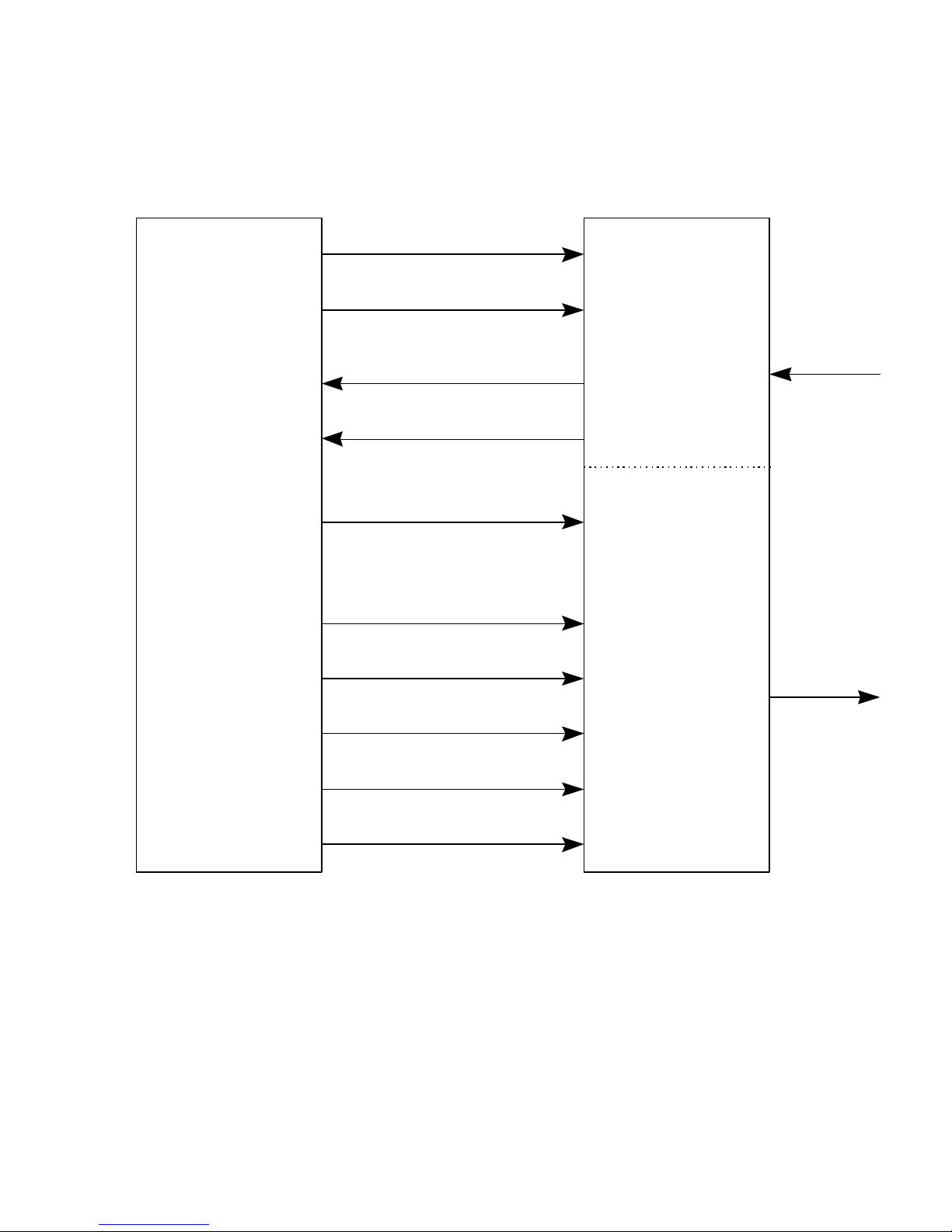
The VC-20-PRJ25 can be operated in loop-back mode by using the internal clock and
frame generator to generate the clock signals, TXCK and RXCK, and the frame signals, FMEN and
FMDE, as shown in Figure 2. Jumpers 1-12 on the fourteen pin jumper block should be connected
and all other jumpers should be disconnected.
The VC -20-PRJ25 can be connected to a modem or similar device as shown in Figure 3.
The modem or the VC-20-PRJ25 can generate the clock and framing signals TXCK, FMEN,
RXCK and FMDE. The modem reads the data from the encoder on the data lines QTXD, ITXD,
and ENSLNCE. Simultaneously the decoder reads data from the modem on data lines QRXD,
QRXD1, QRXD0, IRXD, IRXD1, IRXD0, DESLNCE, HD_SD and LOST. Note: if soft-decision
information is unavailable, then the HD_SD signal should be held high (or left unconnected) so that
only the MSB data signals (QRXD, IRXD) will be read by the decoder. The frame signals FMEN
and FMDE are used to signify the beginning of each data frame for the encoder and decoder,
respectively. The required timing relationship between these signals is shown in Figure 5. In order to
operate in this mode, jumpers 5-10 and 12-14 should be disconnected. If the VC -20-PRJ25 is
generating the clocks and frames, then jumpers 1-4 should be connected, otherwise, they should be
disconnected. Jumper 11 is disconnected if the LOST signal is used, otherwise it is connected.
A final operating mode allows two VC-20-PRJ25's to be connected together using their
on-board clocks to generate the signals TXCK, FMEN, RXCK and FMDE. In this mode the
encoder on the first VC-20-PRJ25 is connected to the decoder on the second VC-20-PRJ25.
Similarly, the decoder on the first VC-20-PRJ25 is connected to the encoder on the second VC-20PRJ25. This is shown in Figure 4. Generally, the encoder signals on each board are synchronized
with the oscillator on that board, and the decoder signals on each board are synchronized with the
oscillator on the other board. This is done by connecting jumpers 1, 3 and 11 on each board. All
other jumpers should be disconnected. The HD_SD control signal must be held high or left
unconnected to disengage soft -decision decoding. Care must be taken that only one clock generator
is connected to each of the clock signals TXCK, FMEN, RXCK and FMDE.
DVSI Confidential Proprietary
Page 2
Page 11

VC-20-PRJ25 IMBE™ Vocoder Board
User’s Manual
Technical Specifications
Connector:
Type DIN 41612 Connector (male)
Physical:
Description 100 mm (Single Euro-card [3U]) height (see Figure 6)
Analog Input:
Type single-ended
Impedance 600 ohm
Sensitivity 0 dBm0 = 0 dBm
Sinusoidal Overload +3.17 dBm0
Nominal Level -23 dBm0 (average speech level)
Dynamic Range +/- 10 dB (relative to Nominal Level)
Noise Level -72 dBm0
Analog Output:
Type single-ended
Impedance low impedance output, capable of driving a 600 ohm load
Sensitivity 0 dBm0 = 0 dBm
Sinusoidal Overload +3.17 dBm0
Nominal Level -23 dBm0 (average speech level)
Dynamic Range +/- 10 dB (relative to Nominal Level)
Noise Level -72 dBm0
Bandwidth 20 – 3700 Hz.
Digital Interface:
Type TTL compatible
Power:
2 watts @ 5v digital, .2 watts @ +/- 5v analog
Section 3 – Technical Specifications
DVSI Confidential Proprietary
Page 3
Page 12
VC-20-PRJ25 IMBE™ Vocoder Board
User’s Manual
Section 3 – Technical Specifications
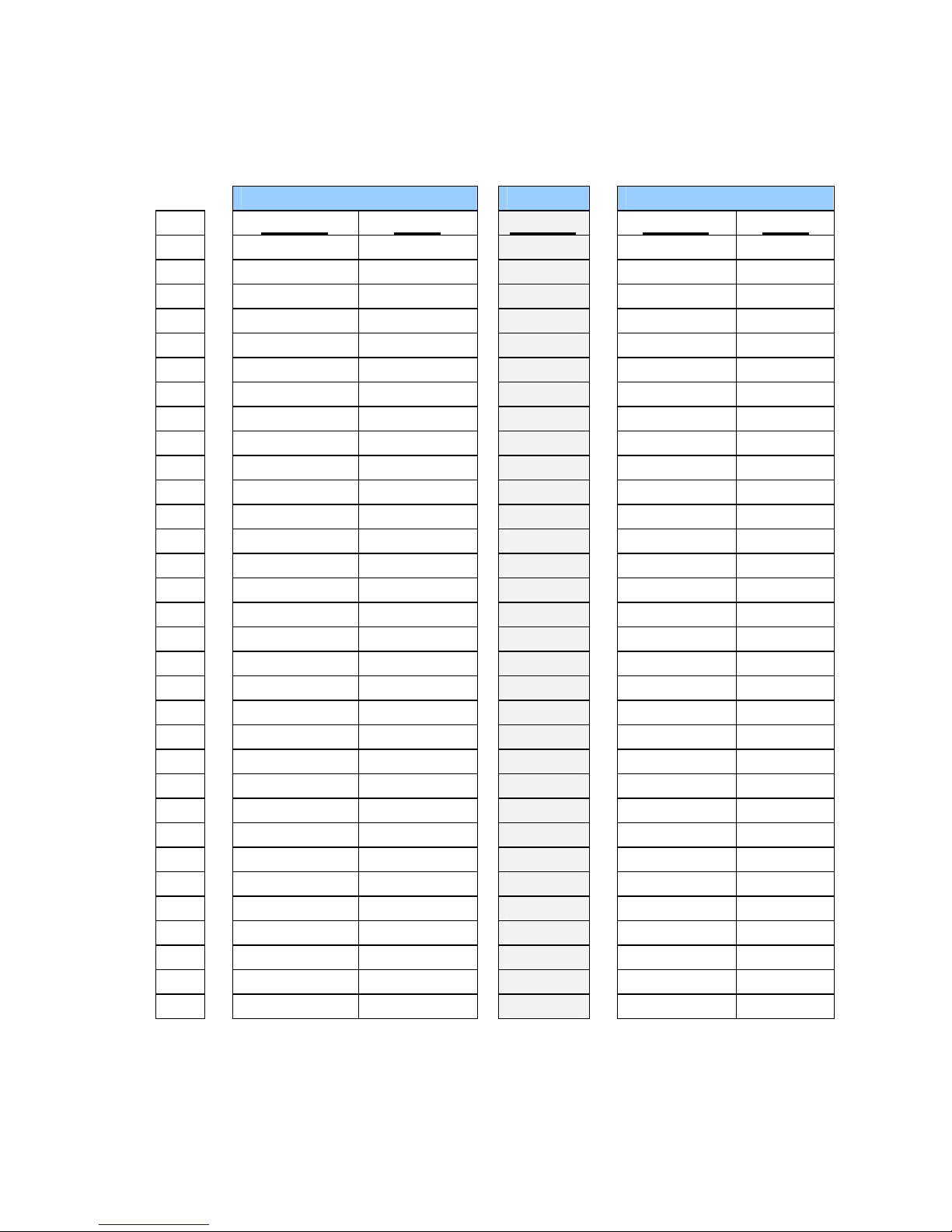
DIN41612 (96-pin Male) Connector Pin Description
Pin Function Name Function Function Name
1
2
Digital Power
Digital Power
3 Ground GND Reserved Ground GND
4 Output ITXD Reserved Output QTXD
5 Reserved Reserved Input TXCK
6 Input FMEN Reserved Output RUN
7 Reserved Reserved Output RESX
8 Ground GND Reserved Ground GND
9 Input IRXD Reserved Input QRXD
10 Reserved Reserved Input RXCK
11 Input FMDE Reserved Reserved
12 Reserved Reserved Reserved
13 Ground GND Reserved Ground GND
14 Reserved Reserved Reserved
15 Output RESET Reserved Input DINRS
16 Output STATUS Reserved Reserved
17 Output ENSLNCE Reserved Reserved
18 Input IRXD1 Reserved Input QRXD1
19 Input IRXD0 Reserved Input QRXD0
20 Ground GND Reserved Ground GND
21 Input LOST Reserved Reserved
22 Reserved Reserved Input HD_SD
23 Reserved Reserved Reserved
24 Input FEC_OFF Reserved Reserved
25 Input DESLNCE Reserved Reserved
26 Ground GND Reserved Ground GND
27
28
Analog Power
Analog Power
29 Output VFRO Reserved Input VFXI
30
Analog Ground
31 Ground GND Reserved Ground GND
32 Ground GND Reserved Ground GND
Note: Many Reserved signals are used to monitor the internal state of the VC-20-PRJ25. To
ensure proper operation all reserved signals must be left unconnected.
ROW C ROW B ROW A
VCC Reserved
VCC Reserved
+5v analog Reserved
-5v analog Reserved
AGND Reserved
Digital Power
Digital Power
Analog Power
Analog Power
Analog Ground
VCC
VCC
+5v analog
-5v analog
AGND
DVSI Confidential Proprietary
Page 4
Page 13

VC-20-PRJ25 IMBE™ Vocoder Board
User’s Manual
VC-20-PRJ25 Connector Signals
Name Type Description
VCC Power Digital +5v +/- 5%
GND Power Digital Ground
+5v Power Analog +5v +/- 10%
-5v Power Analog -5v +/- 10%
GND Anlg Power Analog Ground
ITXD Output Transmit data I channel
QTXD Output Transmit data Q channel
TXCK Inpu t Transmit data bit clock (3.6 kHz)
FMEN Input Encoder frame flag (Active High)
IRXD Input Receive data I channel (MSB)
IRXD1 Input Receive data I channel
IRXD0 Input Receive data I channel (LSB)
QRXD Input Receive data Q channel (MSB)
QRXD1 Input Receive data Q channel
QRXD0 Input Receive data Q channel (LSB)
RXCK Input Receive data bit clock (3.6 kHz)
FMDE Input Decoder frame flag (Active High)
LOST Input Lost speech frame detected flag (Active High)
RESET Output Voice codec reset flag (Active High)
Section 3 – Technical Specifications
STATUS Output Voice codec status flag (Active High)
ENSLNCE Output Encoder Silence Detected (Active Low) Disabled
DESLNCE Input Decoder silence control (Active Low)
VFRO Output Analog speech output signal
VRXI Input Analog speech input signal
RUN Output Run Status Signal (Active High)
RESX Output Internal Reset Status (Active Low)
DINRS Input Reset Signal (Active High)
HD_SD Input Enable Soft-decision Decoding (Active Low)
FEC_OFF Input Disable error correction and interleaving (Active Low)
DVSI Confidential Proprietary
Page 5
Page 14

VC-20-PRJ25 IMBE™ Vocoder Board
User’s Manual
Section 3 – Technical Specifications
VC-20-PRJ25 Connector Signal Descriptions
DESLNCE The DESLNCE flag signals the decoder that silence has been detected during the
current frame. IF DESLNCE is active while FMDE is high, the decoder ignores the
current frame of channel data and mutes the output VFRO.
DINRS DINRS is a VC -20-PRJ25 reset signal. An active high level on DINRS for a duration
of at least 300ns will reset the VC-20-PRJ25. DINRS will generate RESX and
RESET. The VC -20-PRJ25 will pull this signal to its inactive state (low) when it is not
being driven by an external source (it may be left unconnected if not being used).
ENSLNCE The ENSLNCE flag is activated (low) by the encoder if it detects silence on VRXI.
The ENSLNCE flag is deactivated (high) by the encoder two frames prior to the onset
of voice activity. This is shown in figure 1. Note: silence detection is currently disabled,
consequently ENSLNCE is never active.
SilenceVoice VoiceVoice Silence
FMEN
ENSLNCE
Figure 1: Voice/Silence Detection Timing
FEC_OFF The FEC_OFF signal can be pulled low to disable all error correction and interleaving.
If FEC_OFF is pulled low, the prioritized bit vectors (88 bits) are output on ITXD and
QTXD durring the first 44 clock cycles of each 20 ms transmit frame, and ITXD and
QTXD are set to zero during the remaining 28 clock cycles of each transmit frame.
Also if FEC_OFF is pulled low, the prioritized bit vectors must be input on IRXD2 -0
and QRXD2-0 during the first 44 clock cycles of each 20 ms receive frame, and
IRXd2-0 and IRXd2-0 are ignored during the remaining 28 clock cycles of each
receive frame. The FEC_OFF signal is sampled once every 20 ms when FMEN is
high. If left unconnected, this signal is pulled internally to its inactive state (high).
FMDE This is the decoder frame flag which identifies the frame boundary of the channel input
data. FMDE must be active for one clock period of RXCK every 20 ms.
FMEN This is the encoder frame flag which identifies the frame boundary of the channel output
data. FMEN must be active for one clock period of TXCK every 20 ms.
DVSI Confidential Proprietary
Page 6
Page 15

VC-20-PRJ25 IMBE™ Vocoder Board
User’s Manual
Section 3 – Technical Specifications
GND,
AGND
GND is the digital ground signal and AGND is the analog ground signal. These signals
are connected on the VC-20-PRJ25.
HD_SD The HD_SD signal must be set low to enable soft-decision decoding. This signal is
sampled once every 20 ms data frame. If left unconnected, this signal is pulled internally
to its inactive state (high).
IRXD,
IRXD1, and
IRXD0
IRXD, IRXD1, and IRXD0 are the in-phase data signals. These signals provide three
bits of soft -decision information, with IRXD being the MSB and IRXD0 being the LSB.
If the HD_SD control signal is low (soft-decision mode enabled), then all three data
signals are read by the decoder. If HD_SD is high, then only IRXD (the MSB) is read
by the decoder. These signals are each clocked into the VC -20-PRJ25 on the falling
edge of RXCK at 3.6 kHz. These signals combined with the quadrature-phase data
signals result in a total data rate of 7.2 kbps.
ITXD and
QTXD
ITXD and QTXD are the in-phase and quadrature-phase voice data signals from the
VC-20-PRJ25 encoder. These signals are each clocked at 3.6 kHz, giving a total data
rate of 7.2 kbps.
LOST The LOST flag is active if the current frame of channel data is invalid, in which case the
decoder ignores the current frame of channel data and performs a frame repeat. This
flag is only monitored during the first clock period of each frame.
RESET The RESET signal is a software flag that indicates that the voice codec had been reset
or that the encoder had lost synchronization. The VC -20-PRJ25 is reset under three
conditions: during power-up, as a result of DINRS being asserted, or as a result of a
Watch -Dog Timer reset. When the VC-20-PRJ25 successfully restarts from a reset or
a loss of encoder synchronization, it will set the RESET flag high for one clock cycle of
TXCK. This flag is synchronous with the rising edge of TXCK. RESET is a software
flag; whereas, RESX is the hard-reset signal.
RESX RESX is the reset status output signal. It is active when the VC-20-PRJ25 is being
reset. The VC -20-PRJ25 is reset under three conditions: during power-up, as a result
of DINRS being asserted, or as a result of a Watch-Dog Timer reset. This signal is an
active low output. RESX is the VC-20-PRJ25's actual hard-reset signal; whereas,
RESET is a software flag that is synchronous with TXCK.
RUN RUN is a status signal that signifies that the VC -20-PRJ25 is encoding and decoding
speech. This signal drives the green RUN LED. Each data frame is divided into an
encoder window and a decoder window. The RUN signal is active within each
respective window when the VC -20-PRJ25 is encoding or decoding speech (see figure
6). RUN is synchronous with TXCK.
DVSI Confidential Proprietary
Page 7
Page 16

VC-20-PRJ25 IMBE™ Vocoder Board
User’s Manual
Section 3 – Technical Specifications
RXCK This is the decoder symbol clock which controls the transfer of the channel data into the
decoder. This signal must be 3.6 kHz +/- .05%. IRXD, IRXD1, IRXD0, QRXD,
QRXD1, QRXD0, FMDE, LOST and DESLNCE are synchronous with the rising
edge of this clock signal to within 500 ns.
QRXD,
QRXD1,
and
QRXD0
QRXD, QRXD1, and QRXD0 are the quadrature-phase data signals. These signals
provide three bits of soft-decision information, with QRXD being the MSB and
QRXD0 being the LSB. If the HD_SD control signal is low (soft-decision mode
enabled), then all three data signals are read by the decoder. If HD_SD is high, then
only IRXD (the MSB) is read by the decoder. These signals are each clocked into the
VC-20-PRJ25 on the falling edge of RXCK at 3.6 kHz. These signals combined with
the in-phase data signals result in a total data rate of 7.2 kbps.
STATUS The STATUS flag indicates the status of the voice codec. During normal operation, the
voice codec sets this flag high for one clock cycle of TXCK every data frame.
Absence of this signal during any data frame indicates an error condition. This flag is
synchronous with the rising edge of TXCK.
TXCK This is the encoder data clock which controls the transfer of the channel data out of the
encoder. This signal must be 3.6 kHz +/- .05%. ITXD, QTXD, FMEN, ENSLNCE,
RESET, STATUS, and RUN are synchronous with the rising edge of this clock signal
to within 500 ns.
VFRO VFRO is the analog speech output produced by passing the decoder output through a
16 bit linear codec. VFRO has an analog bandwidth of 100 Hz. - 3600 Hz., and it is
constrained to be within +/- 1.5 volts.
VFXI is the analog speech input which is filtered with a 100 Hz. - 3600 Hz. bandpass
VRXI
filter and then input to the encoder via a 16 bit linear codec. In order to avoid clipping
VRXI must not exceed +/- 1.5 volts.
DVSI Confidential Proprietary
Page 8
Page 17

VC-20-PRJ25 IMBE™ Vocoder Board
User’s Manual
VC-20-PRJ25 on-board jumpers Connector Signals
Jumper Signal
1 Connects on-board 3.6 kHz data clock to TXCK
2 Connects on-board 3.6 kHz data clock to RXCK
3 Connects on-board 20 ms frame clock to FMEN
4 Connects on-board 20 ms frame clock to FMDE
5 Connects ITXD to IRXD0 (LSB)
6 Connects ITXD to IRXD1
7 Connects ITXD to IRXD (MSB)
8 Connects QTXD to QRXD0 (LSB)
9 Connects QTXD to QRXD1
10 Connects QTXD to QRXD (MSB)
11 Deactivates LOST signal
12 Deactivates DESLNCE signal
13 reserved (leave unconnected)
14 reserved (leave unconnected)
Section 3 – Technical Specifications
DVSI Confidential Proprietary
Page 9
Page 18

VC-20-PRJ25 IMBE™ Vocoder Board
User’s Manual
Chapter 2 Technical Drawings
On-Board
Clock & Frame
Generator
Section 4 – Technical Drawings
(jumper 2)
(jumper 1)
(jumper 3)
(jumper 12)
(jumper 4)
(jumpers 5,6,7)
IRXD, IRXD1, IRXD0
TXCK
FMEN
ENSLNCE
(jumpers 8,9,10)
QRXD, QRXD1, QRXD0
DESLNCE
ITXD
QTXD
FMDE
RXCK
ENCODER
DECODER
VFXI
VFRO
Figure 2: Vocoder Connections in Loop back Mode
DVSI Confidential Proprietary
LOST
(jumper 11)
Page 10
Page 19
VC-20-PRJ25 IMBE™ Vocoder Board
ITXD,QTXD
DESLNCE
ENCODER
DECODER
MODEM
VFXI
User’s Manual
Note: Not meant to represent an “off-the-shelf” modem
Section 4 – Technical Drawings
HD_SD, ECHO, VAD
IRXD, IRXD1, IRXD0
QRXD, QRXD1, QRXD0
TXCK
FMEN
ENSLNCE
FMDE
RXCK
LOST
Figure 3: Connections between Vocoder and a Modem
VFRO
DVSI Confidential Proprietary
Page 11
Page 20
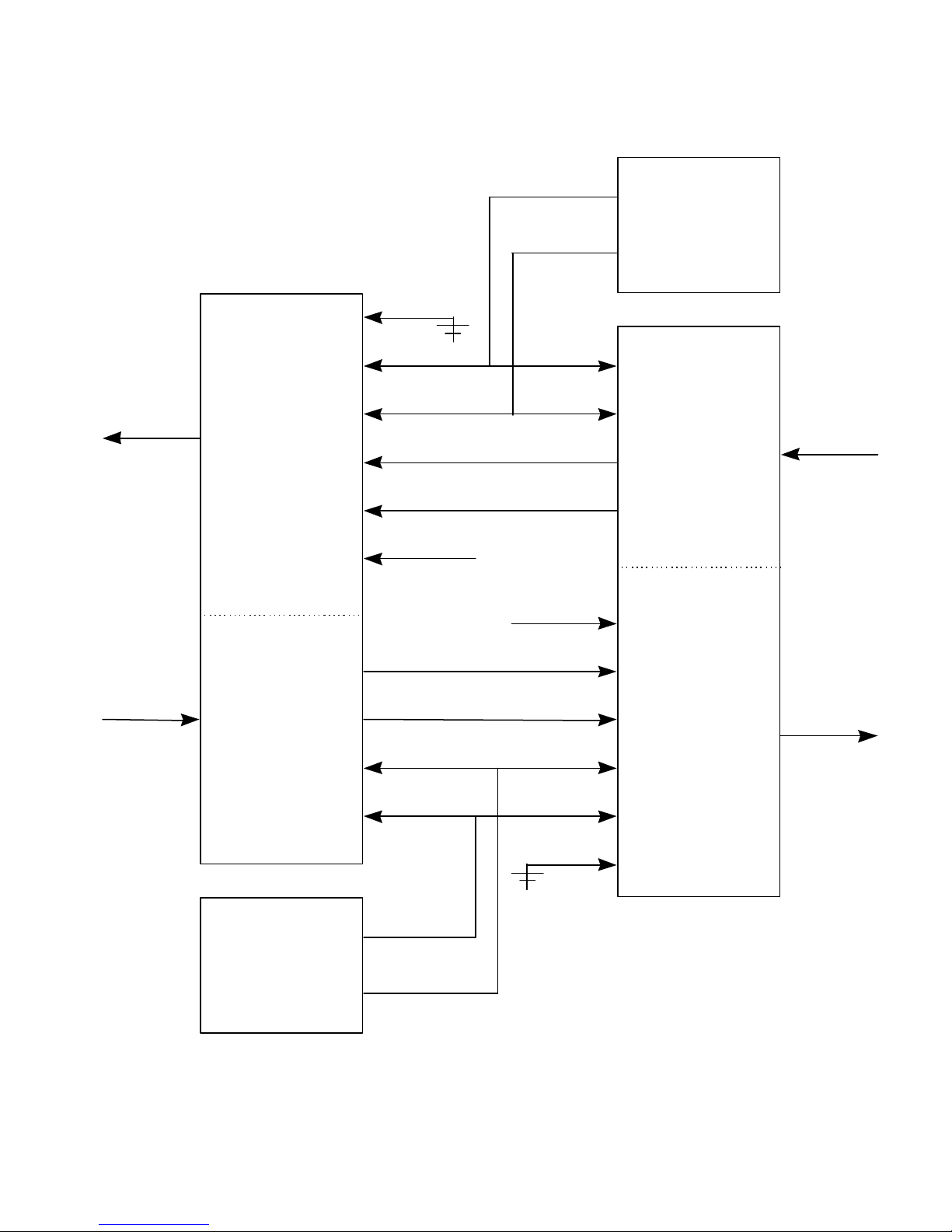
VC-20-PRJ25 IMBE™ Vocoder Board
ENCODER
#2
DECODER
#2
ENCODER
#1
DECODER
#1
#2
(jumper 11)
(jumper
3) (jumper 1)
(jumper 3)
(jumper 11)
(jumper 1)
(jumper 12)
User’s Manual
Section 4 – Technical Drawings
On-Board
Clock & Frame
Generator
#1
LOST
VFRO
VFXI
RXCK
FMDE
DESLNCE
(jumper 12)
IRXD,QRXD
HD_SD, ECHO, VAD
HD_SD, ECHO, VAD
ITXD,QTXD
ENSLNCE
FMEN
TXCK
FMEN
ENSLNCE
ITXD,QTXD
IRXD,QRXD
DESLNCE
FMDE
VFXI
VFRO
On-Board
Clock & Frame
Generator
Figure 4: Dual Vocoder Connections
DVSI Confidential Proprietary
TXCK
RXCK
LOST
Page 12
Page 21

VC-20-PRJ25 IMBE™ Vocoder Board
500 ns.
QRXD1, IRXD1
User’s Manual
Section 4 – Technical Drawings
TXXK
FMEN
QTXD, ITXD,
500 ns
1/rate (seconds)
20 ms
1/rate (seconds)
RXCK
FMDE
QRXD, IRXD
QRXD0, IRXD0
LOST, DESLNCE,
HD_SD
Figure 5: Channel Interface Timing Relationships
20 ms
N/A
DVSI Confidential Proprietary
Page 13
Page 22

VC-20-PRJ25 IMBE™ Vocoder Board
RUN
Encoder
Window
Decoder
Window
User’s Manual
Section 4 – Technical Drawings
12.5ms
20ms
7.5ms
Figure 6: RUN Signal Timing
DVSI Confidential Proprietary
Page 14
Page 23
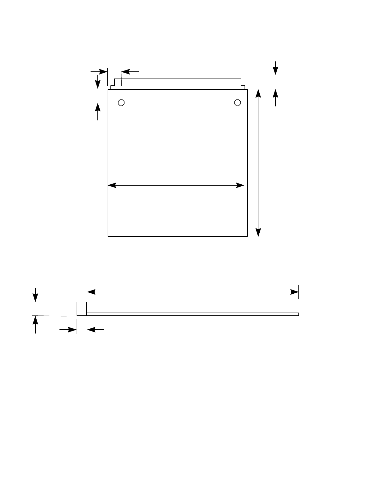
VC-20-PRJ25 IMBE™ Vocoder Board
User’s Manual
Section 4 – Technical Drawings
5.5 mm
41612 Connector
< 7.5 mm
3.0 mm
100 mm
112 mm
11 mm
(bottom view)
112 mm
(components < 12.5 mm)
(connections < 2 mm)
< 7.5 mm
(side view)
Figure 7: Vocoder Physical Dimensions
DVSI Confidential Proprietary
Page 15
Page 24

VC-20-PRJ25 IMBE™ Vocoder Board
User’s Manual
Section 5 – DVSI Support
Chapter 3 DVSI Support Services
Technical Support
If you have any problems with the VC-20-PRJ25 IMBE™ Vocoder Board or have questions about its
operation, please contact:
Digital Voice Systems, Inc.
234 Littleton Road
Westford, MA 01886 USA
Phone: (978) 392-0002
Fax: (978) 392-8866
email: info@dvsinc.com
web: www.dvsinc.com
DVSI Confidential Proprietary
Page 16
Page 25

NOTES
DVSI Confidential Proprietary
Page 17
 Loading...