

Digital Voice Systems AMBE-3000 HDK User Manual
AMBE-3000™-HDK
Development Board
Version 0.4
November 17, 2008
User’s Manual
Digital Voice Systems, Inc.
The Speech Compression Specialists

AMBE-3000™-HDK Development Board
User’s Manual
Version 0.4
November 17, 2008
Copyright, 2008
Digital Voice Systems, Inc
234 Littleton Road
Westford, MA 01886
(The most up to date version of the manual is always available at www.dvsinc.com)
This document may not, in whole or in part be copied, photocopied, reproduced, translated, or reduced
to any electronic medium or machine readable form without prior consent in writing from Digital Voice
Systems, Incorporated.
Every effort has been made to ensure the accuracy of this manual. However, Digital Voice Systems,
Inc. makes no warranties with respect to the documentation and disclaims any implied warranties of
merchantability and fitness for a particular purpose. Digital Voice Systems, Inc. shall not be liable for
any errors or for incidental or consequential damages in connection with the furnishing, performance, or
use of this manual or the examples herein. The information in this document is subject to change
without notice.
Trademarks
AMBE-3000™-HDK Development Board and AMBE-3000™ Vocoder Chip, are trademarks of Digital
Voice Systems, Inc. AMBE® is a registered trademark of Digital Voice Systems, Inc. Other product
names mentioned may be trademarks or registered trademarks of their respective companies and are
the sole property of their respective manufacturers.
All Rights Reserved
Data subject to change

AMBE-3000™-HDK Development Board
User’s Manual Version 0.4
Information – Section
AMBE-3000™-HDK Development Board END USER License Agreement
*** Important Read Carefully ***
1. Preliminary Statements and Definitions
1.1 This nonexclusive end user product license agreement is a legal
agreement between the customer (the END USER) and Digital Voice
Systems, Inc. (DVSI) covering the terms and conditions under which
DVSI's proprietary content (that may consist of and is not limited to
software, hardware, documentation and other material) is licensed to the
END USER as part of this PRODUCT.
a) The PRODUCT shall mean the Hardware, Software, Documentation
and other materials that were provided by DVSI, either directly or
indirectly through distributors or agents, to END USER as part of a sale,
delivery or other transaction.
b) Hardware can be in the form of Integrated Circuits (such as Digital
signal Processors) Circuit boards and electronics enclosed in a chassis.
DVSI’s AMBE-3003™ Vocoder Chip is an example of an Integrated
Circuit.
c) Software can be in form of computer code, firmware masked into an IC
or stored or embedded into ROM or RAM or Flash memory, or software
stored on any media (such as CD-ROM, floppy disk, hard drive, solidstate memory or the Internet)
d) Documentation means written or electronic information, including user
manuals, technical documents, training materials, specifications or
diagrams, that pertain to or are delivered with the PRODUCT in any
manner (including in print, on CD-ROM, or on-line).
1.2 DVSI has developed a number of voice coding methods and algorithms
(the “Technology”) which include DVSI’s Advanced Multi-Band Excitation
(“AMBE”) , AMBE+™, and AMBE+2™ voice coders. The Technology
codes speech at low bit rates and may include error correction, echo
cancellation and other auxiliary functions.
1.3 "DVSI Voice Compression Software" shall mean the voice coding
Software that implements or embodies the Technology and is embedded
into or otherwise provided with the PRODUCT.
1.4 "DVSI Voice Codec" shall mean the DVSI Voice Compression Software,
any PRODUCT Hardware into which the DVSI Voice Compression
Software is embedded or executed and any associated Documentation.
1.5 DVSI represents that it owns certain “Proprietary Rights” in the PRODUCT
including patent rights, copyrights, trademarks and trade secrets. These
rights include one or more of the following US Patents U.S. #6,199,037,
#5,870,405, #5,826,222, #5,754,974, #5,715,365, #5,701,390, #5,664,051,
#5,630,011, #5,581,656, #5,517,511, #5,491,772 #5,247,579, #5,226,108,
#5,226,084 #5,216,747 #5,195,166 #5,081,681, B1 #6,161,089,
#5,870,405, #5,649,050 and under other US and foreign patents and
patents pending. AMBE, AMBE+™ and AMBE+2™ are trademarks of
Digital Voice Systems, Inc.
1.6 “END USER” shall mean the person and/or organization to whom the
DVSI Vocoder Product (software or hardware) was delivered or provided to
as specified in the purchase order or other documentation. In the event
that the END USER transfers his rights under this license to a third party as
specified in Section 3.0, then this third party shall become an “END
USER”.
1.7 DVSI reserves the right to make modifications and other changes to its
products and services at any time and to discontinue any product or
service without notice.
2. License Granted
2.1 Subject to the conditions herein and upon initial use of the DVSI Product,
DVSI hereby grants to END USER a non-exclusive, limited license to use
the DVSI Voice Compression Software and Technology within the
PRODUCT. No license is granted for any use of the DVSI Voice
Compression Software or Technology on any other device or Hardware or
in any manner other than within the original unmodified PRODUCT
purchased from DVSI. No license is granted to copy or modify the DVSI
Voice Compression Software or the PRODUCT either in whole or in part.
2.2 No license, right or interest in any trademark, trade name or service mark
of DVSI is granted under this Agreement. END USER acknowledges that
the PRODUCT may contain trade secrets of DVSI, including but not limited
to the specific design, and associated interface information.
2.3 END USER shall not copy, extract, reverse engineer, disassemble, decompile or otherwise reduce the DVSI Voice Compression Software to
human-readable form. END USER shall not alter, duplicate, make copies
of, create derivative works from, distribute, disclose, provide or otherwise
make available to others, the DVSI Voice Compression Software and
Technology and/or trade secrets contained within the PRODUCT in any
form to any third party without the prior written consent of DVSI. The END
USER shall implement reasonable security measures to protect such trade
secrets.
2.4 This is a license, not a transfer of title, to the DVSI Voice Compression
Software, Technology and Documentation, and DVSI retains ownership
and title to all copies.
3. Transfer of License
3.1 The END USER shall have the right to transfer the rights under this
Agreement to a third party by either (i) providing the third party with a copy
of this Agreement or (ii) providing the third party with an agreement written
by the END USER ( hereinafter “END USER Agreement”) so long as the
END USER Agreement is approved in writing by DVSI prior to transfer of
the PRODUCT. The END USER Agreement shall contain comparable
provisions to those contained herein for protecting the Proprietary
Information from disclosure by such third party. Third parties shall agree to
accept all the terms and conditions under either Agreement or the END
USER Agreement.
4. Term and Termination
4.1 This Agreement is effective upon initial delivery of the PRODUCT and
shall remain in effect until terminated in accordance with this agreement.
4.2 This Agreement shall terminate automatically without notice from DVSI if
END USER fails to comply with any of the material terms and conditions
herein. END USER may terminate this Agreement at any time upon
written notice to DVSI certifying that END USER has complied with the
provisions of Section 3.
4.3 Upon termination of this Agreement for any reason, END USER shall: (i)
return the PRODUCT and documentation purchased or acquired, or in
Licensee’s possession, to DVSI; (ii) have no further rights to any DVSI
Software or the Technology without a separate written license from DVSI;
(iii) discontinue all use of the PRODUCT;
All confidentiality obligations of Customer and all limitations of liability and
disclaimers and restrictions of warranty shall survive termination of this
Agreement. In addition, the provisions of the sections titled "U.S.
Government End User Purchasers" and "General Terms Applicable to the
Limited Warranty Statement and End User License" shall survive
termination of this Agreement.
5. Payments
5.1 In consideration of the materials delivered as part of the Product, and in
consideration of the license granted by DVSI for the PRODUCT, and in
consideration of DVSI's performance of its obligations hereunder, the END
USER agrees to pay to DVSI the fees as specified in DVSI's invoice.
Payments of fees shall be received by DVSI prior to shipment of the
PRODUCT.
6. Proprietary Notices
6.1 END USER shall maintain and not remove any copyright or proprietary
notice on or in the PRODUCT.
6.2 Reproduction of non-proprietary information found in DVSI Users Manuals
or data sheets is permissible only if the END USER reproduces without
alteration, and includes all copyright and other proprietary notices, all
associated warranties, conditions and limitations on all copies, in any form.
7. Proprietary Information
7.1 The parties agree that the PRODUCT shall be considered Proprietary
Information.

AMBE-3000™-HDK Development Board
User’s Manual Version 0.4
Information – Section
7.2 Except as otherwise provided in this Agreement, END USER shall not
use, disclose, make, or have made any copies of the Proprietary
Information, in whole or in part, without the prior written consent of DVSI.
8. Limited Warranty
8.1 DVSI warrants the PRODUCT to be free from defects in materials and
workmanship under normal use for a period of ninety (90) days from the
date of delivery. The date of delivery is set forth on the packaging material
in which the Product is shipped. This limited warranty extends only to the
Customer who is the original purchaser. If the PRODUCT is found to be
defective and the condition is reported to DVSI, within the warranty period,
DVSI may, at its option, repair, replace, or refund of the purchase price of
the PRODUCT. DVSI may require return of the PRODUCT as a condition
to the remedy.
Restrictions. This warranty does not apply if the Product (a) has been
altered, (b) has not been installed, operated, repaired, or maintained in
accordance with instructions supplied by DVSI, (c) has been subjected to
abnormal physical or electrical stress, misuse, negligence, or accident;
8.2 Except as stated in Section 8.1, the PRODUCT is provided "as is" without
warranty of any kind. DVSI does not warrant, guarantee or make any
representations regarding the use, or the results of the use, of the
PRODUCT with respect to its correctness, accuracy, reliability, speech
quality or otherwise. The entire risk as to the results and performance of
the PRODUCT is assumed by the END USER. After expiration of the
warranty period, END USER, and not DVSI or its employees, assumes the
entire cost of any servicing, repair, replacement, or correction of the
PRODUCT.
8.3 DVSI represents that, to the best of its knowledge, it has the right to enter
into this Agreement and to grant a license to use the PRODUCT to END
USER.
8.4 Except as specifically set forth in this Section 8, DVSI makes no express
or implied warranties including, without limitation, the warranties of
merchantability or fitness for a particular purpose or arising from a course
of dealing, usage or trade practice, with respect to the PRODUCT. Some
states do not allow the exclusion of implied warranties, so the above
exclusion may not apply to END USER. No oral or written information or
advice given by DVSI or its employees shall create a warranty or in any
way increase the scope of this warranty and END USER may not rely on
any such information or advice. The limited warranties under this Section 8
give END USER specific legal rights, and END USER may have other
rights, which vary from state to state.
9. Limitation of Liability
The END USER agrees that the limitations of liability and disclaimers set
forth herein will apply regardless of whether the END USER has accepted
the product or service delivered by DVSI.
9.1 In no event shall DVSI be liable for any special, incidental, indirect or
consequential damages resulting from the use or performance of the
PRODUCT whether based on an action in contract, or for applications
assistance, or product support, or tort (including negligence) or otherwise
(including, without limitation, damages for loss of business revenue, profits,
business interruption, and loss of business information or lost or damaged
data), even if DVSI or any DVSI representative has been advised of the
possibility of such damages.
9.2 Because some states or jurisdictions do not allow the exclusion or
limitation of liability for consequential or incidental damages, the above
limitations may not apply to END USER.
9.3 DVSI's maximum liability for damages arising under this Agreement shall
be limited to 20% (twenty percent) of the fees paid by END USER for the
particular PRODUCT that gave rise to the claim or that is the subject
matter of, or is directly related to, the cause of action.
10. Taxes
10.1 All payments required under Section 4 or otherwise under this
Agreement are exclusive of taxes and END USER agrees to bear and be
responsible for the payment of all such taxes (except for taxes based upon
DVSI's income) including, but not limited to, all sales, use, rental receipt,
personal property or other taxes which may be levied or assessed in
connection with this Agreement.
11. Export
11.1 United States export laws and regulations prohibit the exportation of
certain products or technical data received from DVSI under this
Agreement to certain countries except under a special validated license.
Some of the restricted countries include: Libya, Cuba, North Korea, Iraq,
Serbia, Taliban in Afghanistan, Sudan, Burma, and Iran. The END USER
hereby gives its assurance to DVSI that it will not knowingly, unless prior
authorization is obtained from the appropriate U.S. export authority, export
or re-export, directly or indirectly to any of the restricted countries any
products or technical data received from DVSI under this Agreement in
violation of said United States Export Laws and Regulations. DVSI neither
represents that a license is not required nor that, if required, it will be
issued by the U.S. Department of Commerce. Licensee shall assume
complete and sole responsibility for obtaining any licenses required for
export purposes.
12. Governing Law
12.1 This Agreement is made under and shall be governed by and construed
in accordance with the laws of the Commonwealth of Massachusetts,
(USA), except that body of law governing conflicts of law. If any provision
of this Agreement shall be held unenforceable by a court of competent
jurisdiction, that provision shall be enforced to the maximum extent
permissible, and the remaining provisions of this Agreement shall remain
in full force and effect. This Agreement has been written in the English
language, and the parties agree that the English version will govern.

AMBE-3000™-HDK Development Board
User’s Manual Version 0.4
Information – Section
Special Handling Instructions
To avoid damage from the accumulation of a static charge, industry standard electrostatic discharge
precautions and procedures must be employed during handling and installation the AMBE-3000™-HDK
Development Board.
Read Instructions and Users Manual – All of the safe handling and operating instructions should be read
before integration of the AMBE-3000™-HDK Development Board begins. Failure to exercise reasonable
care and to follow all instructions and heed all warnings may result in injury to property or to individuals.
Retain Instructions - The handling and operating instructions should be retained for future reference.
Follow Instructions - All operating and use instructions should be followed.
Storage
To insure maximum shelf life in long term storage, AMBE-3000™-HDK Development board should be
kept in an a static shield, moisture controlled package at <40°C and <90% Relative Humidity
Installation
Ventilation - The AMBE-3000™-HDK Development Board unit should be situated so that its location or
position does not interfere with proper ventilation and air circulation around the board.
Heat - The AMBE-3000™-HDK Development Board unit should be situated away from devices that
could act as a heat source such as an amplifier.
Power Sources - The AMBE-3000™-HDK Development Board should be connected to a power source
only of the type described in this Users Manual.


AMBE-3000™-HDK Development Board
User’s Manual Version 0.4
Section – Table of Contents
Table of Contents
Preliminary
INTRODUCTION.....................................................................................1
OVERVIEW ............................................................................................................1
AMBE-3000™ HDK FEATURES ............................................................................1
AMBE-3000™ HDK DESCRIPTION........................................................................1
WHAT’S INCLUDED WITH THE HDK.........................................................................2
CONNECTORS, TEST POINTS & INDICATORS............................................3
OVERVIEW OF HDK INTERFACES ..........................................................................3
DC POWER (P5) ...................................................................................................4
USB CONNECTION ................................................................................................5
USB driver installation steps:......................................................................5
ANALOG AUDIO I/O................................................................................................6
Handset.......................................................................................................6
3.5mm Phono Jacks....................................................................................7
RS-232 CONNECTIONS .........................................................................................7
µ Controller RS-232 Connection (P2) .........................................................7
AMBE-3000™ Vocoder Chip RS-232 (P1) .................................................8
HDK LIST OF HEADERS .........................................................................................8
HDK TEST POINTS................................................................................................9
JP1 LED Indicators Test Points ..................................................................9
JP5 Header Serial Interface Test Points.....................................................9
JP7 Handset Analog Audio I/O Test Points ..............................................10
JP8 Header...............................................................................................10
HEADER CONNECTIONS.......................................................................................10
JP10 Header µController JTAG ................................................................11
HDK BOARD STATUS INDICATOR LEDS................................................................11
HDK CONFIGURATION ........................................................................13
OVERVIEW ..........................................................................................................13
BOARD RESET.....................................................................................................13
AMBE-3000™ VOCODER CHIP CONFIGURATION VIA DIP-SWITCHES.....................13
Slide Dip-Switch Settings..........................................................................14
VOCODER RATE SELECTION ................................................................................14
AMBE-3000™ UART INTERFACE BAUD RATE SELECTION...................................15
HDK CONFIGURATION JUMPERS..........................................................................15
JP2, JP4 and JP12 Headers Jumpers......................................................15
JP11 Header LED Indicators.....................................................................16
JP13 Header CODEC_Input Select..........................................................16
JP15 Header WD Disable.........................................................................16
JP11 Header USB Power..........................................................................17
OPERATION........................................................................................18
OPERATING MODES.............................................................................................18
HDK TO AMBE-3000™ VOCODER CHIP INTERFACE ............................................19
Data Pass Through...................................................................................19
HDK SOFTWARE.................................................................................................20
Installing HDK program file On Windows Vista/XP...................................20
RUNNING THE HDK CONTROL SOFTWARE............................................................21
IDLE MODE..........................................................................................................24
CODEC PLAY/RECORD MODE...............................................................................24
Play File to Audio Output...........................................................................25
Record Input Audio to File.........................................................................26
Play/Record Audio ....................................................................................28

AMBE-3000™-HDK Development Board
User’s Manual Version 0.4
Section – Table of Contents
PACKET MODE....................................................................................................29
Decode File...............................................................................................31
LOOPBACK MODE...............................................................................................34
LoopBack Mode using the AMBE-3000™ Vocoder chip’s Parallel Interface.
..................................................................................................................34
LoopBack Mode using the AMBE-3000™ Vocoder chip’s UART Interface35
A3KDIRECT MODE...............................................................................................36
DUAL HDK MODE (FULL DUPLEX)........................................................................37
Full Duplex Communication Setup and Control........................................38
“HDK UART” DATA PACKET STRUCTURE ............................................................41
DOCUMENTATION & SOFTWARE DEVELOPMENT ....................................42
DOCUMENTATION................................................................................................42
SOFTWARE.........................................................................................................42
THIRD PARTY TOOLS...........................................................................................42
SPECIFICATIONS.................................................................................43
OVERVIEW..........................................................................................................43
BOARD CONNECTIONS ........................................................................................43
AUDIO I/O CONNECTIONS....................................................................................44
HEADER CONNECTIONS.......................................................................................45
ELECTRICAL INPUT..............................................................................................45
MECHANICAL ......................................................................................................45
APPENDIX..........................................................................................46
RATE TABLES .....................................................................................................46
MSP430 INPUT/OUTPUT PIN DESCRIPTION..........................................................50
SOFTWARE DEVELOPMENT..................................................................................50
Additional Reference Material...................................................................51
SUPPORT ..........................................................................................52
DVSI CONTACT INFORMATION.............................................................................52
TABLE OF REVISIONS ..........................................................................................53
List of Tables
TABLE 1 HDK CONNECTORS .................................................................................................4
TABLE 2 HDK LIST OF HEADERS............................................................................................9
TABLE 3 HEADER TEST POINTS .............................................................................................9
TABLE 4 JP1 TEST POINTS....................................................................................................9
TABLE 5 JP5 SERIAL TEST POINTS ......................................................................................10
TABLE 6 HEADER I/O TEST POINTS......................................................................................10
TABLE 7 JP8 SERIAL DATA ..................................................................................................10
TABLE 8 HEADER CONNECTIONS..........................................................................................11
TABLE 9 JP10 MSP430 JTAG............................................................................................11
TABLE 10 BOARD STATUS LED'S.........................................................................................12
TABLE 11 BOARD DIP SWITCHES .........................................................................................14
TABLE 12 AMBE-3000™ UART BAUD RATE SELECTION .....................................................15
TABLE 13 JUMPER HEADER CONNECTORS ...........................................................................15
TABLE 14 JP2 TO JP4 HEADER JUMPERS ............................................................................16
TABLE 15 JP11 ENABLE LED INDICATORS ...........................................................................16
TABLE 16 JP13 CODEC INPUT SELECTION ...........................................................................16
TABLE 17 JP15 WD DISABLE ..............................................................................................16
TABLE 18 JP16 USB 5 VOLT POWER ..................................................................................17
TABLE 19 HDK MODES .......................................................................................................18
TABLE 20 HDK AMBE-3000™ INTERFACES ........................................................................19
TABLE 21 STANDARD RATE TABLE FOR AMBE-3000™........................................................47

AMBE-3000™-HDK Development Board
User’s Manual Version 0.4
Section – Table of Contents
List of Figures
FIGURE 1 BASIC BLOCK DIAGRAM OF THE AMBE-3000™ HDK BOARD ....................................3
FIGURE 2 BOARD CONNECTIONS............................................................................................4
FIGURE 3 POWER INPUT CONNECTION....................................................................................4
FIGURE 4 USB CONNECTOR ..................................................................................................5
FIGURE 5 WINDOWS DEVICE MANAGER..................................................................................6
FIGURE 6 AUDIO CONNECTIONS .............................................................................................6
FIGURE 7 RS-232 SERIAL CONNECTIONS...............................................................................7
FIGURE 8 HEADER TEST POINTS, CONNECTIONS AND JUMPERS ..............................................8
FIGURE 9 LEDS...................................................................................................................11
FIGURE 10 RESET SWITCH...................................................................................................13
FIGURE 11 VOCODER SETTINGS SWITCHES SW1 AND SW2.................................................14
FIGURE 12 PLAY / RECORD -PLAY BLOCK DIAGRAM ..............................................................25
FIGURE 13 PLAY / RECORD -RECORD BLOCK DIAGRAM .........................................................26
FIGURE 14 PLAY / RECORD -PLAYRECORD BLOCK DIAGRAM..................................................28
FIGURE 15 PACKET MODE –ENC PPT INTERFACE BLOCK DIAGRAM.......................................30
FIGURE 16 PACKET MODE -ENC UART INTERFACE BLOCK DIAGRAM .....................................30
FIGURE 17 PACKET MODE -DEC PPT INTERFACE BLOCK DIAGRAM........................................32
FIGURE 18 PACKET MODE -DEC UART INTERFACE BLOCK DIAGRAM .....................................32
FIGURE 19 PACKET MODE ENCODE/DECODE PPT INTERFACE BLOCK DIAGRAM ....................33
FIGURE 20 PACKET MODE UART INTERFACE BLOCK DIAGRAM .............................................34
FIGURE 21 LOOPBACK PPT MODE AMBE-3000™ VOCODER CHIP (PARALLEL INTERFACE)...35
FIGURE 22 LOOPBACK UART MODE AMBE-3000™ VOCODER CHIP (UART INTERFACE) .....35
FIGURE 23 FULL DUPLEX MODE...........................................................................................38
FIGURE 24 TWO HDK BOARDS CONNECTED TOGETHER.........................................................40
FIGURE 25 RS-232 NULL MODEM CABLE PIN-OUT................................................................40
FIGURE 26 RS-232 STRAIGHT THROUGH CABLE PIN-OUT......................................................41


AMBE-3000™-HDK Development Board
User’s Manual Version 0.4
Page 1
DVSI Confidential Proprietary
Section 1 – Introduction
Introduction
Overview
The Digital Voice Systems, Inc. (DVSI) AMBE-3000™-HDK Development Board is a comprehensive,
evaluation, test and development platform that helps product designers and manufacturing engineers
gain experience with the low-bit-rate AMBE-3000™ Vocoder Chip. The AMBE-3000™ HDK is ideal for
comparing voice quality at various rates, analyzing the compressed voice data I/O stream and
establishing interface requirements. This valuable knowledge gives engineers the insight required to
start prototyping their own low-bit-rate communication systems quickly and easily thereby decreasing
development costs and speeding up a new product’s time to market.
The AMBE-3000™ HDK employs DVSI’s AMBE-3000™ vocoder chip that is ideal in communication
systems, including push-to-talk land mobile radio, satellite and wireless telephony. The AMBE-3000™
Vocoder Chip contains proprietary software that implements the Advanced Multi-Band Excitation
AMBE® voice compression algorithm. The AMBE-3000™ Vocoder Chip is capable of data rates
containing compressed speech and FEC data from 2.0 Kbps to 9.6 Kbps (in 50 bps increments),. This
data rate flexibility makes the AMBE-3000™ HDK a cost efficient design and development tool for high
performance, low bandwidth voice communication applications.
AMBE-3000™ HDK Features
• The AMBE®+2 Vocoder with high quality speech compression and FEC data rates that can be
set from 2000 bps to 9600 bps.
• The development kit includes: circuit design details, sample control software and reference
documentation.
• The HDK is equipped with a AIC14 codec to provide an analog audio I/O interface
• Vocoder and hardware configuration via dipswitches, jumpers and USB to PC interface.
• Encode and decode files to/from a PC through the USB interface.
• Real-time full-duplex communication between two HDK boards using the RS-232 and the analog
2-wire or 4-wire audio interface.
• Full Control of AMBE-3000™ Vocoder Chip advanced capabilities such as Soft decision FEC,
Voice Activity Detection (VAD), adaptive Comfort Noise Insertion (CNI) and DTMF tones.
• Low power requirements allow the board to be powered with only a 5 Volt DC power adapter.
AMBE-3000™ HDK Description
The AMBE- 3000™ HDK is a completely functional system from the analog audio interface to the digital
channel interface. The straightforward design of the board provides a variety of user interfaces and test
points that allow designers to rapidly prototype their own AMBE-3000™ designs.
Digital Voice Systems’ AMBE-3000™ Vocoder Chip is the core of the AMBE-3000™ HDK. All of the
supporting chips on the board were chosen for their low cost, ease of use and wide availability. The
control, I/O and timing of the board are handled by the Texas Instruments MSP430 microprocessor unit
(MCU). The MSP-430 flash image is easily programmed using an MSP430-FET serial programmer a
low cost development tool from Texas Instruments.
The AMBE-3000™ HDK is also a stand-alone voice processing board, equipped with connections for
analog audio I/O, a RS-232 serial UART port communication channel interface, and a RS-232 packet
interface port.
The AMBE-3000™ HDK can demonstrate the capabilities and benefits of the AMBE-3000™ vocoder
chip in real time, without investing much time in engineering and product development. Once a new
Digital Voice Systems, Inc.
The Speech Compression Specialists

AMBE-3000™-HDK Development Board
User’s Manual Version 0.4
Page 2
DVSI Confidential Proprietary
Section 1 – Introduction
product design is complete and manufacturing begins the AMBE-3000™ HDK can then be used to
simulate actual system conditions as a quality control reference standard. Additionally, the HDK can be
used to batch process files for evaluation of the vocoder.
What’s Included with the HDK
The development kit includes the following items:
HDK evaluation board
Power Adapter (120v AC to 5 V DC)
Handset with cord
AMBE-3000™ HDK CD (The most up to date version of the manual is always available at
www.dvsinc.com/brochures/literature.htm)
The AMBE-3000™ HDK CD contains the AMBE-3000™ User’s Manual, program source code for the on
board microprocessor (MSP430) (see Note) and a PC executable (with source) for interfacing the HDK
with a PC, as well as a full set of schematics, reference designs and test vectors.
Note: The development tools for the MSP430 MCU are widely available and easily obtained from Texas
Instruments and various sources on the web. This gives designers an opportunity to recompile the code
to test other configurations. The main tool tree is Code Composer Essentials. This allows for a robust
development environment free of cost (up to 16Kb).
AMBE-3000™-HDK Development Board
User’s Manual Version 0.4
Page 3
DVSI Confidential Proprietary
Section 2 – Connectors, Test Points & Indicators
Connectors, Test Points & Indicators
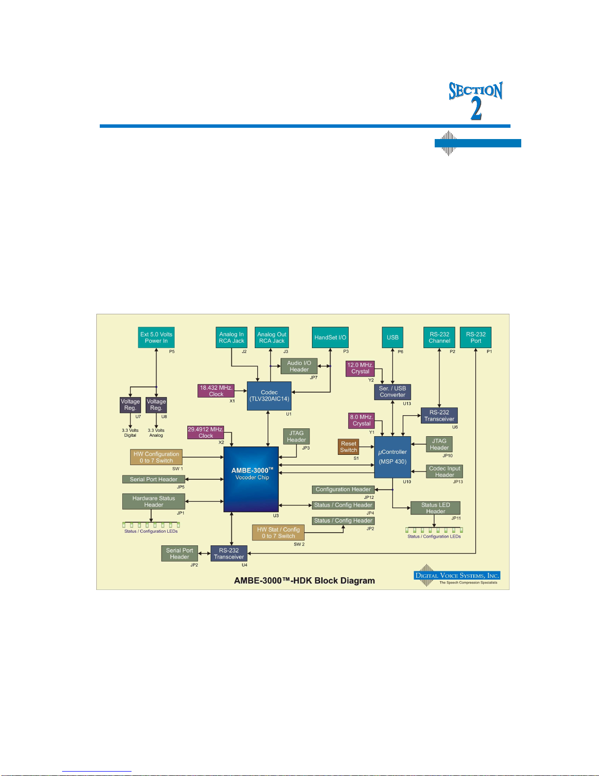
Overview of HDK Interfaces
The AMBE-3000™ HDK is designed with flexibility in mind. It provides a variety of interfaces that allow
for fast and easy integration and testing.
The AMBE-3000™-HDK can be used as a standalone development tool or, be connected to another
AMBE-3000™-HDK via the RS-232 channel interface to demonstrate its capabilities as a full-duplex
real-time communication system.
With a PC the board can encode speech data from the handset, 3.5mm stereo jack (Line In) input
connections, or it can process speech files from a PC (USB connection). When connecting two boards
together the RS-232 interface acts as the channel for the compressed voice serial data bit stream. The
RS-232 Channel I / O is an asynchronous serial interface that uses a protocol designed by DVSI.
Figure 1 Basic block diagram of the AMBE-3000™ HDK board
Digital Voice Systems, Inc.
The Speech Compre ssion Specialists
AMBE-3000™-HDK Development Board
User’s Manual Version 0.4
Page 4
DVSI Confidential Proprietary
Section 2 – Connectors, Test Points & Indicators
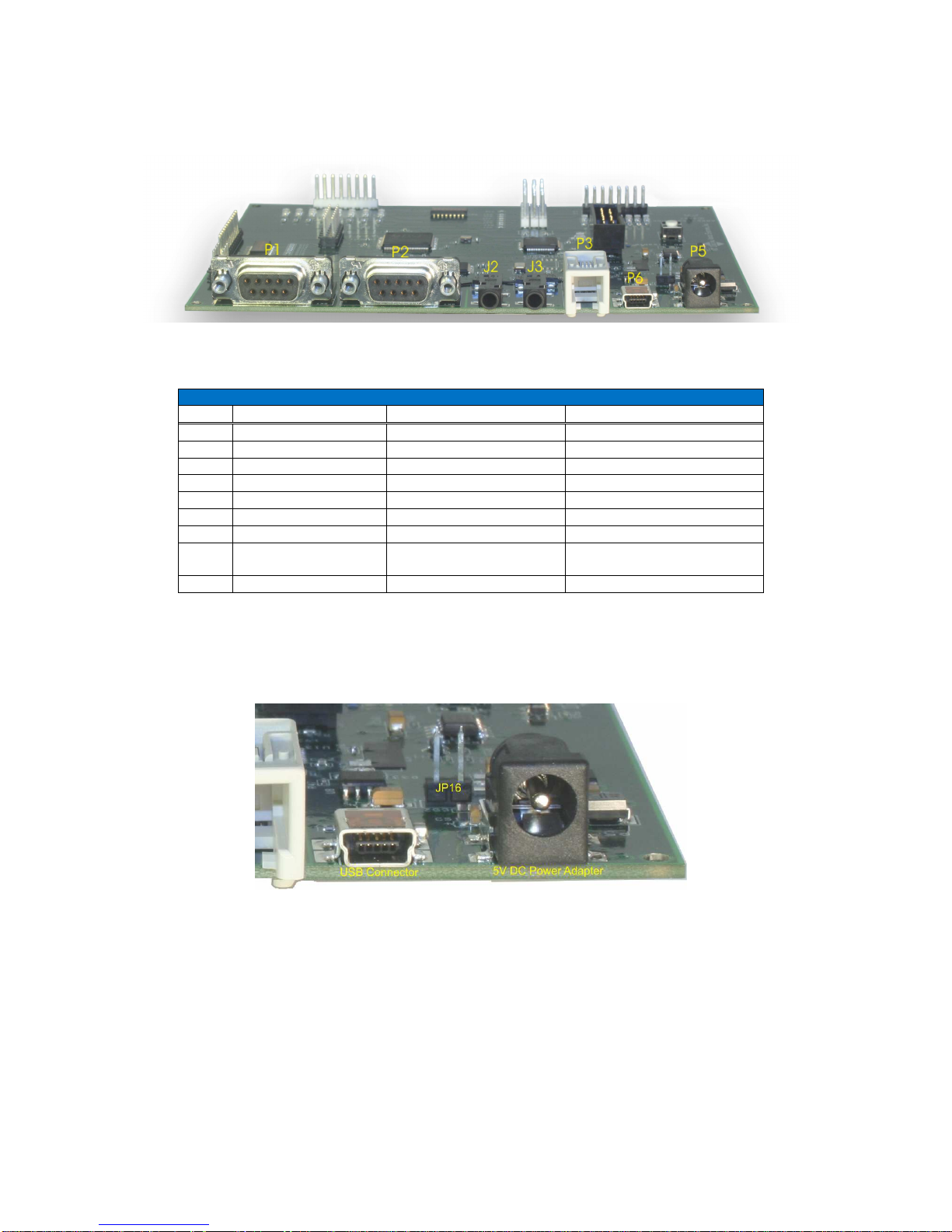
Figure 2 Board Connections
Board Connections0
Item Name Connector Type Description
P5 DC Line In Power Receptacle 5 Volts DC
P6 USB Mini USB B SMT PC Connection
P3 Handset RJ-11 Full Duplex Communication
J3 Audio Output Phono Plug Headset/Speakers
J2 Audio Input Phono Plug Microphone
P2 Serial Port DB-9s Packet Data (to/from MSP)
P1 Serial Port DB-9s
Packet Data (to/from AMBE3000™ Vocoder Chip)
Table 1 HDK Connectors
DC Power (P5)
Figure 3 Power Input Connection
The AMBE-3000™-HDK Development Board operates with a 5.0 V DC power supply. Simply plug in the
120 V AC to 5.0 V DC (~250ma) power source (provided with the HKD) into an AC power source and the
DC power receptacle (P5)
AMBE-3000™-HDK Development Board
User’s Manual Version 0.4
Page 5
DVSI Confidential Proprietary
Section 2 – Connectors, Test Points & Indicators
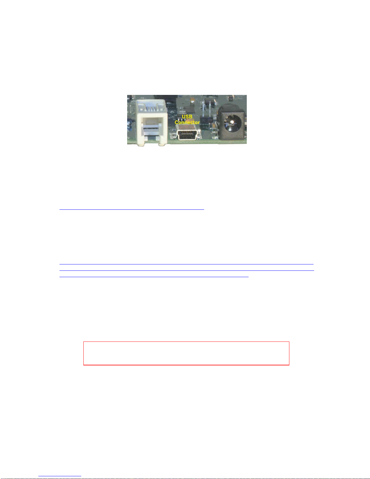
USB Connection
The USB 2 connection on the AMBE-3000™ HDK provides system setup, mode of operation and file I/O
via PC.
Figure 4 USB Connector
Control and operation of the HDK Board is done through the USB interface. To connect the AMBE3000™ HDK to a PC’s USB port, a USB “Type A to Mini-B” cable is required (included with the HDK). To
use the USB interface it is first necessary to install a USB driver.
The AMBE-3000™ HDK Board requires the TUSB3410/5052 device driver available from Texas
Instruments. TI’s USB driver is easy to install and is available to download from TI’s website
http://focus.ti.com/docs/toolsw/folders/print/tusbwinvcp.html It is a Microsoft WHQL Certified VCP driver
for Windows XP and VISTA.
USB driver installation steps:
Step 1 Go to the link above and download the USB Driver (swrc094.zip (13MB)) this file contains
TUSBWINVCP_WDF-Single_Driver_v1-2.exe. Note in order to download the file you must be a “my.ti”
registered user. Visit
https://myportal.ti.com/portal/dt?lt=myti&provider=TIPassLoginSingleContainer&goto=http%3A//focus.ti.c
om/general/docs/interimdownload.jsp%3Fdest_url%3Dhttp%253A//focus.ti.com/general/docs/lit/getliterat
ure.tsp%253FbaseLiteratureNumber%253Dswrc094%2526fileType%253Dzip for registration and login
information.
Step 2 Create a folder on your C:\ named HDK
Step 3 Unzip the swrc094.zip file to this folder and run the setup.exe program to install the driver.
Step 4 Once the driver is installed the HDK Board can be connected to the PC via USB.
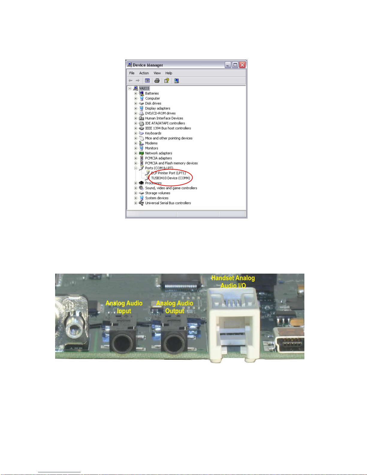
Step 5 Verify the driver is installed and working by checking what COM port it has been assigned.
To find this information use Windows “Device Manager“. To open Windows “Device Manager“
- Click Start, click Run, and then type "devmgmt.msc" (without the quotation marks).
NOTE: When using the USB Interface, connecting more than one HDK board to
the same PC at the same time could result in a MSWindows fault. Therefore it is
recommended to connect only one HDK to a PC at a time.
AMBE-3000™-HDK Development Board
User’s Manual Version 0.4
Page 6
DVSI Confidential Proprietary
Section 2 – Connectors, Test Points & Indicators
Figure 5 Windows Device Manager
Note Write down the Com Port that is being used for the TUSB3410, this value will be required to run the
HDK control program. In Figure 5 the COM port is shown as COM4.
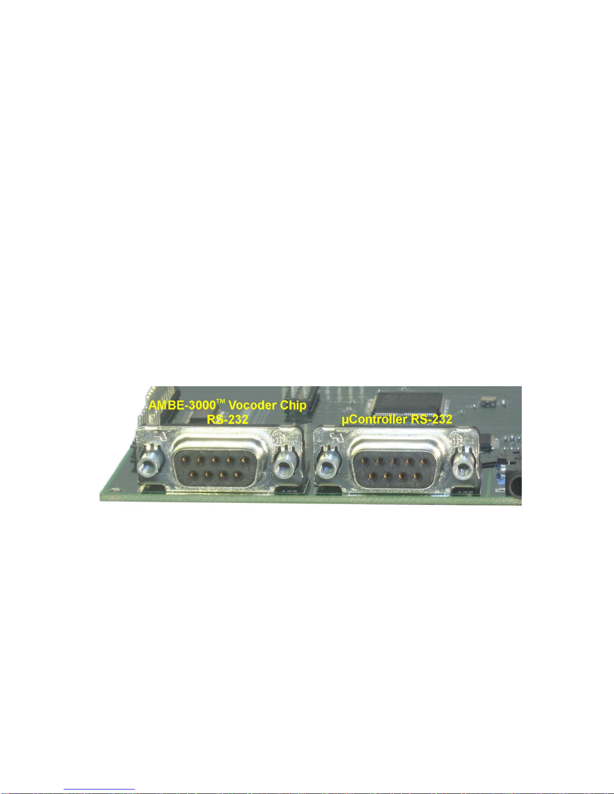
Analog Audio I/O
Figure 6 Audio Connections
Handset
If a handset is used instead of the 2 wire interface, use a standard telephone handset to connect to the
RJ11 handset connector. Be sure that the handset cord is less than 12 inches long (included in the
optional accessories kit) when not stretched. This will help reduce noise from being introduced into the
AMBE-3000™-HDK Development Board
User’s Manual Version 0.4
Page 7
DVSI Confidential Proprietary
Section 2 – Connectors, Test Points & Indicators
voice signal. The AMBE-3000™-HDK Development Board always outputs the audio to both the 4-Wire
and Handset output regardless of which voice source is selected.
3.5mm Phono Jacks
The AMBE-3000™-HDK Development Board provides two 3.5 mm phono jacks (see Figure 6 Audio
Connections) for the input and output of analog mono audio. A typical analog audio input connection for
the HDK would be to connect the audio Line output of an audio component such as, a Digital Tape,
player or even a PC sound card output to the Analog Input jack (audio cables not included) of the AMBE3000™-HDK Development Board. The AMBE-3000™-HDK Development Board outputs the analog
signal on the output phono jack that may be connected to an amplifier or Audio In jack on a PC sound
card. The unit always outputs the audio to both the 4-Wire and Handset output regardless of the voice
source selected.
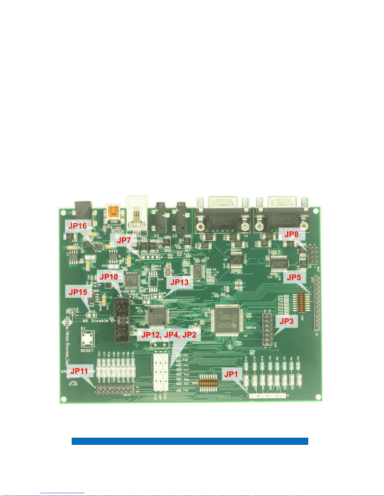
RS-232 Connections
There are two RS-232 I/O connections on the HDK board. (see Figure 7 RS-232 Serial Connections)
Connector P2 (µ-controller RS-232) is the Input/Output that can be connected to the HDK’s P1
connector using a null modem jumper cable to utilize the AMBE-3000™ Vocoder Chip’s UART Interface.
Alternatively, the P2 connector can be used to communicate to another HDK board’s P2 connector for
full duplex communications between two HDKs. This interface transfers data to/from the MSP
µcontroller. The second serial port Connector P1 (AMBE-3000™ Vocoder Chip RS-232) on the HDK
connects directly to/from the UART interface of the AMBE-3000™ Vocoder Chip.
Figure 7 RS-232 Serial Connections
µ Controller RS-232 Connection (P2)
The P2 connection on the HDK Board is an asynchronous RS-232 interface for connecting directly to a
serial device or another HDK Board. The P2 connector is connected to the µ-controller on the HDK. To
connect the µ-controller to the UART Interface of the AMBE-3000™ Vocoder Chip a null modem serial
cable is used between P1 and P2.
To connect two HDK boards together the device must be put into “Dual-HDK Mode” and P2 of one board
is connected to P2 of the other board using a Straight Through Serial Cable. When two HDK boards are
connected together to communicate, each converts the input analog speech into digital speech samples,
encodes the speech using the selected vocoder rate and then sends the compressed bit stream out as
serial data packets over the RS-232 interface. Simultaneously, the compressed bit stream from the
other HDK are read in from the RS-232 interface and decoded back into digital speech samples. The
decoded samples are converted back into analog speech via the codec whose output is sent to both the
handset and RCA line-level output connections.
AMBE-3000™-HDK Development Board
User’s Manual Version 0.4
Page 8
DVSI Confidential Proprietary
Section 2 – Connectors, Test Points & Indicators
AMBE-3000™ Vocoder Chip RS-232 (P1)
The RS-232 Packet interface (P1) is connected to the UART interface of the AMBE-3000™ Vocoder
chip (see AMBE-3000™ User’s Manual section 2.5.2). The UART signals of the AMBE-3000™ are put
through a RS-232 receiver/driver so that the user can connect directly to a terminal or terminal emulator
on a personal computer. To set up this connection plug a RS-232 cable into the P1 connector on the
HDK and plug the other end into your terminal (or one of the serial ports on your PC if you are using an
emulator) and set the terminal up for 115,200 baud, eight bits, no parity, one stop bit, and no flow
control. When using this interface in “UART Loopback Mode” a jumper cable must be connected
between P1 and P2.
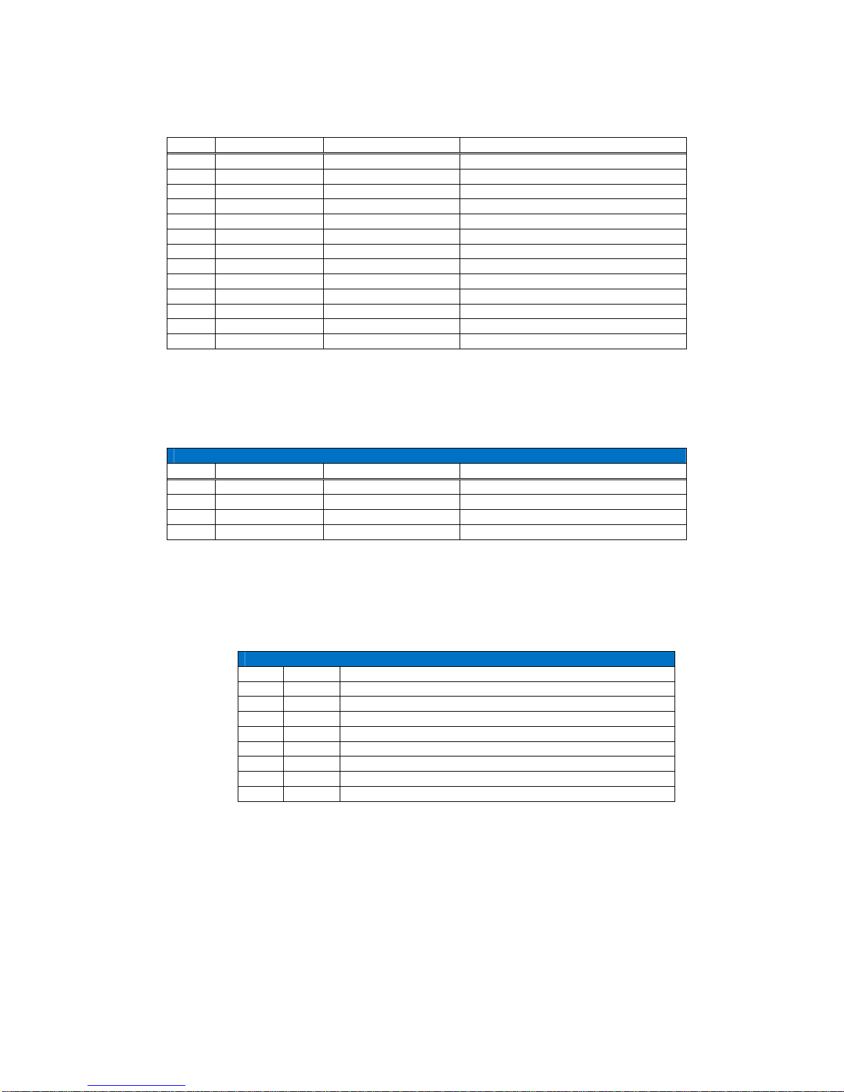
HDK List of Headers
The HDK provides a variety of Headers, connections and jumpers (see Figure 8 Header Test Points,
Connections and Jumpers).
Figure 8 Header Test Points, Connections and Jumpers
HDK Headers
AMBE-3000™-HDK Development Board
User’s Manual Version 0.4
Page 9
DVSI Confidential Proprietary
Section 2 – Connectors, Test Points & Indicators
Item Header # of Pins Name Description
JP1 Header 8x1 LED Indicators HDK board status indicators
JP2 Header 8x1 HDK Configuration Jumpers to set board options
JP3 ---- ---- Not Used
JP4 Header 8x1 HDK Configuration Jumpers to set board options
JP5 Header 2x1 Serial Data AMBE-3000™ Chip Serial I/O
JP7 Header 4x1 ---- N/A
JP8 Header 7x2 UART Output of the UART
JP10 Header 7x2 JTAG Connection for the µ controller
JP11 Header 8x2 µ controller LED’s HDK board status indicators
JP12 Header 8x1 HDK Configuration Jumpers to set board options
JP13 Header 2x1 Codec Input Select Sets Codec selection
JP15 Header 2x1 WatchDog N/A
JP16 Header 2x1 USB Power Not Used
Table 2 HDK List of Headers
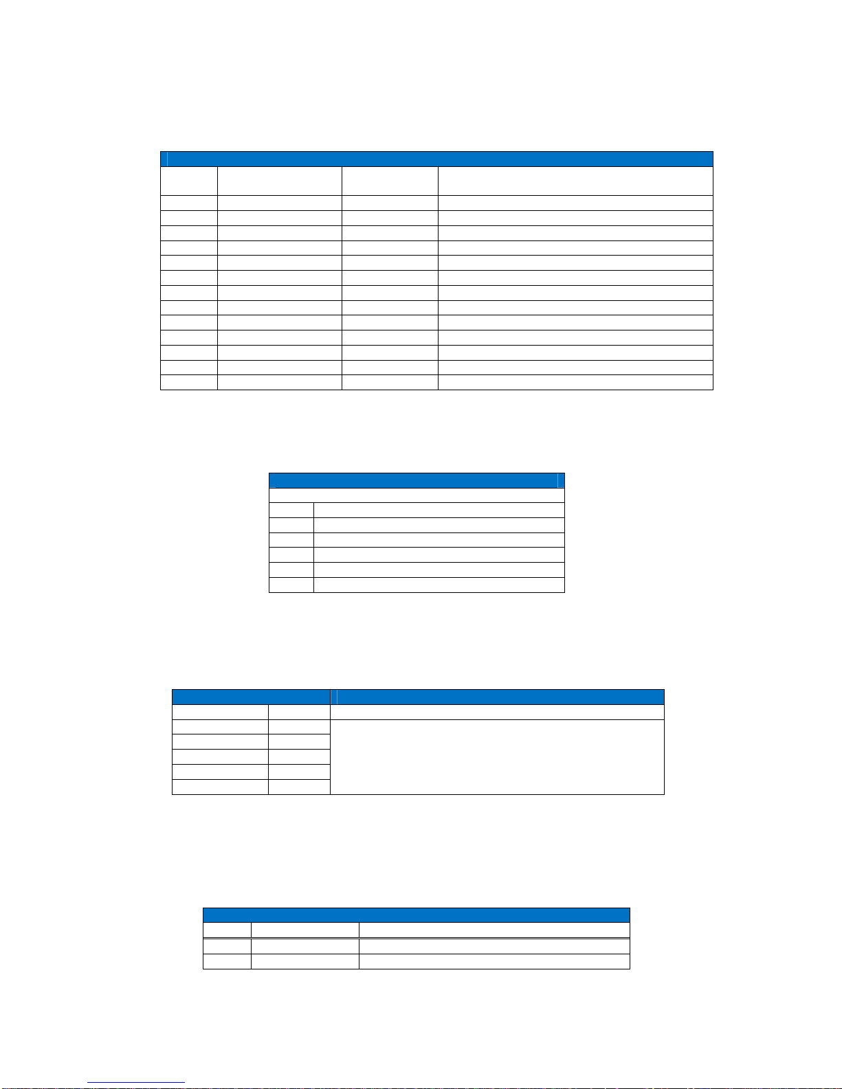
HDK Test Points
HDK Board Header Test Points
Item Header # of Pins Name Description
JP1 Header 8x1 LED Indicators HDK board status indicators
JP5 Header 2x1 Serial Data AMBE-3000™ Chip Serial I/O
JP7 ---- Handset IO N/A
JP8 Header 7x2 UART Output of the UART
Table 3 Header Test Points
JP1 LED Indicators Test Points
The JP1 Test points allow for monitoring of the status indicator LED’s as described in Table 4 JP1 Test
Points
JP1 Header
Pin Signal Description
1 STAT7 Idle Indication
2 STAT6 Standby indication
3 STAT5 Reserved
4 STAT4 Reserved
5 STAT3 Run
6 STAT2 Reserved
7 STAT1 Reserved
8 STAT0 Reserved
Table 4 JP1 Test Points
JP5 Header Serial Interface Test Points
The JP5 Header provides access to the AMBE-3000™ Vocoder chip’s Multichannel Buffered Serial Port
(McBSP) Interface. When the HDK is in Codec Mode the McBSP interface is used for speech data and
it is not available for packet data. In Packet Mode the McBSP interface is used for both speech data and
packet data.
AMBE-3000™-HDK Development Board
User’s Manual Version 0.4
Page 10
DVSI Confidential Proprietary
Section 2 – Connectors, Test Points & Indicators
JP5 Header
Pins HDK Signal Name AMBE-3000™
Pin Number
AMBE-3000™ Signal Description
1 SER_CHAN_TxD 19 Serial Transmit Data Output
2 GND Ground
3 SER_CHAN_RxD 18 Serial Receive Data Input to the AMBE-3000™
4 GND Ground
5 SER_CHAN_CLKR 21 Serial Receive Clock Input
6 SER_CHAN_CLKX 23 Serial Transmit Clock Output
7 GND Ground
8 SER_CHAN_FSR 24 Serial Receive Frame Input
9 SER_CHAN_FSX 22 Serial Transmit Frame Output
10 GND Ground
11 GND Ground
12 GND Ground
Table 5 JP5 Serial Test Points
JP7 Handset Analog Audio I/O Test Points
Handset I/O Test Points
Pin # Signal Description
1 Connected to Ground
2 Analog Out P1
3 Speaker Out
4 Microphone In/DC Microphone Bias out
Table 6 Header I/O Test Points
JP8 Header
JP8 Header
Pins Signal Signal Description
1
5
2, 3, 4, 6, 7, 8
Not Used
Table 7 JP8 Serial Data
Header Connections
HDK Board Header Connections
Item Header # of Pins Description
JP3 Header 7x2 Reserved
JP10 Header 7x2 JTAG Connection for the µ controller
 Loading...