

Page 1
234 Littleton Road Tel: (978) 392-0002 email: info@dvsinc.com
Digital Voice Systems, Inc.
The Speech Compression Specialists
Westford, MA 01886 USA Fax: (978) 392-8866 www.dvsinc.com
Using DVSI’s AMBE-2000™ and AMBE-2020™ Vocoder Chips with the
Texas Instruments’ TLV320AIC10 General Purpose CODEC
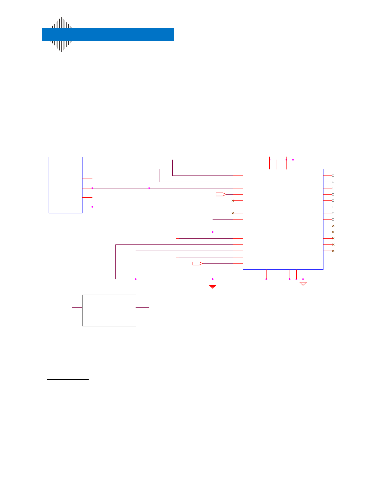
The Texas Instruments’ TLV320AIC10 codec presents a simple low cost solution for use with
DVSI’s AMBE-2000™ or AMBE-2020™ vocoder chips. This application note provides
information on interfacing these components. Figure 1 shows a sample block diagram interface,
between the TLV320AIC10 codec and DVSI’s AMBE-2000™ vocoder chip.
U1
CODEC_RX_DATA
CODEC_TX_DATA
CODEC_TX_CLK
CODEC_RX_CLK
CODEC_RX_STRB
CODEC_TX_STRB
AMBE-2000
31
41
33
27
29
37
VDD
VDD
VOICE_*RESET
16.384 MHz
16
17
19
20
21
22
23
24
25
26
27
10
11
12
13
U27
DOUT
DIN
SCLK
MCLK
FSD
FS
FLAG
FC
DCSI
ALTIN
M/*S
M0
M1
*PWRDWN
*RESET
29
VDD
DVSS
15
DVDD1
14
30
DVDD2
DVSS
AVDD
45
34
AVDD1
AVSS
AVSS
334042
AVDD2
AVSS
AVSS
46
AURXCP
AURXM
AURXFP
INM
INP
OUTM
OUTP
VMID
FILT
DTXIM
DTXIP
DTXOM
DTXOP
TLV320AIC10
3
2
1
48
47
9
8
43
38
7
6
5
4
CODEC Configuration
SERIAL
DATA
*SEE DETAIL
BELOW
SCLK
Figure 1: AMBE-2000™ and TLV320AIC10 sample block diagram
Configuration:
To configure the AMBE-2000™ for operation with the TLV320AIC10, set the CODEC_SEL
pins on the AMBE-2000™ vocoder chip to work with a generic 16 bit linear 8 kHz codec as
follows:
Interfacing AMBE-2000™ and AMBE-2020™ Vocoder Chips with TI’s TLV320AIC10 CODEC Rev 1 Oct ‘02
CODEC_SEL [1-0] (pins 85,84) = 00b
page 1 of 4
Page 2
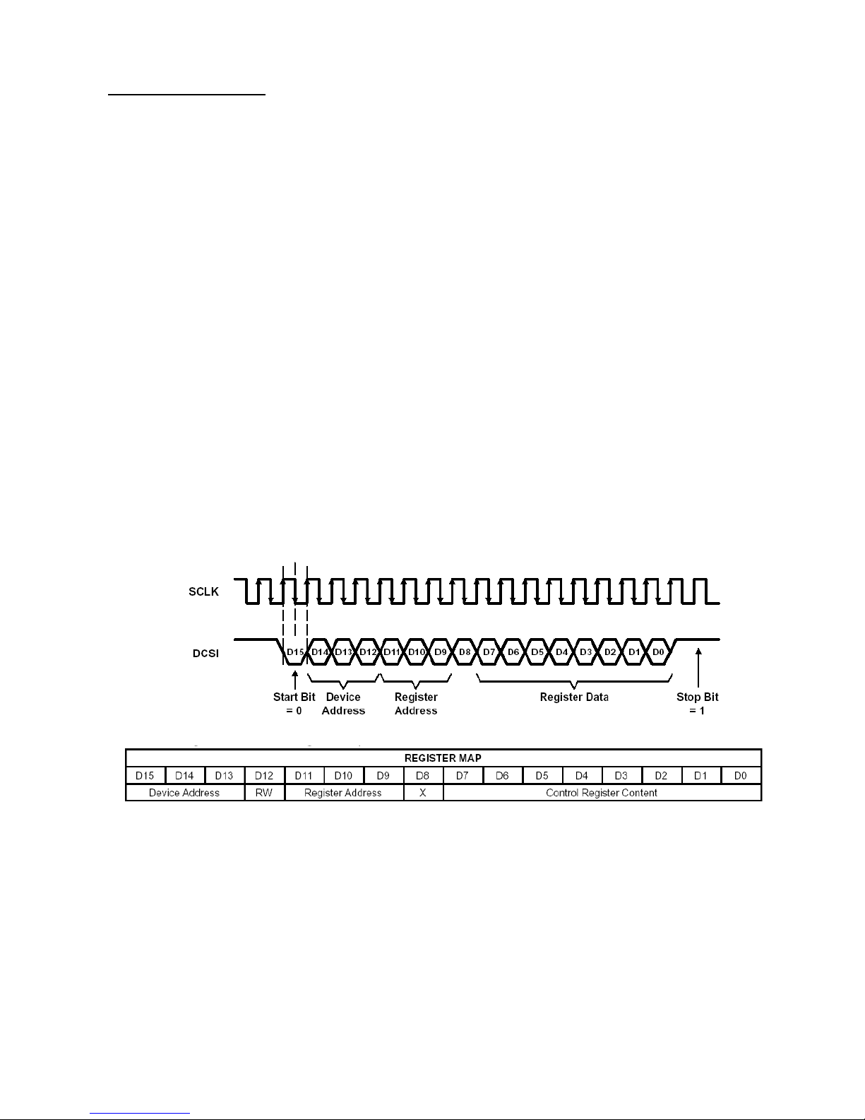
Initialization Procedure:
The control registers in the TLV320AIC10 codec must be initialized for proper operation.
The recommended procedure is to initialize the TLV320AIC10 by writing data to its 4 control
registers through the DCSI port, while the AMBE-2000™ is held in reset. The timing for the
DCSI port is shown in Figure 2.
Note that the Device Address (D14-D12) is normally set to 0 unless multiple codec devices
are used in cascade. Be sure that the stop bit is at least 2 clock pulses long between data
words as shown in the timing diagram. Shift the control words into the device 1 bit at a time
at the rate of SCLK.
Various configuration data can be used to control the operation of the TLV320AIC10 codec
(see the data sheet for more information), however for reference the AMBE-2000™ has
been tested with the TLV320AIC10 configured using the register values shown in Table 1.
Once the TLV320AIC10 is configured, the AMBE-2000™ should be taken out of reset to
begin communication with the codec.
The logic connected to the DCSI port does not have to be disabled. The user can make
adjustments to the configuration as needed (for example ADC and DAC gain). A reset to
the TLV320AIC10 codec will reset all of the internal registers. As a result, the TLV320AIC10
must be reconfigured following a reset.
Figure 2: TLV320AIC10 configuration timing via DCSI port
Interfacing AMBE-2000™ and AMBE-2020™ Vocoder Chips with TI’s TLV320AIC10 CODEC Rev 1 Oct ‘02
page 2 of 4
Page 3

Register Address
(D11-D9)
0x1 0x11
0x2 0x08
0x3 0x01
0x4 0x00
CNTL_DATA [15:0]
AIC_LOAD
SCLK
Configuration Data
(D7-D0)
Notes:
D4=1: select AUXP AND AUXM for ADC
(Handset) D5=0: enable antialiasing filter
D0=1: select 16 BIT data Format for DAC
D7=0: select normal Operation
D4-D0=8: set Frequency Divider N=8
D7-D6=0: default operation
D0=1: 16-Bit data format for ADC
D7-D4=0: ADC input gain = 0 dB
D3-D0=0: DAC output gain = 0 dB
Gain values can be adjusted as needed.
Table 1: Recommended TLV320AIC10 Configuration Data
D_IN [15:0]
LOAD
LS_IN
CLK_EN
CLK
SHIFT
Serial Out
AIC_CTRL
VDD
CE
CLK
COUNT
CLR
Q0
Q1
Q2
Q3
U5A
1 2
U6A
1 2
U8A
1 2
U7A
1 2
2
U9
3
4
5
AND4
Figure 3: TLV320AIC10 Codec Configuration Detail
Reference Materials
:
AMBE-2000™ or AMBE-2020™ Vocoder chips Users Manual:
http://www.dvsinc.com/literature.htm
TLV320AIC10 Data Sheet:
http://www-s.ti.com/sc/ds/tlv320aic10.pdf
TLV320AIC10 EVM User’s Guide:
http://www-s.ti.com/sc/psheets/slwu003d/slwu003d.pdf
Application Report – Understanding Data Converters:
http://www-s.ti.com/sc/psheets/slaa013/slaa013.pdf
1
AIC_LOAD
Interfacing AMBE-2000™ and AMBE-2020™ Vocoder Chips with TI’s TLV320AIC10 CODEC Rev 1 Oct ‘02
page 3 of 4
Page 4

TLV320AIC10 Reference Schematic (Analog Section)
TLV320AIC10 1
Analog
A
12Tuesday, October 01, 2002
Title
Size Document Number Rev
Date: Sheet
of
R12
220K
R4
100K
R6
20K
R14
4.7K
+
-
U1A
AD8544
3
2
1
411
C1
820pF
R1
10K
3.3VA
C4
2 nF
C3
200pF
R13
5.6K
R5
10K
R8
10K
3.3VA
R15
10K
R11
10K
R7
220
R9
10K
+
C5
10uF
+
C7
10uF
+
C9
10uF
3VA
C6
0.1uF
+
C8
10uF
+
C2
10uF
3.3VA
J1
Handset
2
3
1
4
2
3
1
4
R3
100K
+
-
U1B
5
6
7
R2
20K
R10
10K
VMID
AURXFP
VOICEOUTM
AURXCP
VOICEOUTP
AURXM
page 4 of 4
Interfacing AMBE-2000™ and AMBE-2020™ Vocoder Chips with TI’s TLV320AIC10 CODEC Rev 1 Oct ‘02
 Loading...