

Page 1
User's Manual
Device:
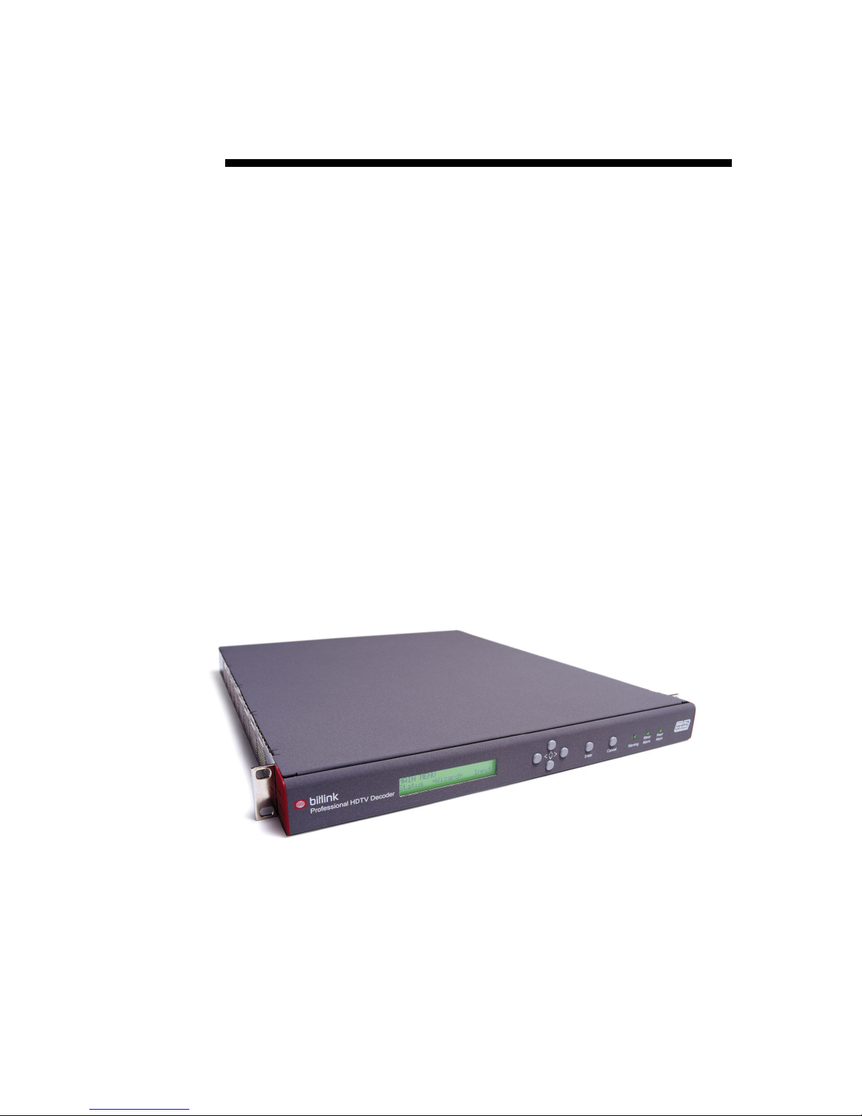
BitLink Professional HDTV
Decoder
Version:
1.1
Date:
31-October-2003
By Digital Vision
Part no.: DV-TM081001
Page 2

Head Office
Digital Vision AB
Solna Strandväg 98
SE-171 54 Solna
Sweden
Tel: +46 (0)8 546 182 00
Fax: +46 (0)8 546 182 09
E-mail: [email protected]
[email protected]
Sales Office, US
Digital Vision (US) Inc.
4605 Lankershim Blvd, Suite 700
North Hollywood, CA 91602
USA
Tel: +1 818 769-8111
Fax: +1 818 769-1888
E-mail: [email protected]
[email protected]
Homepage
www.digitalvision.se
Copyright © Digital Vision AB, 2003
Microsoft is a registered trademark and Windows® is a registered trademark of
Microsoft.
IBM-PC™ is a trademark of International Business Machines Corporation.
ii User's Manual
Page 3

Contents
1. OVERVIEW ......................................................................................................1
About the BitLink Professional HDTV Decoder ........................................................................... 1
BitLink Professional HDTV Decoder.............................................................................................. 1
Modular Approach ......................................................................................................................... 2
General Features ........................................................................................................................... 2
2. INSTALLATION ...............................................................................................3
Injury Precautions ........................................................................................................................... 3
Product Damage Precautions ........................................................................................................ 3
Packaging......................................................................................................................................... 4
Visual check................................................................................................................................... 4
Unpacking ...................................................................................................................................... 4
General Installation Instructions ................................................................................................... 4
Site Requirements ......................................................................................................................... 4
Electrical power connection ........................................................................................................... 5
Physical Data ................................................................................................................................. 5
Mounting the BitLink Decoder........................................................................................................ 5
Connecting.......................................................................................................................................6
Transport Stream Input.................................................................................................................. 6
Video Output .................................................................................................................................. 6
Audio Output .................................................................................................................................. 6
Power............................................................................................................................................. 6
3. GETTING STARTED .......................................................................................7
General ............................................................................................................................................. 7
Front Panel operation ..................................................................................................................... 7
Display ........................................................................................................................................... 7
Status Menu ............................................................................................................................... 7
Selecting a Menu........................................................................................................................ 8
Selecting a Setting .....................................................................................................................8
Menu Navigation ............................................................................................................................ 8
Changing Values........................................................................................................................ 9
Alarms............................................................................................................................................ 9
Wizard menu .................................................................................................................................... 9
Input Source................................................................................................................................... 9
Program ......................................................................................................................................... 9
Audio 1 Stream ............................................................................................................................ 10
User's Manual Contents • iii
Page 4

Audio 1 Decode ........................................................................................................................... 10
Audio 2 Stream ............................................................................................................................ 10
Audio 2 Decode ........................................................................................................................... 10
4. FRONT PANEL CONTROL ...........................................................................11
Input menu ..................................................................................................................................... 11
Input Source................................................................................................................................. 11
RF Settings .................................................................................................................................. 11
Frequency ................................................................................................................................ 11
Symbol Rate............................................................................................................................. 11
Video Ref ..................................................................................................................................... 11
Video Ref Pos .............................................................................................................................. 12
Output menu .................................................................................................................................. 12
Program ....................................................................................................................................... 13
Video............................................................................................................................................ 13
Output Format .......................................................................................................................... 13
Monitor Aspect .........................................................................................................................13
Display Mode............................................................................................................................ 13
Analogue SDTV........................................................................................................................ 13
Analogue HDTV ....................................................................................................................... 14
Test Pattern.............................................................................................................................. 14
Audio Embed............................................................................................................................ 14
CC Embed................................................................................................................................ 14
Video PID ................................................................................................................................. 14
PCR PID...................................................................................................................................14
Audio 1......................................................................................................................................... 14
Stream......................................................................................................................................14
Decode ..................................................................................................................................... 15
Type ......................................................................................................................................... 15
PID............................................................................................................................................ 15
Audio 2......................................................................................................................................... 15
ASI 1 ............................................................................................................................................15
ASI 2 ............................................................................................................................................15
Auto Tune .................................................................................................................................... 15
Utilities menu ................................................................................................................................. 16
Boot Other.................................................................................................................................... 16
Load Defaults............................................................................................................................... 16
Factory Defaults ....................................................................................................................... 16
SW Upgrade ................................................................................................................................ 17
Remote Mode .............................................................................................................................. 17
Clear Alarms ................................................................................................................................ 17
Set-up menu................................................................................................................................... 18
IP Addr ......................................................................................................................................... 18
Netmask.......................................................................................................................................18
Gateway.......................................................................................................................................18
Network........................................................................................................................................18
Network Restore .......................................................................................................................... 18
Info .................................................................................................................................................. 19
Software.......................................................................................................................................19
Hardware ..................................................................................................................................... 19
Temperature ................................................................................................................................19
5. WEB CONTROL ............................................................................................21
iv • Contents User's Manual
Page 5

General ........................................................................................................................................... 21
Configuration ................................................................................................................................. 22
Starting ........................................................................................................................................... 22
Settings .......................................................................................................................................... 23
Preset........................................................................................................................................... 23
Input ............................................................................................................................................. 23
Demodulator ................................................................................................................................ 23
Output .......................................................................................................................................... 24
Video ........................................................................................................................................ 24
Display Format ......................................................................................................................... 24
Audio Embedding..................................................................................................................... 25
CC Embedding......................................................................................................................... 25
Audio ........................................................................................................................................ 25
Setup............................................................................................................................................... 26
Event Severities ........................................................................................................................... 26
Date & Time ................................................................................................................................. 26
Boards.......................................................................................................................................... 26
Status.............................................................................................................................................. 27
TS Info.......................................................................................................................................... 27
Decoding...................................................................................................................................... 27
Inputs ........................................................................................................................................... 27
Log .................................................................................................................................................. 28
Live Last Events........................................................................................................................... 28
Event History................................................................................................................................ 28
Upgrade .......................................................................................................................................... 29
6. SERIAL CONTROL .......................................................................................31
General ........................................................................................................................................... 31
7. CONNECTIONS.............................................................................................33
General ........................................................................................................................................... 33
ASI module.....................................................................................................................................33
8/QPSK Demodulator module (DEM)........................................................................................... 34
Digital Video Output module (DVO)............................................................................................. 34
Analogue Video Output module (AVO) .......................................................................................34
Video Reference Input module (GLK) ......................................................................................... 35
Audio Output module (DAO) ........................................................................................................ 35
System Controller module (QMC)................................................................................................ 36
APPENDIX A: REAR PANEL CONNECTORS......................................................37
Analogue Audio Out ................................................................................................................. 37
User's Manual Contents • v
Page 6

RS232/RS422 .......................................................................................................................... 37
Alarms/Control.......................................................................................................................... 38
APPENDIX B: EVENTS AND SEVERITIES ..........................................................39
APPENDIX C: BITLINK DECODER SPECIFICATIONS .......................................41
Video Decoding............................................................................................................................ 41
Audio Decoding............................................................................................................................ 41
Closed Caption ............................................................................................................................41
Control ......................................................................................................................................... 41
Power........................................................................................................................................... 42
Mechanical................................................................................................................................... 42
Environmental .............................................................................................................................. 42
Safety........................................................................................................................................... 42
ASI module (optional) ..................................................................................................................42
QPSK Demodulator, DEM (optional) ........................................................................................... 42
Digital Video Output module, DVO (optional) .............................................................................. 43
Analogue Video Output module, AVO (optional) ......................................................................... 43
Audio Output module, DAO (optional) ......................................................................................... 43
Video Reference Module, GLK (optional)....................................................................................43
INDEX .....................................................................................................................45
vi • Contents User's Manual
Page 7
1. Overview
About the BitLink Professional HDTV Decoder
SD Ref Video
Sync
Detector
PLL
Video Reference module
10/100 Base-T Web
Server
System
Controller
Control module
RS232/485
Transceiver Relays
Alarms
1x Audio
AES
Formatter
DAC
Audio module
SD
DAC
Composite
Encoder
Analogue Video module
HD
DAC
SD
Audio
Embedder
Digital Video module
HD
Audio
Embedder
4x Audio Emb
1x Audio
AES
Formatter
DAC
Video
Decoder
RGB/YCbCr
CVBS
RGB/YCbCr
SMPTE292M
ITU-R BT.656
Analogue
Analogue
AES/EBU
AES/EBU
SD/HD Clock
H-/V-Ref Control Bus
2x L-Band
Tuner
8/QPSK Demodulator
module
Demodulator
TS
2x ASI
Deserializer
ASI module
Serializer
TS
2x ASI
TS
Audio
Decoder
Switch
Audio Passthrough
Audio
Router
Demux
CC
Embedder
TS
SD/HD
Audio
Decoder
Switch
Audio Passthrough
Front Panel
MPEG-2 Decoder module
4x Audio Emb
4x Audio
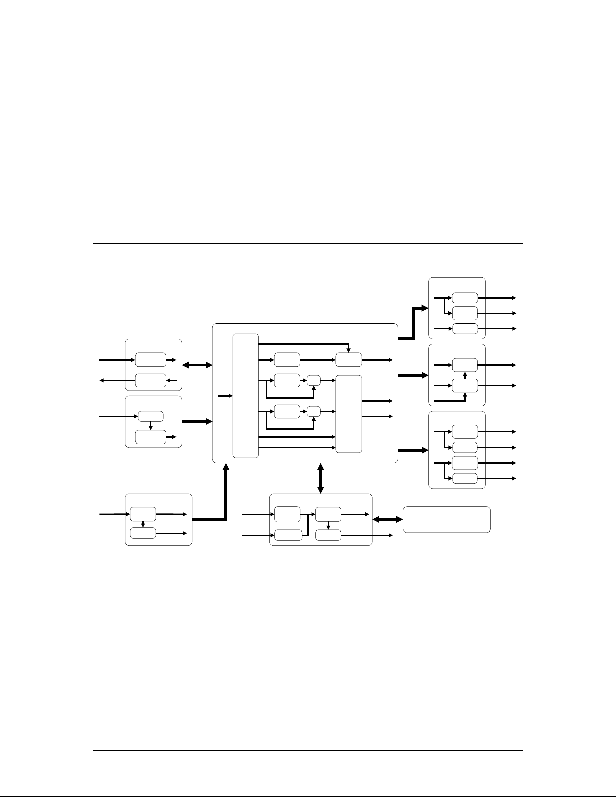
BitLink Professional HDTV Decoder block diagram
BitLink Professional HDTV Decoder
The BitLink Professional HDTV Decoder (hereinafter called the
BitLink Decoder) meets the highest standards in picture quality,
flexibility and reliability, for both HDTV and SDTV. The BitLink
platform affords cable, satellite and terrestrial operators, plus new
players, a cost effective and flexible way to transit to the DTV Market.
The BitLink Decoder supports extensive decoding and system modes
making it ideally suitable for use in ATSC/DVB contribution and
professional network monitoring applications.
User's Manual Overview • 1
Page 8

Video decoding formats cover interlaced and progressive HDTV
formats as well as SDTV for 60Hz. Both digital and analogue video
outputs are available.
The BitLink Decoder comprises of a 1RU rack-mounted, forced-air
cooled frame.
Modular Approach
The BitLink Decoder was designed with modularity as a key criteria.
This modularity facilitates easy adaptation to a number of different, and
in some cases not so obvious, decoding/DTV applications. The I/O
modules provide extensive choices in terms of transport stream
interfaces, e.g. 8/QPSK, ASI, analogue or digital video outputs, digital
and analogue audio outputs and video reference input. All transport
stream interfaces, except for the 8/QPSK demodulator, also provides
independent outputs that can be routed from any available input
module. In this way the "decoder" can be used for format conversions,
e.g. from QPSK to ASI.
General Features
MPEG-2 MP@HL and MP@ML
Transport stream input options include: ASI, QPSK
Support for up- and down-conversions
Up to two digital PCM and analogue audio pairs
Pass-through of Dolby Digital (AC-3)
Closed Caption support
Front panel, Web or Serial control
2 • Overview User's Manual
Page 9

2. Installation
Injury Precautions
WARNING!
If handled improperly, this equipment can be hazardous under certain
conditions. During servicing, this equipment must be handled with care to
avoid high voltage electric shock
Below are precautionary measures that must be considered before
operating the BitLink Decoder
Do not operate without lid
To avoid electrical shock or fire hazard, do not operate this
product without lid properly attached to the units. Only
qualified personnel should perform servicing.
Use proper power cord
To avoid fire hazard, use only the power cord supplied with
this products.
Do not operate in wet or damp conditions
To avoid electrical shock or fire hazard, do not operate this
products in wet or damp conditions.
Product Damage Precautions
WARNING!
Turn off AC power to the chassis before removing or installing printed circuit
assemblies, as this could result in serious damage to the unit’s components.
Below are precautionary measures that must be considered before
operating the BitLink Decoder
Use proper power source
Do not operate this product from a power source that supplies
more or less than the voltage specified for the products.
Provide proper ventilation
User’s Manual Installation • 3
Page 10

To prevent product overheating, provide proper ventilation and
do not obstruct the ventilation areas on the units.
Do not operate with suspected failures
If you suspect there is damage to the products, have it
inspected by qualified service personnel. Do not attempt to
repair the failure even if you suspect it may be a minor
problem.
Packaging
Visual check
When you receive the BitLink Decoder, examine the package for
obvious signs of damage. The delivery should not be accepted if the
packaging is damaged.
Open the packaging carefully and check for any obvious product
damage incurred during shipping. If there is any damage please contact
your distributor immediately.
Unpacking
Check the equipment against the delivery/packing note when
unpacked.
Retain the packaging, as it is required for warranty shipments.
Don’t grasp the unit’s front panel when unpacking.
General Installation Instructions
WARNING!
These installation instructions are for use by trained personnel only. To
reduce risk of electric shock, refer servicing to qualified personnel only.
Site Requirements
An ambient temperature should be maintained between 10 deg C (45
deg F) and 40 deg C (104 deg F) at a relative humidity of 10-90% (noncondensing)
WARNING!
To avoid electric shock, never remove the unit’s lid. There are no user
serviceable parts inside. Refer servicing to qualified personnel. Failure to
comply may result in equipment damage and/or personal injury.
WARNING!
Always remove main cord from unit before removing the front panel or the I/O
modules.
4 • Installation User's Manual
Page 11
Electrical power connection
WARNING!
The equipment must be grounded to avoid electrical shock. Failure to ground
the unit may cause equipment damage and/or personal injury. Particular
attention should be given to supply connections when connecting to power
strips rather then direct connections to branch circuits.
Physical Data
Height 1RU
Width 19” (483 mm)
Depth 18,1” (461 mm)
Weight (approx) 1) 9 kg
Power (Max) 1) 60 W
Voltage 90-120 V /60 Hz
Fuse 2,0 A (slow)
1) Depending on configuration
Also see Appendix B for full specification.
Mounting the BitLink Decoder
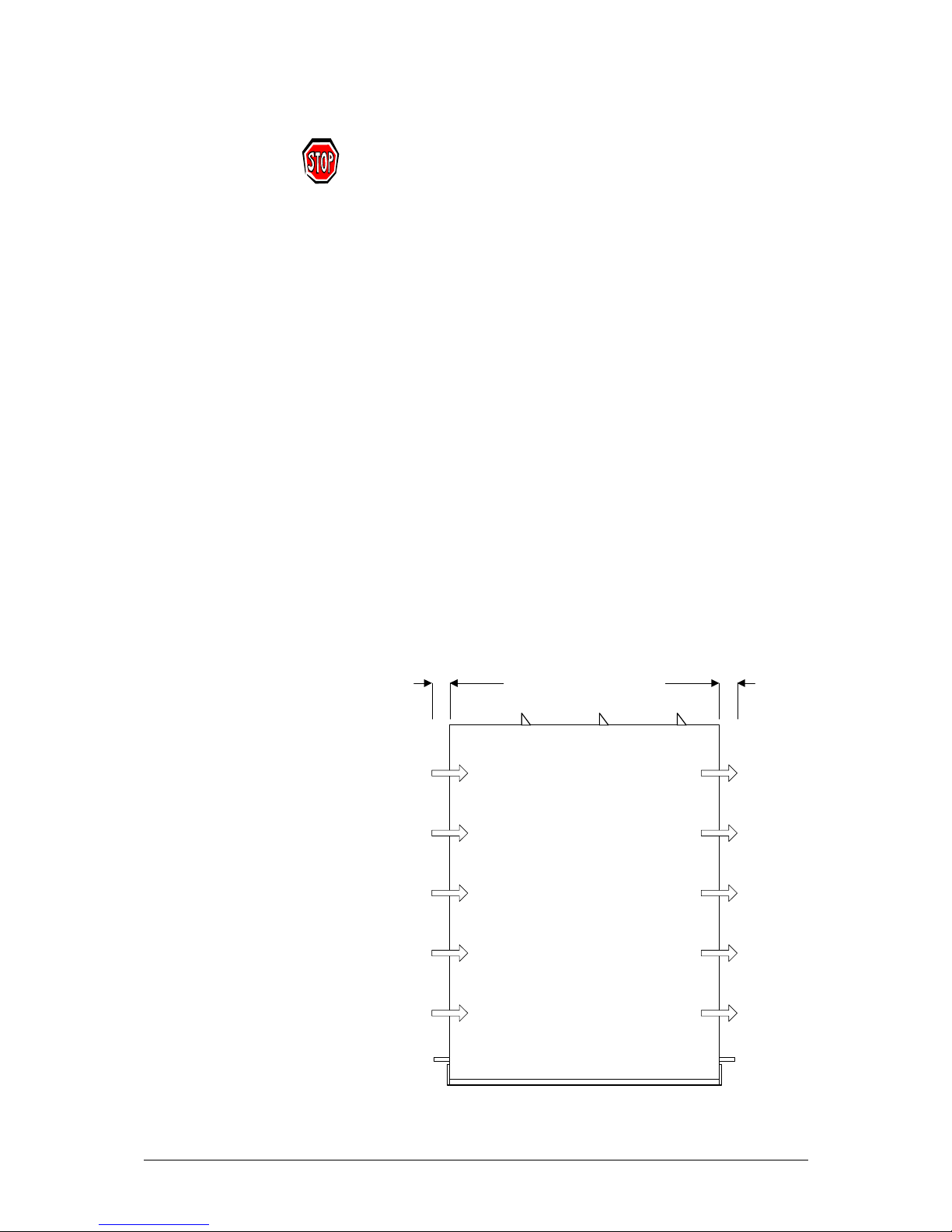
The BitLink Decoder has forced cooling with airflow from left to right.
When installing the BitLink Decoder, it must be placed so that there is a
gap of minimum 1 inch (25 mm) on the both sides of the unit to allow
for proper cooling.
1 inch 1 inch
Top view
Front
Air
flow
User’s Manual Installation • 5
Page 12
The BitLink Decoder can be mounted directly in a 19” rack, using the
supplied rack mounting hardware (for both front and rear side).
WARNING!
Do not put any extra weight on top of the BitLink Decoder when mounted in a
rack.
Connecting
Transport Stream Input
Ensure you have a valid transport stream on either the ASI or the RF
(demodulator) input.
Default (out of the box) setting is ASI 1.
Note! Coaxial cables for ASI inputs and outputs must be double-shielded.
Video Output
Use one of the video outputs and connect to your monitor.
Note! Coaxial cables for SDI outputs must be double-shielded.
Audio Output
Connect the audio output (if available) from the BitLink Decoder to an
audio amplifier or similar.
Default (out of the box) setting is decoded audio, available on both
analogue and digital outputs.
Power
After connecting TS, Video and Audio, power up the unit.
For detailed information on connectors, see Connections, page 33.
6 • Installation User's Manual
Page 13
3. Getting Started
General
This section will quickly guide you through the basics of operation and
how to connect and set up the BitLink Decoder from the front panel.
Front Panel operation
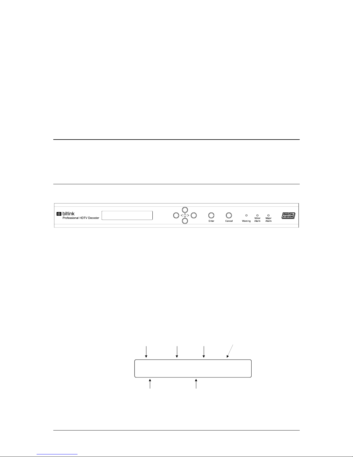
BitLink Decoder front panel
Display
The display on the front of the BitLink Decoder is a 2x24 character
backlit LCD display and is used to show status, menu selections and
settings.
Status Menu
When powering up the BitLink Decoder, the Status menu appears. The
Status menu has four different pages, which are navigated using the left
and the right arrow button.
Main status and video format
Prg_#3_ASI1_Trans_DD
Pid_49,_480i/29.97
Selected
program
Video PID
Decoded video
stream format
Selected
input source
Output
format
Audio 1 & 2 format
D = Dolby Digital (decode)
d = Dolby Digital (bypass)
M = MPEG (decode)
m = mpeg (bypass)
User’s Manual Getting Started • 7
Page 14
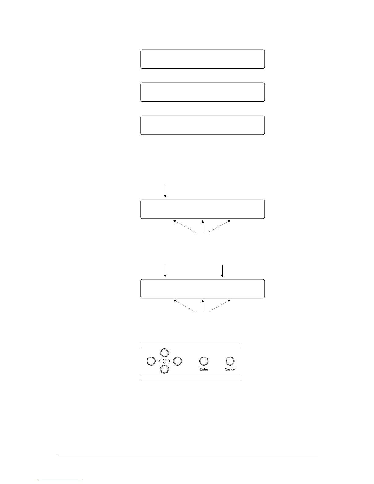
Audio channel 1 status
Audio_channel_1:
Pid_52,_AC3
Audio channel 2 status
Audio_channel_2:
Pid_53,_AC3
RF input level status
RF_-34.55_dBm
BER_0E-6_/_1.5E-15
To return to the Status menu after settings has been changed or menus
have been browsed press the cancel button until the Status menu is
shown again.
Selecting a Menu
MAIN_MENU
Status__>Wizard<___Input
Current Menu
Menus
Selecting a Setting
AUDIO_1_TYPE_(AC-3)
PCM_____>AC-3<___Dolby-E
Current Menu
Settings
Current Setting
Menu Navigation
Navigation Buttons
Press Enter to enter a new menu, selecting a setting to change
and confirm the change
Use the Arrow buttons to go up or down in the menu
structure, browse through a menu or to change settings
Press Cancel to return to a higher level in the menu structure
8 • Getting Started User's Manual
Page 15
Changing Values
Values (e.g. PIDs) may be modified by first selecting the digit using the
left or right arrow button and then increase with the up arrow button or
decrease with the down arrow button.
Confirm modified value with the Enter button or press the Cancel
button to cancel the change.
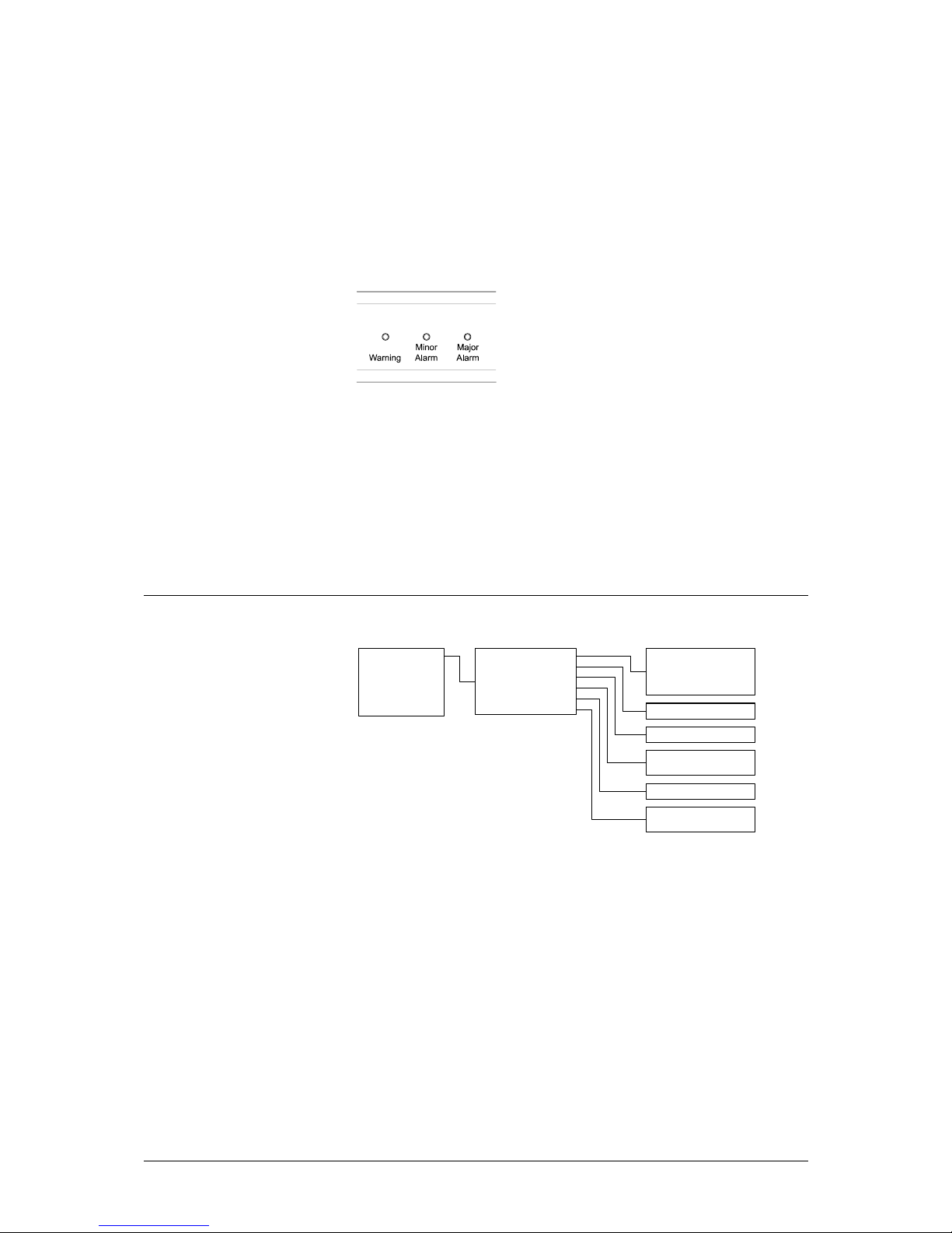
Alarms
Alarm Indicators
Alarms (or events) occurring are indicated on the front panel with
different severities; Warning, Minor Alarm and Major Alarm. The Web
interface provides information on the alarm source and an event history.
Alarms are also indicated via the Alarms connector on the rear.
To clear/reset alarms, select menu item Utilities > Clear Alarms.
The severity levels can be changed in the Web interface. Also see
Appendix B for default severity levels.
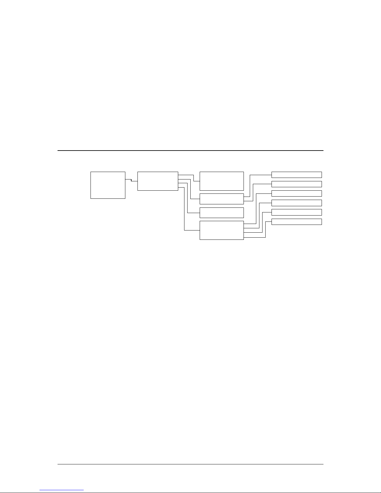
Wizard menu
Wizard
Input
Output
Utilities
Set-up
Info
Input Source
Program
Audio 1 Stream
Audio 1 Decode
Audio 2 Stream
Audio 2 Decode
ASI 1
ASI 2
RF 1
RF 2
<Select Program>
<Select Stream>
On
Bypass
<Select Stream>
On
Bypass
The Wizard is used to quickly set up the BitLink Decoder. More
advanced settings are available in the other menus.
Confirm and go to next menu item by pressing Enter.
Use Up and Down arrows to step between menu items.
Exit the Wizard by pressing Cancel.
Input Source
Select which input (ASI 1, ASI 2, RF 1 or RF 2) to be used.
Program
Select which Program in the transport stream to decode.
User’s Manual Getting Started • 9
Page 16

Audio 1 Stream
The channel selection provides a list of available audio streams found in
the transport stream. The selection is output to audio out 1.
Audio 1 Decode
The Decode control selects whether the audio is to be decoded (on) or
sent undecoded (bypass) to digital audio out 1.
Audio 2 Stream
The channel selection provides a list of available audio streams found in
the transport stream. The selection is output to audio out 2.
Audio 2 Decode
The Decode control selects whether the audio is to be decoded (on) or
sent undecoded (bypass) to digital audio out 2.
10 • Getting Started User's Manual
Page 17
4. Front Panel Control
Input menu
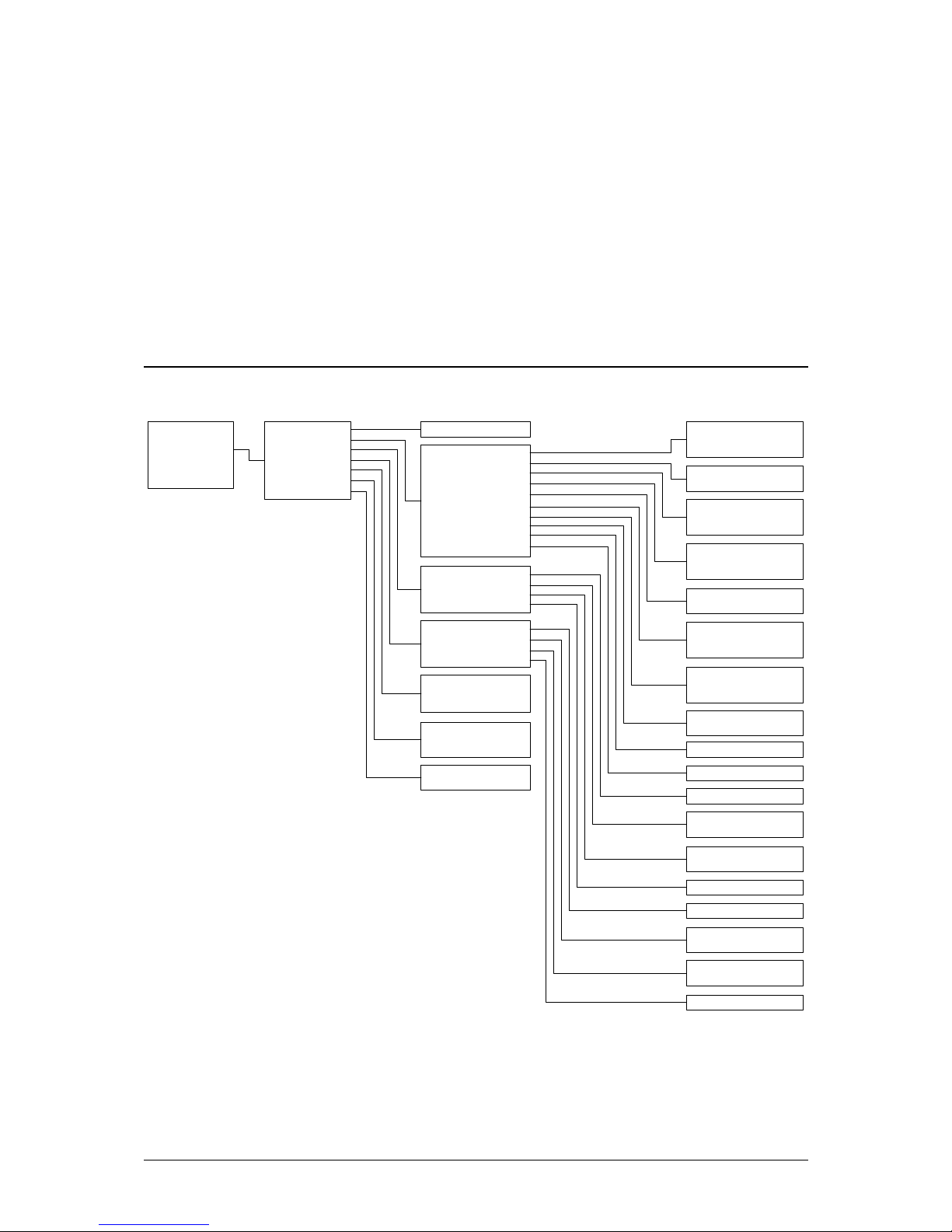
Wizard
Input
Output
Utilities
Set-up
Info
Input Source
RF Settings
Video Ref
Video Ref Pos
ASI 1
ASI 2
RF 1
RF 2
Frequency
Symbol Rate
Stream PCR
External
<Enter Frequency>
<Enter Symbol Rate>
SDTV Horizontal
SDTV Vertical
HDTV Horizontal
HDTV Vertical
<Enter Pos>
<Enter Pos>
<Enter Pos>
<Enter Pos>
Input Source
Input > Input Source
The Input Source selection determines which TS input that will be
decoded.
RF Settings
The controls found in the RF Settings menu are used for the optional
QPSK Demodulator.
Frequency
Input > RF Settings > Frequency
Sets L-band frequency, 950 000 – 2 150 000 kHz
Symbol Rate
Input > RF Settings > Symbol Rate
Sets Symbol rate, 1 000 000 – 45 000 000 baud.
Video Ref
Input > Video Ref
User’s Manual Front Panel Control • 11
Page 18
This control determines whether the video and audio outputs should be
locked to the PCR (from the stream) or to an external video reference
connected to the optional Video Reference module (GLK).
For detailed information on connectors, see Connections, page 33.
Video Ref Pos
Input > Video Ref Pos
Adjusts the video relative the video ref position up to ±1000
pixels/lines with 1 pixel/line resolution.
Audio is not affected.
Output menu
Wizard
Input
Output
Utilities
Set-up
Info
Program
Video
Audio 1
Audio 2
ASI 1
ASI 2
Auto Tune
Transparent
SDTV
HDTV
4:3
16:9
Auto
Full Frame
Bars
<Enter Video PID>
<Enter PCR PID>
<Select Stream>
On
Bypass
AC-3
MPEG-1
<Enter PID>
<Select Stream>
On
Bypass
AC-3
MPEG-1
<Enter PID>
Output Format
Monitor Aspect
Display Mode
Analogue SDTV
Analogue HDTV
Test Pattern
Audio Embed
CC Embed
Video PID
PCR PID
<Select Program>
Stream
Decode
Type
PID
Stream
Decode
Type
PID
ASI 1
ASI 2
RF
ASI 1
ASI 2
RF
Cancel
Auto Tune
RGB
YPbPr
CVBS
RGB
YPbPr
On
Off
Auto
Off
Force Bypass
Off
SDTV
HDTV
12 • Front Panel Control User's Manual
Page 19

Program
Output > Program
The BitLink Decoder scans the transport stream and extracts the
program information. Select the program to output from the list of the
identified programs in the stream.
Video
Output Format
Output > Video > Output Format
This control selects the video format to be displayed. Current selections
available are:
Transparent SD streams are displayed on the SD output. HD
streams are displayed on the HD output.
SDTV All streams are displayed on the SD output. HD
streams are downconverted to SD.
HDTV All streams are displayed on the HD output. SD
streams are upconverted to HD.
Monitor Aspect
Output > Video > Monitor Aspect
Determines the aspect ratio of the SDTV monitor (4:3 or 16:9). HDTV
monitors are always 16:9.
Display Mode
Output > Video > Display Mode
The Display Mode control determines how the stream is displayed:
Auto Does not change the picture.
Full Frame If the aspect ratio flag in the stream is set to 16:9, then
the output picture is cropped for 4:3 monitors.
Bars Compresses the picture either horizontally or vertically
adding black bars depending on Monitor Aspect setting.
Ignores the aspect ratio flag in the stream.
If Monitor Aspect has been set to 4:3, the
picture is compressed to letterbox format
(including horizontal bars).
If Monitor Aspect has been set to 16:9, the
picture is compressed horizontally and
vertical bars are displayed.
Analogue SDTV
Output > Video > Analogue SDTV
Select whether the analogue SDTV output format should be RGB,
YPbPr or CVBS.
User’s Manual Front Panel Control • 13
Page 20

Analogue HDTV
Output > Video > Analogue HDTV
Select whether the analogue HDTV output format should be RGB or
YPbPr.
Note! If YPbPr is selected, the VGA output does not have a valid signal.
Test Pattern
Output > Video > Test Pattern
The BitLink Decoder can output a colour bar test pattern to verify that
video is available. Select SDTV for a test pattern on the SD output or
HDTV for a test pattern on the HD output. Normally off.
Audio Embed
Output > Video > Audio Embed
Enable to embed audio on the optional SDI outputs.
Auto Embeds the audio, encoded or decoded, according to
the Audio Decode setting.
Off No audio embedding.
Force Bypass Embeds the audio from the stream independent of
Audio Decode setting.
CC Embed
Output > Video > CC Embed
Enable to embed Closed Caption on the video outputs.
Video PID
Output > Video > Video PID
Manual selection of Video PID if not available in the current program.
Normally the Program selection will automatically also set the PID.
PCR PID
Output > Video > PCR PID
Manual selection of PCR PID if not available in the current program.
Normally the Program selection will automatically also set the PID.
Audio 1
The settings found under menu Output > Audio 1 are used for audio
output 1. Settings for audio out 2 are identical and found under menu
Output > Audio 2.
Stream
Output > Audio 1 > Stream
The channel selection provides a list of available audio streams found in
the transport stream. The selection is output to audio out 1.
14 • Front Panel Control User's Manual
Page 21

Decode
Output > Audio 1 > Decode
The Decode control selects whether the audio is to be decoded or sent
undecoded (bypassed) to digital audio output 1. Analogue audio is
always provided.
Type
Output > Audio 1 > Type
Overrides the audio channel selection by selecting the audio type (AC-3
or MPEG-1) manually.
PID
Output > Audio 1 > PID
Manual selection of Audio PID if not available in the current program.
Normally the Program selection in combination with Audio Stream
selection will automatically also set the PID.
Audio 2
The settings found under menu Output > Audio 2 are used for audio
out 2. For description of settings see Audio 1 earlier on.
ASI 1
Output > ASI 1
Determines the TS source to be routed to the ASI 1 output. Either ASI
1, ASI 2 or Demodulator (RF) output.
ASI 2
Output > ASI 2
Determines the TS source to be routed to the ASI 1 output. Either ASI
1, ASI 2 or Demodulator (RF) output.
Auto Tune
Output > Auto Tune
When Auto Tune is selected, the first program in the stream is
automatically chosen.
User’s Manual Front Panel Control • 15
Page 22
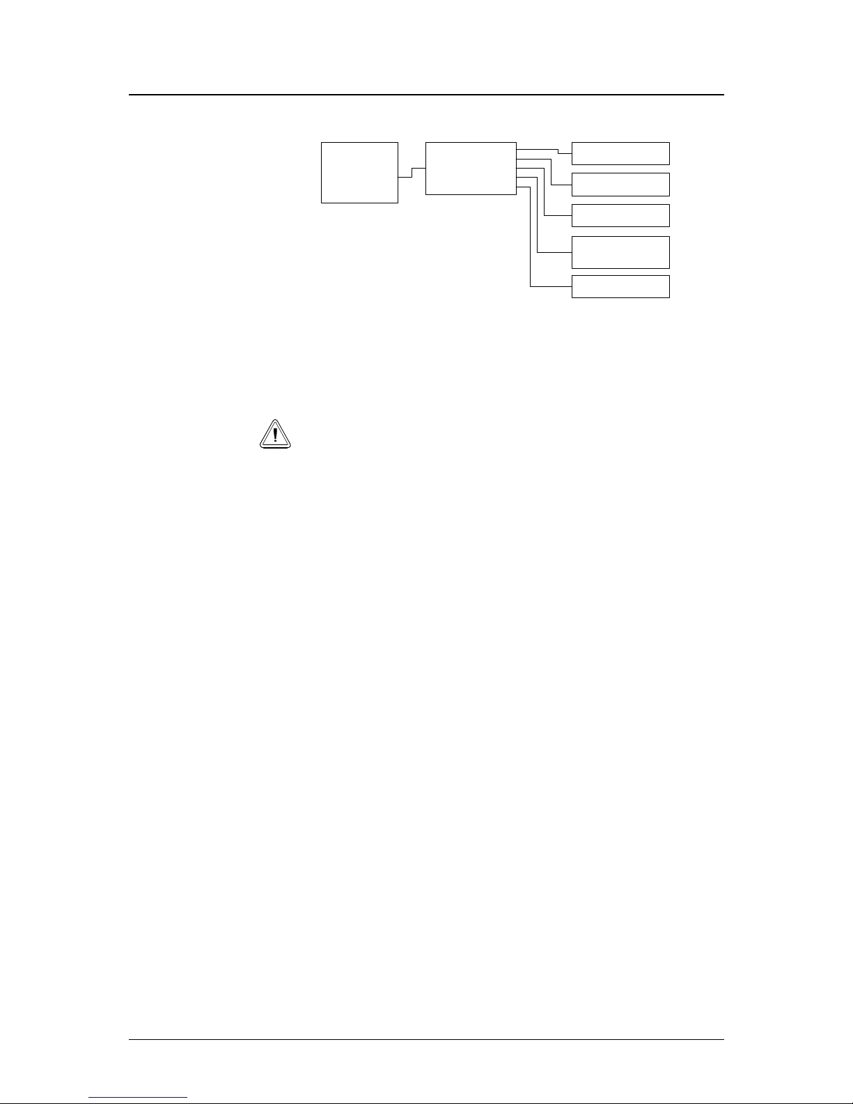
Utilities menu
Wizard
Input
Output
Utilities
Set-up
Info
Boot Other
Load Defaults
SW Upgrade
Remote Mode
Clear Alarms
Cancel
Boot
Cancel
Restore
Cancel
Upgrade
Local
Web
Serial
Cancel
Clear
Boot Other
Utilities > Boot Other
Programs another BitLink Decoder via the Ethernet connection on the
QMC module.
Note! Only for factory configuration.
Load Defaults
Utilities > Load Defaults
By using this control, the settings in the BitLink Decoder are restored to
factory defaults.
Factory Defaults
Input Source ASI 1
Program No. None
Video PID None
PCR PID None
Video Output Format Transparent
Monitor Aspect 4:3
Display Mode Full
CC Embed Enable
Audio Embed Enable
Test Pattern Off
Video Ref Stream PCR
ASI 1 Out ASI 1
ASI 2 Out ASI 2
RF Mode QPSK
2)
RF FEC 3/4
2)
RF Freq 1 362 000 kHz
RF Symbol Rate 14 028 731 baud
Audio 1 & 2 Stream None
16 • Front Panel Control User's Manual
Page 23

Audio 1 & 2 Decode On
Audio 1 & 2 Type Unknown
Analogue SDTV CVBS
Analogue HDTV RGB
Video ref Pos SDTV hor. 0
Video ref Pos SDTV ver. 0
Video ref Pos HDTV hor. 0
Video ref Pos HDTV ver. 0
1) Settings not listed above are not affected.
2) Not available from the front panel
SW Upgrade
Utilities > SW Upgrade
Allows software upgrade of the BitLink Decoder via the Ethernet
connection on the QMC module.
See separate instructions included with the new software.
Software upgrade is also possible via the Web interface.
Remote Mode
Utilities > Remote Mode
Determines how to control the BitLink Decoder; Local (front panel),
Web (web interface via Ethernet connector on the QMC module) or
Serial (RS232 on the QMC module).
Note! Only one Remote mode at the time is available. I.e. if Web is
selected, control is not possible from the front panel. Remote mode will
return to Local (front panel) as soon as one of the keys on the front panel is
touched.
Remote_mode_activated
Web_mode
To obtain protocol information for serial control of the BitLink
Decoder, see Serial Control, page 31.
Clear Alarms
Utilities > Clear Alarms
Clears/resets all current alarms indicated on the front panel and via the
alarms connector on the rear.
Note! Executing Clear Alarms will also clear the Event History in the Web
interface.
User’s Manual Front Panel Control • 17
Page 24

Set-up menu
Wizard
Input
Output
Utilities
Set-up
Info
IP Addr
Netmask
Gateway
Network
Network Restore
<Enter IP Address>
<Enter Netmask>
<Enter Gateway>
<Enter Network>
Cancel
Restore
The set-up menu is used to configure the BitLink Decoder for control
via Ethernet and the built-in web control interface.
IP Addr
Set-up > IP Addr
Sets the IP address of the BitLink Decoder.
Default IP address is 192.168.80.200.
Netmask
Set-up > Netmask
Sets the Netmask of the BitLink Decoder.
Default Netmask is 255.255.255.0.
Gateway
Set-up > Gateway
Sets the Gateway of the BitLink Decoder.
Default Gateway address is 192.168.80.1.
Network
Set-up > Network
Sets the Network of the BitLink Decoder.
Default Network address is 192.168.80.0.
Network Restore
Set-up > Network Restore
Select Restore to set all addresses to factory default.
18 • Front Panel Control User's Manual
Page 25

Info
Wizard
Input
Output
Utilities
Set-up
Info
Decoder <ver>
QMC <ver>
QMC FPGA <ver>
DPB <ver>
GLK <ver>
Software
Hardware
Temperature
Slot 6 QMC<ver><fco>
Slot 8 DPB<ver><fco><cfg>
Slot 1<hw><ver><fco>
Slot 2<hw><ver><fco>
Slot 3<hw><ver><fco>
Slot 4<hw><ver><fco>
Slot 5<hw><ver><fco>
QMC <temp F> <temp C>
QCP <temp F> <temp C>
Software
Info > Software
Displays the software version on the decoder and all the different
modules.
Hardware
Info > Hardware
Displays the hardware version, FCO level and for DPB, the I/O
configuration, on the different modules and in which slots they are
mounted.
Empty slots or modules not detected will be indicated as e.g. “Slot 1 No
board”.
Non-working modules will be indicated as e.g. “Slot 1 ASI Error”
Temperature
Info > Temperature
Displays the temperature on the QMC and the QCP (the power supply)
in both Fahrenheit and Celsius.
User’s Manual Front Panel Control • 19
Page 26

20 • Front Panel Control User's Manual
Page 27
5. Web Control
General
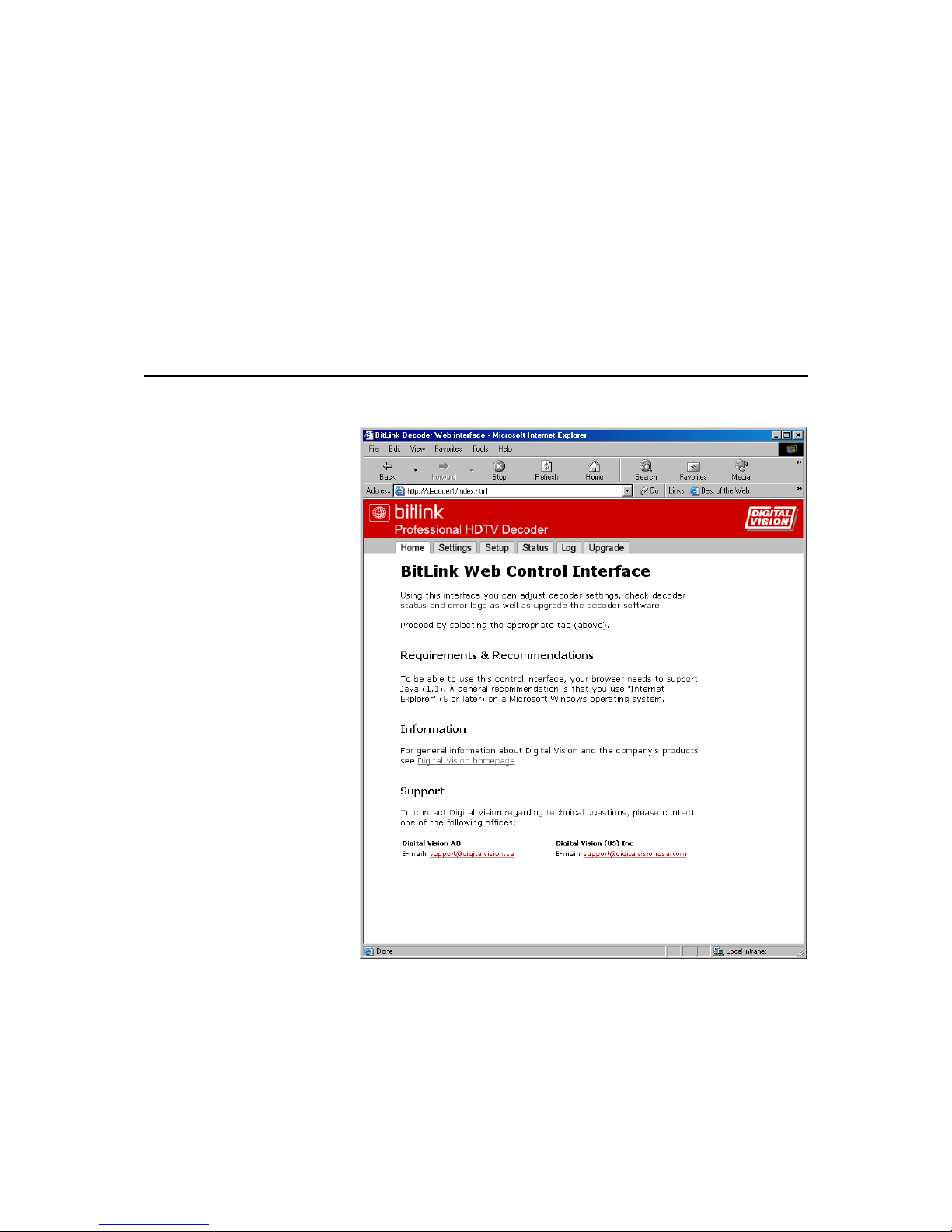
The built-in webserver provides a simple way of controlling and
monitoring the BitLink Decoder remotely. The web control interface
also gives a good overview of settings including alarms log.
User’s Manual Web Control • 21
Page 28
Configuration
1. While in Local control mode, select set-up menu from the front
panel and set IP address, Netmask, Gateway and Network.
2. Connect the BitLink Decoder to your network using a standard
RJ-45 Ethernet cable.
3. From the front panel, select menu Utilities > Remote > Web.
Note! It is only possible to use a remote control at the time. Therefore,
while the web interface is used, the front panel (local) control is locked. To
return to front panel control, select menu Utilities > Remote > Local.
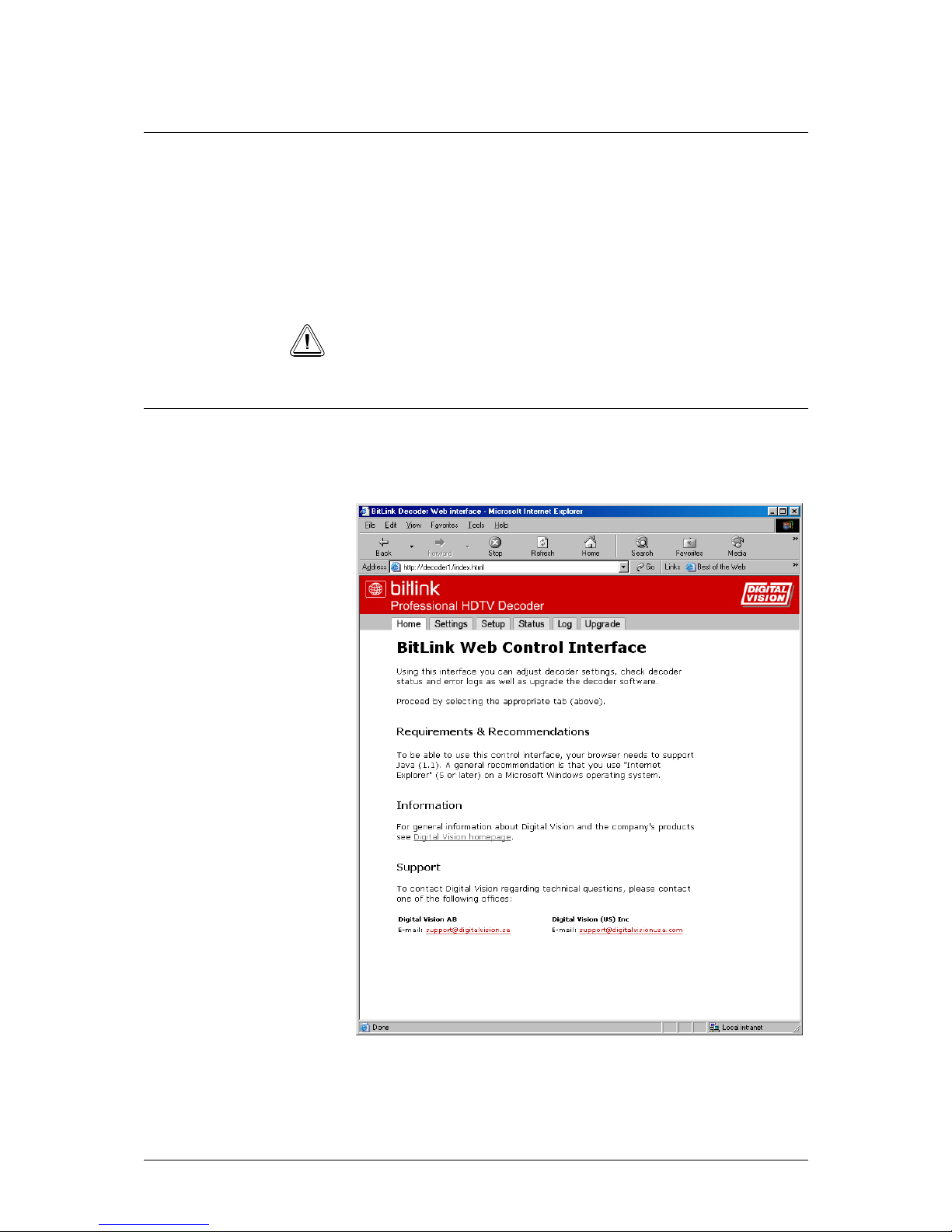
Starting
Start Internet Explorer. Type in the IP address (previously set-up from
the front panel) in the address field.
22 • Web Control User's Manual
Page 29
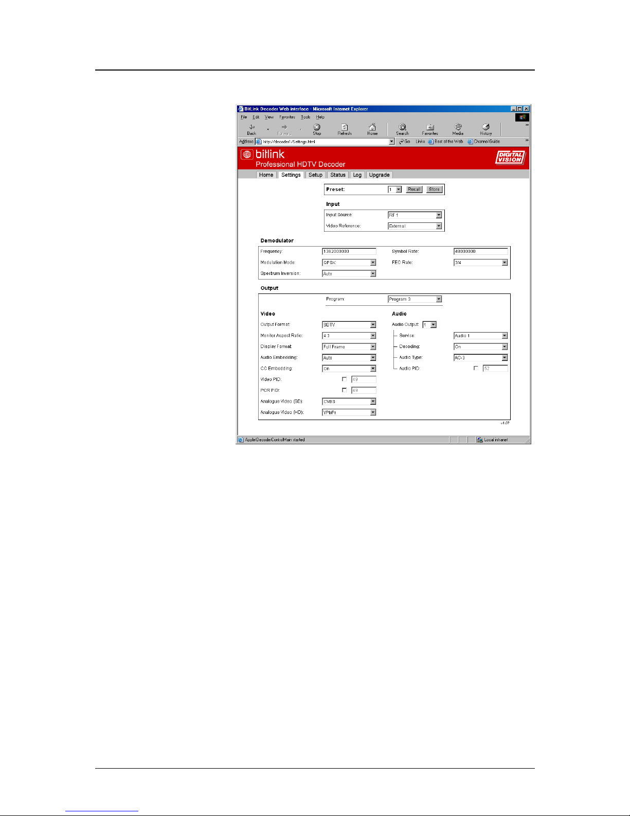
Settings
Preset
Future implementation.
Input
Input Source
The Input Source selection determines which TS input that will be
decoded.
Video Ref
This control determines whether the video and audio outputs should be
locked to the PCR (from the stream) or to an external video reference
connected to the optional Video Reference module (GLK).
For detailed information on connectors, see Connections, page 33.
Demodulator
The controls found in the Demodulator section are used for the
optional QPSK Demodulator.
User’s Manual Web Control • 23
Page 30

Frequency
Sets L-band frequency, 950 000 – 2 150 000 kHz
Modulation Mode
Future implementation.
Spectrum Inversion
Future implementation.
Symbol Rate
Sets Symbol rate, 1 000 000 – 45 000 000 baud.
FEC Rate
Forward Error Correction: Auto, 1/2, 2/3, 3/4, 5/6, 6/7, 7/8 or 8/9.
Output
Program
The BitLink Decoder scans the transport stream and extracts the
program information. Select the program to output from the list of the
identified programs in the stream.
Video
Output Format
This control selects the video format to be displayed. Current selections
available are:
Transparent SD streams are displayed on the SD output. HD
streams are displayed on the HD output.
SDTV All streams are displayed on the SD output. HD
streams are downconverted to SD.
HDTV All streams are displayed on the HD output. SD
streams are upconverted to HD.
Monitor Aspect Ratio
Determines the aspect ratio of the SDTV monitor (4:3 or 16:9). HDTV
monitors are always 16:9.
Display Format
The Display Format control determines how the stream is displayed:
Auto Does not change the picture.
Full Frame If the aspect ratio flag in the stream is set to 16:9, then
the output picture is cropped for 4:3 monitors.
Bars Compresses the picture either horizontally or vertically
adding black bars depending on Monitor Aspect Ratio
setting. Ignores the aspect ratio flag in the stream.
If Monitor Aspect Ratio has been set to 4:3,
the picture is compressed to letterbox
format (including horizontal bars).
24 • Web Control User's Manual
Page 31

If Monitor Aspect Ratio has been set to
16:9, the picture is compressed horizontally
and vertical bars are displayed.
Audio Embedding
Enable to embed audio on the optional SDI outputs.
CC Embedding
Enable to embed Closed Caption on the video outputs.
Video PID
The Program selection will automatically set the Video PID.
By selecting the checkbox, a PID can be entered manually.
PCR PID
The Program selection will automatically set the PCR PID.
By selecting the checkbox, a PID can be entered manually.
Analogue Video (SD)
Select whether the analogue SDTV output format should be RGB,
YPbPr or CVBS.
Analogue Video (HD)
Select whether the analogue HDTV output format should be RGB or
YPbPr.
Note! If YPbPr is selected, the VGA output does not have a valid signal.
Audio
Audio Output
The settings below are valid for the selected Audio Output.
Service
The service selection provides a list of available audio streams found in
the transport stream. The selection is output to the selected audio
output.
Decoding
The Decoding control selects whether the audio is to be decoded or
sent undecoded (bypassed) to digital audio output 1. Analogue audio is
always provided.
Audio Type
Overrides the audio channel selection by selecting the audio type (AC-3
or MPEG-1) manually.
Audio PID
The Program selection in combination with selected Audio Service will
automatically set the Audio PID.
By selecting the checkbox, a PID can be entered manually.
User’s Manual Web Control • 25
Page 32
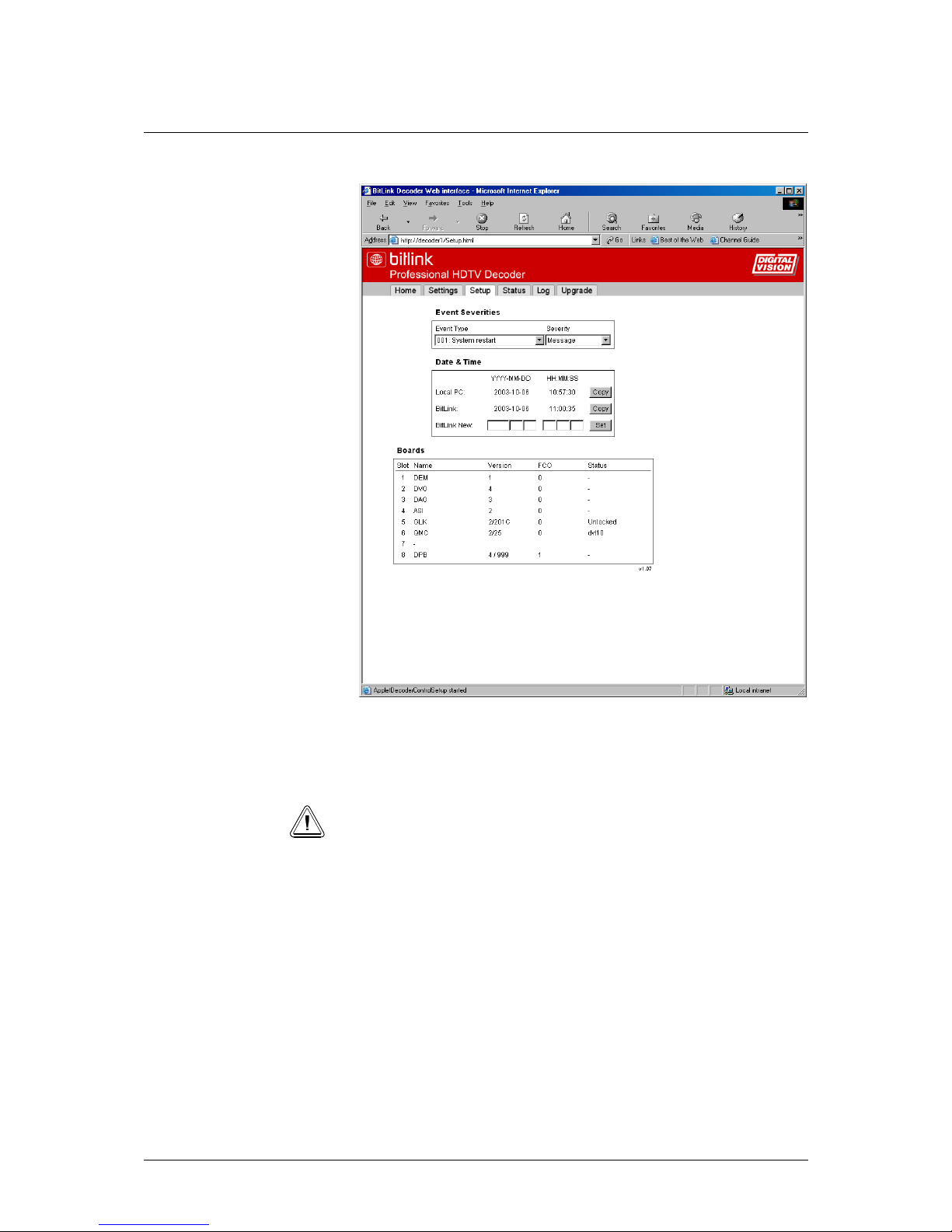
Setup
Event Severities
Sets the severity of different events to be indicated in the Event History,
the Front Panel and the Alarms connector.
Note! The severity Message will not be indicated on the front panel or
Alarms connector.
See Appendix B for default severity levels.
Date & Time
Sets date and time for the BitLink Decoder. Important for the Event
History.
Boards
Displays the hardware version, FCO level on the different modules and
in which slots they are mounted.
26 • Web Control User's Manual
Page 33
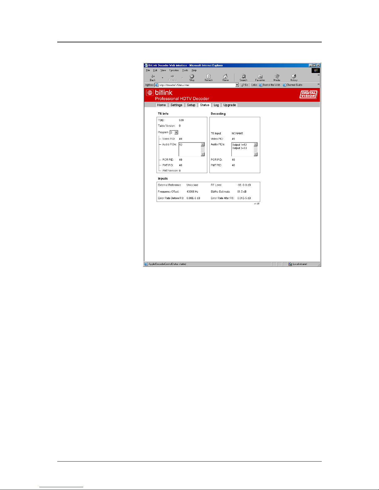
Status
TS Info
Provides information on input TS stream such as program number and
PIDs.
Decoding
Provides information on current decoding program such as name and
PIDs.
Inputs
Information on whether the BitLink Decoder is locked or unlocked to
the external video reference.
RF Status
RF Level is the RF input level in dBm.
Frequency Offset is the carrier frequency offset in Hz.
Eb/No Estimate in dB.
Error Rate Before RS (Reed Solomon) byte rate/s.
Error Rate After RS in bits/s.
User’s Manual Web Control • 27
Page 34
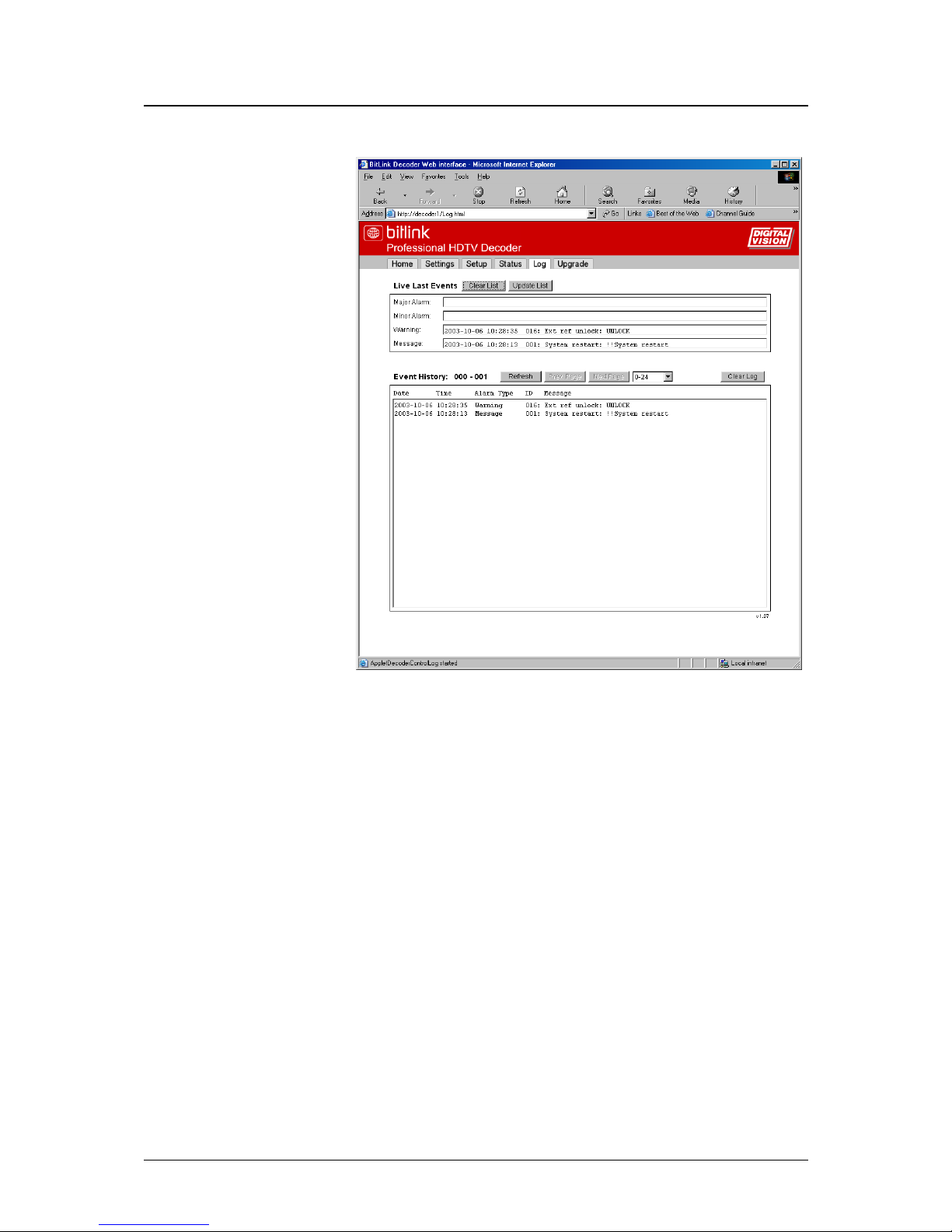
Log
Live Last Events
Provides information on the latest event for each severity type.
Event History
The Event History provides a list/log on all events since the Clear Log
button was pushed.
28 • Web Control User's Manual
Page 35
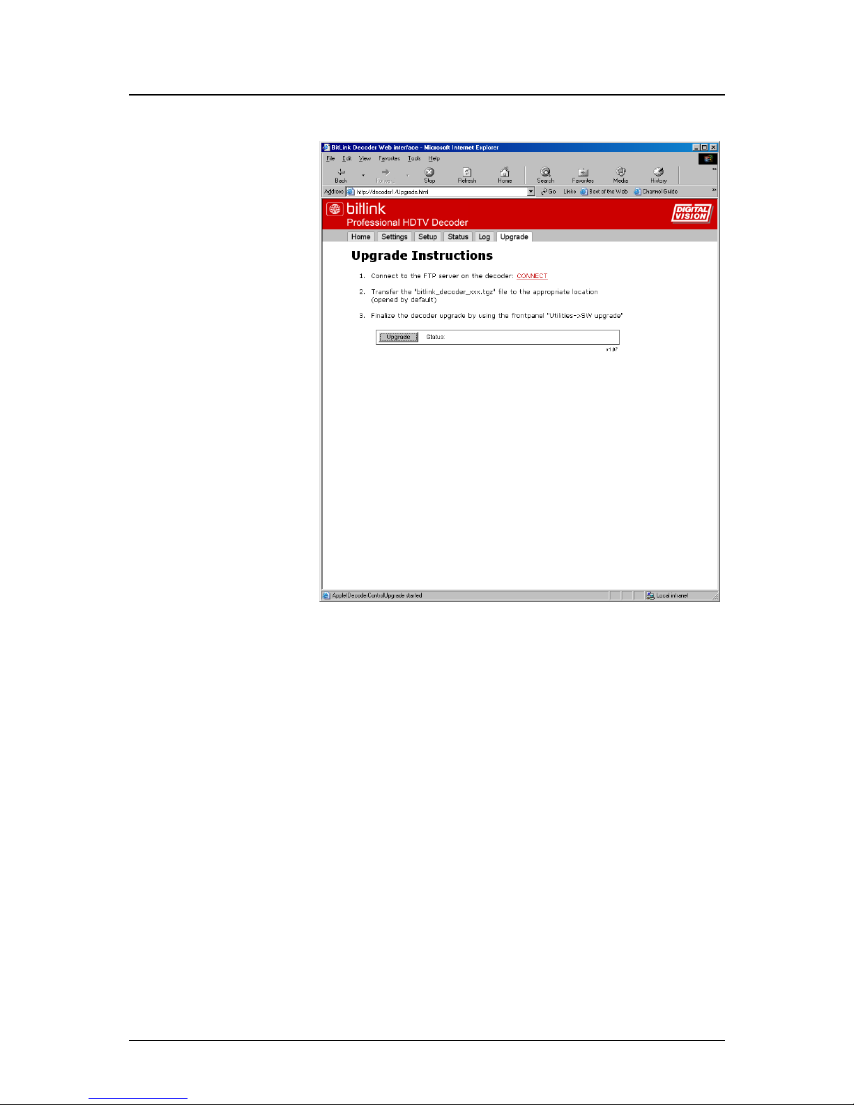
Upgrade
The Upgrade page allows easy software updates. Just follow the
instructions.
User’s Manual Web Control • 29
Page 36

30 • Web Control User's Manual
Page 37

6. Serial Control
General
Serial control from 3rd party controllers is possible via the RS232
interface.
To obtain a copy of the BitLink Decoder serial control protocol, a
NDA has to be signed.
Contact one of Digital Vision’s offices:
Head Office
Digital Vision AB
Solna Strandväg 98
SE-171 54 Solna
Sweden
Tel: +46 (0)8 546 182 00
Fax: +46 (0)8 546 182 09
E-mail: [email protected]
[email protected]
Sales Office, US
Digital Vision (US) Inc.
4605 Lankershim Blvd, Suite 700
North Hollywood, CA 91602
USA
Tel: +1 818 769-8111
Fax: +1 818 769-1888
E-mail: [email protected]
[email protected]
User’s Manual Serial Control • 31
Page 38

32 • Serial Control User's Manual
Page 39
7. Connections
General
The BitLink Decoder has a wide range of input and output interface
modules available and can be configured in a number of different ways.
The following sections will describe the different modules and their
connectors.
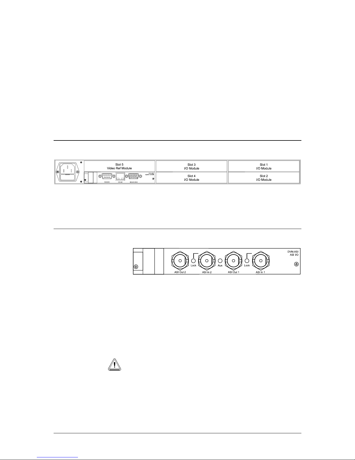
ASI module
The ASI module provides dual ASI transport stream input and outputs.
Note! This module is optional.
ASI Out 1/2
DVB-ASI output, BNC 75 ohm (looped from input or any other TS
input module).
ASI In 1/2
DVB-ASI input, BNC 75 ohm.
Lock LEDs indicates when a valid transport stream is provided.
Note! Coaxial cables must be double-shielded.
User’s Manual Connections • 33
Page 40
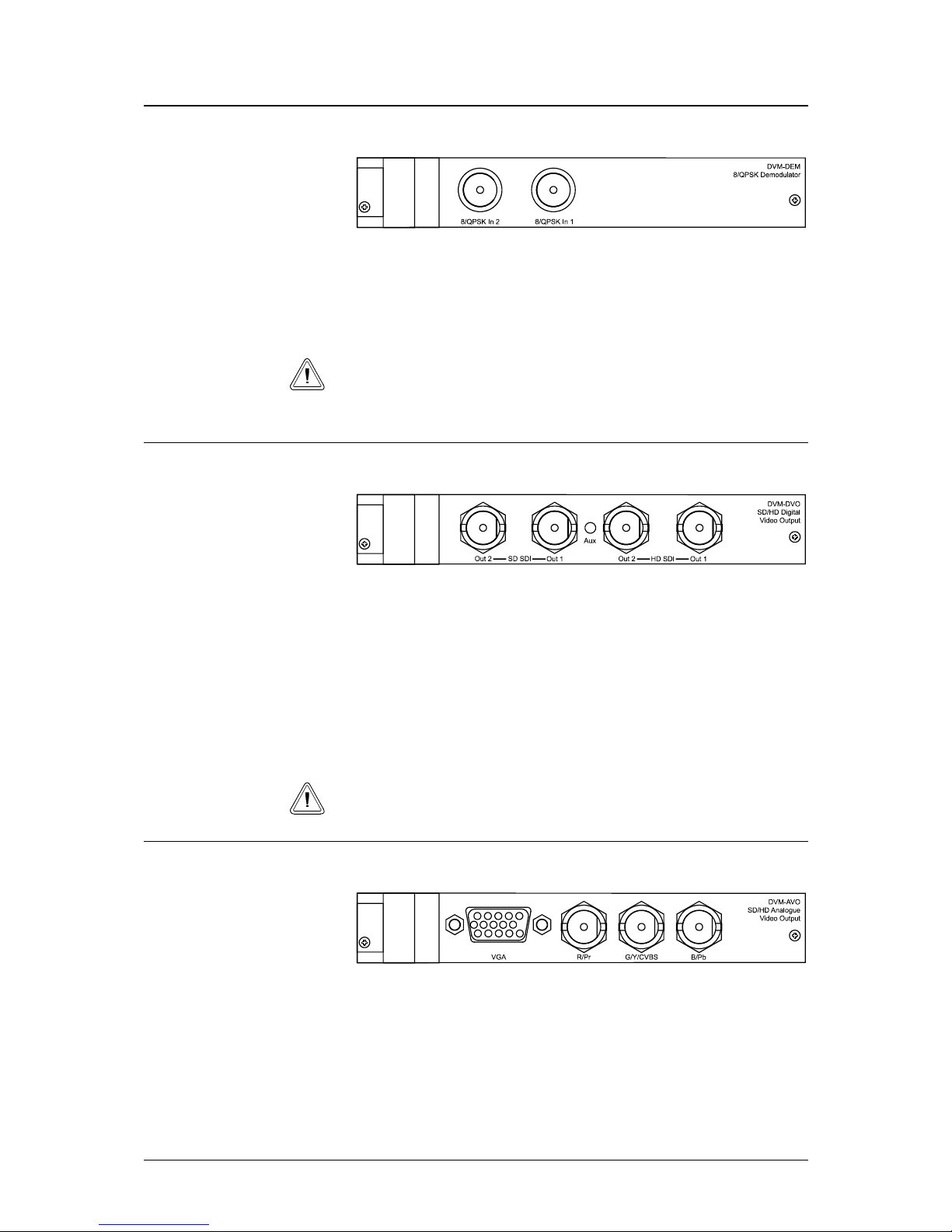
8/QPSK Demodulator module (DEM)
The DEM module is an L-Band RF 8/QPSK, 16QAM demodulator
(950 – 2150 MHz) with two inputs.
Note! This module is optional.
8/QPSK In 1/2
2x F-type 75 ohm. These inputs can be routed to ASI outputs.
Note! If both inputs are connected to signals with the same frequency and
bitrate, the signal strength need to be reduced to -55 dBm, due to cross talk
of -25 dBm between inputs.
Digital Video Output module (DVO)
The Digital Video Output module (DVO) provides digital outputs
separately for both SDTV and HDTV. Note that only SDTV or HDTV
outputs are active at a time.
Note! This module is optional.
SD SDI Out 1/2
2x Serial digital SDTV output according to ITU-R BT.656.
HD SDI Out 1/2
2x Serial digital HDTV output according to SMPTE292M.
Note! Coaxial cables must be double-shielded.
Analogue Video Output module (AVO)
The Analogue Video Output module (AVO) provides analogue outputs
for both SDTV and HDTV. Note that only SDTV or HDTV outputs
are active at a time.
Note! This module is optional.
VGA
VGA HD output (RGBHV).
34 • Connections User's Manual
Page 41
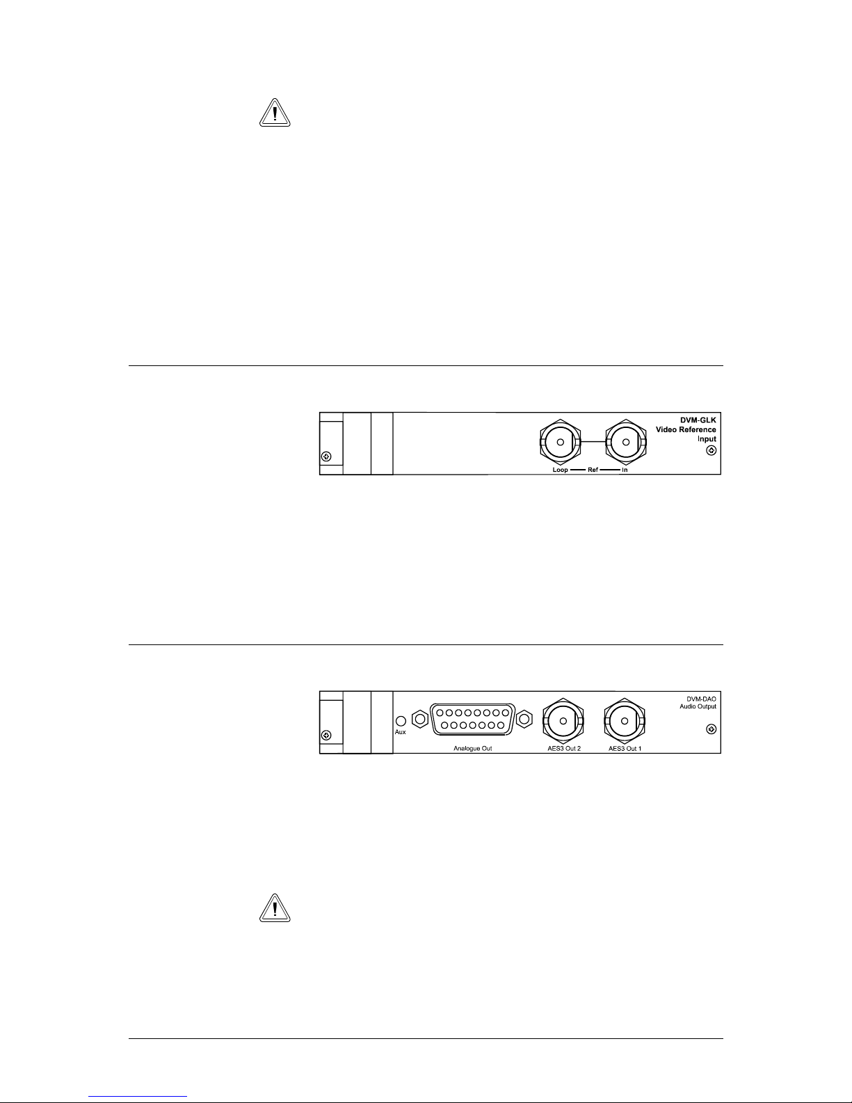
Note! Only active for HDTV and if YPbPr is selected, the VGA output
does not have a valid signal.
R/Pr
Pr Colour difference signal or Red depending on the mode chosen in
the menu Output > Video > Analogue Format SDTV and HDTV
respectively.
G/Y/CVBS
Luminance or Green analogue output or Composite PAL/NTSC
output depending on the mode chosen.
B/Pb
Pb Colour difference signal or Blue depending on the mode chosen.
Video Reference Input module (GLK)
The Video Reference Input module can be used to lock the output
video to an external composite video reference as an alternative to the
PCR in the transport stream.
Note! This module is optional.
Video Ref
Composite video reference input with loop through according to ITU-R
Rec. BT.470-3. Needs to be terminated with 75 ohm.
Audio Output module (DAO)
The Audio Output module (DAO) provides 2 channels of both
analogue and digital audio.
Note! This module is optional.
Analogue Out
2 balanced stereo pairs (same as digital outputs) on 1x DB15.
See Appendix A for pin-out.
Note! Analogue audio is only available if the audio is decoded.
AES3 Out 1
48kHz unbalanced digital audio output (SMPTE276).
User’s Manual Connections • 35
Page 42
AES3 Out 2
48kHz unbalanced digital audio output (SMPTE276).
System Controller module (QMC)
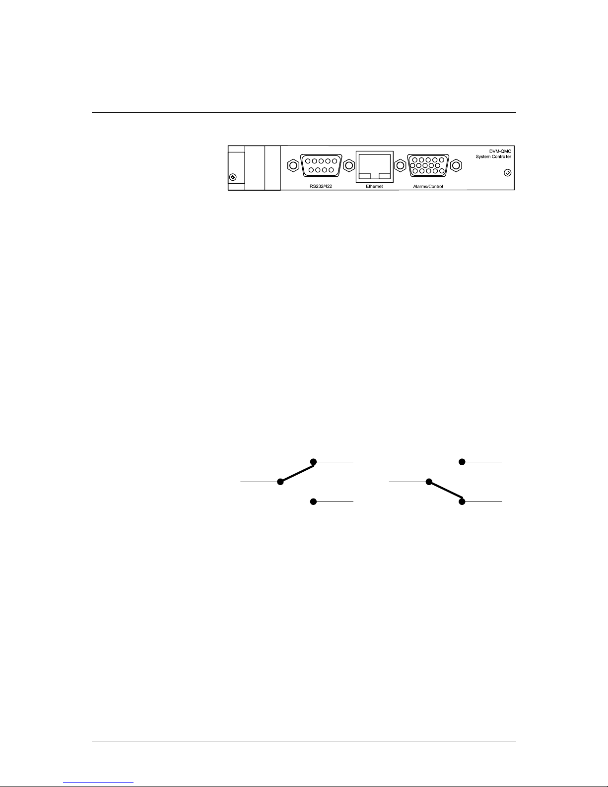
The System Controller module (QMC) provides an external
remote/control interface.
RS232/422
The RS232 port is used for 3
rd
party control of the BitLink Decoder.
To obtain protocol information, see Serial Control, page 31.
See Appendix A for pin-out.
Ethernet
The Ethernet connection is used for the Web interface (see page 21)
and to upgrade with new software.
Alarms/Control
The Alarms/Control connector is reserved for Alarm relays output and
future implementation of GPI.
The QMC has three alarm relays, one for warning alarms, one for minor
alarms and one for major alarms. Each relay is connected to three pins
on the Alarms/Control port. The three pins are called “common”, “A”
and “B”. When an alarm occurs there will be a short-circuit between
“common” and “A”. When no alarm is active there will be a shortcircuit between “common” and “B”.
common
A
B
common
A
B
Alarm active No alarm
The Alarms/Control port has two general purpose TTL inputs and two
general purpose TTL outputs.
See Appendix A for pin-out.
36 • Connections User's Manual
Page 43

Appendix A:
Rear Panel Connectors
Analogue Audio Out
Connector: Female DB15
1 gnd
2 Channel 1 L +
3 gnd
4 Channel 1 R +
5 gnd
6 Channel 2 L +
7 gnd
8 Channel 2 R +
9 Channel 1 L 10 gnd
11 Channel 1 R 12 gnd
13 Channel 2 L 14 gnd
15 Channel 2 R -
RS232/RS422
Connector: Female DB9
RS232
1 nc
2 Tx
3 Rx
4 nc
5 gnd
6 nc
7 nc
8 nc
9 gnd
RS422
1 nc
2 Tx3 Rx+
4 nc
User’s Manual Appendix A • 37
Page 44

5 gnd
6 nc
7 Tx+
8 Rx9 nc
Alarms/Control
Connector: Female HDDB15
1 gnd
2 Major alarm A
3 Major alarm B
4 GP1 input
5 GP2 input
6 Minor alarm common
7 Major alarm common
8 Warning alarm common
9 GP1 output
10 GP2 output
11 Minor alarm A
12 Minor alarm B
13 Warning alarm A
14 Warning alarm B
15 Vcc +5V
1)
1) The Vcc +5V comes from a DC/DC converter and will vary
slightly around +5V. Any kind of control logic can be connected to
the Alarms/Control connector, but if the Vcc +5V is used, the load
current must not exceed 100 mA.
38 • Appendix A User's Manual
Page 45

Appendix B:
Events and Severities
Event
ID
Default
Severity Description
1 Message System restart. QMC sets this event at start-up
8 Minor Decoder board 1 (DPB) faulty
10 Minor Control board (QMC) faulty
11 Minor Option board slot 1 faulty
12 Minor Option board slot 2 faulty
13 Minor Option board slot 3 faulty
14 Minor Option board slot 4 faulty
15 Minor Option board slot 5 faulty
16 Warning Cannot lock to reference genlock video
17 Major High temperature (65° C / 149° F)
25 Warning System reset due to an internal error
User’s Manual Appendix B • 39
Page 46

40 • Appendix B User's Manual
Page 47

Appendix C:
BitLink Decoder Specifications
Video Decoding
Standard MPEG-2 ISO/IEC 13818-2 up to 4:2:0 Main Profile
@ High Level
No. of programs
decoded
Single HDTV or SDTV.
HDTV programs may be down converted to SDTV
format. SDTV programs may be upconverted to
HDTV 1080i format
Bitrate Up to 60 Mb/s
Formats Supported
System Scanformat Horizontal
1080i/59.94 Interlace 1920/1440/1280/960
1080i/60 Interlace 1920/1440/1280/960
480i/59.94 Interlace 720/704/640/544/480/352
Audio Decoding
Decoding Two streams of Dolby Digital 5.1 (downmix)/stereo
or MPEG stereo
Pass-through Up to two streams of Dolby Digital (AC-3)
Closed Caption
Extraction of user
data
According or ATSC/53B
Re-insertion On line 21 according to EIA-608 on all SD outputs.
Control
Local Front panel control 2 x 24 character display
Web Ethernet
Serial RS232
User’s Manual Appendix C • 41
Page 48

Power
Voltage 90 to 120 VAC, 48 to 66 Hz
Consumption < 60 VA
Power-up time Typically 30 seconds until the unit can be operated, 50
seconds for video and audio output.
Mechanical
Height 1RU – 44.5 mm (1.8”)
Depth 461 mm (18.1”)
Width 483 mm (19”)
Weight 9 kg (19.8 lbs) typical
Cooling Forced air, side-to-side
Environmental
Operating
temperature
0ºC to +40ºC (32ºF to 104ºF)
Relative humidity Max 90% non-condensing
Safety
Approvals ETL
ASI module (optional)
No. of inputs 2, BNC 75 ohm
Type DVB-ASI
Outer loop demod 188
No. of outputs 2, BNC 75 ohm
Type DVB-ASI, assignable to any TS input module
QPSK Demodulator, DEM (optional)
No. of inputs 2, F-type 75 ohm
Input return loss >= 7 dB, 950<f<2150 Mhz
Signal strength -25 – -65 dBm
Cross talk between
inputs
-25 dBm
Type QPSK 1/2, 2/3, 3/4, 5/6, 7/8 8PSK 2/3, 5/6, 8/9
16QAM 3/4, 7/8
Outer loop demod 188/204 auto-detect
Transmission
symbol rate
1 – 45 Msps
42 • Appendix C User's Manual
Page 49

Digital Video Output module, DVO (optional)
SDTV
No. of outputs 2
Type ITU-R BT.656
Embedded audio Up to 2 stereo ch, 48 kHz
HDTV
No. of outputs 2
Type SMPTE 292M
Embedded audio Up to 2 stereo ch, 48 KHz
Analogue Video Output module, AVO (optional)
Component SD/HD
output
RGB/YPbPr, 3x BNC 75 ohm
Composite
PAL/NTSC output
1x BNC 75 ohm (same as G/Y)
VGA HD output RGBHV
Audio Output module, DAO (optional)
No. of digital
outputs
2x unbalanced 48 kHz, BNC SMPTE276
No. of analogue
outputs
2x balanced stereo pairs on 1x DB15
Video Reference Module, GLK (optional)
No. of inputs 1, BNC 75 ohm
Type Composite video acc. to ITU-R Rec. BT.470-3
Phase adjustments Reference Supported Formats
480i/59.94 480i/59.94, 1080i/59.94, 1080i/60,
720P/59.94, 720P/60
User’s Manual Appendix C • 43
Page 50

44 • Appendix C User's Manual
Page 51

Index
1
16:9, 13, 24, 25
4
4:3, 13, 24
A
AC-3, 2, 15, 25, 41
Airflow, 5
Alarm, 36
clear, 9
connector, 36
major, 9
minor, 9
relays, 36
reset, 9
Alarms
clear, 17
ASI, 2, 6, 15, 33, 42
Aspect ratio, 13, 24
Audio
AC-3, 2
analogue, 35, 37, 43
bypass, 15
channel, 14
decoding, 10, 15, 25, 41
digital, 35, 43
Dolby Digital, 2
embedding, 14, 25
out, 35
output, 6, 14, 25
pass-through, 41
PID, 15, 25
service, 25
SMPTE276, 35
stream, 14
type, 15, 25
Auto tune, 15
AVO, 34, 43
B
Bars, 13, 24
BitLink, 1
Bitrate, 41
Boot, 16
Bypass, 15
C
Cancel button, 8
CC. See Closed Caption
Closed Caption, 14, 25, 41
Colour
bar, 14
Composite, 35
Cooling, 5, 42
CVBS, 13, 25, 35, 43
D
DAO, 35, 43
Date, 26
Defaults, 16
DEM, 34, 42
Demodulator, 2, 6, 11, 23, 34, 42
Display, 7
Display mode, 13
Dolby Digital, 2, 41
DVB, 33, 42
DVO, 34, 43
E
Enter button, 8
Error rate, 27
Ethernet, 16, 17, 36
ETL, 42
Event
history, 17, 26, 28
severity, 26
F
Factory defaults, 16
FCO
level, 26
FEC
rate, 24
Fuse, 5
G
Gateway, 18
GLK, 12, 23, 35, 43
GPI, 36
User’s Manual Index • 45
Page 52

H
Hardware, 19
HDTV
analogue, 14
Humidity, 4, 42
I
IFL frequency, 11, 24
Input, 11
source, 11, 23
IP address, 18
ITU-R BT.656, 34
L
LCD display, 7
Letterbox, 13, 24
Log
clear, 28
M
Menu
navigation, 8
Message, 26, 39
Minor alarm, 9
Monitor, 13
aspect, 13
MPEG-1, 15, 25
MPEG-2, 2, 41
N
NDA, 31
Netmask, 18
Network, 18
restore, 18
NTSC, 35, 43
O
Output
audio, 6, 14, 15
format, 24
video, 6, 13
P
PAL, 35, 43
PCR, 12, 23, 35
PID, 14, 25
Phase, 43
PID
audio, 15, 25
Audio, 25
PCR, 14, 25
video, 14
Video, 25
Power, 3, 5, 42
consumption, 42
Power supply, 19
temperature, 19
Program, 13, 24
scan, 13, 24
Q
QCP, 19
QMC, 16, 17, 19, 36
temperature, 19
QPSK, 2, 11, 34, 42
frequency, 11
settings, 11
symbol rate, 11
R
Reed Solomon, 27
Reference, 12, 23, 35
Remote
local, 17
mode, 17
protocol, 17, 31
RS232, 17, 31
serial, 31
RF, 6
input, 15
level, 27
settings, 11
status, 27
RGB, 13, 14, 25, 35, 43
RGBHV, 43
RS232, 17, 31, 36, 37
pin-out, 37
RS422, 36, 37
pin-out, 37
S
Safety, 42
SDI, 34
HD, 34
SD, 34
SDTV
analogue, 13
Service, 25
Set-up, 18
Severity, 26
message, 26
type, 28
SMPTE276, 35, 43
SMPTE292M, 34, 43
SMPTE334M, 41
Software, 19
upgrade, 29, 36
Status
menu, 7
Symbol rate, 11, 24
T
Temperature, 4, 19
high, 39
Test pattern, 14
Time, 26
TS, 27
TTL, 36
U
Unpacking, 4
Upgrade, 17, 29, 36
46 • Index User's Manual
Page 53

V
Vcc, 38
Ventilation, 4
VGA, 34, 43
Video, 24
analogue, 13, 34
composite, 35, 43
CVBS, 13, 25, 35, 43
digital, 34
NTSC, 35, 43
output, 6, 13
output format, 13
PAL, 35, 43
PID, 14, 25
position, 12
reference, 12, 23, 35, 43
RGB, 13, 14, 25, 35
RGBHV, 34, 43
SMPTE292M, 34
VGA, 34
YPbPr, 13, 14, 25, 35
W
Warning, 9, 38, 39
Warranty, 4
Wizard, 9
Y
YPbPr, 13, 14, 25, 35, 43
01234567890abcdefghijklmnopqrstyvwxyzABCDEFGHIJKLMNO
PQRSTUVWXYZ<>-_.:,;+?=)(/&%#!*a a a
User’s Manual Index • 47
 Loading...