

Page 1

HD/SD-SDI to HDMI adaptor board
HD-3000
Manual
Specifications subject to change without notice
© Digital View Ltd – Doc Ver 1.01: 7 July, 2017 Page
1 of 15
Page 2

Introduction
Connectors, Pin outs &
Board Dimensions
Signal Support Mode
Specification
Warranty, Caution &
Contact details
Revision History
Table of Contents
3
Jumpers
Table
Limitation of Liability,
Trademarks
13
14
15
5
10
11
12
Specifications subject to change without notice
© Digital View Ltd – Doc Ver 1.01: 7 July, 2017 Page
2 of 15
Page 3
1. Introduction
The HD-3000 converts SD/HD-SDI (SD, HD and 3G) signal to HDMI for driving HDMI monitors. The HD-3000 provides re-clocked loop
through outputs for “daisy chaining” multiple monitors or other equipments to the same HD-SDI source. It also supports embedded
audio.
Fully compliant with the SMPTE 259M-C, SMPTE 292M, SMPTE 424M, 425M standards.
HD-3000 Key Features
a. Supports 1.5Gbits & 3Gbits bit rate input signal support.
The mode support is listed in page 11.
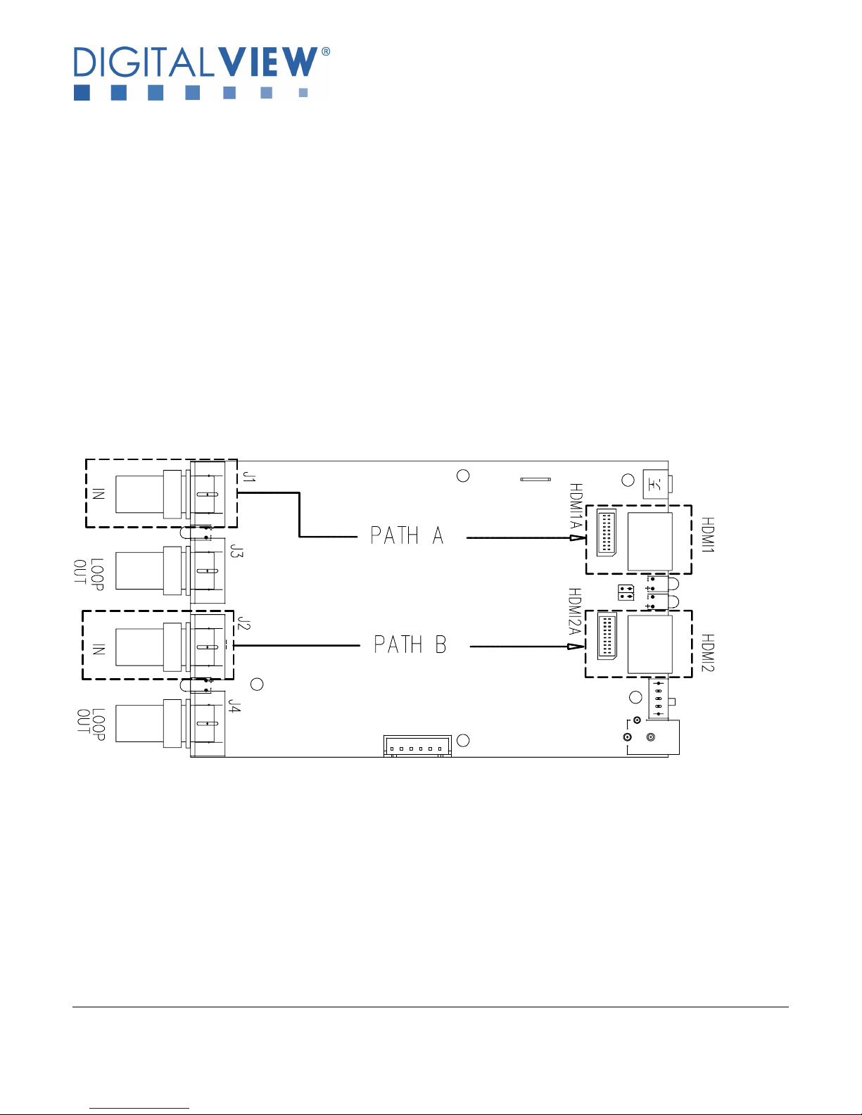
b. Dual channels input port supported.
HD-3000 supports Path A (HD-SDI input from J1 port convert to output HDMI at HDMI1/HDMI1A port) and Path B (HD-SDI input
from J2 port convert to output HDMI at HDMI2/HDMI2A port). See Figure below :
c. HD-SDI re-clock loop through output.
J1 HD-SDI input and re-clock loop through to J3 HD-SDI output. J2 HD-SDI input and re-clock loop through to J4 HD-SDI output.
d. HDMI (v1.3) x 2 output port.
Two HDMI output ports are HDMI1/HDMI1A, HDMI2/HDMI2A.
e. Stereo embedded audio support
f. On-board power on/off switch – The power on/off switch is installed on SW1.
Specifications subject to change without notice
© Digital View Ltd – Doc Ver 1.01: 7 July, 2017 Page
3 of 15
Page 4
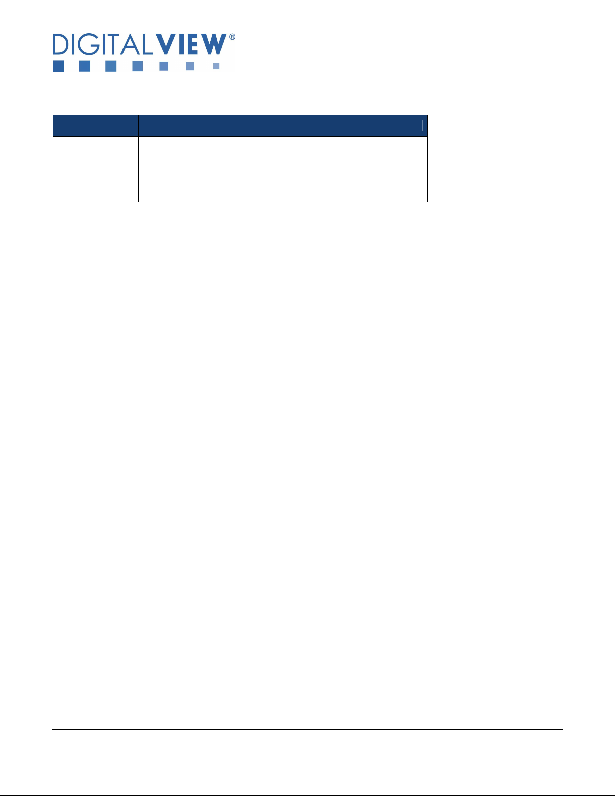
g. Status LEDs on board :
The definition of the LED1, LED2, LED3, LED4 are :
Ref Description
LED1 / LED2 Green LED on : Signal detected
Green LED Blinking : No signal detected
LED3 / LED 4 Green LED on : Signal output
Green LED off : No signal output
Specifications subject to change without notice
© Digital View Ltd – Doc Ver 1.01: 7 July, 2017 Page
4 of 15
Page 5
2. CONNECTORS, PINOUTS & JUMPERS
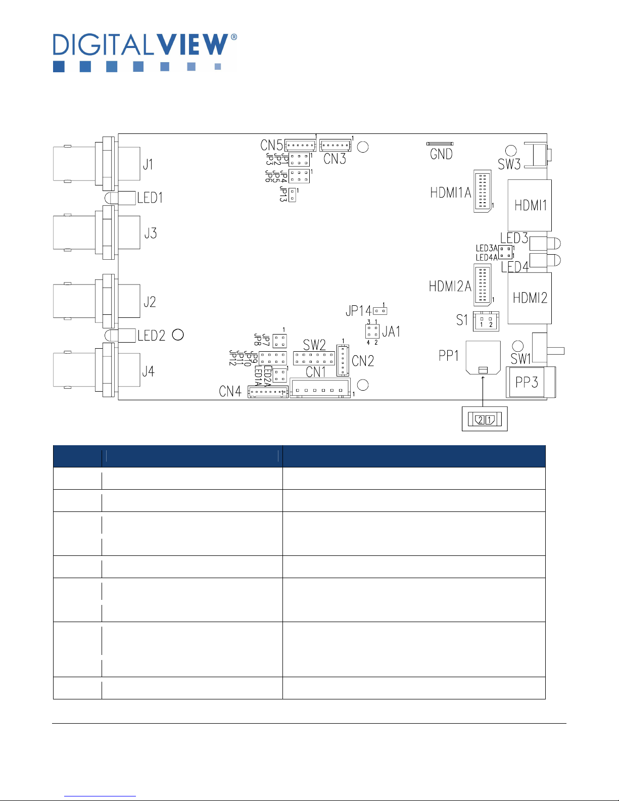
The various connectors are:
Summary: Connectors
Ref Description Type / Use
J1 SD/HD-SDI 1 Input BNC connector
J2 SD/HD-SDI 2 Input BNC connector
J3 SD/HD-SDI 1 re-clock loop through output BNC connector
J4 SD/HD-SDI 2 re-clock loop through output BNC connector
CN1 RS-232 & I2C control connector JST 6-way, B6B-XH-A (Matching type : XHP-6)
CN2 Reserved for programming use Reserved
CN3 Reserved for programming use Reserved
CN4 External I/O connector Hirose DF13-6P-1.25DSA
(Matching type : Hirose DF13-8S-1.25C)
CN5 Reserved for programming use Reserved
HDMI1 HDMI 1 Output HDMI connector
Specifications subject to change without notice
© Digital View Ltd – Doc Ver 1.01: 7 July, 2017 Page
5 of 15
Page 6
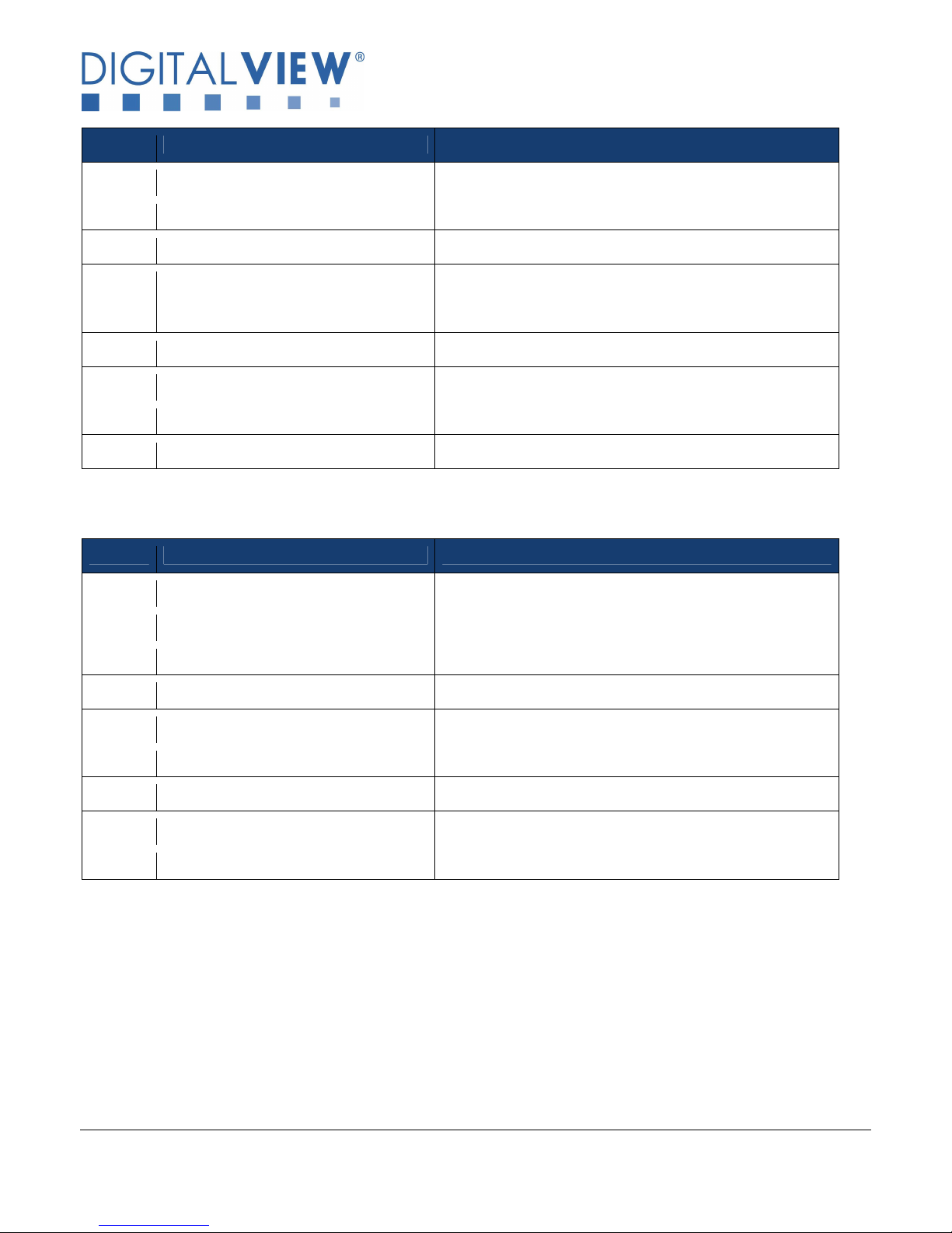
0200 compatible)
Ref Description Type / Use
HDMI2 HDMI 2 Output HDMI connector
HDMI1A Alternate HDMI 1 Output JST BM20B-SRDS (Matching type : JST SHDR-20V-S-B)
HDMI2A Alternate HDMI 2 Output JST BM20B-SRDS (Matching type : JST SHDR-20V-S-B)
PP1 Power Input (Alternate) Molex 43650-0200 compatible
(Matching connector type : Molex 43645 (Matching power cable : P/N 426013800-3)
PP3 Power Input DC power jack, 2.5mm contact pin diameter positive
S1 Alternate power on/off switch connector JST B2B-XH-A (Matching type : XHP-2)
SW1 Power on/off slide switch Slide switch
SW3 No function Reserved
Summary: Jumper settings :
Ref Purpose Note
JA1 On board +5V logic power enable 1-2 & 3-4 closed, factory set, do not remove
LED1A External LED connection Refer to pin assignment in page 7
LED2A External LED connection Refer to pin assignment in page 7
LED3A External LED connection Refer to pin assignment in page 7
LED4A External LED connection Refer to pin assignment in page 7
JP1-12 No function No function
JP13 Reserved for programming use Reserved
JP14 Reserved for programming use Reserved
SW2 No function No function
Specifications subject to change without notice
© Digital View Ltd – Doc Ver 1.01: 7 July, 2017 Page
6 of 15
Page 7
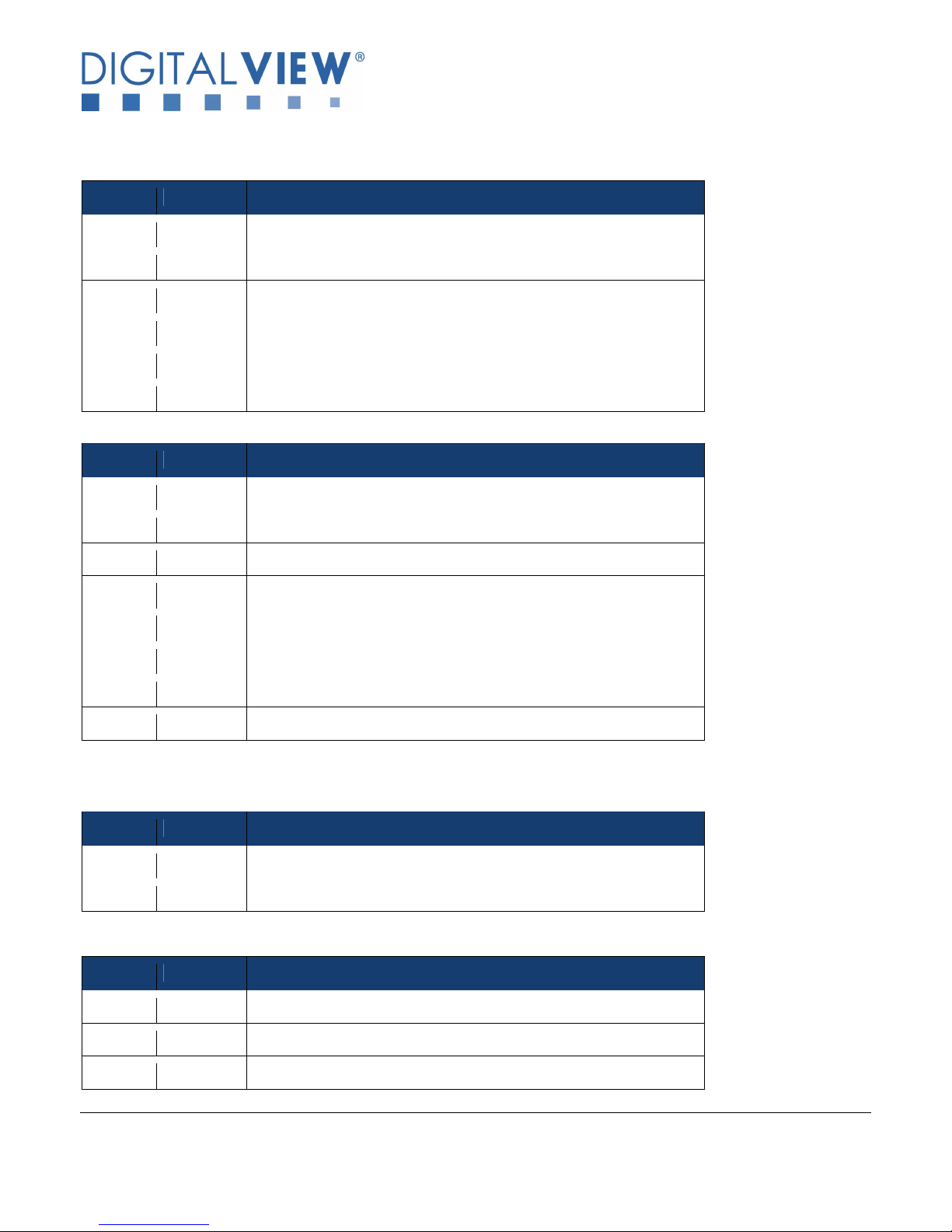
4 EXT_IP_0
Reserved
5 EXT_IP_1
Reserved
2 GND Ground
Summary : PinOuts :
CN1 – RS-232 & I2C control : JST B6B-XH-A (Matching type : XHP-6)
PIN SYMBOL DESCRIPTION
1 SCLK I2C_SCLK
2 SDATA I2C_SDATA
3 VCC +5V
4 TXD RS-232 Tx data
5 GND Ground
6 RXD RS-232 Rx data
CN4 – External I/O connector : Hirose DF13-6P-1.25DSA (Matching type : Hirose DF13-8S-1.25C)
PIN SYMBOL DESCRIPTION
1 3V3 3.3V output
2 LED3 LED3 Anode
3 LED4 LED4 Anode
6 LED1 LED1 Anode
7 LED2 LED2 Anode
8 GND LED Cathode
LED1A, LED2A, LED3A, LED4A – External LED connection
PIN SYMBOL DESCRIPTION
1 + LED Anode
2 - LED Cathode
HDMI1A – Alternate HDMI connector: JST BM20B-SRDS (Matching type : JST SHDR-20V-S-B)
PIN SYMBOL DESCRIPTION
1 GND Ground
3 RXC+ TMDS Data C+
Specifications subject to change without notice
© Digital View Ltd – Doc Ver 1.01: 7 July, 2017 Page
7 of 15
Page 8
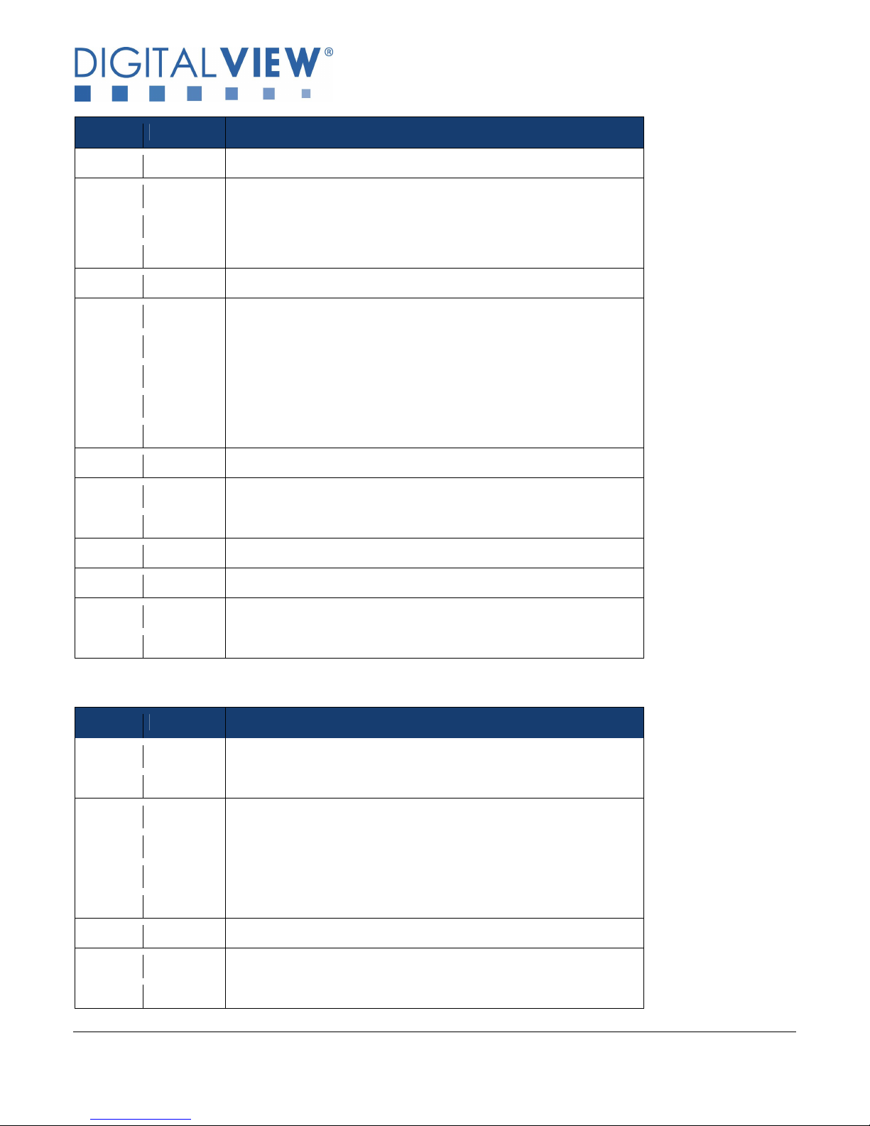
11 GND Ground
PIN SYMBOL DESCRIPTION
4 RXC- TMDS Data C-
5 RX0+ TMDS Data 0+
6 RX0- TMDS Data 0-
7 RX1+ TMDS Data 1+
8 RX1- TMDS Data 1-
9 RX2+ TMDS Data 2+
10 RX2- TMDS Data 2-
12 GND Ground
13 MSTR2_SCL Reserved
14 MSTR2_SDA Reserved
15 DDC_5V +5V power supply for DDC (optional)
16 HPD Hot plug detection
17 DDC_SCL DDC serial clock
18 DDC_SDA DDC Data
19 VCC1 VCC 5V output
20 VCC2 VCC 5V output
HDMI2A – Alternate HDMI connector: JST BM20B-SRDS (Matching type : JST SHDR-20V-S-B)
PIN SYMBOL DESCRIPTION
1 GND Ground
2 GND Ground
3 RXC+ TMDS Data C+
4 RXC- TMDS Data C-
5 RX0+ TMDS Data 0+
6 RX0- TMDS Data 0-
7 RX1+ TMDS Data 1+
8 RX1- TMDS Data 1-
9 RX2+ TMDS Data 2+
Specifications subject to change without notice
© Digital View Ltd – Doc Ver 1.01: 7 July, 2017 Page
8 of 15
Page 9
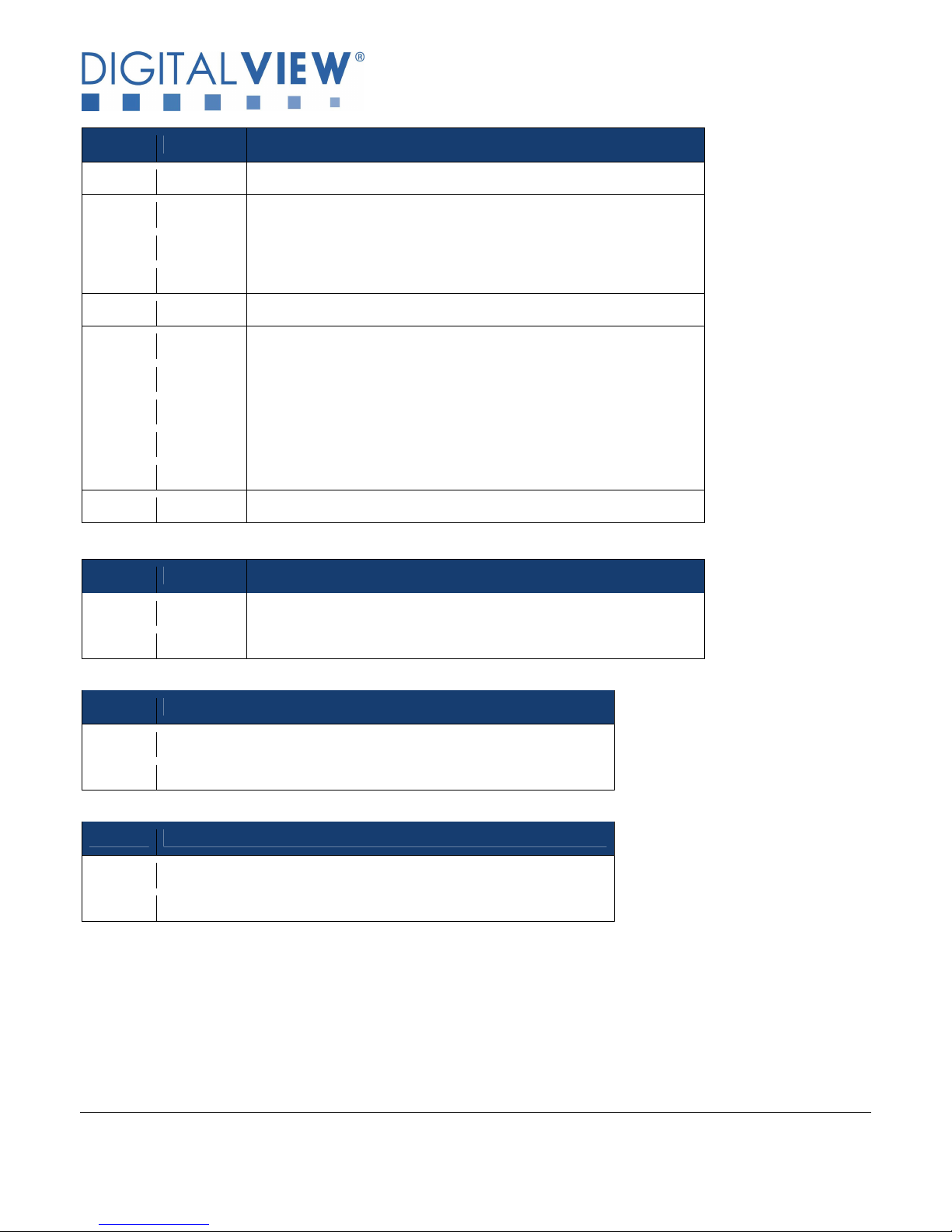
17 DDC_SCL
DDC serial clock
2 12V_OUT
+12V OUTPUT
2 Ground
PIN SYMBOL DESCRIPTION
10 RX2- TMDS Data 2-
11 GND Ground
12 GND Ground
13 MSTR2_SCL Reserved
14 MSTR2_SDA Reserved
15 DDC_5V +5V power supply for DDC (optional)
16 HPD Hot plug detection
18 DDC_SDA DDC Data
19 VCC1 VCC 5V output
20 VCC2 VCC 5V output
S1 – Alternate power on/off switch connector (Matching type : XHP-2)
PIN SYMBOL DESCRIPTION
1 12V_IN +12V INPUT
PP1 – Alternate 12VDC power supply
PIN DESCRIPTION
1 +12VDC in
2 Ground
PP3 - 12VDC power supply
PIN DESCRIPTION
1 +12VDC in
Specifications subject to change without notice
© Digital View Ltd – Doc Ver 1.01: 7 July, 2017 Page
9 of 15
Page 10
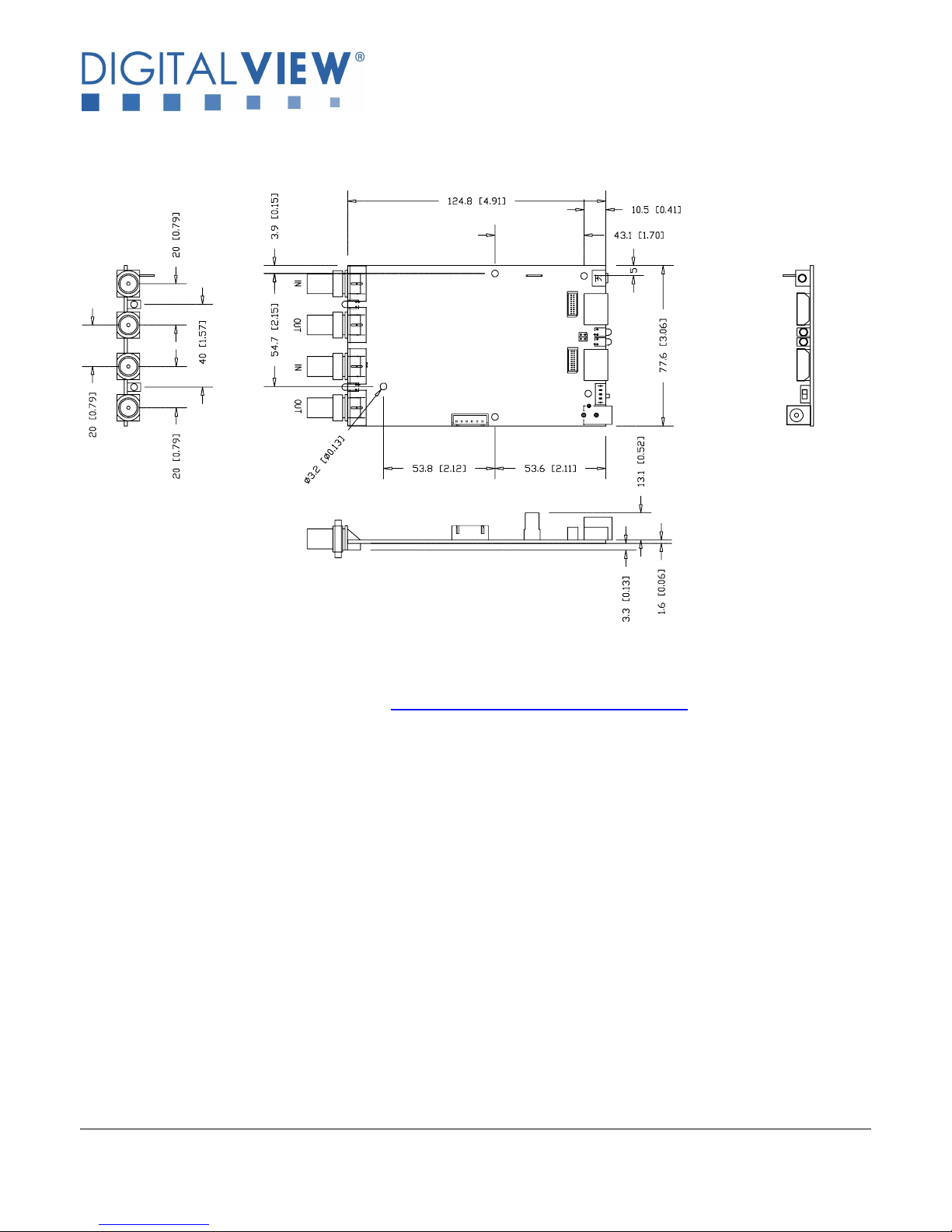
3. BOARD DIMENSIONS
Ready-made 3D Pro-E (SLDPRT) drawing files - Save time and effort for your system volumetric analysis design.
Includes jpg file previews. Please go to download at http://www.digitalview.com/accessories/hd-3000
The maximum thickness of the adaptor board is 18mm (measured from bottom of PCB to top of components, excluding the
BNC connectors. We recommend clearances of:
• 5mm from bottom of PCB - if mounting on a metal plate we also recommend a layer of suitable insulation material is
added to the mounting plate surface.
• 10mm above the components
• 3~5mm around the edges
Any of the holes shown above can be used for mounting the PCB, they are 3.2mm in diameter.
CAUTION: Ensure adequate insulation is provided for all areas of the PCB with special attention to high voltage parts
such as the inverter.
Specifications subject to change without notice
© Digital View Ltd – Doc Ver 1.01: 7 July, 2017 Page
10 of 15
Page 11
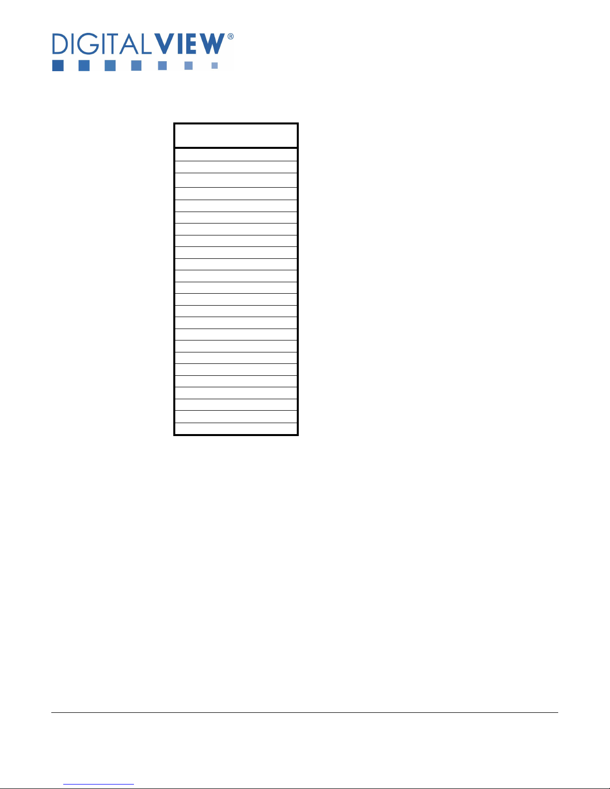
4. SIGNAL SUPPORT MODE TABLE
Mode
576i50 (PAL)
480i60 (NTSC)
720p60 (4:2:2)
720p59.94 (4:2:2)
720p50 (4:2:2)
720p30 (4:2:2)
720p29.97 (4:2:2)
720p25 (4:2:2)
1035i60 (4:2:2)
1035i59.94 (4:2:2)
1080p30 (4:2:2)
1080p29.97 (4:2:2)
1080p25 (4:2:2)
1080p24 (4:2:2)
1080p23.98 (4:2:2)
1080psf30 (4:2:2)
1080psf25 (4:2:2)
1080psf24 (4:2:2)
1080psf23.98 (4:2:2)
1080i60 (4:2:2)
1080i59.94 (4:2:2)
1080i50 (4:2:2)
1080p60 (4:2:2)
1080p50 (4:2:2)
Specifications subject to change without notice
© Digital View Ltd – Doc Ver 1.01: 7 July, 2017 Page
11 of 15
Page 12
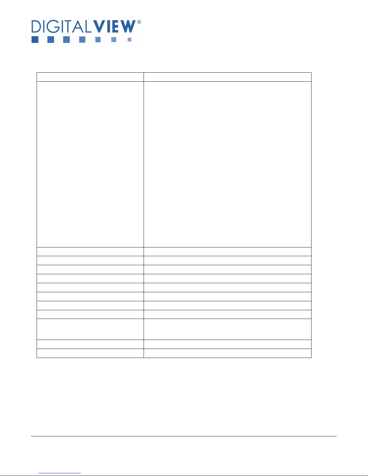
5. Specification
Supported serial interface standard SMPTE 292M, 259M-C, 424M, 425M (Level A)
Supported video mode 576i50 (PAL)
Number of channel input port supported 2
HD-SDI re-clock loop through output Yes
Output port HDMI (v1.3) x 2
Embedded audio Supported with Stereo
LEDs Status LED (Green)
On board power on/off switch Yes
Power requirement Regulated DC 12V input (2.5mm center positive)
Power consumption +12VDC ±5%, 5W
Environmental Operating temperature : 0oC to 60oC
RoHS Compliant Yes
Dimensions 124.8(W) x 77.6 (D) x 18(H) mm
480i60 (NTSC)
720p60 (4:2:2)
720p59.94 (4:2:2)
720p50 (4:2:2)
720p30 (4:2:2)
720p29.97 (4:2:2)
720p25 (4:2:2)
1035i60 (4:2:2)
1035i59.94 (4:2:2)
1080p30 (4:2:2)
1080p29.97 (4:2:2)
1080p25 (4:2:2)
1080p24 (4:2:2)
1080p23.98 (4:2:2)
1080psf30 (4:2:2)
1080psf25 (4:2:2)
1080psf24 (4:2:2)
1080psf23.98 (4:2:2)
1080i60 (4:2:2)
1080i59.94 (4:2:2)
1080i50 (4:2:2)
1080p60 (4:2:2)
1080p50 (4:2:2)
Relative humidity : 5%-95% relative humidity
(Non-condensing)
Specifications subject to change without notice
© Digital View Ltd – Doc Ver 1.01: 7 July, 2017 Page
12 of 15
Page 13

6. WARRANTY
The products are warranted against defects in workmanship and material for a period of three (3) year from the date of purchase
provided no modifications are made to it and it is operated under normal conditions and in compliance with the instruction manual.
The warranty does not apply to:
• Product that has been installed incorrectly, this specifically includes but is not limited to cases where electrical short circuit is
caused.
• Product that has been altered or repaired except by the manufacturer (or with the manufacturer’s consent).
• Product that has subjected to misuse, accidents, abuse, negligence or unusual stress whether physical or electrical.
• Ordinary wear and tear.
Except for the above express warranties, the manufacturer disclaims all warranties on products furnished hereunder, including all
implied warranties of merchantability and fitness for a particular application or purpose. The stated express warranties are in lieu of
all obligations or liabilities on the part of the manufacturer for damages, including but not limited to special, indirect consequential
damages arising out of or in connection with the use of or performance of the products.
CAUTION
Whilst care has been taken to provide as much detail as possible for use of this product it cannot be relied upon as an
exhaustive source of information. This product is for use by suitably qualified persons who understand the nature of the
work they are doing and are able to take suitable precautions and design and produce a product that is safe and meets
regulatory requirements.
LIMITATION OF LIABILITY
The manufacturer’s liability for damages to customer or others resulting from the use of any product supplied hereunder shall in no
event exceed the purchase price of said product.
TRADEMARKS
The following are trademarks of Digital View Ltd:
• Digital View
• HD-3000
Specifications subject to change without notice
© Digital View Ltd – Doc Ver 1.01: 7 July, 2017 Page
13 of 15
Page 14
7. CONTACT DETAILS
Digital View has offices in Asia, Europe and USA :
USA
Digital View Inc.
18440 Technology Drive
Building 130
Morgan Hill,
California, 95037
USA
Tel: (1) 408-782 7773 Fax: (1) 408-782 7883
EUROPE
Digital View Ltd.
6 Marylebone Passage,
London, W1W 8EX,
UK.
Tel: +44-(0)20-7631-2150 Fax: Fax: +44-(0)20-7631-2156
ASIA
Digital View Ltd
Unit 705-708, 7/F Texwood Plaza
6 How Ming Street
Kwun Tong, Hong Kong
Tel: (852) 2861 3615 Fax: (852) 2520 2987
WEBSITE
www.digitalview.com
Specifications subject to change without notice
© Digital View Ltd – Doc Ver 1.01: 7 July, 2017 Page
14 of 15
Page 15
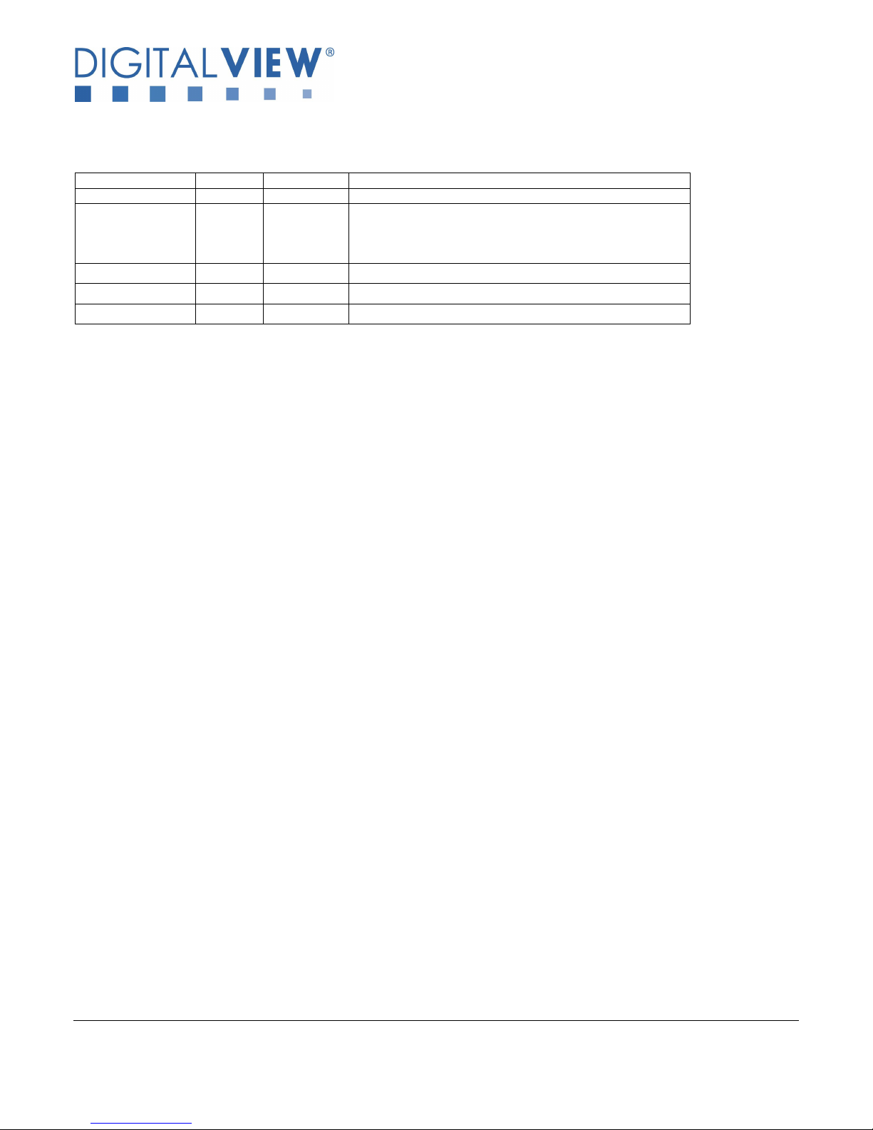
Date
Rev No.
Page
Summary
30 Sept 201
6 1.00 All First Issue
version.
Revision History
7 July 2017 1.01 7
14
15
- Correct pin definition of CN1 pin 1 & 2
- Update new Digital View HK office address
- Add document revision history section
Specifications subject to change without notice
© Digital View Ltd – Doc Ver 1.01: 7 July, 2017 Page
15 of 15
 Loading...