

Page 1
DVR-810
Dual Tuner / DVB-T High Definition
Digital Video Recorder
Ver. 1.0
©
2006-2007 Digitalview Australia
Owner’s Manual
Page 2

For addendums or supplementary information to this manual please refer to our Support page at
digitalview.com.au.
Page 3

The DVR-810 has been designed and
manufactured to assure personal safety. Improper
use can result in electric shock or re hazard. The
safeguards incorporated in this unit will protect
you if you observe the following procedures for
installation, use, and servicing.
This unit does not contain any parts that can be
repaired by the user.
DO NOT REMOVE THE CHASSIS COVER, OR YOU
MAY BE EXPOSED TO DANGEROUS VOLTAGES.
REFER SERVICING TO QUALIFIED SERVICE
PERSONNEL ONLY.
1. Read these instructions. - All these safety
and operating instructions should be read
before the product is operated.
2. Keep these instructions. - The safety,
operating and use instructions should be
retained for future reference.
3. Heed all warnings. - All warnings on the
product and in the operating instructions
should be adhered to.
4. Follow all instructions. - All operating and
use instructions should be followed.
5. Do not use this apparatus near water. – For
example: near a bath tub, wash bowl, kitchen
sink, laundry tub, in a wet basement; near a
swimming pool; etc.
IMPORTANT SAFETY INSTRUCTIONS
CAUTION: PLEASE READ AND OBSERVE ALL WARNINGS AND INSTRUCTIONS IN THIS OWNERS MANUAL
AND THOSE MARKED ON THE UNIT. RETAIN THIS GUIDE FOR FUTURE REFERENCE.
6. Clean only with dry cloth. – Unplug this
product from the wall outlet before cleaning.
Do not use liquid cleaners.
7. Do not block any ventilation openings. Install
in accordance with these instructions. Slots
and openings in the cabinet are provided
for ventilation, to ensure reliable operation
of the product, and to protect it from overheating. The openings should never be
blocked by placing the product on a bed,
sofa, rug or other similar surface. This product
should not be placed in a built-in installation
such as a bookcase or rack unless proper
ventilation is provided.
8. Do not install near any heat sources such
as radiators, heat registers, stoves, or other
apparatus (including ampliers) that produce
heat.
9. Protect the power cord from being walked on
or pinched, particularly at plugs, convenience
receptacles, and the point where they exit
from the apparatus.
10. Only use attachments/accessories specied
by Digitalview.
11. Unplug the DVR-810 and antenna lead during
severe lightning storms or when unused for
long periods of time.
Page 4

Table of Contents
IMPORTANT SAFETY INSTRUCTIONS
Introduction....................................................................................... 1
User Convenience Summary...................................................................... 2
Features of the DVR-810.................................................................. 2
Technical Performance Summary .............................................................3
Package Contents ............................................................................4
Digital Television - Antennas ..........................................................5
What You Need to Know............................................................................. 5
Interlaced (i) and Progressive (p) Scanning .............................................6
Digital TV Transmission Formats ..............................................................6
Television Signal Formats in Australia ..........................................6
Analog TV vs Digital TV ..............................................................................6
DVR-810 Video Output Resolutions................................................ 7
Standard and High Denition Video Outputs ...........................................7
Aspect Ratios.................................................................................... 8
Basic Information on Aspect Ratios.......................................................... 8
Front Panel Overview..................................................................... 10
Front Panel Displays and Buttons................................................ 11
Standby Button.......................................................................................... 11
Information Display................................................................................... 11
Operating Status Indicators .....................................................................11
Transport Controls and Navigation Buttons................................ 12
Rear Panel Overview...................................................................... 13
Remote Control Unit ...................................................................... 14
Button Denitions 1 ..................................................................................14
Button Denitions 2 ..................................................................................15
Button Denitions 3 ..................................................................................16
TV Connection using an Analog TV ........................................................17
Connection Diagram - Video and S-Video
(Standard Denition Analog Video).............................................. 17
Connection Diagram - Component Video YPbPr
(High Denition Analog Video)...................................................... 18
Connection using a Flat Panel Display with Component Inputs ..........18
Connection Diagram - RGB Video
(High Denition Analog Video)...................................................... 19
Connection using Flat Panel Display with RGB Inputs .........................19
Connection Diagram - HDMI
(High Denition Multimedia Interface).......................................... 20
Connection using a High Denition Flat Panel Display with HDMI ......20
RS232 and Ext IR Connections ..................................................... 21
Control Automation and External IR Ports .............................................21
Operational Introduction................................................................ 22
Operational Introduction ..........................................................................22
Using the STBY Button........................................................................... 22
Tuning the DVR-810 for Digital TV Reception ........................................23
Watching Live TV and Changing Channels ............................................24
INFO Function. .......................................................................................25
Recording Using - On-Demand, Timer, EPG or Timeshifting................ 27
To Record a Program On-Demand. ........................................................27
Using the Channel Browser to Record ...................................................28
Recording Programs Using the Schedule Timers................................... 29
Using the EASY TIMER Function for Scheduled Recordings................. 29
Using the TIMER REC Function for Scheduled Recordings................... 30
Using the EPG for Scheduled Recordings..............................................31
Using Timeshift to Record a Current Program........................................ 32
Recording with Timeshift ........................................................................32
Playback..................................................................................................... 33
The REC LIST Button.............................................................................33
Playback a Recorded Title...................................................................... 33
Deleting a Single Recorded Title Using the Record Browser..................33
Playback a Recorded Title Using Genre ................................................34
Transport and Trick Control Modes. .......................................................35
Chase and Chase Play...........................................................................35
Operation of the Trick and Transport Control Modes.............................35
Bookmarking During Recording or Playback..........................................38
Supplementary Operations. .....................................................................39
Photo Capture and Playback..................................................................39
PIP (picture-In-Picture) ...........................................................................40
Using PIP with Live TV ...........................................................................40
Using PIP with Live TV and a Recorded Title......................................... 40
CC/TT (Closed Captions/Teletext) ..........................................................41
RD/TV.....................................................................................................41
The MAIN MENU ........................................................................................42
The MENU Button...................................................................................42
The Channel Browser. ..............................................................................43
Viewing ...................................................................................................43
Recording ...............................................................................................43
Viewer Preferences ...................................................................................44
Lock a Channel/Service –....................................................................... 44
To Unlock a Channel/Service –............................................................... 44
Viewing a Locked Channel/Service – .....................................................45
Delete a Channel/Service.......................................................................45
Reassigning the Channel Group Buttons (BLUE Buttons) .....................45
Installation .................................................................................................47
Installation - Auto Scan........................................................................... 47
Installation - Add Carrier.........................................................................47
Frequency............................................................................................... 48
Installation - Delete Carrier.....................................................................48
Setup ..........................................................................................................49
TV Settings .............................................................................................49
TV Settings - Aspect Ratio......................................................................49
TV Settings – Video Format....................................................................50
TV Settings – Audio Setting.................................................................... 51
Password Setting.................................................................................... 52
Factory Default .......................................................................................52
Time Setting............................................................................................53
Parental Guidance..................................................................................54
OSD Settings..........................................................................................55
OSD Settings - Transparency................................................................ 55
OSD Settings - Banner Timeout ............................................................55
OSD Settings - VFD Brightness.............................................................56
OSD Settings - Event Notication.......................................................... 56
Signal Strength.......................................................................................... 57
Disc Navigator ...........................................................................................58
Play......................................................................................................... 58
Sort .........................................................................................................58
Genre...................................................................................................... 59
Rename ..................................................................................................60
Delete .....................................................................................................60
Lock ........................................................................................................61
Edit..........................................................................................................62
Editing a Recorded Title .........................................................................63
Book Mark...............................................................................................64
Merge......................................................................................................65
Timer Recordings...................................................................................... 66
Photo Viewer.............................................................................................. 67
Conguring the Photo Viewer ................................................................67
Adjusting the Preset Time ......................................................................67
Delete a Photo........................................................................................67
Disc Setup.................................................................................................. 68
Using Disc Setup ....................................................................................68
HDD Information.....................................................................................68
HDD Format............................................................................................68
Power Saving..........................................................................................69
Forward Skip...........................................................................................69
Reverse Skip ..........................................................................................70
About..........................................................................................................71
Specication ................................................................................... 72
Page 5

Introduction 1
Thank you for purchasing the Digitalview DVR-810 Dual Tuner, High Denition Digital
Video Recorder. This manual describes the everyday operation and advanced recording
functionality of your DVR-810. The DVR-810 uses a series of comprehensive on-screen
displays and menus to allow full viewing, recording and playback of standard and high
denition content. The most common functional controls for viewing, recording and
playback can be executed using specic buttons on the RCU, including some limited
functionality using the buttons on the front panel.
In most cases your DVR-810 needs minimal set-up. Refer to the separate Quick-Start
Guide for more information.
Should you experience any difculties with the operation of your DVR-810, please
consult the relevant section of this manual, or alternatively go to our web page for
support at www.digitalview.com.au.
Introduction
DVB and the DVB logo are registered trademarks of the DVB Project.
“HDMI,” the HDMI logo and High-Denition Multimedia Interface are trademarks or registered trademarks
of HDMI Licensing LLC.
“Dolby” and the double-D symbol is a trademark of Dolby Laboratories.
Crestron® is a registered trademark of Crestron Electronics.
AMX is a trademark of AMX Corporation.
“TosLink” is a registered trademark of Toshiba Corporation.
All other trademarks that may appear in this manual are the property of their respective owners.
For any on-going improvement of this product, the specication and/or contents are subject to change
without prior notice.
©2006 Control Dynamics Pty. Ltd. / Digitalview Australia. All rights reserved.
Page 6

2 Introduction
Introduction 3
Features of the DVR-810
User Convenience Summary
On-Screen User Menus
Simple to use menus to congure the DVR-810.
Remote Control Unit
Full function Remote Control Unit for viewing live TV, recording and playback.
Channel Groups “Hot-keys”
Selection of all major Australian broadcasters by way of a pre-assigned “Hot-key” buttons on the Remote
Control Unit. Hot-keys can be re-assigned for any regional area service and/or used to disable an active
service from any individual Hot-key.
INFO Button
Specic information on the current status of the DVR-810. whether receiving, recording and/or playing
back.
Advanced Trick Modes
Variable speed Fast Forward and Rewind, Bi-directional and Variable Speed Slow Motion, JUMP
One Touch Recording with Variable Time Extension
Record a program and choose between the default program time or variable times
Recording Program Event Timers
Thirty two event program timers can be used to record your favourite programs. Unattended recording
schedule can be set by way of a 24 hour program timer, Extended Program Timer or EPG based timer.
Multiple Monitor Connection
Four standard or widescreen TV monitors can be connected to the DVR-810 for concurrent program
viewing.
Video Editing
Simple video editor to delete scenes in a video title.
Video Merge
Combine two video titles into one
Dynamic Bookmarks
Set specic scene reference points when recording or while playing back a video title. All Bookmarks can
be edited.
Page 7

Introduction 3
Picture Viewer
Allows a simple slideshow of captured video frames. Frames are captured and stored during recording or
playback.
Control Interface
The RS232C service and control port is utilised for interfacing to popular Home Control and Automation
Systems.
Technical Performance Summary
Tuner Implementation
High performance dual tuner design.
Independent Aspect Ratio Control
Separate adjustment of aspect ratios for standard and/or high denition screen formats when used with
multiple TV monitors.
High Capacity Hard Disc Drive
Drive capacities of 320GB and upwards.
Standard and High Denition Viewing and Recording Resolutions
The DVR-810 supports 1080i, 720p, 576p and 576i resolutions .
TV Monitor Connections
Multiple video outputs are provided for connection to most TV monitors. These include, Composite
Baseband Video, S-Video, Component (Y,Pb,Pr), RGB and HDMI.
Multiple Audio Outputs
The DVR-810 supports one stereo analog audio output and two digital (coaxial and optical) audio
outputs for connection to Dolby Digital compatible receivers / home theatre systems.
Software Upgrades
Over the Air Download for unattended software updates. A serial port is also included for connection to
a PC or Serial Key Module.
USB2
Connection for future product peripherals.
Thermal Protection
Continuous monitoring of the internal temperature of the DVR-810, protects against any unexpected
problems that may be related to installation or other thermal effects.
Page 8
4 Introduction Overview 5
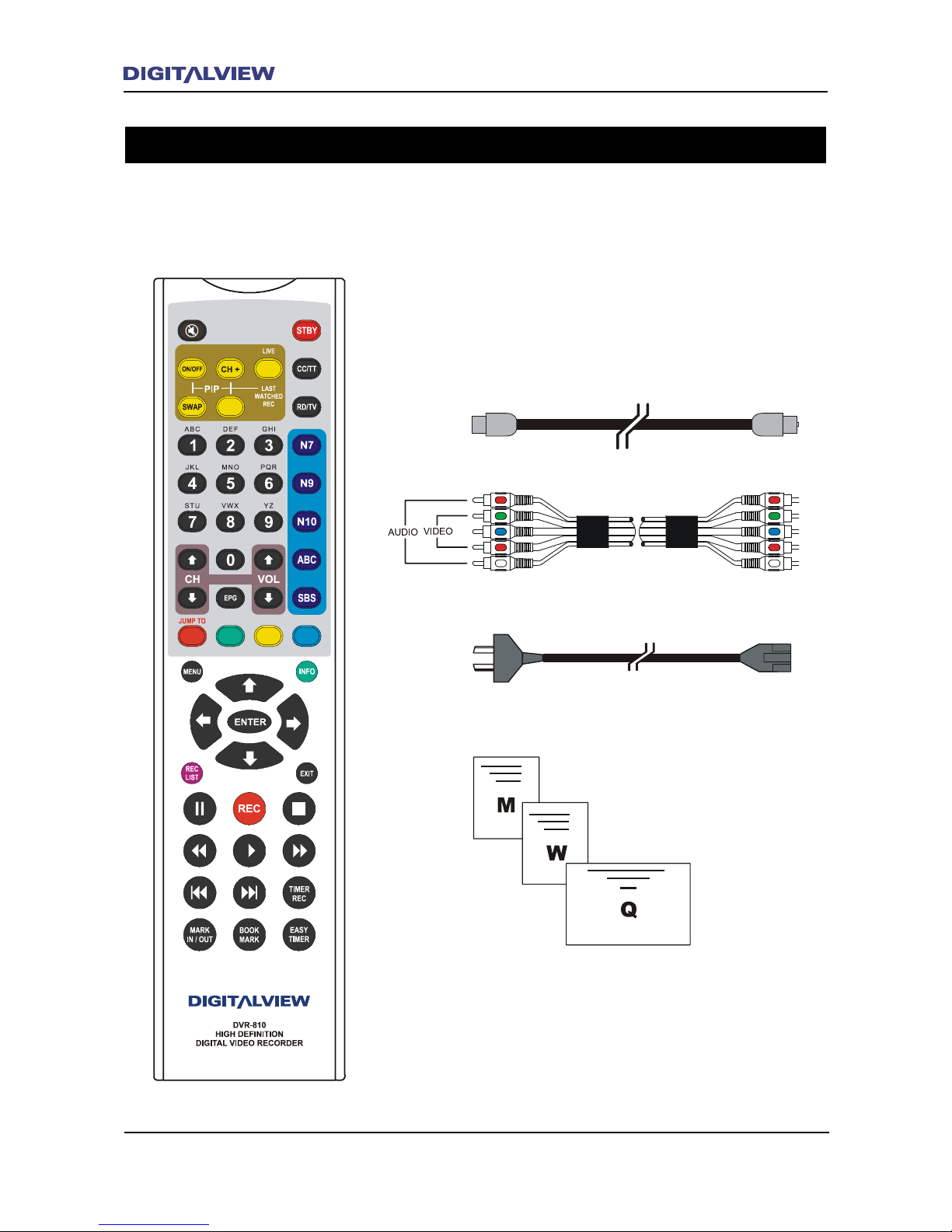
Package Contents
Antenna Cable
Component (YPbPr) Cable
Power Cable
Remote Control Unit
Owners Manual
Warranty Registration Card
Quickstart Guide
The following items are included with your DVR-810.
Page 9

Digital Television - Antennas
What You Need to Know
When upgrading to digital TV, it is important to consider the suitability and condition of your existing
antenna and feeder cable.
Many older antennas may not cover the digital TV channels in use in your area. A competent antenna
installer can advise you on your specic requirements.
The feeder cable may also need upgrading. For best results RG-6 type cable with dual or quad screening
should be used.
The antenna location and height may also need to be considered. Antennas located in roof cavities may
be very close to electrical wiring. This may lead to impulse noise drop-outs when switching lights or
other electrical appliances.
If you live in a fringe reception area and have had a mast head amplier there are a number of issues to
consider.
1. Is the amplier specied suitable for digital TV. Older ampliers maybe unsuitable.
2. Are the digital signal levels sufciently high to do without the amplier. Only use a mast head
amplier if it is absolutely necessary.
3. If you must have a mast head amplier, make sure it has variable gain and only use the amount
needed. Setting ampliers to full gain makes them prone to overload from electrical noise and radio
frequency signals. The result can be frequent dropouts of the digital TV service.
Page 10
6 Overview
Overview 7
Television Signal Formats in Australia
Analog TV vs Digital TV
The Australian Standard for both analog and digital TV transmission is based on variations of the
European Standard of PAL and DVB.
All analog TV broadcasts are transmitted in the PAL-B/G format while all digital TV broadcasts are
transmitted using the DVB-T (T - Terrestrial) standard. Both analog and digital transmissions utilise VHF
and UHF bands
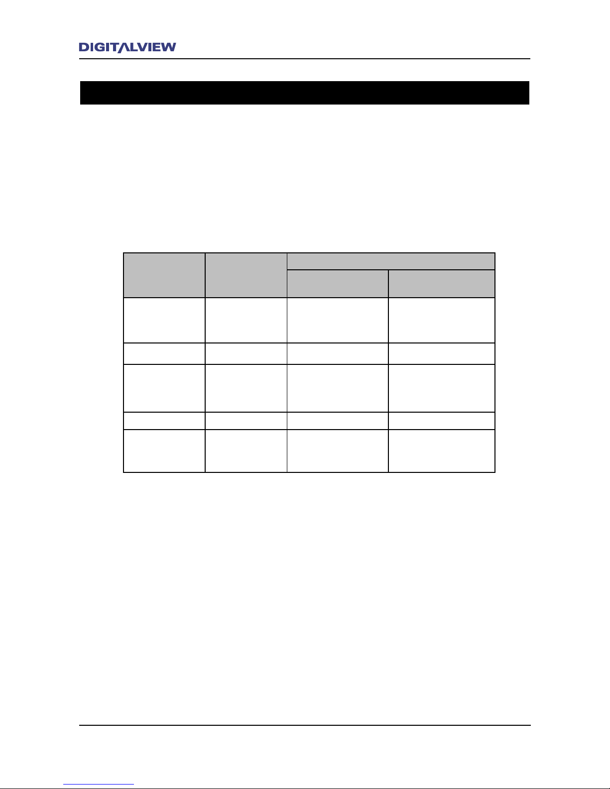
The following table shows the basic differences between the Australian analog and digital TV
transmission formats.
Format Analog PAL
DVB-T Digital
Standard
Denition
High Denition
Active Lines /
Active Pixels
625 lines 576 x 720
576 x 720
720 x 1280
1080 x 1920
Aspect Ratio 4:3 4:3 or 16:9 4:3 or 16:9
Resolution/s 576i 576i (interlaced)
576p (progressive)
720p (progressive)
1080i (interlaced)
Video Raster MPEG-2 MPEG-2
Audio Analog Stereo
MPEG (2 ch)
Dolby Digital 2 / 5:
1 ch
MPEG (2 ch)
Dolby Digital 2 / 5:
1 ch
Interlaced (i) and Progressive (p) Scanning
Interlaced format shows half of an image (on the odd rows of pixels) every ftieth of a second, and then
shows the other half (on the even rows) the next ftieth. Therefore, it takes one twenty fth of a second
for a complete frame, giving a frame rate of 25 frames per second.
Progressive format shows one complete video image every ftieth of a second, so the effective frame
rate is twice as high as interlaced - 50 frames per second. In general, the progressive format gives a
“smoother” quality picture than interlaced and specically on larger screens.
Digital TV Transmission Formats
The current Australian Standard for broadcasting digital TV is set at four formats. These are:
576i - Standard Denition: 576 x 720 pixels at a frame rate of 25 complete frames per second.
576p - High Denition: 576 x 720 pixels at a frame rate of 50 complete frames per second.
720p - High Denition: 720 x 1280 pixels at a frame rate of 50 complete frames per second.
1080i - High Denition: 1080 x 1920 pixels at a frame rate of 25 complete frames per second.
Page 11
Overview 7
DVR-810 Video Output Resolutions
Standard and High Definition Video Outputs
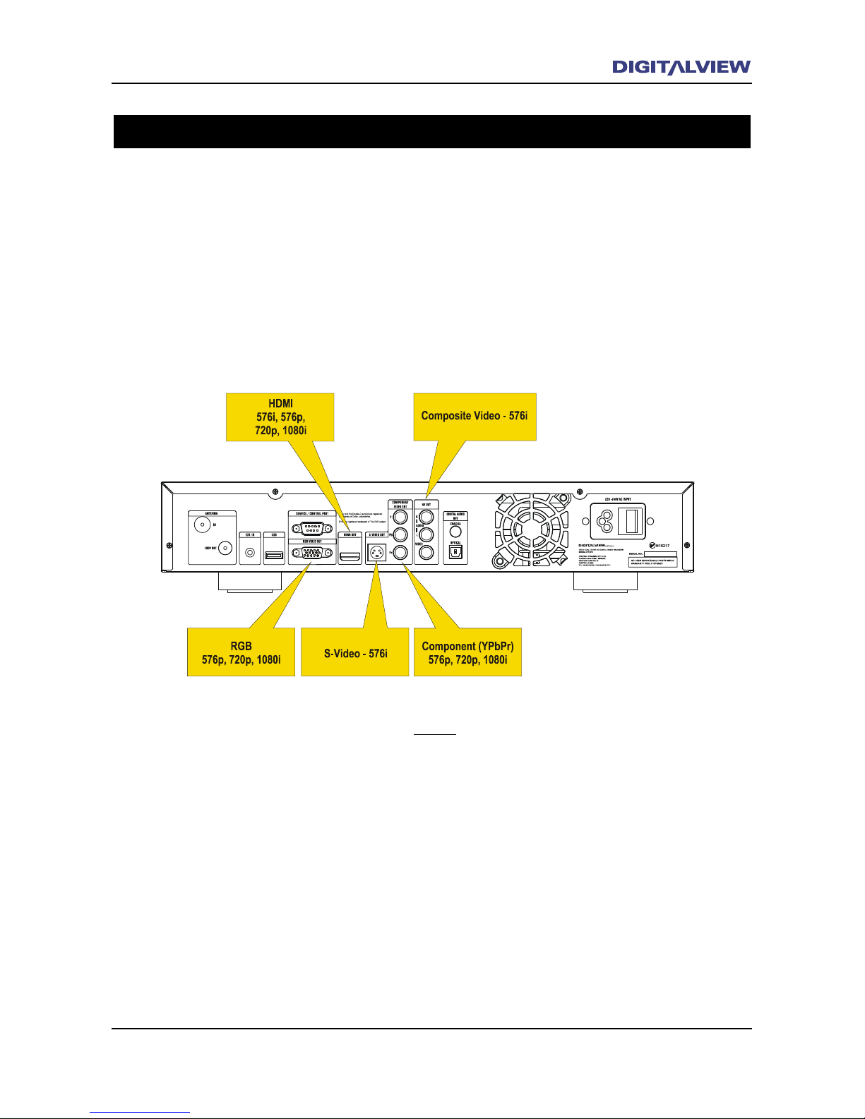
The DVR-810 can connect to all TV monitors that support either 576i, 576p, 720p or 1080i resolutions.
When selecting the video output resolution for your TV monitor, all digital TV input formats are
converted to the selected video output resolution. (Refer to the section in System Settings - Video).
Ensure that your TV monitor supports one or more of the resolutions - 576i, 576p, 720p or 1080i. If
necessary and only when connected to Component, RGB or HDMI, use the EXIT button on the front panel
of the DVR-810 to select the appropriate video output resolution.
Note:
• Component and RGB video outputs cannot
be used simultaneously.
Page 12
8 Overview
Overview 9
Basic Information on Aspect Ratios
Your television screen has a certain physical
width and height which is technically referred to
as “aspect ratio”.
There are currently two variations for television
aspect ratios. These are 4:3 and 16:9.
Televisions with a 4:3 aspect ratio were primarily
designed for analog television where most
programs were broadcast in a 4:3 screen format.
With the introduction of DVDs and digital
terrestrial TV, the aspect ratio changed to meet
the requirements for a wider viewing format. This
wider viewing format typically increased the
size of picture that could be displayed in a video
frame. The of cial widescreen format for digital
TV was therefore set as 16:9 which covered both
Standard and High De nition broadcasts.
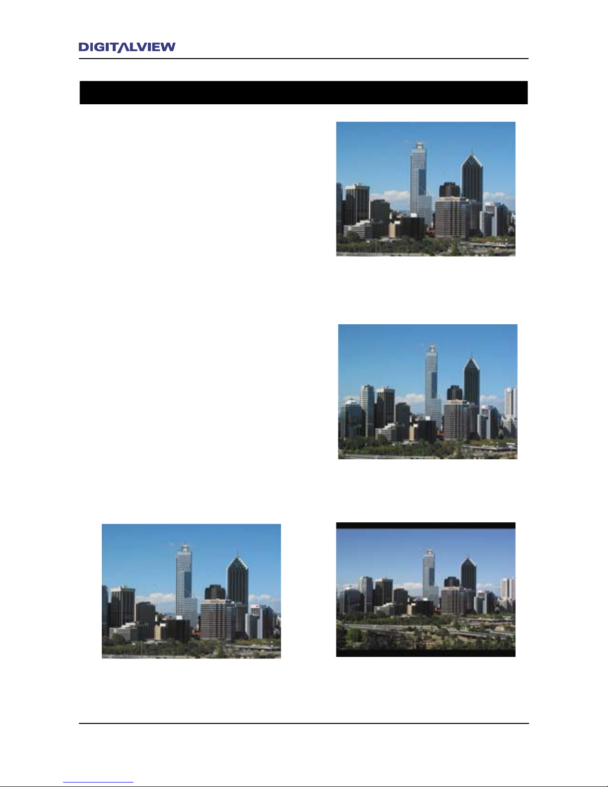
The following diagrams illustrate the variations
that are possible from digital TV broadcasts using
both 4:3 and 16:9 screen formats. The DVR-810
allows for the choice of aspect ratios regardless
of the screen format.
Received digital TV broadcast in 4:3
format. DVR-810 aspect ratio set to 4:3.
Received digital TV broadcast in 16:9
format. DVR-810 aspect ratio set to 4:3.
Received digital TV broadcast in 16:9
format. DVR-810 aspect ratio set to 4:3
Letter-box
Television with 4:3 Screen Format
Received digital TV broadcast in 16:9
format. DVR-810 aspect ratio set to 16:9
Aspect Ratios
Page 13
Overview 9
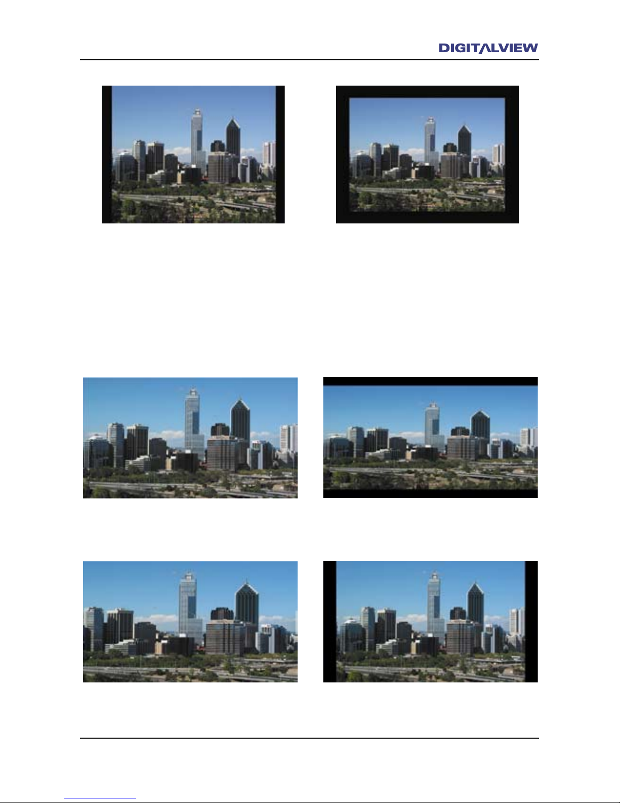
Received digital TV broadcast in 4:3
Pillar-box format. DVR-810 aspect ratio
set to 4:3. This type of display format
is sometimes referred to as “Postage-
stamp”
Received digital TV broadcast in 16:9 format.
DVR-810 aspect ratio set to 16:9.
Television with 16:9 Screen Format
Received digital TV broadcast in 16:9 format.
DVR-810 aspect ratio set to 4:3.
Received digital TV broadcast in 16:9 format.
DVR-810 aspect ratio set to 4:3 Letter-box.
Received digital TV broadcast in 4:3 Pillar-box
format. DVR-810 aspect ratio set to 16:9.
Received digital TV broadcast in 4:3
Pillar-box format. DVR-810 aspect ratio
set to 16:9.
Note:
• A Pillar-box is where a 4:3 program is
framed with a black bar on the left and
right sides to create a 16:9 video frame.
Page 14
10 DVR-810 Front and Rear Panel
DVR-810 Front and Rear Panel 11
Front Panel Overview
Page 15
DVR-810 Front and Rear Panel 11
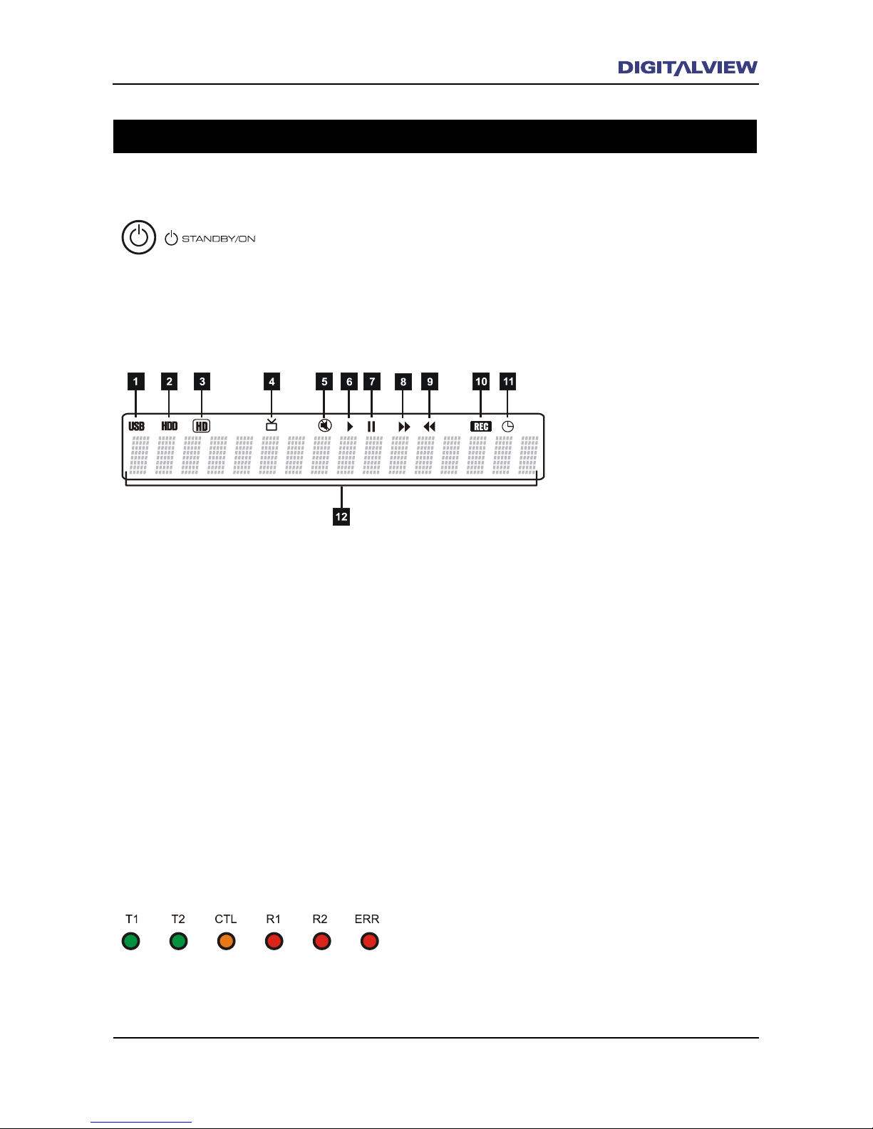
T1 and T2 illuminate Green when one or both internal
Tuners are active. CTL illuminates Orange whenever a
button on the RCU is pressed. R1 and R2 illuminate Red,
when the DVR-810 is recording one (R1) or two (R2)
programs. ERR illuminates Red when an error in receiving
is detected.
1. For future implementation of external devices with USB2 compatibility.
2. Indicator is On when recording or playing back from the Hard Disc Drive.
3. Indicator is On when the program being viewed, recorded or playing back, is in High Denition.
4. Indicator is On for TV Signal Reception.
5. Indicator is On when Audio Mute is active.
6. Indicator is On during Playback or Chase modes.
7. Indicator is On during Timeshift or while Paused in Playback mode.
8. Indicator is On during Recording or Playback and only if the Fast Forward function has been
activated.
9. Indicator is On during Recording or Playback and only if the Fast Rewind function has been
activated.
10. Indicator is On while Recording.
11. Indicator in On when the Timer Scheduled Recording option is set.
12. Alpha-numeric character display shows information relevant to TV reception, recording and playback
functions.
Front Panel Displays and Buttons
When the Standby / ON button is pressed three modes of operation are
possible. Illuminates Blue when switched ON. Illuminates Red when
switched OFF. Flashes Red when recording and/or the Timer Scheduled
Recording is active.
Standby Button
Information Display
Operating Status Indicators
Page 16
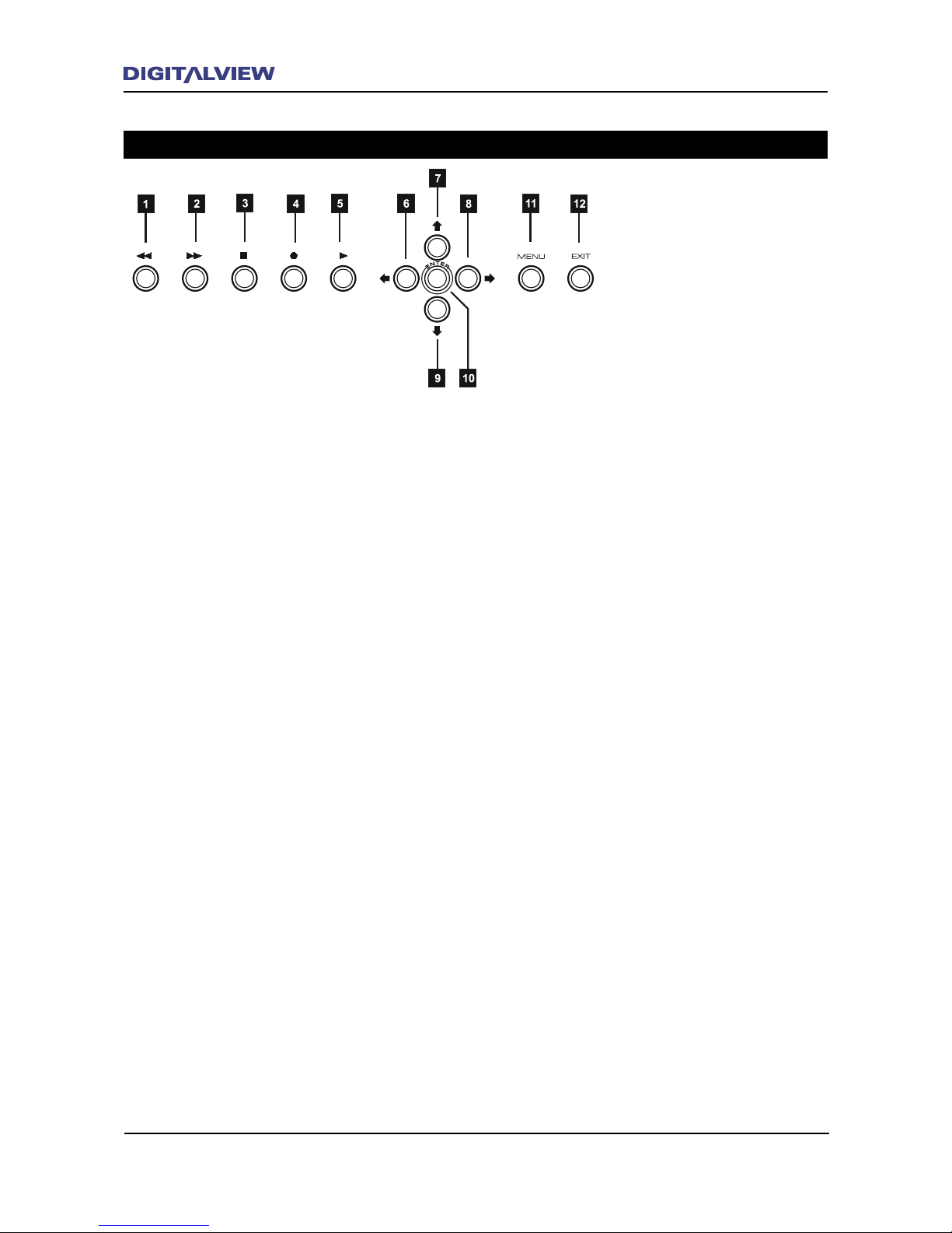
12 DVR-810 Front and Rear Panel
DVR-810 Front and Rear Panel 13
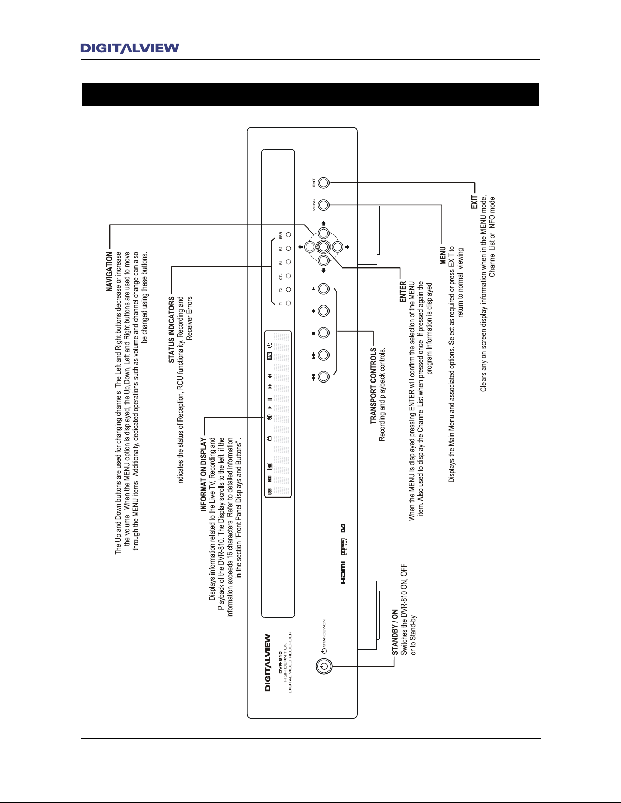
1. FAST REWIND during Playback. Multiple speed selection from x1 to x5 normal playback speed.
2. FAST FORWARD during Playback. Multiple speed selection from x1 to x5 normal playback speed.
3. STOP Recording or Playback.
4. Start RECording the program currently being viewed.
5. PLAY displays the REC LIST. Select a Program Title from the REC LIST and press ENTER.
6. Navigation button - Scroll or Move LEFT when a Menu option is selected. Also used to decrease the
audio volume level -
7. Navigation button - Scroll or Move UP when a Menu option is selected. Also used to change the
channel/service.
8. Navigation button - Scroll or Move RIGHT when a Menu option is selected. Also used to increase
the audio volume level
9. Navigation button - Scroll or Move DOWN when a Menu option is selected. Also used to change the
channel/service
10. ENTER conrms and applies any selected Menu option. ENTER also activates the Channel Browser.
11. MENU displays the Main Menu options. Select a menu option from the Main Menu list and press
ENTER.
12. EXIT is used to clear all on-screen Menus or Sub-menus including cancellation of any existing input
values or setup options.
Transport Controls and Navigation Buttons
Page 17
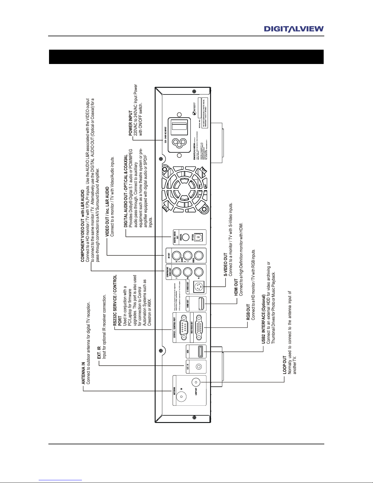
DVR-810 Front and Rear Panel 13
Rear Panel Overview
Page 18
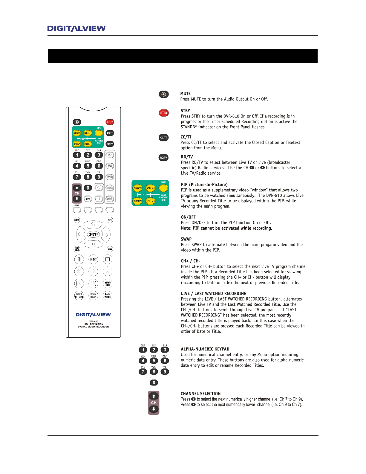
14 Remote Control Unit
Remote Control Unit 15
Remote Control Unit
Button Definitions 1
Page 19
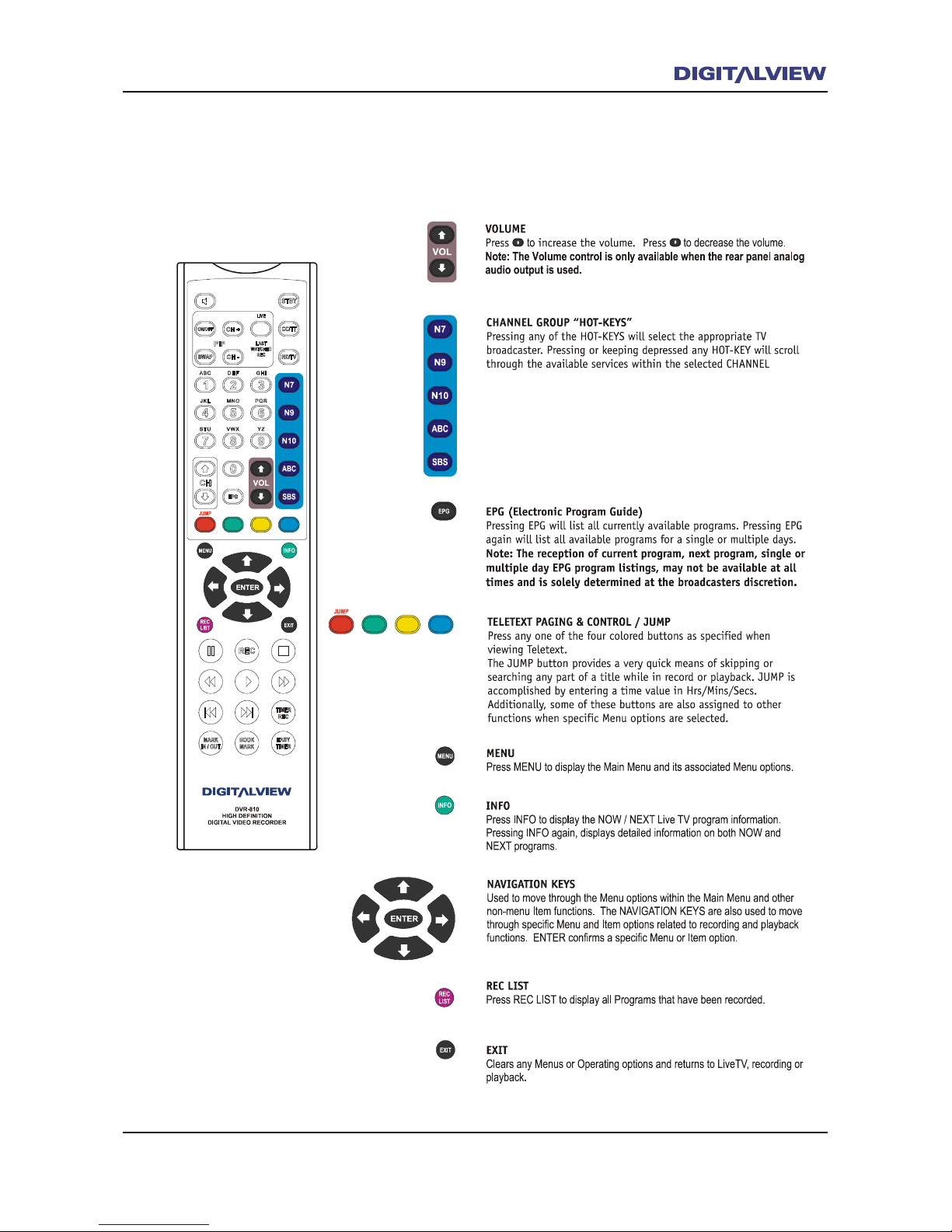
Remote Control Unit 15
Button Definitions 2
Page 20
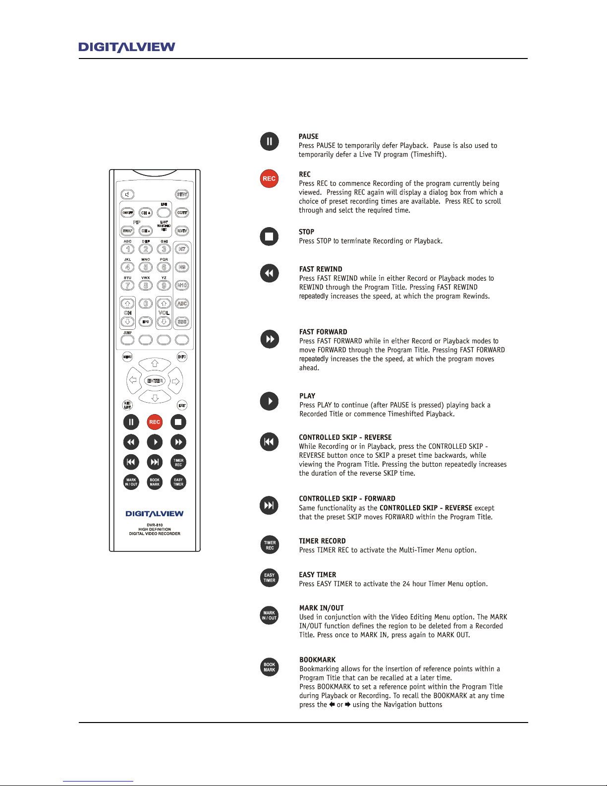
16 Remote Control Unit Installation and Setup 17
Button Definitions 3
Page 21
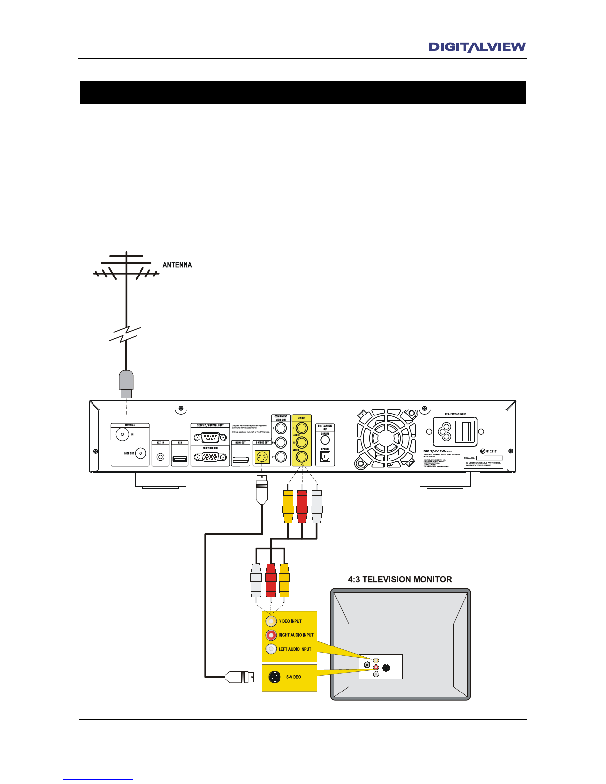
Note:
• S-Video provides a better quality picture than conventional (composite) video.
TV Connection using an Analog TV
The connection diagram show below is used in some situations where a standard denition or analog
TV will be connected to the DVR-810. Ensure that power to both the DVR-810 and TV is OFF before any
connections are made.
Connection Diagram - Video and S-Video (Standard Denition Analog Video)
Page 22
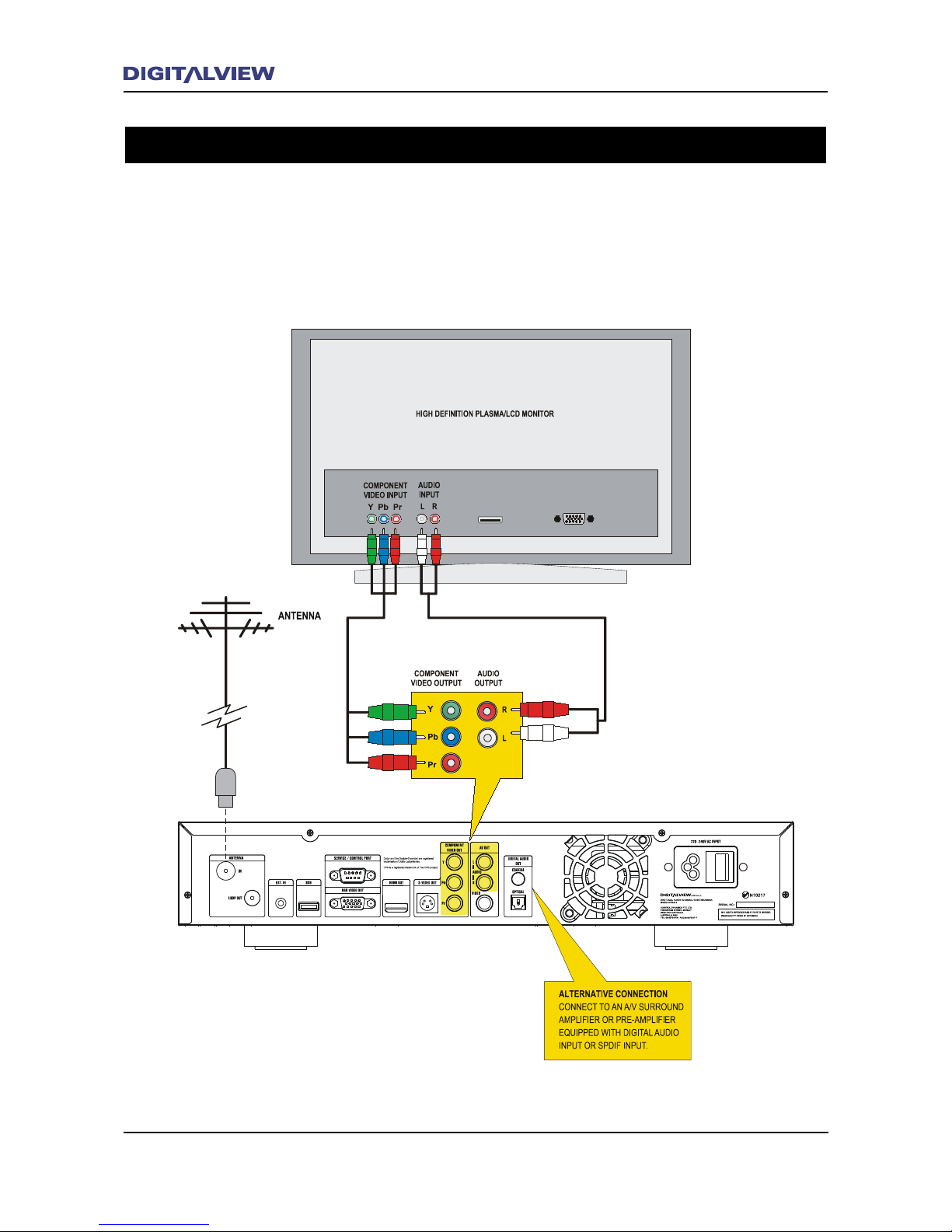
18 Installation and Setup
Installation and Setup 19
Connection Diagram - Component Video YPbPr (High Denition Analog Video)
Connection using a Flat Panel Display with Component Inputs
Use this type of connection with a high denition analog TV monitor or Flat Panel Display. If an analog
TV monitor is used it must support either 576p, 720p or 1080i resolutions.
Ensure that power to both the DVR-810 and TV is OFF before any connections are made.
Page 23
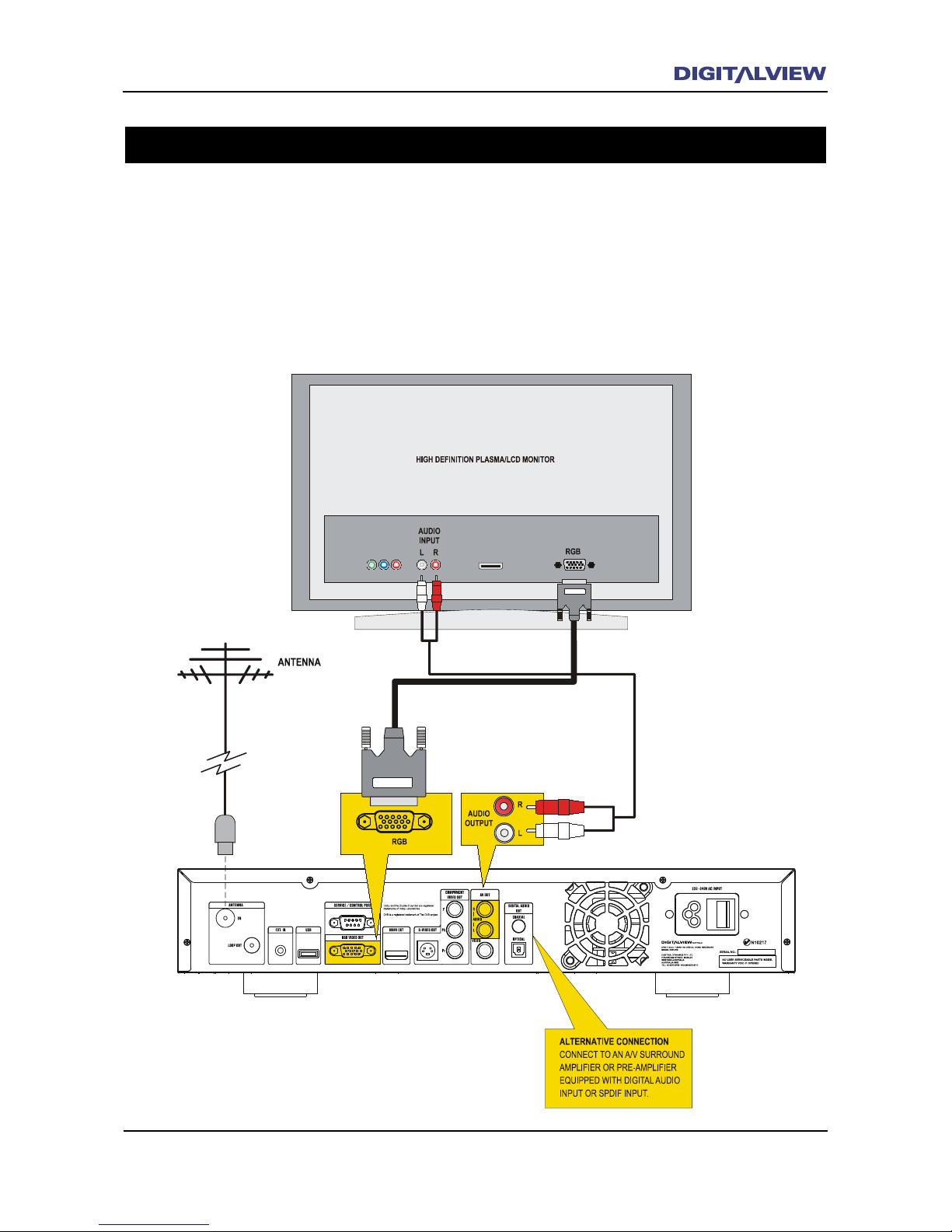
Installation and Setup 19
Connection Diagram - RGB Video (High Denition Analog Video)
Connection using Flat Panel Display with RGB Inputs
Use this type of connection with a high denition analog TV monitor or Flat Panel Display. The
RGB input for some monitors may use ve separate leads for connection. The inputs will usually be
identied as R, G, B, H, and V. If an analog TV monitor is used it must support either 576p, 720p
or 1080i resolutions.
Ensure that power to both the DVR-810 and TV is OFF before any connections are made.
Page 24
20 Installation and Setup
Installation and Setup 21
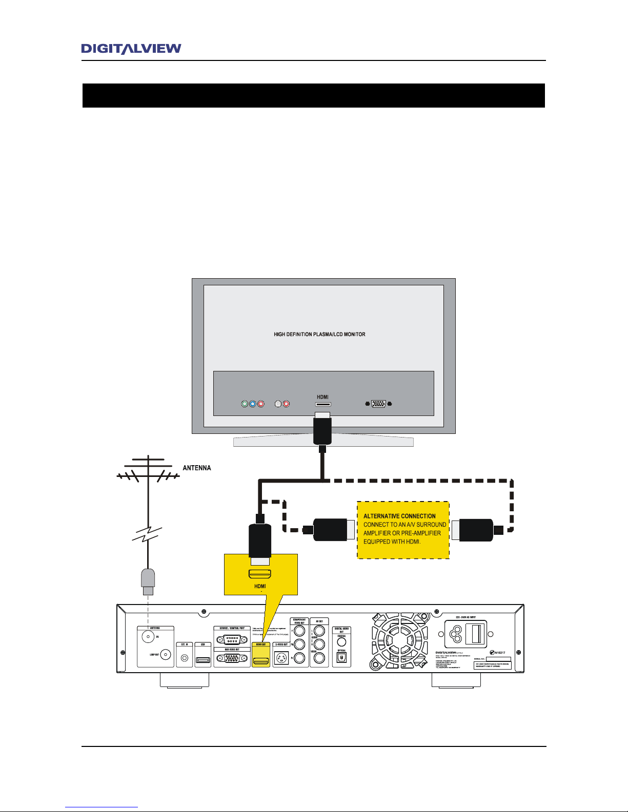
Connection Diagram - HDMI (High Denition Multimedia Interface)
Connection using a High Definition Flat Panel Display with HDMI
HDMI is a digital connection that combines both video and audio in one cable. HDMI is designed
to maximise the picture and sound quality from a Flat Panel Display (plasma or LCD) and/or Home
Theatre System. The results will in most cases be superior picture and sound quality than any
analog video or audio connections.
Ensure that power to both the DVR-810 and TV is OFF before any connections are made.
Page 25
Installation and Setup 21
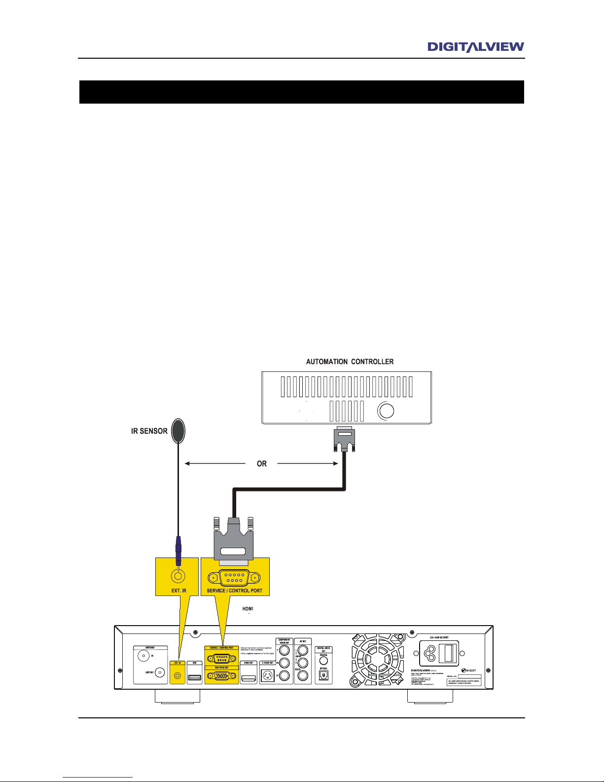
RS232 and Ext IR Connections
Control Automation and External IR Ports
Control Automation refers to specic technologies related to the monitoring and control of any dedicated
appliances or equipment within a home or commercial environment. Each appliance or equipment
being considered for connection to an Automation system, must have the ability to be monitored and
controlled. These types of Automation systems are provided by companies like AMX®, Crestron® and
others.
The DVR-810 provides one RS232 port and one External IR port on the rear panel to meet most
installation requirements.
A bi-directional RS232 serial interface port is used for controlling all functions related to recording,
playback and general Live TV viewing. An ASCII command set for implementation of the Automation
interface is available from Digitalview on request.
Additionally, the DVR-810 provides an External IR port. This port is used when the DVR-810 is located
away from the main viewing area such as in hidden installations. An optional IR sensor, with a 3 metre
lead, can be ordered separately from Digitalview.
Page 26

22 Operational Introduction
Operational Introduction 23
Operational Introduction
Operational Introduction
This Introduction is intended to get you started and using the DVR-810 as quickly as possible. Even with
its advanced functionality, the DVR-810 is very easy to operate and in most cases will not require any
further setup. This section assumes that you have already connected your DVR-810 to your TV monitor
and/or Entertainment System. If not, please refer to the preceding section on “Installation and Setup”
together with any information related to other equipment in your system.
Once you are familiar the basic operation of the DVR-810 and want to explore the extended features,
refer to The MAIN MENU section of this manual.
Using the STBY Button
The STBY (Standby) button is used to switch the DVR-810 into a low power operational mode. If while
recording, or in the event that any scheduled recordings have been set, the DVR-810 will continue to
operate normally. In all cases video and audio outputs are switched OFF.
The following is a ve step Tutorial on how to use your DVR-810. The topics covered include:
1. Tuning The DVR-810 for Digital TV Reception
2. Watching Live TV and Changing Channels
3. Recording Using - On-Demand, Timer, EPG or Timeshifting
4. Playback
5. Transport and Trick Control Modes
Page 27
Operational Introduction 23
Tuning the DVR-810 for Digital TV
Reception
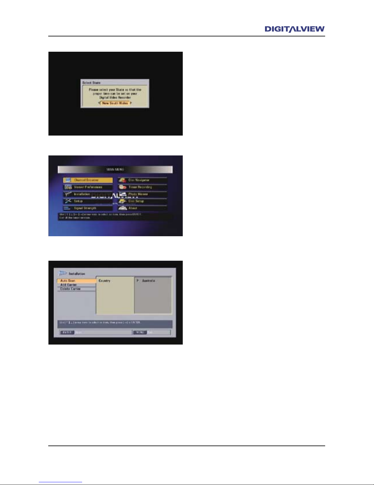
When the DVR-810 is switched On for the rst
time, the start-up screen displays SELECT STATE.
1. Use the Å or Æ buttons on the Remote
Control Unit (RCU) to select the State you live
in.
2. Press the ENTER button on the RCU.
3. The next screen displayed is the MAIN MENU.
4. Using the È button on the RCU select the
INSTALLATION option in the MAIN MENU.
5. Press the ENTER button on the RCU.
6. The next screen displayed is the Installation
dialogue box, with the Auto Scan option
highlighted.
7. Press the ENTER button on the RCU. The DVR810 commences tuning.
After all available digital TV services have been
acquired, the DVR-810 completes the tuning
process and displays one of the TV channels. The
tuning procedure is now complete.
Page 28
24 Operational Introduction
Operational Introduction 25
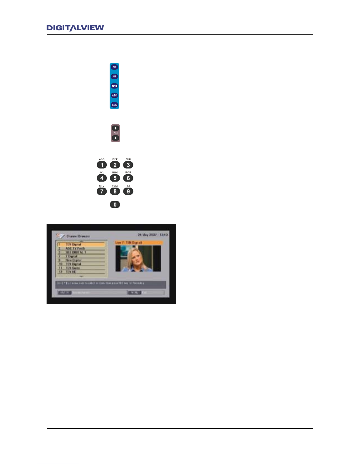
Watching Live TV and Changing Channels
There are three simple ways by which to change
TV channels:
1. Press the BLUE Channel Group buttons on
the RCU. These buttons are identied as
N7,N9,N10,ABC and SBS. Pressing any one
of the Channel Group buttons repeatedly will
select the TV channels/services within that
group.
or
2. Press the CH Ç or È buttons. This will
scroll through all the TV channels/services in
ascending or descending order.
or
3. Press the ENTER button. This will display the
Channel Browser.
Press the Ç or È buttons to select the
required TV channel/service and press
ENTER. A preview window displays the Live
TV program associated with the selected
channel/service. The selected channel/service
is then displayed in full screen mode after a
few seconds.
Page 29
Operational Introduction 25
INFO Function.
To display the current operational status of the
DVR-810 follow these steps:
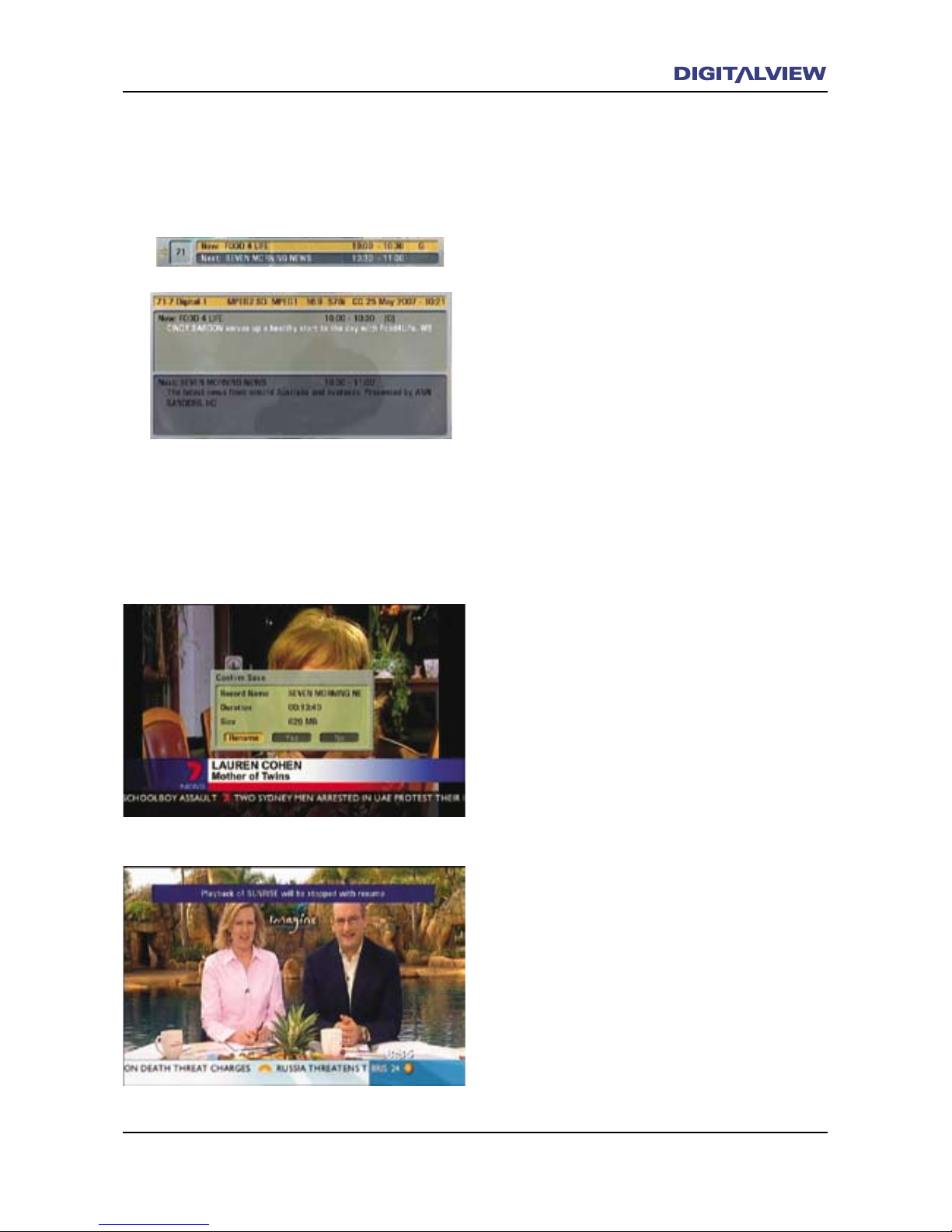
1. Press the INFO button. A dialogue box
displays the appropriate information related
to Live TV viewing, recording and/or playback.
2. If viewing Live TV only, a “summary” dialogue
box at the bottom of the screen will show the
NOW and NEXT EPG program information and
duration.
• Press INFO again. An expanded dialogue box
shows a detailed description of the NOW and
NEXT programs.
• Press the INFO or EXIT button to clear all
dialogue boxes.
Also refer to the section EPG (Electronic
Program Guide)
3. While recording or in playback, the INFO
dialogue box will display information related
to those specic functions.
4. To stop a current recording, press the Ç or È
buttons to select it.
5. Press ENTER.
6. Press the Å or Æ buttons to select the one of
the Save options - Rename, Yes or No.
7. Press ENTER.
8. To stop a current Recorded Title (Playback),
press the Ç or È buttons to select it.
9. Press ENTER. The Recorded Title will resume
from where the title was last stopped.
Page 30
26 Operational Introduction
Operational Introduction 27
EPG (Electronic Program Guide)
For the purpose of this product, EPG is a program
schedule that may or may not be provided by the
broadcaster. The basic mode of EPG is Now and
Next. Now refers to the current program and its
duration. Next refers to the ensuing program.
In most cases the broadcaster will provide
supplementary information on Now / Next
programs, such as detailed program descriptions
and durations.
To further augment the EPG feature, some
broadcaster may provide a full single day or
multiple day program guide. The DVR-810 uses
the information provided in this type of EPG for
scheduled recordings. See, Using the EPG for
Scheduled Recordings.
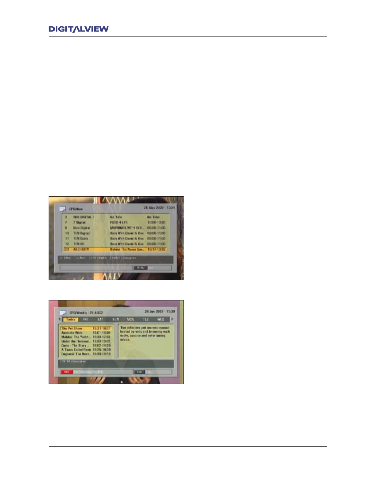
1. While viewing Live TV press the EPG button.
The EPG main dialogue box is shown with
a list of the current TV channels/services
program information.
2. Press the Ç or È button to select the
required TV channel/service.
3. Once the TV channel/service is selected,
press the EPG button, again. The EPG/Weekly
schedule displayed with TODAY highlighted.
Note that some broadcasters may only send
NOW and NEXT information, while others send
single day or multiple day program schedules.
4. Depending on the EPG type (i.e. NOW,
NEXT, single or multiple day) use the Ç or
È buttons to scroll through the available
program titles. On the right side of the
highlighted program title, is a full or partial
description of the program. If a partial
description is displayed, press ENTER to show
the full description. Use the Ç or È buttons
to scroll through the full program description.
5. Press the EPG button to return to the EPG/
Weekly dialogue box, or press the EXIT button
until all dialogue screens are cleared.
Page 31
Operational Introduction 27
Recording Using - On-Demand, Timer, EPG
or Timeshifting
The DVR-810 provides a number of methods to
record a current or any scheduled program/s.
Each method described is specic to the type of
recording required.
Note:
• The functionality of the DVR-810 permits
recording of free-to-air digital TV content
and as such, should only be used as a
temporary means of storage. Please respect
the copyright of the owner/broadcaster and
delete any recorded les after viewing.
To Record a Program On-Demand.
1. Select the required channel/service you want
to record.
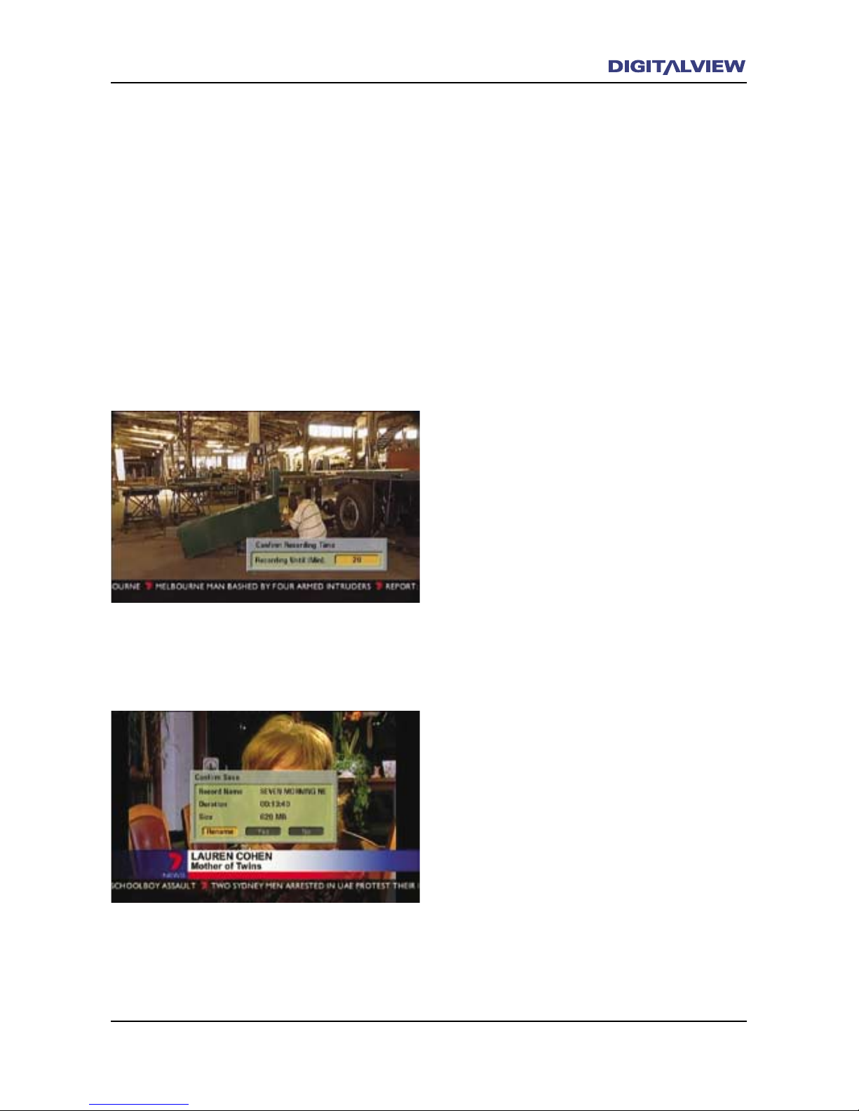
2. Press the REC button on the RCU. A dialogue
box is displayed indicating the remaining
program duration.
3. Press ENTER to accept the value of the
remaining program duration. Alternatively,
press the REC button repeatedly to select one
of the preset values – 30, 60, 90, 180, 360,
480 or user dened. The user-dened value
can be any number from 1 to 480 minutes and
is entered using the numerical keypad on the
RCU.
4. To record a second program follow steps 1 to 3
again.
5. To stop a Recording, Press the <STOP button.
Go to Step 8 if only one program is being
recorded. If two programs are being recorded
a dialogue box is shown with both active
program recordings.
6. Press the Ç or È buttons to select the
recording you wish to stop.
7. Press ENTER
8. Press the Å or Æ buttons to select one of the
Save options - Rename, Yes or No.
9. Press ENTER
Page 32
28 Operational Introduction
Operational Introduction 29
Note:
• While recording, a processing delay of
approximately one second between the realtime Live TV program and actual recording is
normal. In this case the unit is considered
to be in Chase mode. For more information
on Chase mode please refer to the section on
“Chase and Chase Play”.
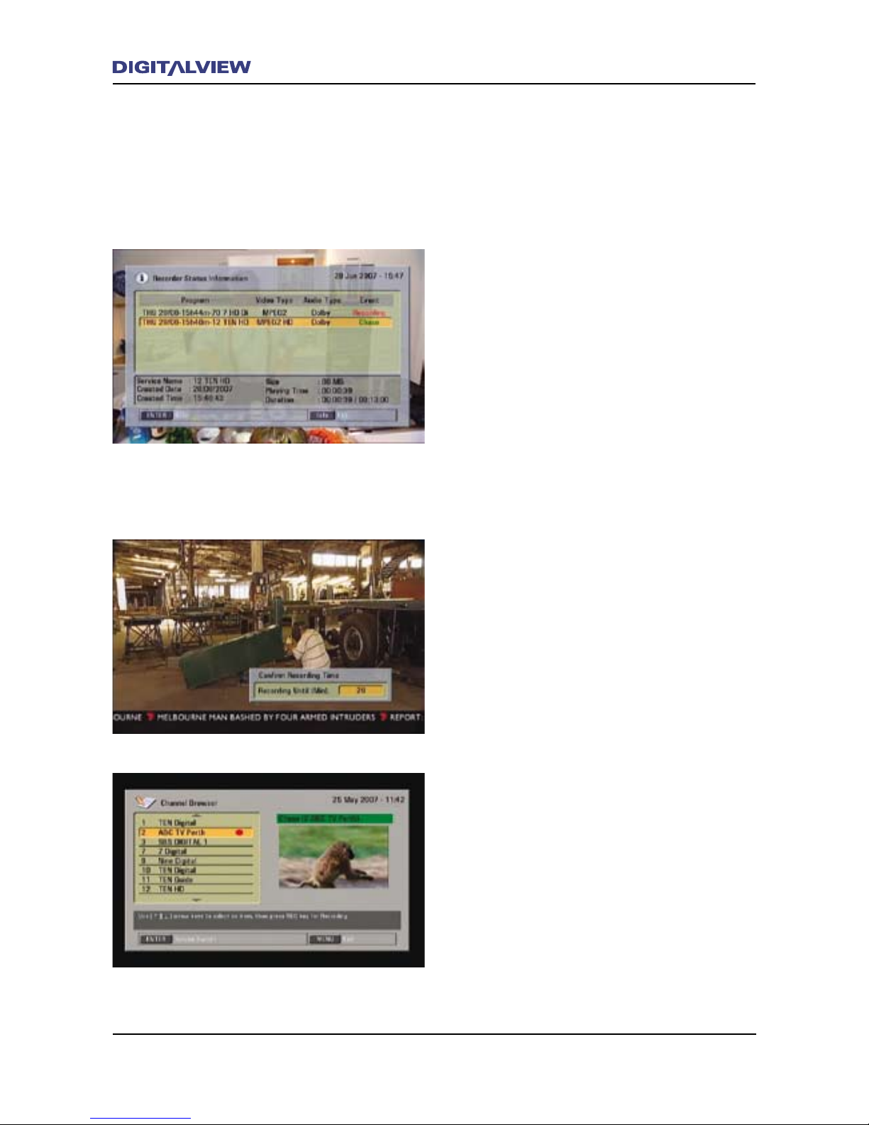
• If you need to know which programs are
being recorded, press the INFO button. Press
EXIT to clear the INFO function.
• To watch one of the programs being recorded,
press the ENTER button. A red icon is shown
next to the program/s being recorded. Select
one of the programs being recorded using the
Ç or È buttons and press ENTER.
• When recording two discrete Channel Groups
(e.g. CH7 and CH9) at the same time, only
those two channels and their associated
services can be selected for viewing. If two
programs are being recorded using only one
discrete Channel Group (e.g. ABC only) then
all Channel Groups can be viewed.
Using the Channel Browser to Record
1. Press ENTER
2. Select a channel/service using the Ç or È
buttons.
3. Press ENTER
4. Press the REC button on the RCU. A dialogue
box is displayed indicating the remaining
program duration.
5. Press ENTER to accept the value of the
remaining program duration. Alternatively,
press the REC button repeatedly to select one
of the preset values – 30, 60, 90, 180, 360,
480 or user dened. The user-dened value
can be any number from 1 to 480 minutes and
is entered using the numerical keypad on the
RCU.
6. To record a second program follow steps 1 to 3
again.
Note:
• If the Channel Browser is accessed during
recording, a red icon is positioned beside the
channel/service being currently recorded.
Page 33
Operational Introduction 29
Recording Programs Using the Schedule Timers.
The unattended recording of programs can be
achieved by using the Schedule Timer functions
provided in the DVR-810. The Timer functions
can be accessed directly by way of the RCU or
by selection from the MAIN MENU. All time
and date information used by the DVR-810 is
referenced to the broadcasters “time stamp”.
There are two types of Discrete Timers that can
be used, these being, EASY TIMER and TIMER REC
(Timer Record).
EASY TIMER allows for single entry Timer
programming, in 15-minute increments, and is
shown as a bar graph.
TIMER REC is used for multiple timer entry and
scheduling (i.e. daily weekly etc.) and can be
programmed in increments of 1 minute.
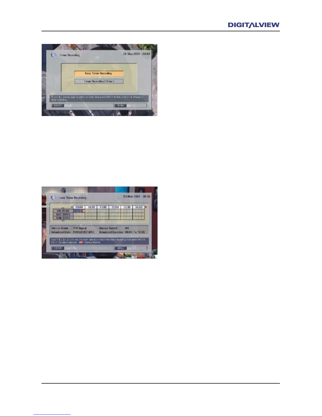
Using the EASY TIMER Function for Scheduled
Recordings
1. Press the EASY TIMER button. The EASY TIMER
main dialogue box is shown.
2. Press the Æ button to move to the Start
Time (in increments of 15 minutes) and press
ENTER.
3. Press the Æ button again to move to the End
Time (in increments of 15 minutes)
4. Press ENTER. A bar-graph shows the total
duration of the scheduled recording time
5. Select YES or NO to conrm the Timer Setup
using the Å or Æ buttons.
6. Press ENTER.
7. To stop a Recording, Press the <STOP button.
8. Press the Å or Æ buttons to select one of the
Save options - Rename, Yes or No.
9. Press ENTER
Note:
• To EXIT the EASY TIMER at any time, press
the EXIT button until the timer dialogue
screens are cleared.
Page 34
30 Operational Introduction
Operational Introduction 31
• The Service Switch is used to view the
scheduled timer program once recording
commences and while watching another
program. If required press the red button to
turn this option On.
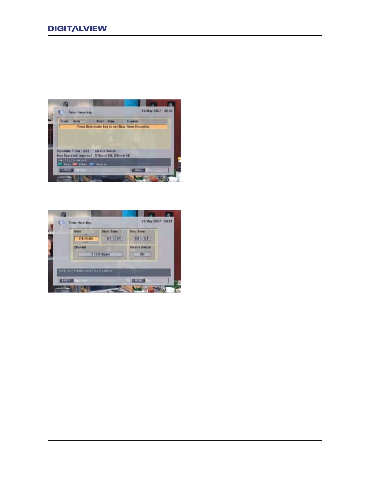
Using the TIMER REC Function for Scheduled
Recordings
1. Press the TIMER REC button. The TIMER REC
main dialogue box is shown.
2. Press the GREEN button on the RCU to start a
new Timer schedule.
3. The Timer Recording dialogue box is
displayed, with the current Date highlighted.
Change the calendar Date if required using the
Ç button. To record a program on a regular
basis, select the “extended” Date options by
pressing the È button. The “extended” Date
options include Everyday, any weekday i.e.
Monday, Tuesday etc., Weekends or Weekly.
4. Press the Æ button to move to the
Start Time. The current time in hours is
highlighted.
5. Press the Ç or È buttons to change the time
in hours.
6. Press the Æ button to move to minutes. The
time in minutes is highlighted.
7. Press the Ç or È buttons to change the time
in minutes.
8. Press the Æ button to move to the Stop
Time.
9. Use the same procedure for the remaining
entries - Stop Time, Channel and Service
Switch.
10. After completing all the entries, Press ENTER.
11. Using the Å or Æ buttons, select YES or NO
to conrm the TIMER REC setup
12. Press ENTER. The TIMER REC entries are now
stored. To EXIT the TIMER REC option at any
time, press the EXIT button until all dialogue
screens are cleared. Any TIMER REC entries
will be cancelled.
Note:
• The calendar Date is only applicable for 30
days in advance of the current date.
Page 35
Operational Introduction 31
• When setting a Timer using the extended
Date option, be aware that the Hard Disc
Drive (HDD) capacity may be exceeded after
multiple Recorded Titles have been stored.
For information of the remaining capacity
on the HDD refer to the MAIN MENU - Disc
Setup - HDD Information menu option.
• The Service Switch option is used to view
the scheduled timer program once recording
commences and while watching another
program.
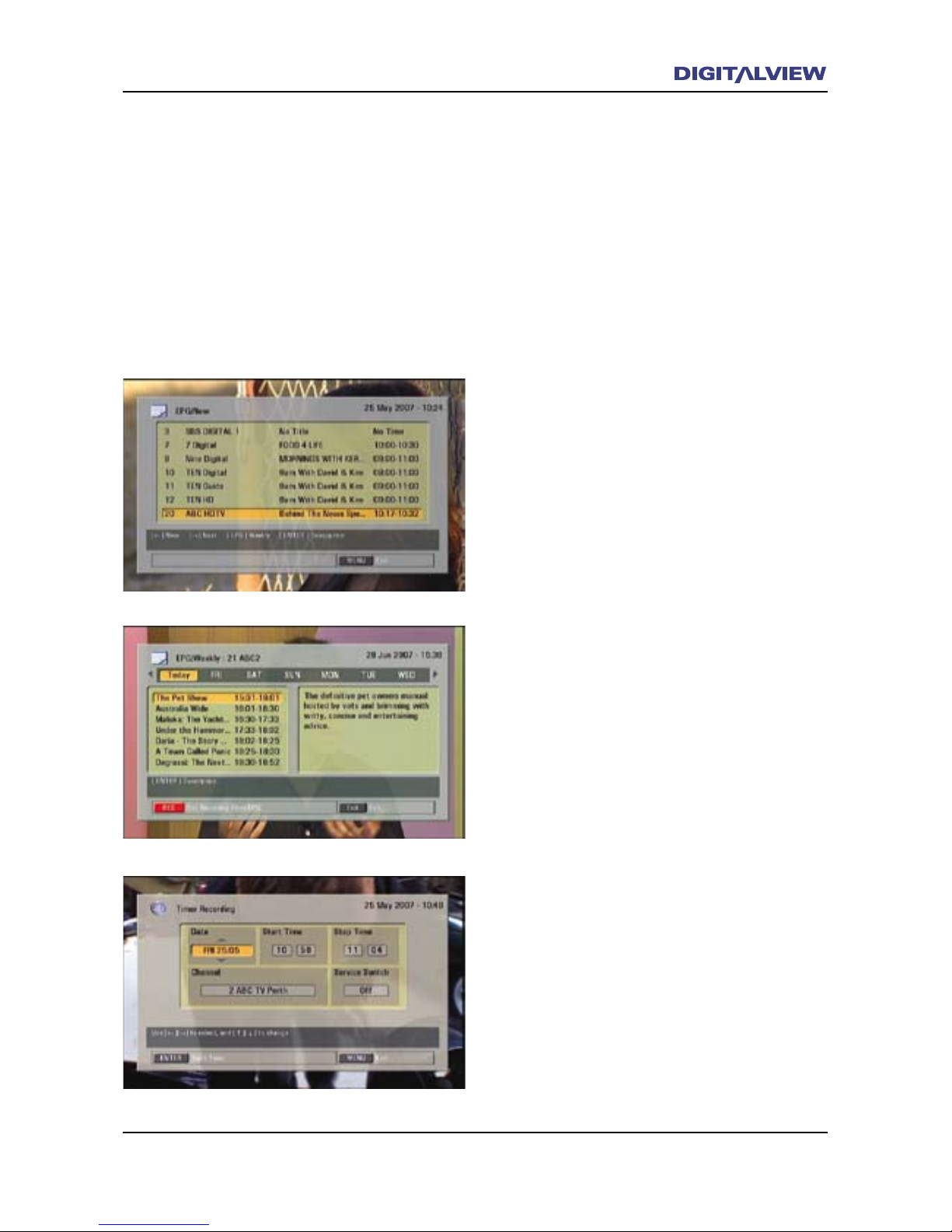
Using the EPG for Scheduled Recordings
1. Press the EPG button. The EPG main dialogue
box is shown.
2. Press the Ç or È button to select the
required TV channel/service.
3. Press the EPG button, again. The EPG main
dialogue box is shown with the currently
selected TV channel/service’s program
schedule.
4. Press the Ç or È buttons to select the
program you wish to schedule for recording.
5. Press the REC button on the RCU. The Timer
Recording dialogue box is displayed, with the
program information.
6. Press ENTER.
7. Press the Å or Æ buttons to select YES or NO
for the scheduled EPG recording.
8. Press ENTER. The EPG Timer entries are now
stored. To EXIT the EPG Timer option at any
time, press the EXIT button until all dialogue
screens are cleared. Any EPG Timer entries
will be cancelled.
Page 36
32 Operational Introduction
Operational Introduction 33
Using Timeshift to Record a Current Program
Timeshifting refers to the on-demand and delayed
viewing of a program that is currently being
watched. This option is activated using the
;PAUSE button.
The Timeshift option would typically be used
where an unexpected interruption in watching
a Live TV program occurs. Once activated,
Timeshift allows the user to resume watching
the program from the time it was paused to the
current time.
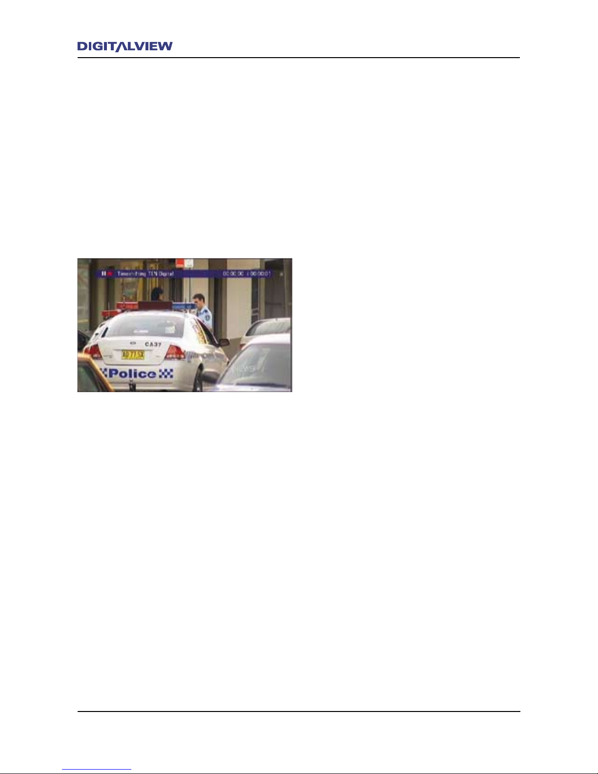
Recording with Timeshift
1. While watching Live TV, press the;PAUSE
button. The Live TV video and audio stop
and a single video frame is displayed. This is
normal and indicates that the Timeshift mode
is active.
2. When required, press the4PLAY button to
resume watching “Timeshifted Live TV”.
3. To stop Timeshift, Press the <STOP button.
4. Press the Å or Æ buttons to select the one of
the Save options - Rename, Yes or No.
5. Press ENTER.
6. To stop a Recording, Press the <STOP button.
7. Press the Å or Æ buttons to select one of the
Save options - Rename, Yes or No.
8. Press ENTER.
Page 37
Operational Introduction 33
Playback
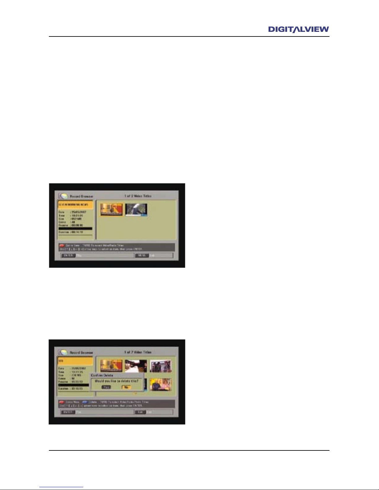
Any Recorded Title can be played by selecting
it from the Record Browser. Titles are shown
as “thumbnail” pictures for each Recorded Title.
All titles are sorted in the Record Browser by
date and time, i.e. the most current recording is
highlighted when the Record Browser is opened.
The REC LIST Button
Pressing the REC LIST button. displays the
Record Browser dialogue box. This is where all
Recorded Titles are selected for playback. The
Record Browser also allows single Recorded
Titles to be deleted.
Playback a Recorded Title
1. Press the REC LIST button on the RCU. The
Record Browser dialogue box is displayed
showing all Recorded Titles.
2. Press the Å, Æ, Ç or È buttons on the RCU
to select one of the Recorded Titles.
3. Press ENTER. The selected title commences
playback in full screen mode.
4. To pause playback press the ;PAUSE button.
5. To continue playback press the 4PLAY button
6. To Stop playback, press the <STOP button.
Live TV now resumes.
Note:
• While in playback and if the <STOP button
is pressed, playback will always resume from
where the title was last stopped.
Deleting a Single Recorded Title Using the
Record Browser.
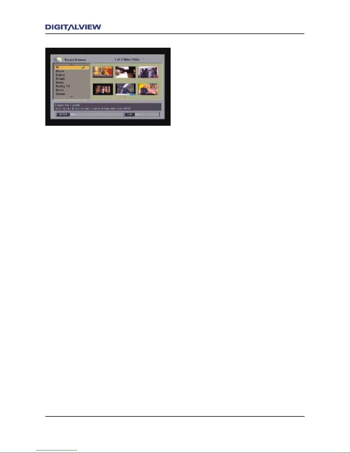
1. Press the REC LIST button on the RCU. The
Record Browser dialogue box is displayed
showing all Recorded Titles.
2. Press the Å, Æ, Ç or È buttons on the RCU
to select one of the Recorded Titles.
3. Press the BLUE button. A conrmation
dialogue box is displayed.
4. Conrm Delete by selecting Yes.
Page 38
34 Operational Introduction
Operational Introduction 35
Playback a Recorded Title Using Genre
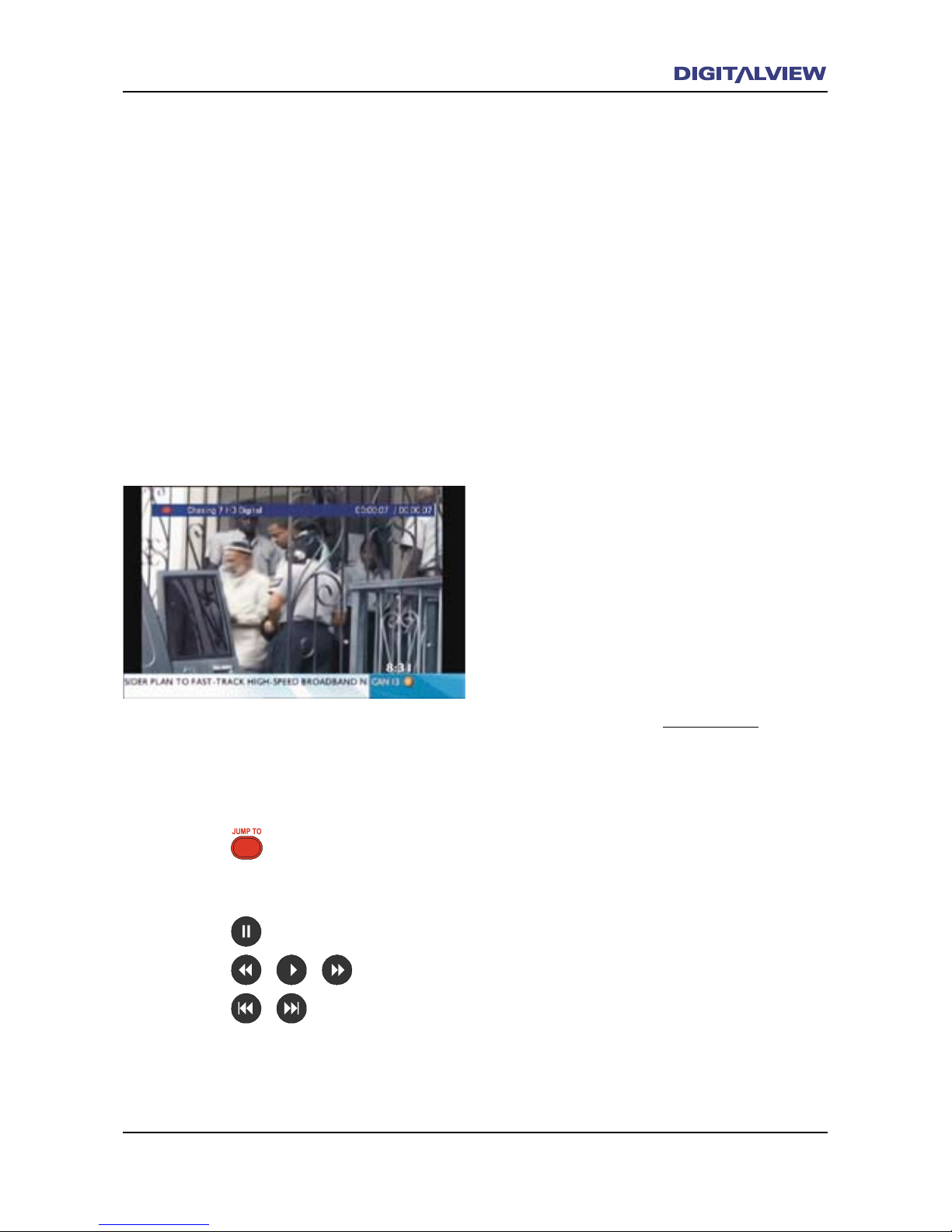
1. Press the REC LIST button on the RCU. The
Record Browser dialogue box is displayed
showing all Recorded Titles.
2. Press the red button on the RCU. A dialogue
box showing the Genre classications is
displayed.
3. Select the Genre classication you wish to
choose from, using the Ç or È buttons.
4. Press ENTER
5. Press the Å, Æ, Ç or È buttons on the RCU
to select one of the Recorded Titles.
6. Press ENTER. The selected title commences
playback in full screen mode.
7. To pause playback press the ;PAUSE button.
8. To continue playback press the 4PLAY button
9. To stop playback, press the <STOP button.
Live TV now resumes.
For information on setting the Genre type, refer
to the section on Genre.
Page 39
Operational Introduction 35
Transport and Trick Control Modes.
The DVR-810 has the same basic recording and
playback functions of a standard Video Tape
Recorder but with a much greater level of user
control. For the purpose of this specic product
there are two modes of control. These are:
1. The Transport Controls
2. Trick Mode Controls
Essentially both the Transport and Trick Control
Modes are identical in operation. The Transport
Controls are used when the DVR-810 is in
Playback. The Trick Control Modes are used when
recording.
Chase and Chase Play
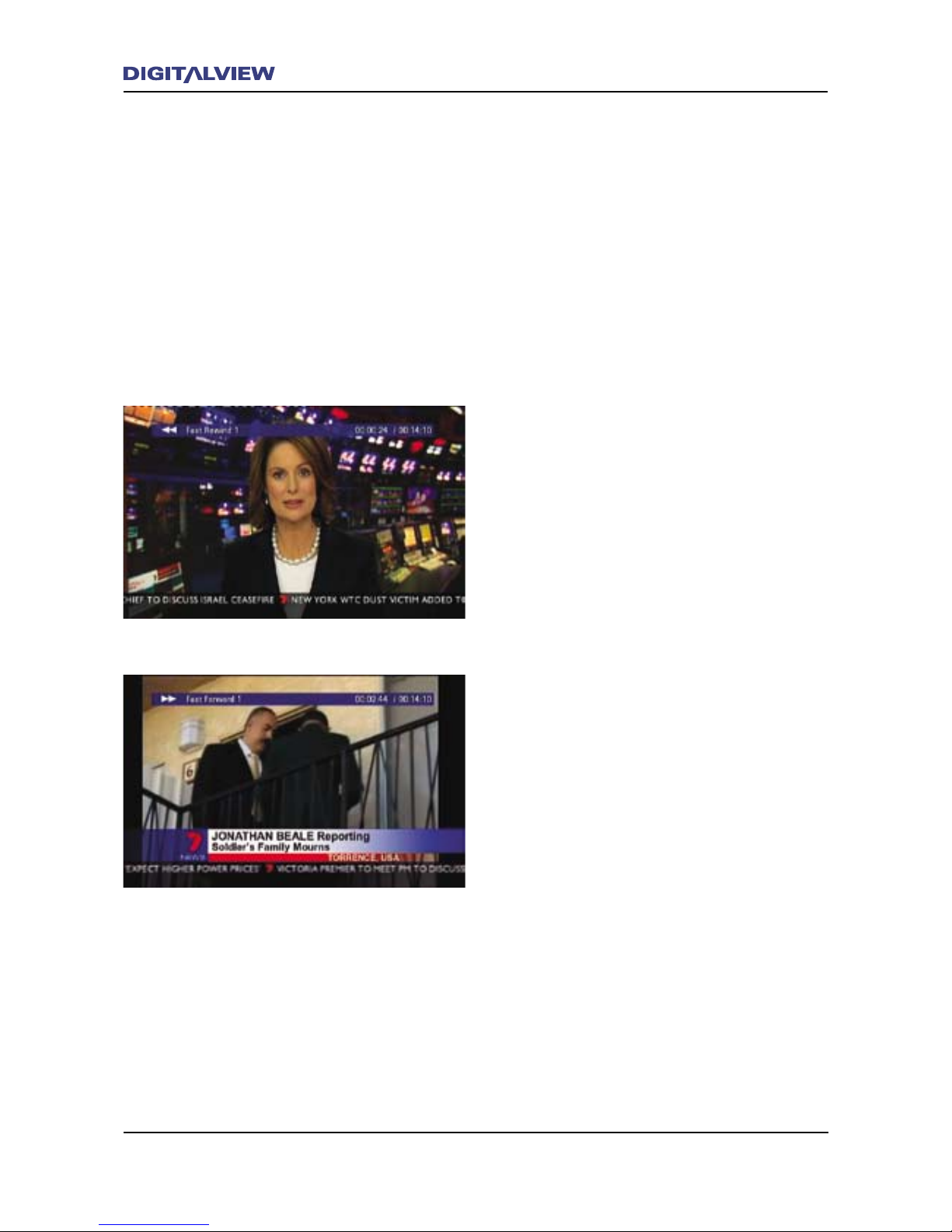
When a Trick Mode is used during recording,
the relationship between the actual real-time
recording and the time position being watched
is delayed, and is referred to as Chase or Chase
Play. Simply put, Chase only occurs when a Trick
Mode is activated and the program being watched
is delayed with reference to the real-time Live TV
recording position.
Note:
• Chase or Chase Play does not apply to the
Playback mode of operation.
Operation of the Trick and Transport Control
Modes
The following operational steps will describe how
to use the Trick Mode controls during recording.
The same instructions apply to the Transport
Mode controls during Playback.
Due to the nature of how the video is recorded
While recording, Trick Modes can be used, for
example to, rewind to a specic time in the
program currently being recorded. The Trick Mode
controls supported by the DVR-810 include:
1. 7FAST REWIND
2. 8FAST FORWARD
3. ;PAUSE
Page 40
36 Operational Introduction
Operational Introduction 37
4. 9REVERSE SKIP
5. :FORWARD SKIP
6. JUMP
7. Variable Speed, Bi-directional Slow Motion
Viewing -;PAUSE + 7FAST REWIND or
;PAUSE +8FAST FORWARD
8. Frame by Frame - ;PAUSE repeated.
Use these simple steps to operate the Trick Mode
controls while recording. When pressing the Trick
Mode controls, a status bar at the top of the
screen shows any information related to that
function.
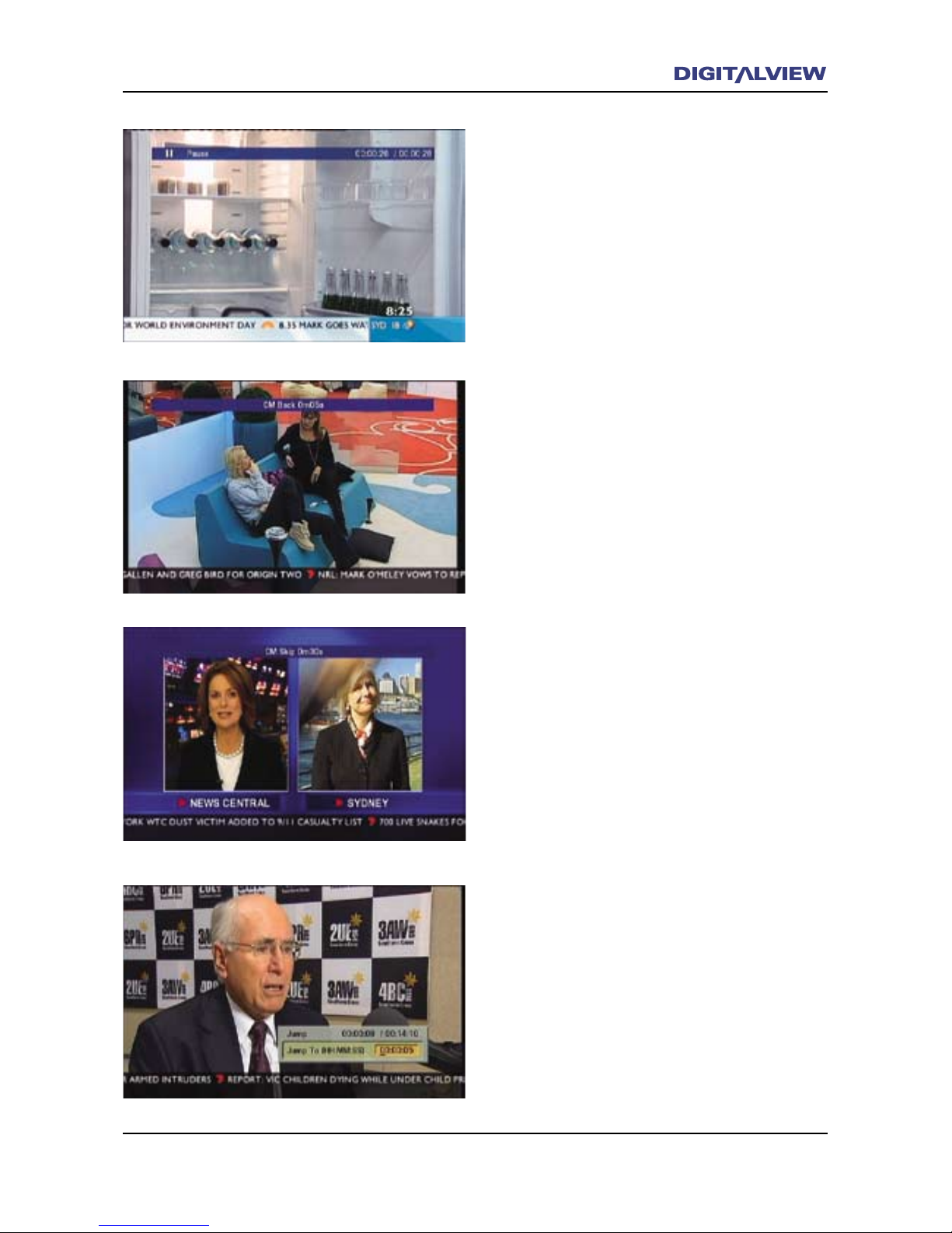
1. Press the 7(FAST REWIND) button. Each
press after that will rewind the current
position in increments of x2, x3, x4 and x5
normal speed.
2. Press the 8 (FAST FORWARD) button. Each
press after that will move the current position
forward in increments of x2, x3, x4 and x5
normal speed.
Note:
• 8FAST FORWARD is only possible if 7FAST
REWIND had previously been activated.
• When pressing either the 7FAST REWIND or
8FAST FORWARD button, a status bar at the
top of the screen indicates the number of
times that button has been pressed. Refer to
following relationship between the number of
button presses and actual speed.
x1= x2 normal speed,
x2= x4 normal speed,
x3= x8 normal speed,
x4= x16 normal speed,
x5= x32 normal speed,
Page 41
Operational Introduction 37
3. While recording, press the ;PAUSE button to
temporarily suspend real-time viewing of the
recording. A single video frame is displayed.
Press the4PLAY button to resume viewing.
The recording is now in the Chase mode.
6. JUMP TO allows you to move to any absolute
time within the duration of the recording and
keep viewing from that point on-wards.
• Press the JUMP TO (red) button. A dialogue
box is displayed with a value indicating the
elapsed time of the recording. Enter an
absolute time value in Hr, Min, Sec. using the
numerical keypad on the RCU. The program
being recorded will Jump to the that value. If
the value entered is greater current duration
of the recording, no Jump will take place.
5. While recording, press the :FORWARD SKIP
button to move the current recording 5-sec
forward. :FORWARD SKIP can only be applied
if the recording is at least thirty seconds
behind the real-time recording position. Each
press after that will move the current Chase
position forward in increments of 30sec.,
1min., 2min., 3min., 5min., and Title End.
4. While recording, press the 9REVERSE SKIP
button to move the current recording position
5-sec backwards. The recording is now being
viewed in Chase mode. Each press after that
will move the Chase position backward in
increments of 5sec., 15sec., 30sec., 1min.,
2min and Title Start
Page 42
38 Operational Introduction
Operational Introduction 39
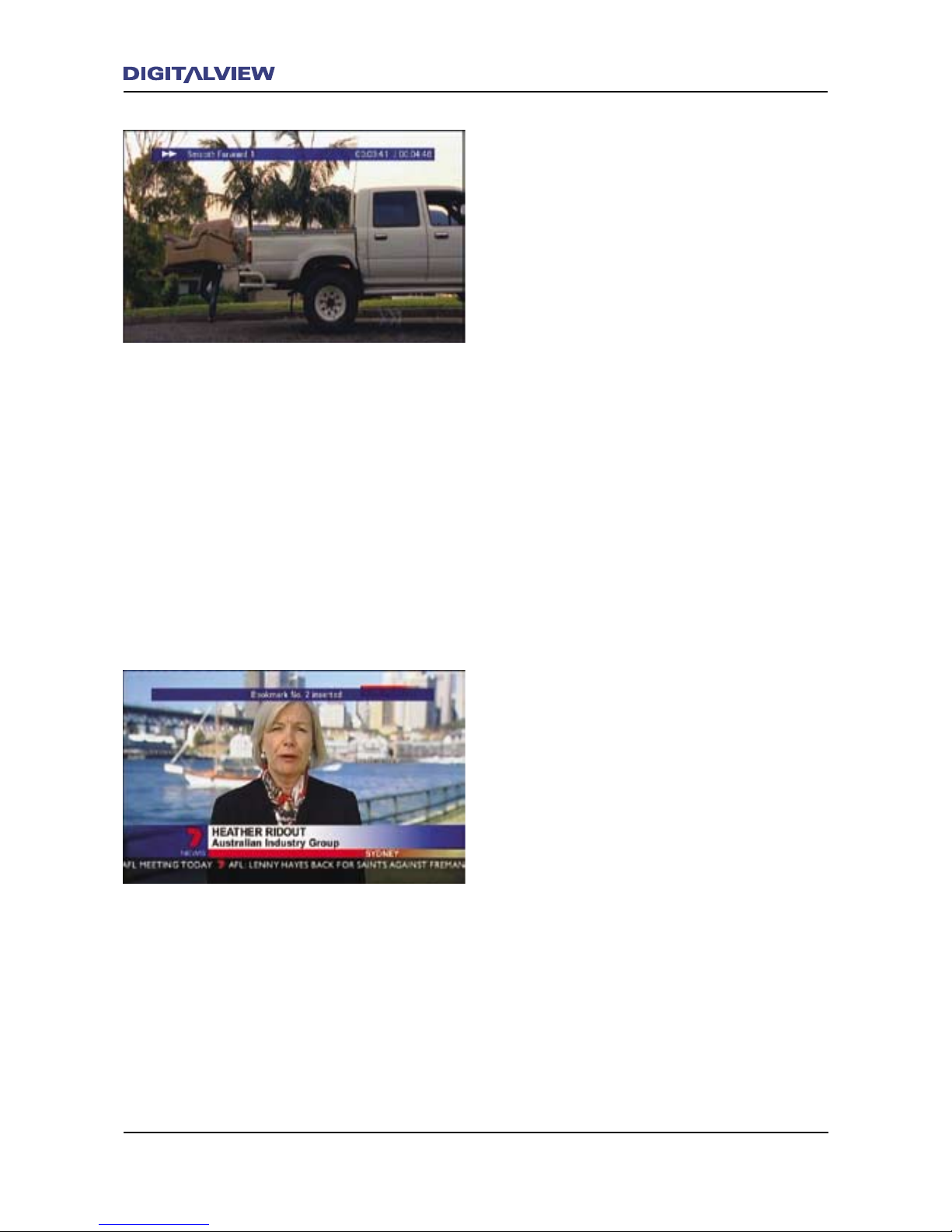
7. VARIABLE SPEED, BI-DIRECTIONAL SLOW
MOTION VIEWING – Any current recording can
be viewed in forward or reverse Slow Motion.
Three incremental speeds are available for
each direction.
• Press;PAUSE. . The Live TV video and audio
stop and a single video frame is displayed.
• Press either the 7FAST REWIND button for
Reverse Slow motion or 8FAST FORWARD for
Forward Slow Motion. To increase the speed
of motion press the appropriate button again
and up to three times.
• Press the 4PLAY button to return to normal
viewing.
8. FRAME-BY-FRAME VIEWING – Any current
recording can be viewed Frame-by-Frame in
forward motion.
• Press;PAUSE. . The Live TV video and audio
stop and a single video frame is displayed.
• Press ;PAUSE repeatedly to move forward
frame-by-frame.
• Press the 4PLAY button to return to normal
viewing.
Bookmarking During Recording or Playback
A Bookmark is a means of inserting reference
points within a Program Title that can be recalled
later. When a Bookmark is recalled, playback
continues from the selected Bookmark.
1. While recording or in playback, press the
BOOKMARK button. Up to eight Bookmarks
for each Program Title is allowed. All
Bookmarks are saved with the Recorded Title.
2. To recall a Bookmark while recording, press
the Å or Æ buttons.
3. To view a previous Recorded Title with
Bookmarks, press the REC LIST button and
select the required title to play.
4. To recall a Bookmark during playback, press
the Å or Æ buttons.
Note:
• To edit or delete Bookmarks from a Recorded
Title refer to the Disc Navigator option in
the MAIN MENU.
Page 43
Operational Introduction 39
Supplementary Operations.
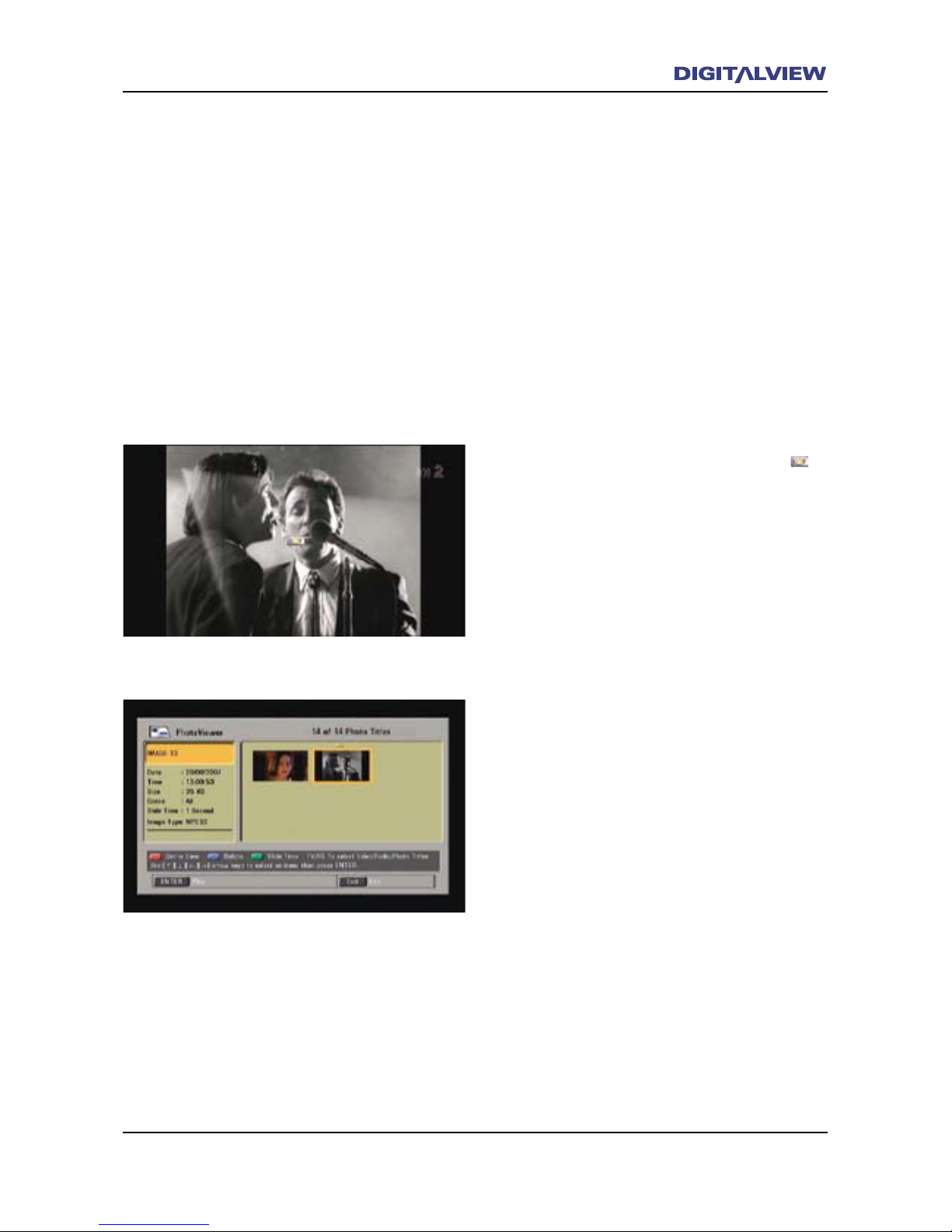
Photo Capture and Playback
An added feature included with the DVR-810 is
the screen capture of single video frames for
playback at a later time. This feature is referred
to as Photo Capture. Photo Capture can be
invoked while watching Live TV, Recording or
Playback. All Photos are located in a single le
and are not categorized. Playback of Photos is
viewed as a slideshow with a preset viewing time.
All Photos play in sequence after the selected
“start” Photo.
While watching Live TV or during Recording or
Playback:
1. Press the GREEN button. A “camera icon”
is displayed indicating that the video frame
has been captured and stored.
2. To playback the captured video frames
(Photos), rst select Photo Viewer from the
MAIN MENU and press ENTER. To view the
Photos in order of the most recently captured,
rst select Sort – Created Time option in the
Disc Navigator MAIN MENU. Refer to the
section, Sort.
3. A dialogue box showing “thumbnail” pictures
of the Photos is displayed.
4. Select a Photo from where to start, using
Å or Æ buttons and press ENTER. Playback
commences from the selected picture and
continues until all subsequent pictures are
displayed. If the Slide Time period is set for
an extended time the Å or Æ buttons can be
used to manually navigate to any Photo.
5. To extend the viewing time that each Photo is
displayed, increase the Slide Time period in
the Photo Viewer setup dialogue box.
For more information on how to customize the
Photo Viewer - Slide Time period, refer to the
section Conguring the Photo Viewer.
Page 44

40 Operational Introduction
Operational Introduction 41
PIP (picture-In-Picture)
PIP is when a small preview screen is displayed
within the main screen, allowing the viewer to
watch two programs (Live TV and/or Recorded
Title) simultaneously. Only the main screen
program audio is heard. The PIP program can
be viewed in the main screen by “Swapping”.
Swapping changes the current PIP program to the
main screen and the main screen program to the
PIP screen.
Note:
• The PIP function is cannot be enabled while
recording.
• PIP will be disabled if the REC button is
pressed.
Using PIP with Live TV
1. While watching a Live TV program press the
YELLOW ON/OFF button. The PIP preview
window is displayed showing the Live TV
program in both the main screen and the PIP.
2. To change the Live TV program in the PIP
press the YELLOW CH+ or CH- buttons.
3. To change the program being viewed in the
PIP to the main screen, press the SWAP
button.
4. To turn the PIP Off, press the YELLOW ON/OFF
button.
Using PIP with Live TV and a Recorded Title
1. While watching a Live TV program press the
YELLOW ON/OFF button. The PIP preview
screen is displayed.
2. To change from the Live TV program in the PIP
to a Recorded Title, press the YELLOW LIVE/
LAST WATCHED REC button. The rst Recorded
Title starts to play in the PIP. A green
arrow indicates that the PIP is previewing a
Recorded Title.
3. To change the Recorded Title being viewed in
the PIP press the YELLOW CH+ or CH- buttons.
4. To change the Recorded Title viewed in the
PIP to the main screen, press the SWAP
button.
5. To turn the PIP Off, press the YELLOW ON/OFF
button.
Page 45
Operational Introduction 41
CC/TT (Closed Captions/Teletext)
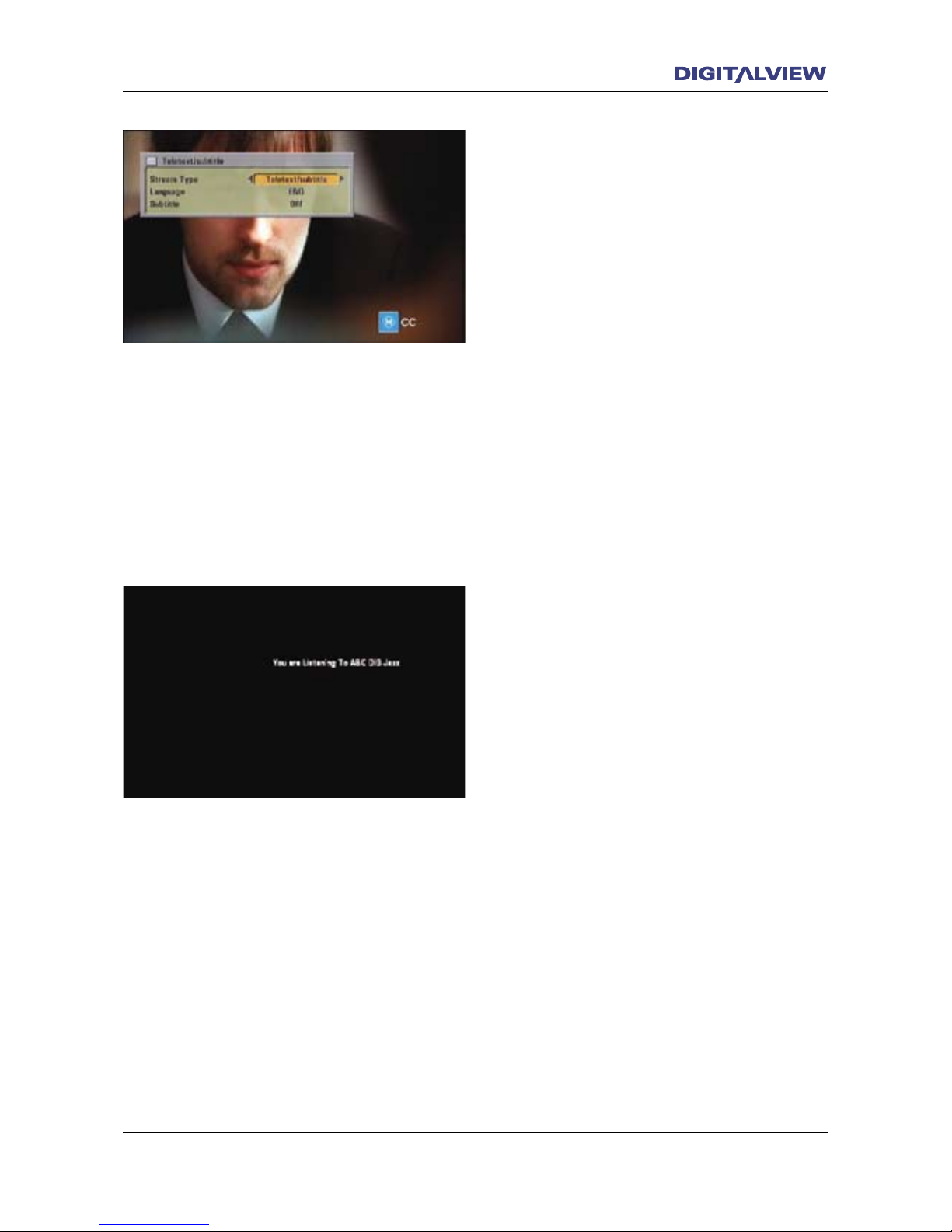
1. The CC/TT option is used to display Closed
Captions or Teletext pages.
2. Press the CC/TT button to display the
Teletext/Subtitle dialogue box. The Stream
Type – Teletext/Subtitle is highlighted.
3. Select Teletext/Subtitle to display Closed
Captions. If required press the Æ button
on the Remote Control Unit (RCU) to select
Teletext/Magazine to display Teletext pages.
4. Press the È button to select Subtitle.
5. Press the Æ button to select On.
6. Press the EXIT button to clear any menus and
return to normal viewing. Closed Captions or
Teletext is now enabled.
Note:
• To disable Closed Captions or Teletext follow
the above procedure and select Off in the
Subtitle dialogue box.
RD/TV
1. Pressing the RD/TV button selects between
Television or Radio services. Not all
broadcasters transmit Radio content together
with Television.
2. Press the RD/TV button. The rst available
radio service is displayed.
3. Press the CH Ç or È buttons to change to
the next radio service.
4. If required, press the RD/TV button to return
to the television services.
Page 46
42 The Main Menu
The Main Menu 43
The MAIN MENU
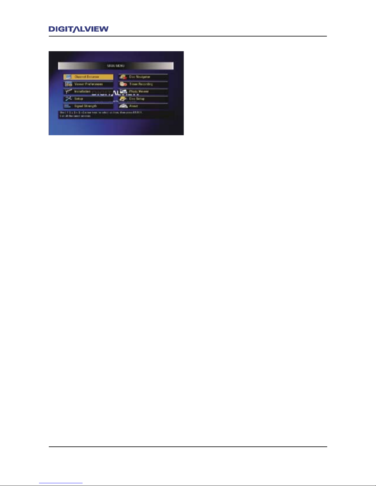
The MAIN MENU options for the DVR-810 is
used for the setup and customizing of specic
functions related to its operation. In most cases
the MAIN MENU does not need to be accessed.
All operational control is by way of the Remote
Control Unit.
The MENU Button
When pressed, the MENU button displays all the
Menu Options related to the operation and setup
of the DVR-810.
The following sections describe each of the MAIN
MENU options.
Page 47
The Main Menu 43
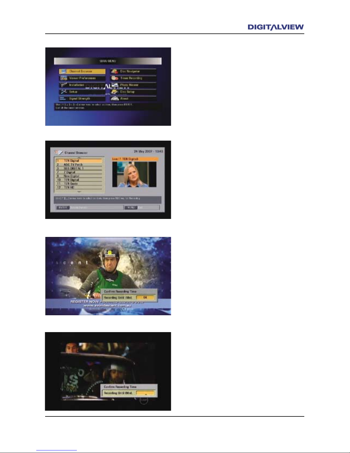
The Channel Browser.
The Channel Browser displays a list and Program
Preview Window of all digital TV and Radio
channels/services available after the initial
tuning of the DVR-810. The Channel Browser
can be used to select and/or record any selected
channel/service.
Viewing
1. Select the Channel Browser from the MAIN
MENU or press the ENTER button.
2. Press the Ç or È buttons to select the
required TV channel/service and press
ENTER. A preview window displays the Live
TV program associated with the selected
channel/service. The selected channel/service
is then displayed in full screen mode after a
few seconds.
Recording
1. Select the Channel Browser from the MAIN
MENU or press the ENTER button.
2. Press the Ç or È buttons to select the
required TV channel/service and press ENTER.
3. Press the REC button on the RCU. A dialogue
box is displayed indicating the remaining
program duration.
4. Press ENTER to accept the value of the
remaining program duration. Alternatively,
press the REC button repeatedly to select one
of the preset values – 30, 60, 90, 180, 360,
480 or user dened. The user-dened value
can be any number from 1 to 480 minutes and
is entered using the numerical keypad on the
RCU.
5. Press the EXIT button to clear any menus and
return to normal viewing.
Page 48
44 The Main Menu
The Main Menu 45
Viewer Preferences
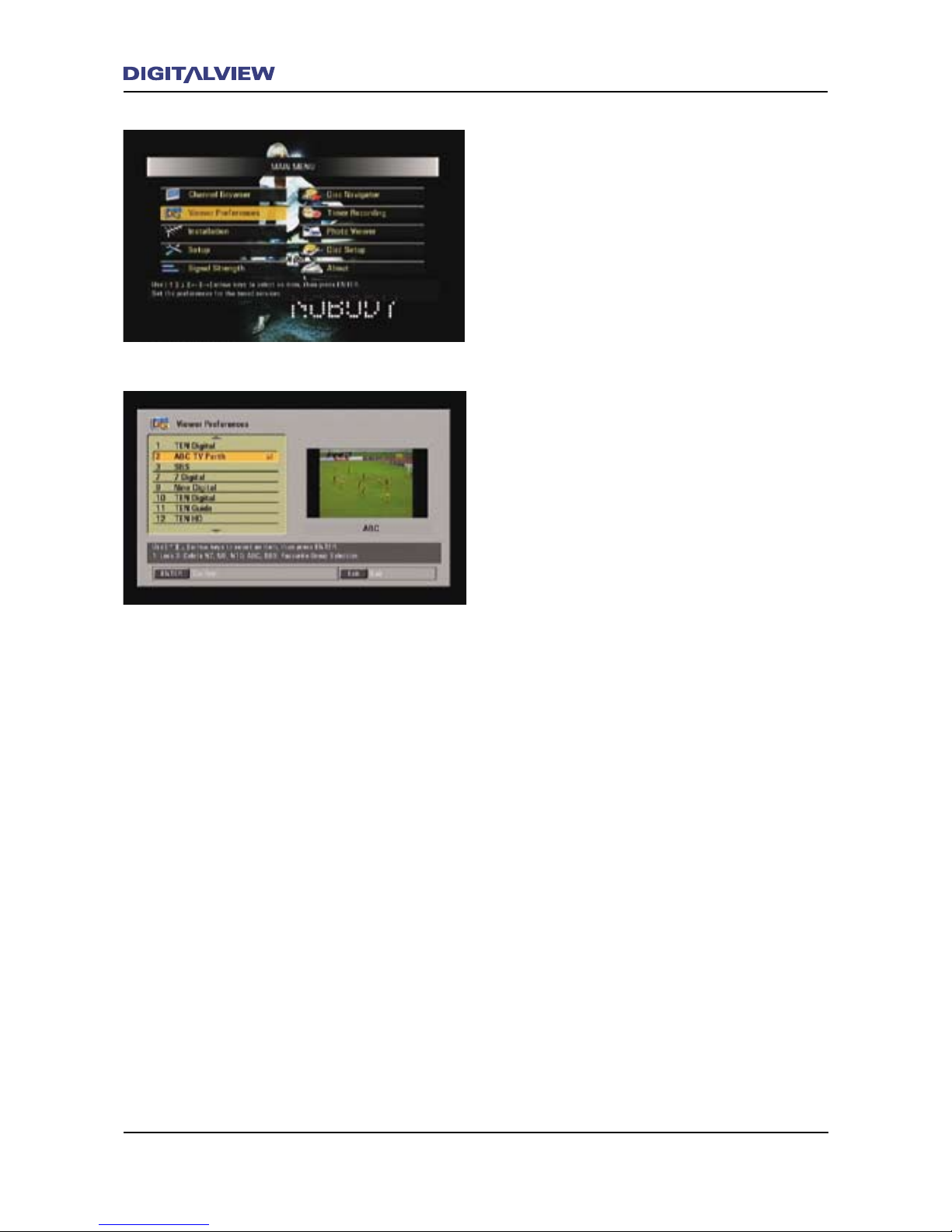
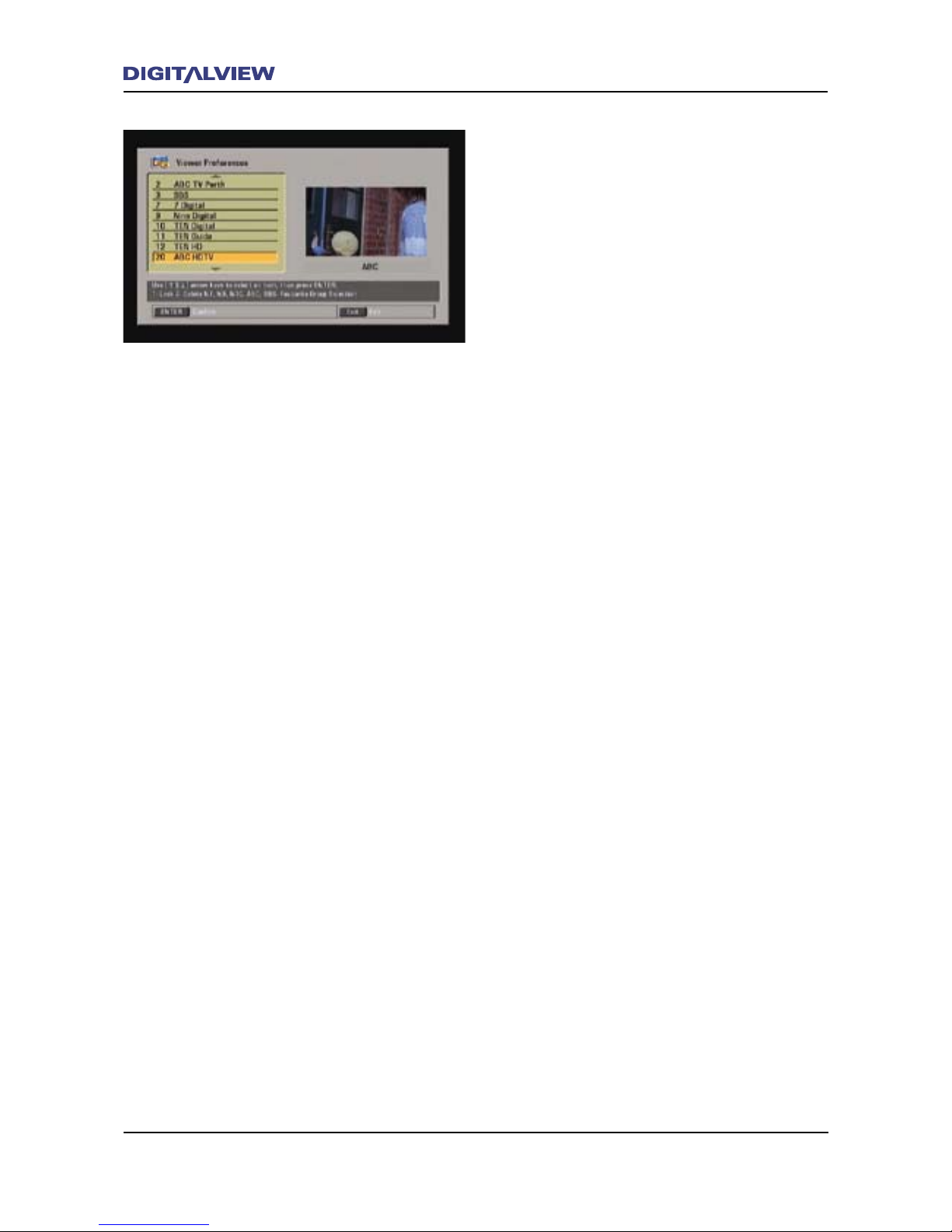
Allows Locking, Deleting and Channel Group Reassignment of any individual TV channel/service.
Lock a Channel/Service –
Locking prevents viewing of a specic TV
channel/service. A four digit password is
required to allow further access to the locked
service/channel.
1. Select Viewer Preferences from the MAIN
MENU and press ENTER.
2. Select the TV channel/service that requires
locking using the Ç or È buttons.
3. Press u on the numerical keypad. Ï is shown
beside the channel/service. If required and to
deselect lock, press u again
4. Press ENTER. The TV channel/service is now
locked from viewing.
5. Press the EXIT button to clear any menus and
return to normal viewing.
To Unlock a Channel/Service –
1. Select Viewer Preferences from the MAIN
MENU and press ENTER.
2. Select the channel/service to unlock using
the Ç or È buttons. Ï is shown beside the
locked channel/service.
3. Press u on the numerical keypad and
press ENTER. The password dialogue box is
displayed.
4. Enter the correct password and press ENTER.
The default password is 0000 and is only
applicable if this password has not been
changed. The TV channel/service is now
unlocked and allows normal viewing access.
5. Press the EXIT button to clear any menus and
return to normal viewing.
Page 49
The Main Menu 45
Viewing a Locked Channel/Service –
1. While viewing Live TV, select the locked
channel/service. A Password dialogue box is
displayed.
2. Enter the password using the numerical
keypad. The default password is 0000 and is
only applicable if this password has not been
changed.
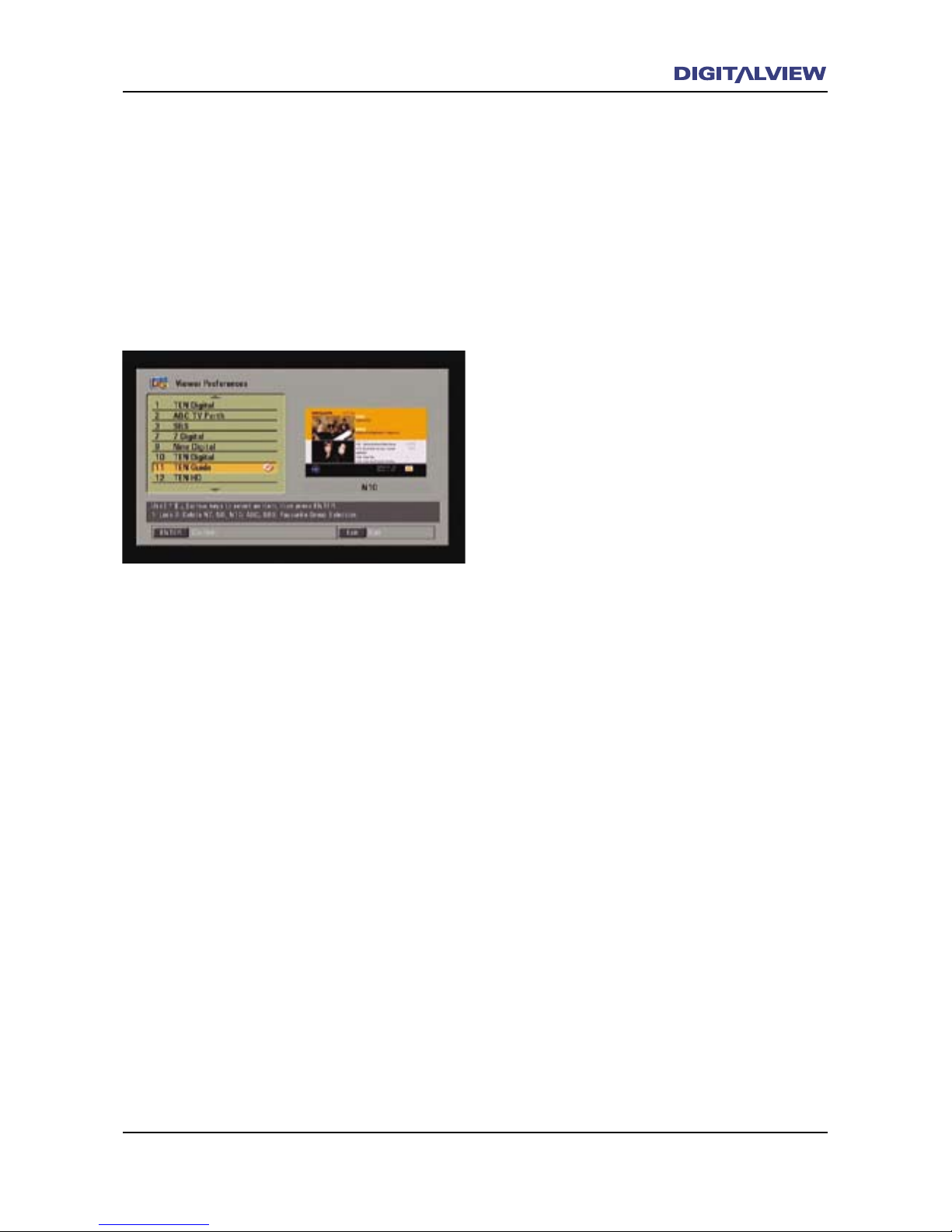
Delete a Channel/Service
Deleting allows the removal of an individual TV
channel/service.
1. Select Viewer Preferences from the MAIN
MENU and press ENTER.
2. Select the TV channel/service to delete using
the Ç or È buttons.
3. Press v on the numerical keypad. V is
shown beside the channel/service. If required
and to deselect lock, press v again
4. Press ENTER. A conrmation dialogue box is
displayed.
5. Conrm the delete option by selecting Yes.
6. The specied TV channel/service is deleted.
7. Press the EXIT button to clear any menus and
return to normal viewing.
Note:
• To restore the deleted service refer to the
section on Installation > Add Carrier.
Reassigning the Channel Group Buttons (BLUE
Buttons)
Channel Groups allows for fast access to changing
channels/services. Channel Group Re-assignment
allows the BLUE Channel Group button to be
re-assigned to a different broadcaster if required.
This option is sometimes used in rural or country
regions where the local broadcaster may not
be associated with one of the primary national
broadcasters.
Page 50
46 The Main Menu
The Main Menu 47
1. Select Viewer Preferences from the MAIN
MENU and press ENTER.
2. Select the TV channel/service to reassign
using the Ç or È buttons. The button
assigned to the channel/service is shown
below the preview window.
3. Press the BLUE button according to the
assignment show below the preview window.
This will remove the existing Channel Group
assignment from the selected channel/service.
4. Now, press any one of the other BLUE buttons
to assign a new Channel Group to the selected
channel/service. This button is now the new/
re-assigned Channel Group button. Usually
the reassignment of the channel/service has
some association with one of the national
broadcasters.
5. Press the EXIT button to clear any menus and
return to normal viewing.
If required repeat Step 1-4 for other TV channels/
services.
Page 51
The Main Menu 47
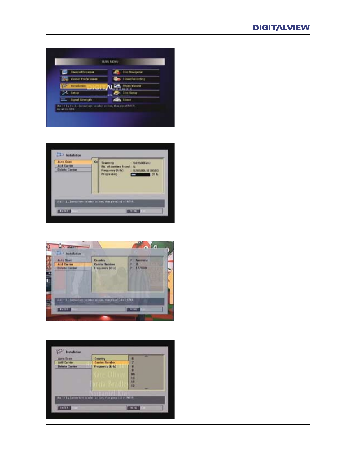
Installation
Used for the overall or selective tuning and
management of digital TV services.
Installation - Auto Scan
Use this option for tuning or re-tuning all Freeto-Air TV channels/services.
1. Select Installation from the MAIN MENU
and press ENTER. The Auto Scan option is
highlighted.
2. Press ENTER. Tuning commences until all
channels/services are established.
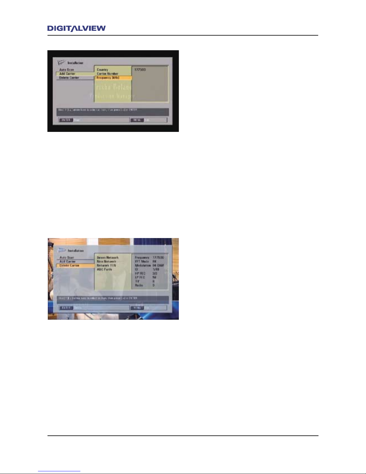
Installation - Add Carrier
Use this option to tune to any specic
broadcaster or Free-to-Air TV service provider.
It is recommended that only service personnel
access this option.
1. Select Installation from the MAIN MENU and
press ENTER.
2. Select Add Carrier using the Ç or È buttons.
3. Press ENTER or the Æ button. Country,
Australia is selected.
4. Select and highlight Carrier Number using
the Ç or È buttons.
5. Press ENTER or the Æ button. A “channel” list
is displayed with “channel” 6 selected. Note:
This list is the “Digital TV Channel Assignment
List” and is not related to the actual channel/
service itself.
6. Select a “channel” for tuning using the Ç or
È buttons press ENTER. The tuning dialogue
box is displayed showing the progress of
operation. When complete, the unit displays
the new service.
7. The broadcaster or Free-to-Air TV service
provider is added to the Channel Browser list.
8. Press the EXIT button to clear any menus and
return to normal viewing.
Page 52
48 The Main Menu
The Main Menu 49
Frequency
As an alternative to Add Carrier, use the
Frequency option to tune to any specic
broadcaster or Free-to-Air TV service provider.
It is recommended that only service personnel
access this option.
1. Select Installation from the MAIN MENU and
press ENTER.
2. Select Add Carrier using the Ç or È buttons
and press ENTER.
3. Select and highlight Frequency using the Ç
or È buttons.
4. Press ENTER or the Æ button. A dialogue box
with the frequency 177500 is highlighted.
5. Using the numeric keypad enter the required
six digit frequency in kHz. The tuning
dialogue box is displayed showing the
progress of operation. When complete, the
unit displays the new service.
6. Press the EXIT button to clear any menus and
return to normal viewing.
Installation - Delete Carrier
This option deletes a broadcaster from the
Channel Browser list.
1. Select Installation from the MAIN MENU and
press ENTER.
2. Select Delete Carrier using the Ç or È
buttons and press ENTER.
3. Select Frequency using the Ç or È buttons.
4. Select the broadcaster to delete using the Ç
or È buttons and press ENTER.
8. Conrm the delete option by selecting Yes.
9. All channels/services are deleted for the
specied broadcaster.
10. Press the EXIT button to clear any menus and
return to normal viewing.
Note:
• To restore the deleted service refer to the
section on Installation > Add Carrier.
Page 53
The Main Menu 49
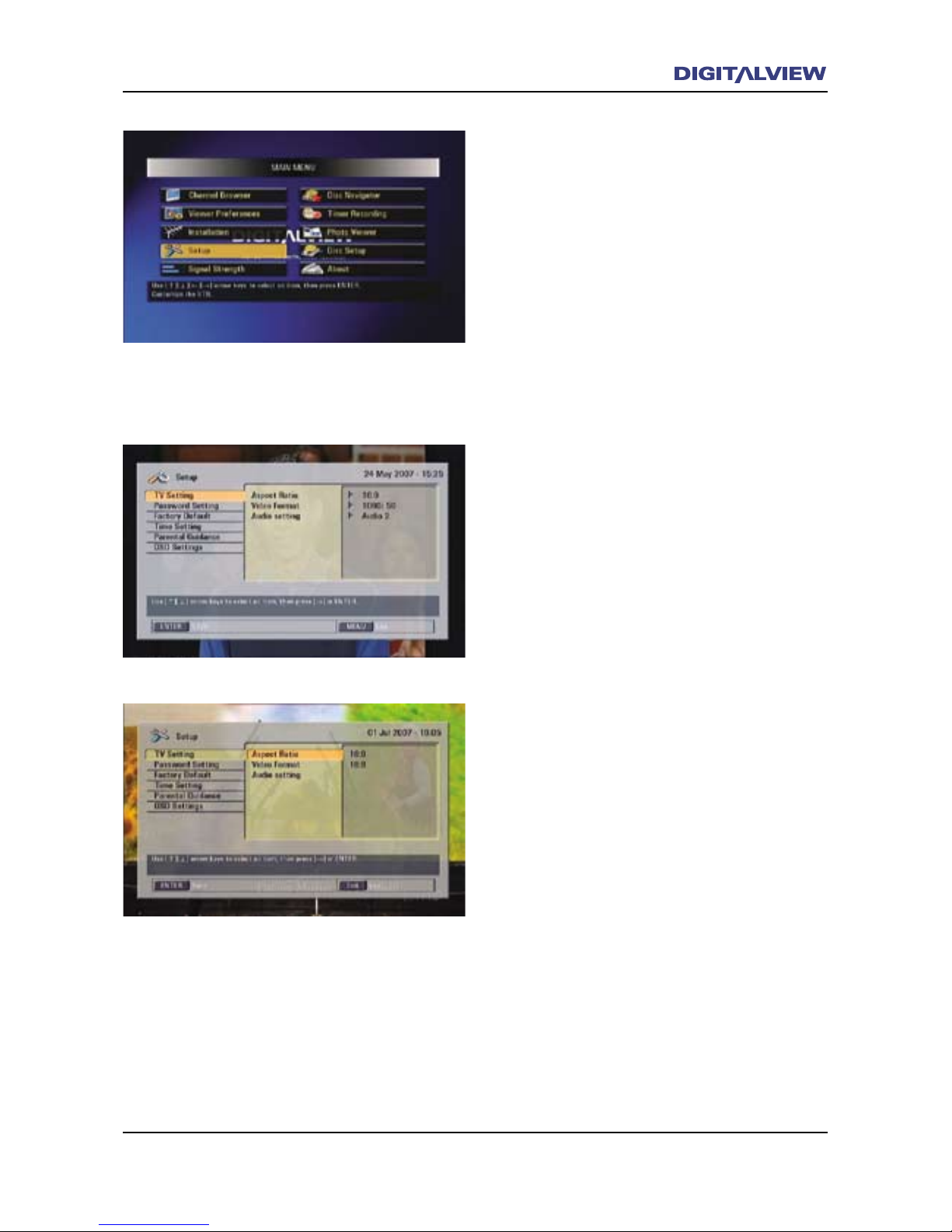
Setup
Setup allows you customize the functional
operation associated with the DVR-810.
TV Settings
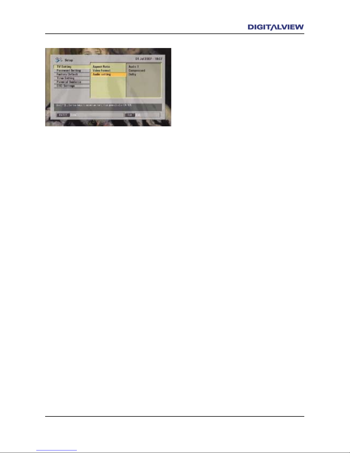
This option allows specic video and audio
conguration settings to be changed.
TV Settings - Aspect Ratio
The Aspect Ratio settings allow you to congure
the DVR-810 to independently adjust the display
format for widescreen (16:9) and normal screen
(4:3) TV’s/Monitors.
1. Select Setup from the MAIN MENU and press
ENTER.
2. Select TV Settings using the Ç or È buttons.
3. Press ENTER or the Æ button. Aspect Ratio is
selected.
4. Press ENTER or the Æ button. The Set option
is displayed.
5. Press ENTER.
6. The option (High Denition) HD Aspect Ratio
(16:9) is highlighted. This is the default
selection if you are using the HDMI, YPbPr
(Component) or RGB video outputs with a
widescreen TV/Monitor.
7. If required use the Å or Æ buttons to change
the HD Aspect Ratio. The picture changes
while each of the three aspect ratio options is
selected.
8. Press ENTER to change to the new HD Aspect
Ratio.
9. To change the (Standard Denition) SD
Aspect Ratio use the È button to select it
and press ENTER.
10. The SD Aspect Ratio (16:9) is highlighted.
This is the default selection if you are using
the Composite Video and/or S-Video, outputs
with a widescreen TV/Monitor.
Page 54
50 The Main Menu
The Main Menu 51
11. Use the Å or Æ buttons to change the HD
Aspect Ratio. The picture changes while each
of the three aspect ratio options is selected.
12. Press ENTER to change to the new SD Aspect
Ratio.
13. Press the EXIT button to clear any menus and
return to normal viewing.
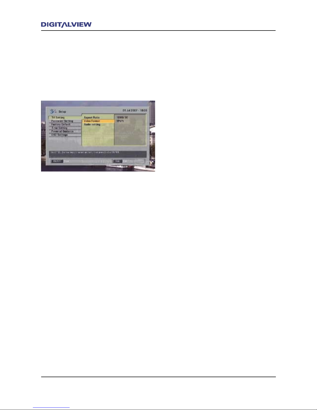
TV Settings – Video Format
The Video Format settings allow you to change
the video resolution and video connection that
may be required by your TV/Monitor. The factory
default video resolution is set to 1080i. The video
connection type is YPbPr (Component Video).
Note:
• If Native is selected in Video Format,
the program video will be output at the
resolution that is determined by that
specic broadcaster. In this case the TV/
Monitor that is used must support all video
resolutions, i.e. 576I, 576p, 720p and 1080i.
If you need to change the default video
resolution or video connection type:
1. Select Setup from the MAIN MENU and press
ENTER.
2. Select TV Settings using the Ç or È buttons.
3. Select Video Format using the Æ and È
buttons and press ENTER. The Set option is
highlighted.
4. Press ENTER. The Video Format of 576p 50 is
highlighted.
5. Press the Å or Æ buttons to select the video
resolution required and press ENTER.
6. To change the video connection type select
Analog Output. Analog Output is highlighted.
7. Press the Å or Æ buttons to select the type
of video connection required and press ENTER.
8. Press the EXIT button to clear any menus and
return to normal viewing.
Page 55
The Main Menu 51
TV Settings – Audio Setting
The DVR-810 allows viewing, recording and
playback using the audio formats of AC3
and MPEG1. The broadcaster determines the
audio format transmitted. In some cases the
broadcaster will transmit both AC3 Dolby Digital
and MPEG1. This is indicated in the Audio
dialogue box as Audio 1 and Audio 2. At other
times, the audio may be transmitted as MPEG1
or AC3 only. In this case the Audio dialogue box
shows only Audio 1.
Note:
• Audio Setting only needs to be changed
if the attached equipment (AV receiver) is
not capable, or may be having problems
decoding AC3 Dolby Digital. When the DVR810 is connected to an AV receiver using the
optical or coaxial digital audio output, the
“Uncompressed” setting should be selected.
1. While viewing a current channel/service
press the INFO button twice. A dialogue box
showing detailed information about the NOW/
NEXT programs is displayed.
2. At the top of dialogue box details referring
to the channel/service, video, audio and
other related information is displayed. If the
audio type is Dolby proceed to next step. If
the audio type is MPEG1 nd an appropriate
channel/service with Dolby.
3. Select Setup from the MAIN MENU and press
ENTER.
4. Select TV Settings using the Ç or È buttons
and press ENTER.
5. Select Audio Setting using the È button. A
description of the audio being received by
the DVR-810 is displayed in the information
section on the right. Only proceed with the
next step if the audio information shows
Dolby
6. Press ENTER. The Set option is displayed.
7. Press ENTER. Three audio categories are
shown. Audio, SPDIF Output and Audio
Type.
8. Audio is highlighted and shows Audio1 or
Audio 2.
Page 56
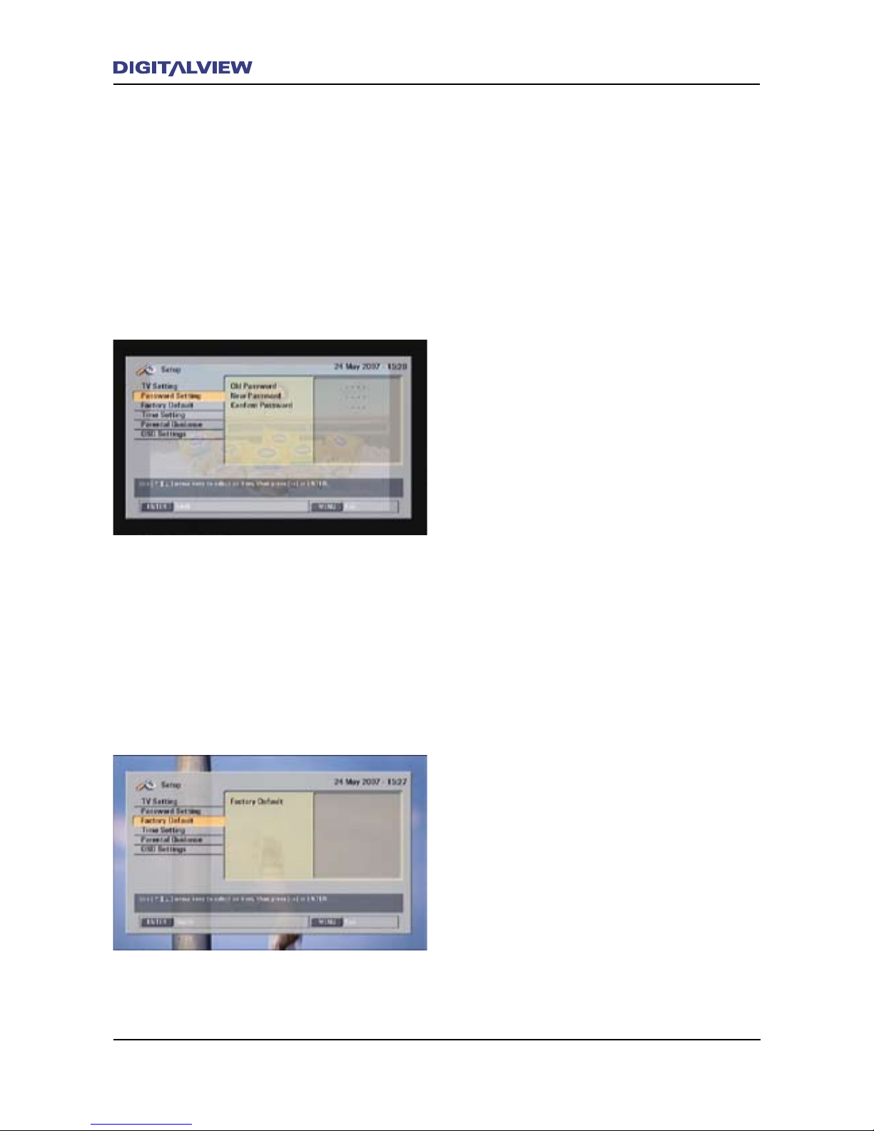
52 The Main Menu
The Main Menu 53
9. Press the Å or Æ buttons to select the
audio stream with Dolby. Dolby is shown in
Audio Type. The SPDIF Output will show
Compressed.
10. Select SPDIF Output using the È button.
11. Press the Å or Æ buttons to select
Uncompressed.
12. Press ENTER.
13. Press the EXIT button to clear any menus and
return to normal viewing.
Password Setting
The DVR-810 uses a password to restrict access
to certain functions, if required. The default
password is 0000. If required the default
password can be changed using the Password
Setting option.
1. Select Setup from the MAIN MENU and press
ENTER.
2. Select Password Settings using the Ç or È
buttons and press ENTER.
3. Old Password is highlighted. Enter the digits
0000.
4. New Password is highlighted. Enter a new
four digit number.
5. Conrm Password is highlighted. Enter the
same new four digit number.
6. The new password is now active.
7. Press the EXIT button to clear any menus and
return to normal viewing.
Factory Default
Factory Default resets all the conguration
settings for the DVR-810 to the original values.
This option should only be used if an operational
problem with the DVR-810 is encountered.
1. Select Setup from the MAIN MENU and press
ENTER.
2. Select Factory Default using the Ç or È
buttons and press ENTER.
3. Enter your password. If the password has not
been changed from its original setting enter
0000.
Page 57
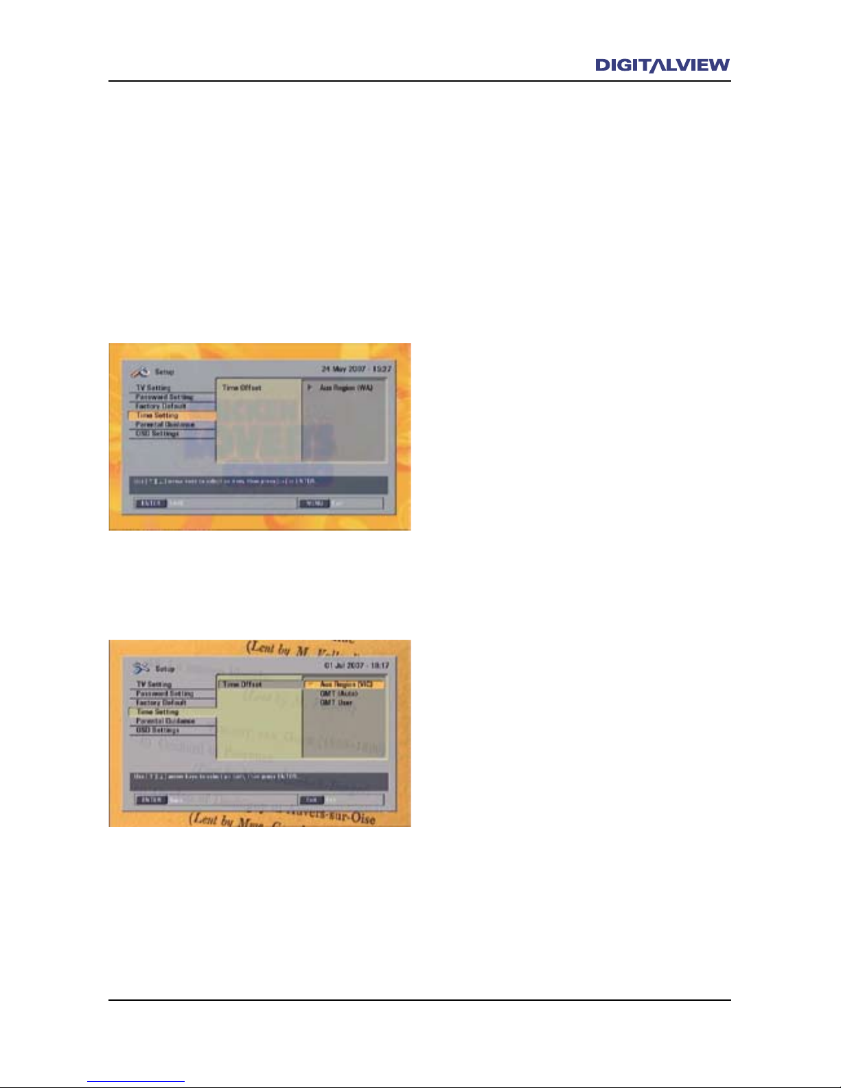
The Main Menu 53
4. Press ENTER. Set is highlighted.
5. Press ENTER
6. Press the Å or Æ buttons and select Yes to
conrm the Factory Default option and press
ENTER.
Note:
• After applying the Factory Default option,
the DVR-810 will need to be re-tuned. Refer
to the section Tuning the DVR-810 for
Digital TV Reception.
Time Setting
Generally, all broadcasters in each State sends
the correct GMT referenced time and date
information with the program and therefore no
adjustment off this Menu item is necessary.
Time Setting allows the State and GMT User
options to be modied if required. The GMT User
option allows the GMT + daylight saving offset to
be specied. The GMT (Auto) option should be
selected for normal operation.
1. Select Setup from the MAIN MENU and press
ENTER.
2. Select Time Setting using the Ç or È
buttons and press ENTER. Time Offset is
highlighted.
3. Press ENTER. The Aus Region option is
highlighted. Sometimes Aus Region may not
be selected. To select it, use the Ç or È
buttons and press ENTER
4. Press ENTER. State is highlighted.
5. Select the State you live in using the Å or Æ
buttons and then press ENTER.
6. Select GMT User using the Ç or È buttons
and press ENTER. GMT Offset is highlighted.
7. Adjust the GMT Offset (GMT + daylight
saving offset) using the Å or Æ buttons to
the required value and then press ENTER. As
a general rule the maximum offset for any
Australian State will be +2 or –2 of GMT.
8. GMT User is now used as the local time
reference.
9. Press the EXIT button to clear any menus and
return to normal viewing.
Page 58
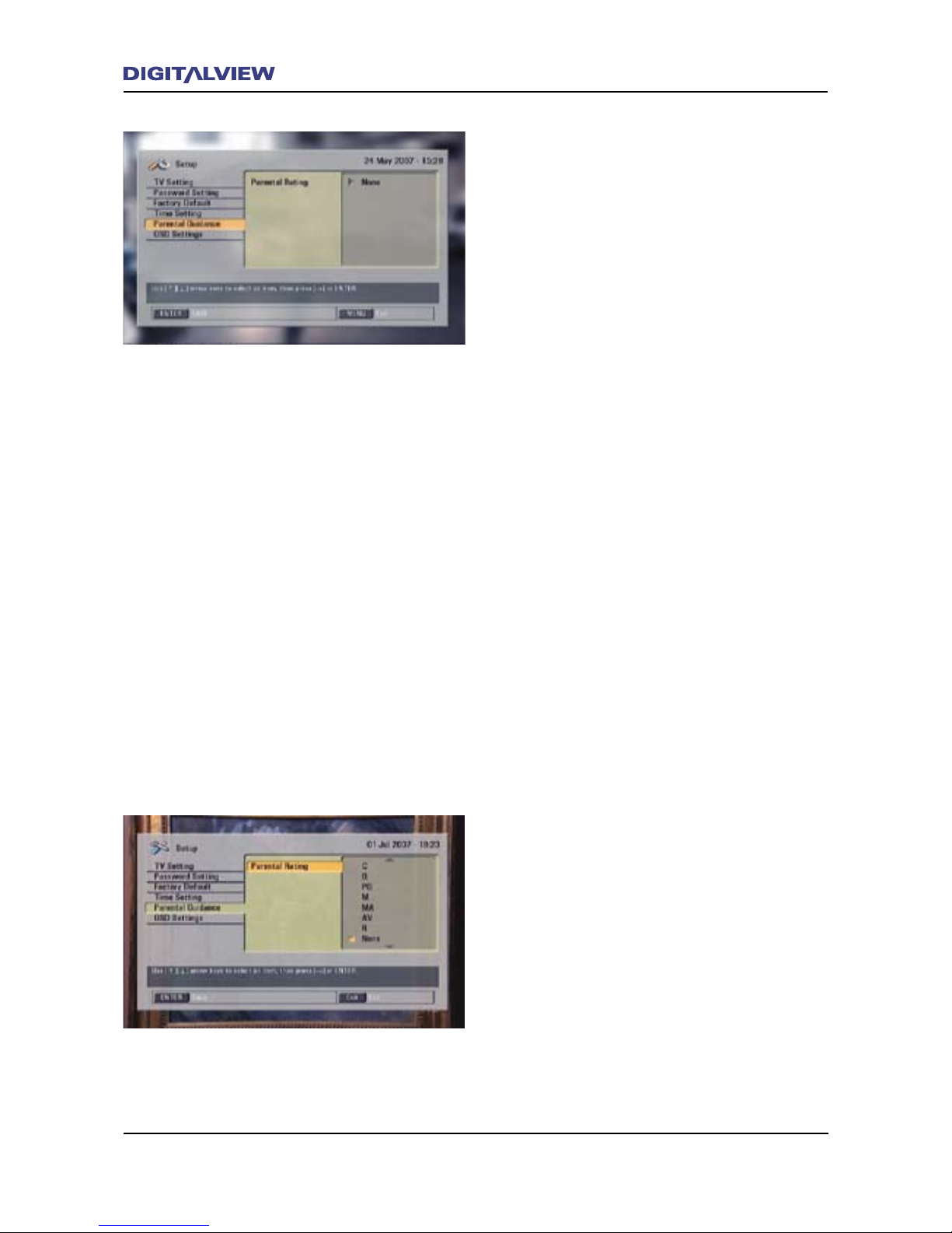
54 The Main Menu
The Main Menu 55
Parental Guidance
This option is used to block the viewing of
programs and is based on the Parental Rating
codes as specied by the Australian free-to-air
broadcasters. The Parental Rating in the order of
priority consists of eight codes:
• P - Pre-school
• C - Children
• G - General
• PG - Parental Guidance recommended
• M - Mature Audience 15+
• MA - Mature Adult audience 15+
• AV - Adult Audience (strong violence 15+)
• R - Restricted - 18+
• All – All programs
Note:
• When selecting a parental code, only the
viewing of programs above the specied
Parental Rating code will be allowed for
viewing. For example, if the C code is
specied for blocking, only programs with a
P rating will be allowed for general viewing
and not require password access. All other
codes below and including C will be blocked
and requires password access
To block a program based on the Parental Rating
codes:
1. Select Setup from the MAIN MENU and press
ENTER.
2. Select Parental Guidance using the Ç or È
buttons and press ENTER. Parental Rating is
selected.
3. Press ENTER. Unless otherwise specied,
None is selected.
4. Press the Ç or È buttons on the RCU to
highlight the Parental code required for
program blocking and press ENTER
5. Enter your current password or the default
password 0000 using the numerical buttons
on the RCU in and press ENTER
6. Press the EXIT button to clear any menus and
return to normal viewing.
Page 59
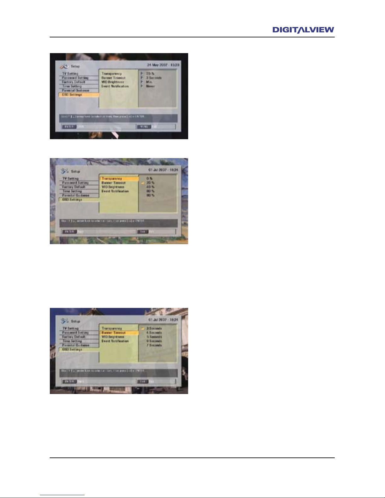
The Main Menu 55
OSD Settings
The OSD setting is used to change the OnScreen Display Transparency and Banner
Timeout settings. Included with this option is
the adjustment of the front panel display, VFD
Brightness and Event Notication reminder.
OSD Settings - Transparency
The Transparency adjustment allows the video to
show through some OSD related items (Menus and
Dialogue boxes) from opaque to 90% transparent.
1. Select Setup from the MAIN MENU and press
ENTER.
2. Select OSD Setting using the Ç or È buttons
and press ENTER. The Transparency option is
highlighted with 20% shown.
3. Press the Ç or È buttons to select the
required transparency and press ENTER.
4. Press the EXIT button to clear any menus and
return to normal viewing.
OSD Settings - Banner Timeout
The Banner Timeout is used to select the time
(in seconds), for all Menu or Dialogue boxes that
are displayed.
1. Select Setup from the MAIN MENU and press
ENTER.
2. Select OSD Setting using the Ç or È buttons
and press ENTER.
3. Select Banner Timeout using the Ç or È
buttons and press ENTER.
4. Press the Ç or È buttons to select the
required “timeout” and press ENTER.
5. Press the EXIT button to clear any menus and
return to normal viewing.
Page 60
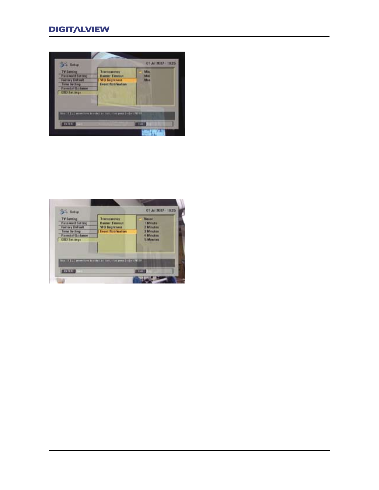
56 The Main Menu
The Main Menu 57
OSD Settings - VFD Brightness
The VFD Brightness is used adjust the brightness
of the front panel display.
1. Select Setup from the MAIN MENU and press
ENTER.
2. Select OSD Setting using the Ç or È buttons
and press ENTER.
3. Select VFD Brightness using the Ç or È
buttons and press ENTER.
4. Press the Ç or È buttons to select the
required brightness for the display and press
ENTER.
5. Press the EXIT button to clear any menus and
return to normal viewing.
OSD Settings - Event Notication
Event Notication is a feature that can be
enabled that informs the viewer of the NEXT
program to be broadcast.
1. Select Setup from the MAIN MENU and press
ENTER.
2. Select OSD Setting using the Ç or È buttons
and press ENTER.
3. Select Event Notication using the Ç or È
buttons and press ENTER.
4. Press the Ç or È buttons to select the
required time for notication, before the NEXT
program commences and press ENTER.
5. Press the EXIT button to clear any menus and
return to normal viewing.
Page 61
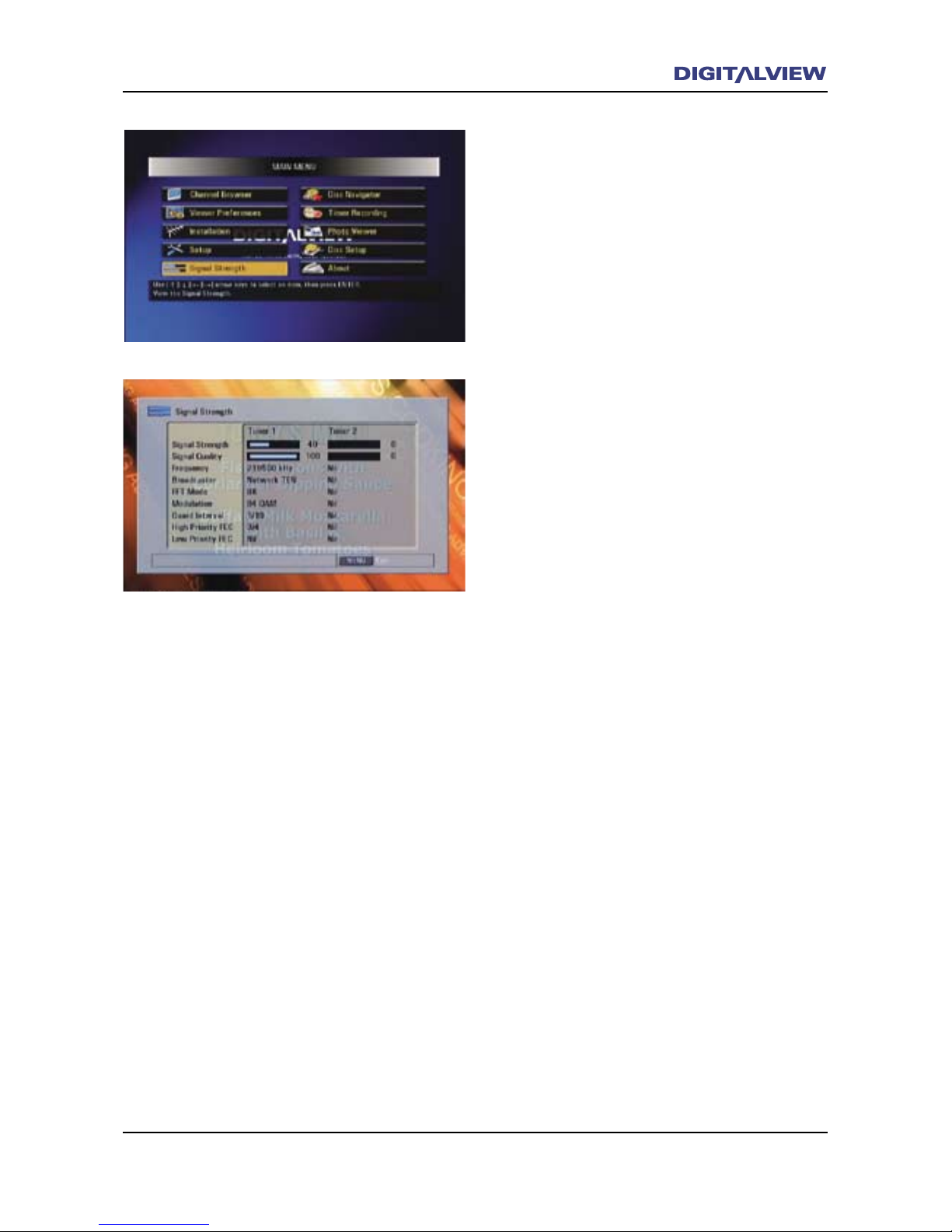
The Main Menu 57
Signal Strength
Shows summary information for both tuners. The
information is related to the currently active
services. Signal Strength should be within the
range 70-99 while Signal Quality should be
within the range 95-100.
1. Select Signal Strength from the MAIN MENU
and press ENTER.
2. A dialogue box showing the active properties
of both Tuner 1 and Tuner 2 is displayed.
3. Press the EXIT button to clear any menus and
return to normal viewing.
Page 62
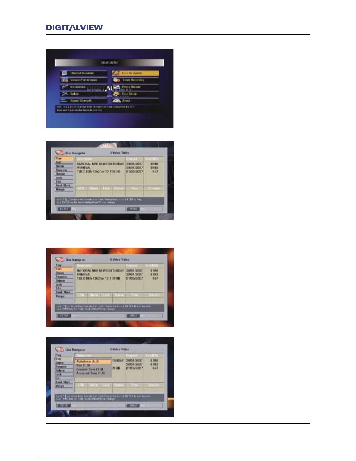
58 The Main Menu
The Main Menu 59
Disc Navigator
The Disc Navigator allows you to manage and edit
any the Recorded Titles currently stored on your
Hard Disc Drive (HDD).
Sort
The Sort option is used to organize all Recorded
Titles stored on the HDD. There are categories
to select from. These include Alphabetic,
Size, Created Time and Accessed Time. Once
congured, use the Channel Browser or Photo
Viewer to view the sorted order. Refer to the
section on The Channel Browser and Photo
Viewer.
1. Select Disc Navigator from the MAIN MENU
and press ENTER.
2. Select Sort using the Ç or È buttons and
press ENTER. A dialogue box shows the Sort
options.
3. Alphabetic A-Z sorts the Recorded Titles on
your HDD in alphabetic order starting with
(A). To conrm this option press ENTER.
or
Press the Å or Æ buttons to reverse the order
of Sorting – Alphabetic Z-A. All Recorded
Titles and photos will now be sorted in the
order starting with (Z). To conrm this option
press ENTER.
Play
Select this option to Play a recorded title.
1. Select Disc Navigator from the MAIN MENU
and press ENTER.
2. Select Play using the Ç or È buttons and
press ENTER.
3. Select a title using the Ç or È buttons and
press ENTER. The title starts to play.
Note:
• As an alternative consider using the REC LIST
button to select and playback a recorded
title.
Page 63
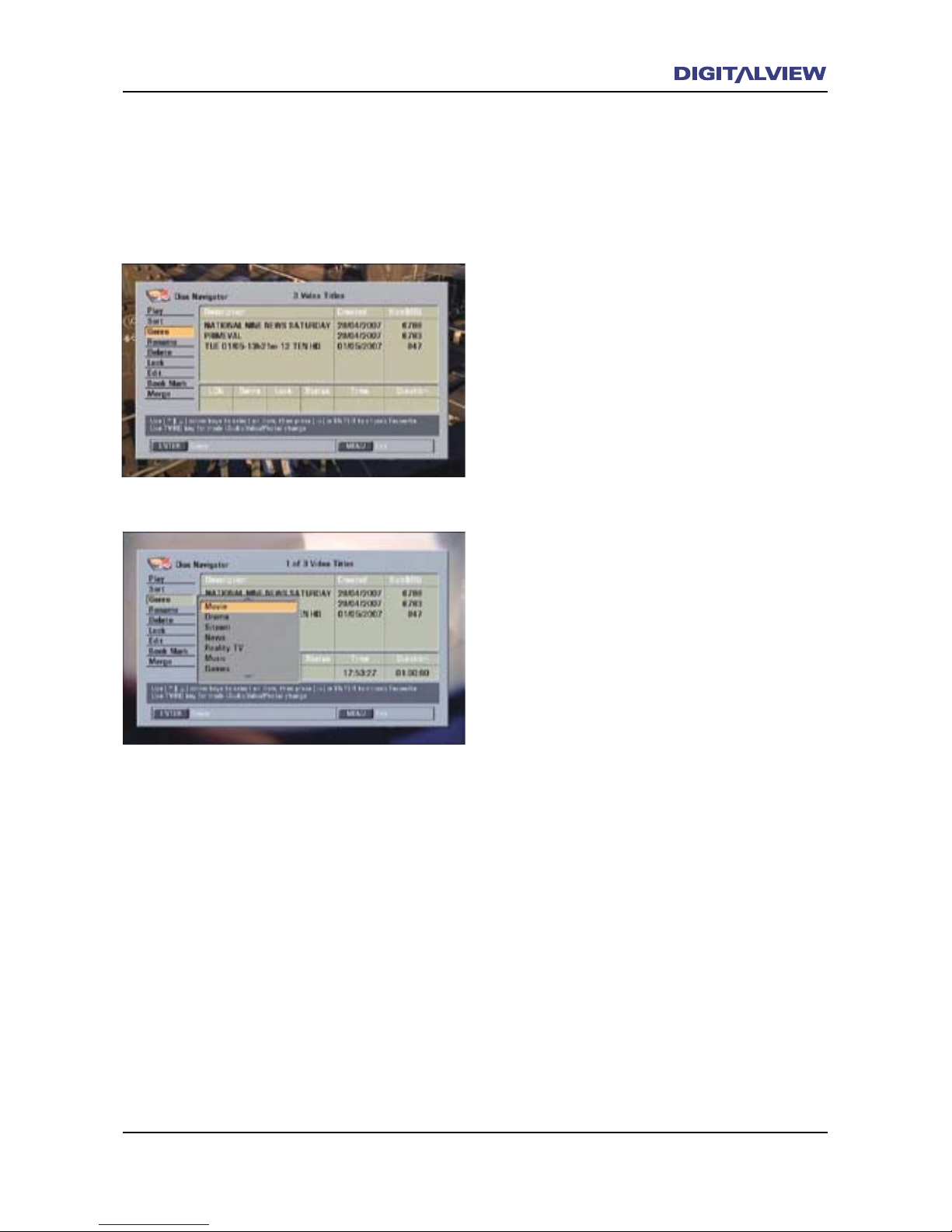
The Main Menu 59
Use the same procedure as above for the other
Sort options Size, Created Time and Accessed
Time.
4. Press the EXIT button to clear any menus and
return to normal viewing.
Genre
Genre is used as another form of sorting to
classify a Recorded Title according to the type of
program, i.e. Sports, Drama etc. Genre is useful
when searching the HDD for Recorded Titles with
a specic theme.
1. Select Disc Navigator from the MAIN MENU
and press ENTER.
2. Select Genre using the Ç or È buttons
and press ENTER. The rst Recorded Title is
highlighted.
3. Select a Recorded Title to assign a Genre
classication to using the Ç or È buttons.
4. Press the Æ button. A dialogue box showing
the Genre classications is displayed.
5. Select a classication using the Ç or È
buttons and then press the Æ button. A star
indicates that the Recorded Title has been
classied.
6. Press ENTER to conrm the classication or
press Å to return the selected title.
7. Once all Genre classications have been
entered, press the EXIT button to clear any
menus and return to normal viewing.
To view the Genre classications you have
specied for Recorded Titles, press the REC LIST
on the RCU. Follow the instruction in Playback a
Recorded Title Using Genre
Page 64
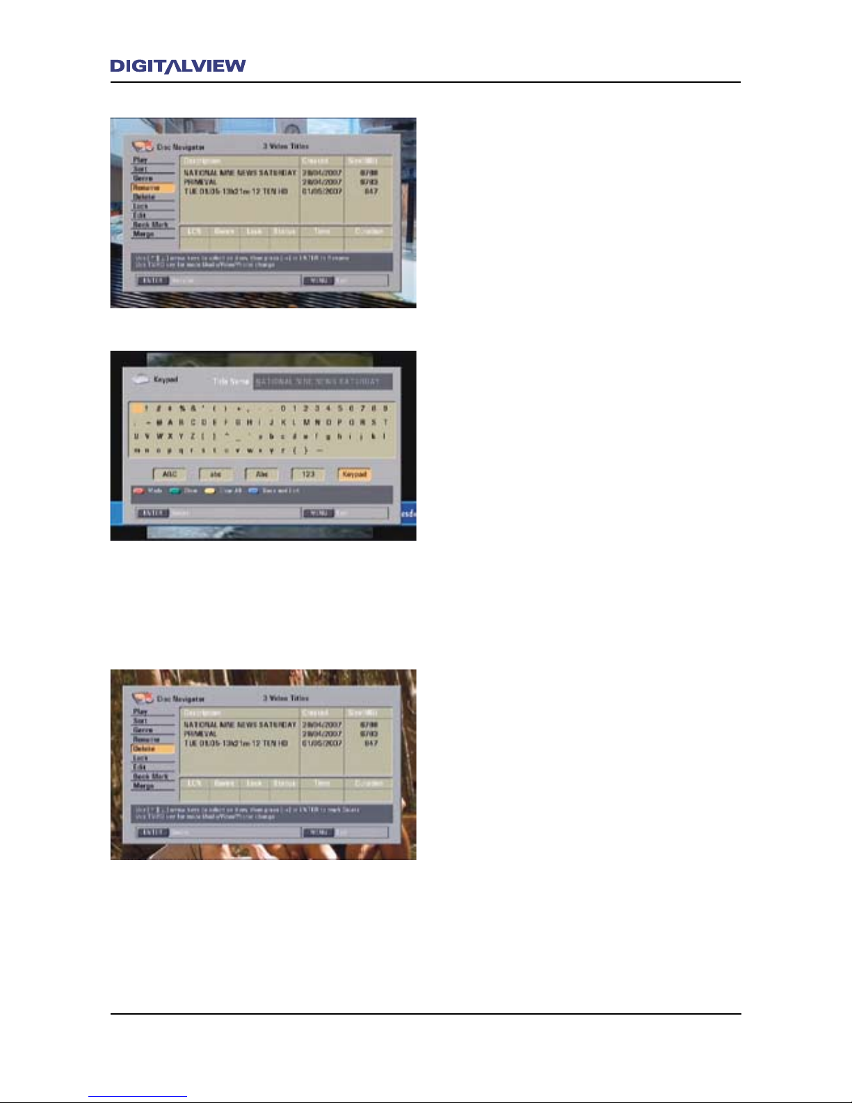
60 The Main Menu
The Main Menu 61
Rename
Each Recorded Title has a program name or
identication associated with it. The Rename
option allows you to change program name or
identication.
1. Select Disc Navigator from the MAIN MENU
and press ENTER.
2. Select Rename using the Ç or È buttons
and press ENTER. The rst Recorded Title is
highlighted.
3. Select a Recorded Title to Rename using the
Ç or È buttons.
4. Press ENTER. A discrete alphanumeric keypad
is displayed with the title editing window
above it. If needed, pressing the RED button
can change the keypad style and character
format. The GREEN and YELLOW buttons are
used to clear single characters or the full title,
respectively.
5. Enter the new name for the Recorded Title and
press the BLUE button to Save and Exit.
6. Repeat steps 1-5 for other titles if required.
7. Press the EXIT button to clear any menus and
return to normal viewing.
Delete
Use Delete to remove any Recorded Titles stored
on the HDD. Using this option allows you to
select one or more Recorded Titles for deletion.
Alternatively, to Delete single les only, use the
REC LIST function. Refer to Deleting a Single
Recorded Title Using the Record Browser.
1. Select Disc Navigator from the MAIN MENU
and press ENTER.
2. Select Delete using the Ç or È buttons
and press ENTER. The rst Recorded Title is
highlighted.
3. Select a Recorded Title to Delete using the Ç
or È buttons.
Page 65
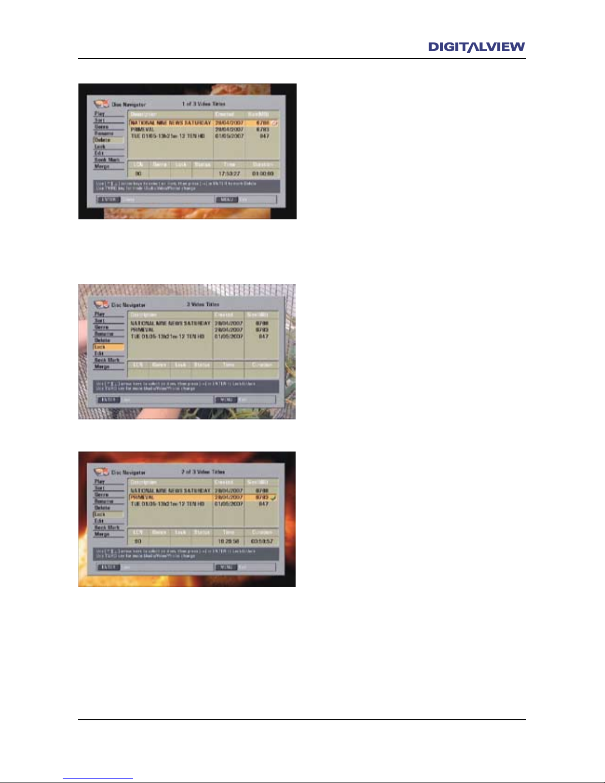
The Main Menu 61
4. Press the Æ button. V is shown next to the
Recorded Title that will be deleted.
5. To delete multiple Recorded Titles follow steps
3 & 4.
6. Press ENTER. A conrmation dialogue box is
displayed.
7. Conrm Delete by selecting Yes.
8. The specied Recorded Title is deleted.
9. Press the EXIT button to clear any menus and
return to normal viewing.
Lock
Use Lock to prevent the viewing of any Recorded
Titles. A password is required to permit viewing
or Unlocking once the Recorded Title is Locked.
1. Select Disc Navigator from the MAIN MENU
and press ENTER.
2. Select Lock using the Ç or È buttons and
press ENTER. The rst Recorded Title is
highlighted.
3. Select a Recorded Title to Lock using the Ç
or È buttons.
4. Press the Æ button. P is shown next to the
Recorded Title that will be locked.
5. Press ENTER. A conrmation dialogue box is
displayed.
6. Conrm Lock by selecting Yes.
7. The specied Recorded Title is now locked and
requires password access.
8. Press the EXIT button to clear any menus and
return to normal viewing.
To unlock a Recorded Title, follow the same
procedure as above.
Page 66
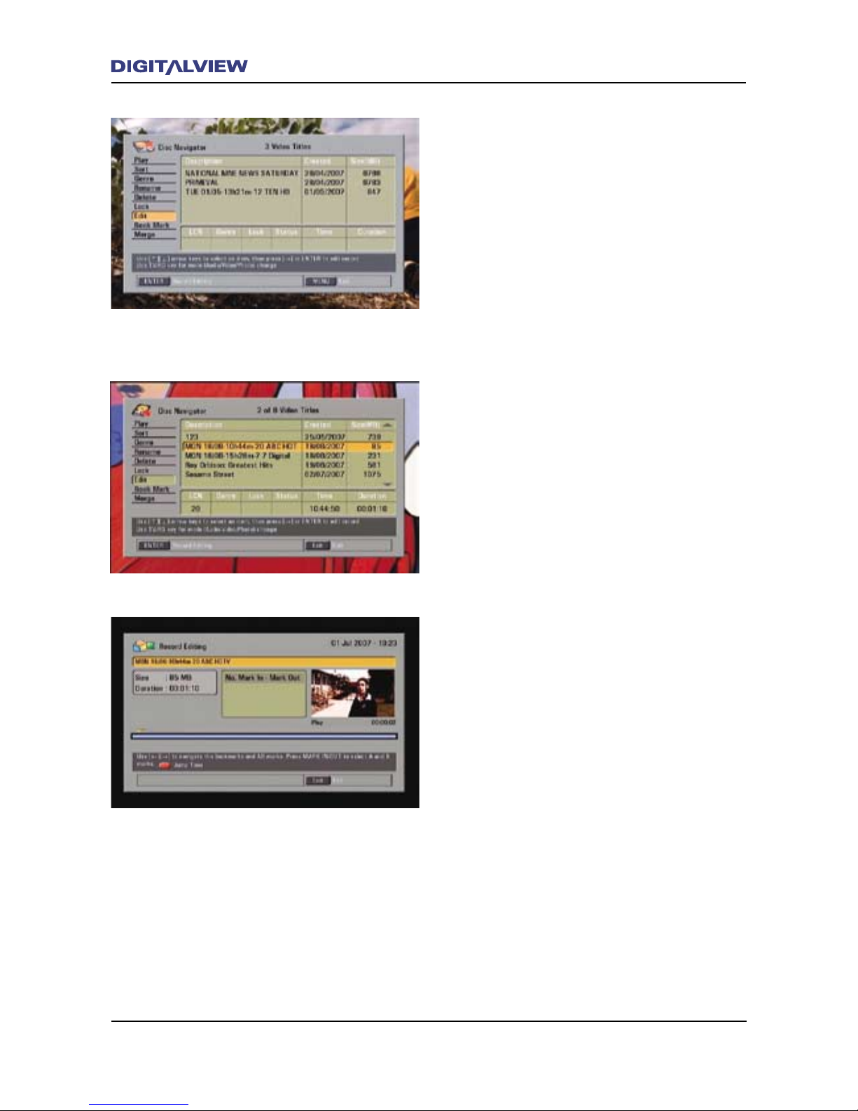
62 The Main Menu
The Main Menu 63
Edit
The DVR-810 provides an easy to use feature
for deleting any selected part (segment) of a
Recorded Title. Each segment is referred to
as an AB Mark. Editing allows either a single
AB segment or multiple AB segments to be
deleted. Caution: Using the Editing feature will
permanently delete any segment or segments
which cannot then be recovered.
1. Select Disc Navigator from the MAIN MENU
and press ENTER.
2. Select Edit using the Ç or È buttons and
press ENTER. The rst Recorded Title is
highlighted.
3. To select a Recorded Title use the Ç or È
buttons.
4. Press ENTER. The Record Editing dialogue
box is displayed and the Recorded Title starts
to play in the Video Preview Window.
The Record Editing main dialogue box is split
into the following sections and shows the
Recorded Title information and specic editing
options:
• Title
• Size and Duration - dialogue box
• Jump Time - dialogue box (Only shown if
activated using the JUMP TO button)
• No. (Number) Mark In – Mark Out - dialogue
box or (AB segments)
• The Video Preview Window
• The Editing Timeline
Below the Video Preview Window is the current
playback mode and real time clock status display,
including the Editing Timeline - (blue bar with
a yellow cursor). The Editing Timeline displays
the total time duration of the Recorded Title
including any specied AB segments. The
cursor is used in conjunction with the Timeline
to display the current playback position of the
Recorded Title and also while editing, the A or B
segment points.
Page 67
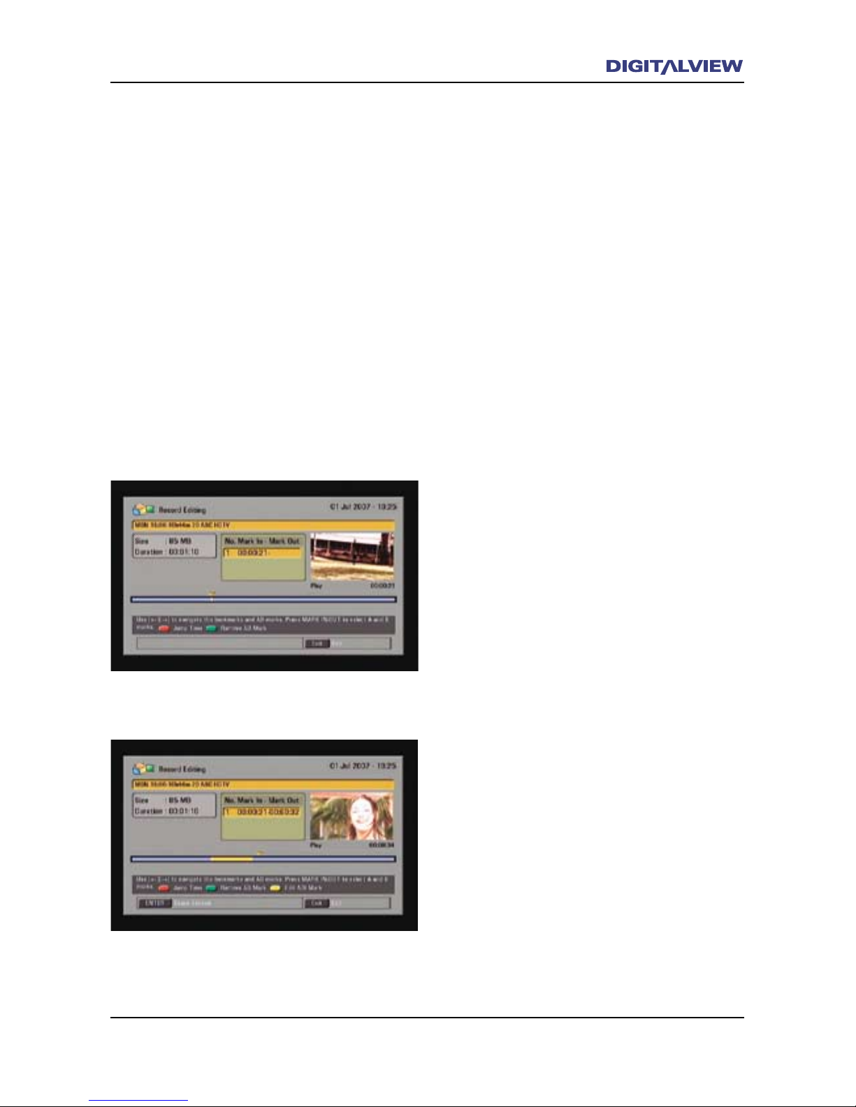
The Main Menu 63
All details of the AB segments that you specify
for deletion are shown within the Timeline and
also in the Mark In – Mark Out section. To
move or pause within the Timeline use either
or both, the Transport Control buttons and/or
the Jump Time option. The Jump Time option
is displayed when the JUMP TO button on the
RCU is pressed. For more information on the
Transport Control buttons refer to the section on
Trick and Transport Control Modes.
Note:
• If Jump Time is used while editing, ensure
to disabled it before attempting to conrm
any AB segment deletion. Deleting is
not possible if the Jump Time option is
displayed. To disable the Jump Time option
press the JUMP TO button. Jump Time
should not now be displayed.
Editing a Recorded Title
1. After selecting the Recorded Title, playback
commences from the beginning in the Video
Preview Window.
2. To edit the Recorded Title from the very start
of the title, press the 9REVERSE CONTROLLED
SKIP button until TITLE START is shown in the
status display. The Recorded Title pauses.
3. Press 4PLAY to start playing the title. Use
the Transport Controls and/or the JUMP TO
button to move to the required start position
in the Timeline.
• If the JUMP TO button is pressed, the Jump
Time dialogue box is displayed. Enter the
appropriate time value in (Hours:Minutes:
Seconds) using the numeric keypad on the
RCU.
4. Press the MARK IN/OUT button. This is the
Mark IN or A position from where the deletion
will start.
5. Continue playing the Recorded Title or use the
Transport Controls and/or the JUMP TO button
to move to the required end position in the
Timeline.
6. Press the MARK IN/OUT button again. This
is the Mark Out or B position to where the
deletion will end. This is now the AB segment
marked for deletion.
Page 68
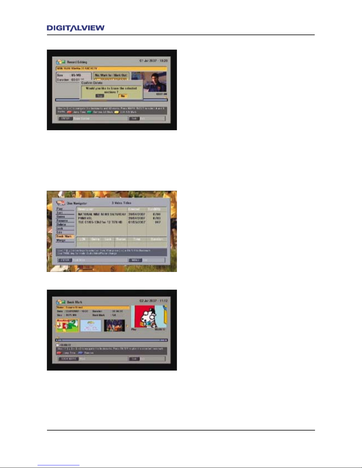
64 The Main Menu
The Main Menu 65
• Each AB segment is displayed in the No.
Mark In – Mark Out dialogue box. This
dialogue box displays all the specied AB
segments. Any AB segment can be re-edited
or cleared by selecting it from the No. Mark
In – Mark Out dialogue box. Use the Ç
or È buttons to select the AB segment,
together with either the GREEN (Remove AB
Mark) or YELLOW (Edit AB Mark) buttons.
7. The Recorded Title continues to play. If
required use the same procedure as in steps
1-6 to specify additional segments to delete.
8. When nished press ENTER. Conrm Yes or No
to delete the AB segment/s.
9. Press the EXIT button to clear any menus and
return to normal viewing.
Book Mark
The Book Mark option is used to edit or remove
any “Bookmarks” that were previously inserted
while recording or during playback. The Book
Mark menu option can also be used to add
“Bookmarks” to a Recorded Title where no
previous “Bookmarks” were inserted. Refer to
section, Bookmarking During Recording or
Playback.
1. Select Disc Navigator from the MAIN MENU
and press ENTER.
2. Select Book Mark using the Ç or È buttons
and press ENTER. The Book Mark main
dialogue box is shown with the rst Recorded
Title highlighted.
The Book Mark main dialogue box shows
the Recorded Title information and specic
editing options which include:
• Title
• Date, Size, Duration and Number of
Bookmarks
• Thumbnail Picture of each of the inserted
Bookmarks
• The Video Preview Window
Page 69
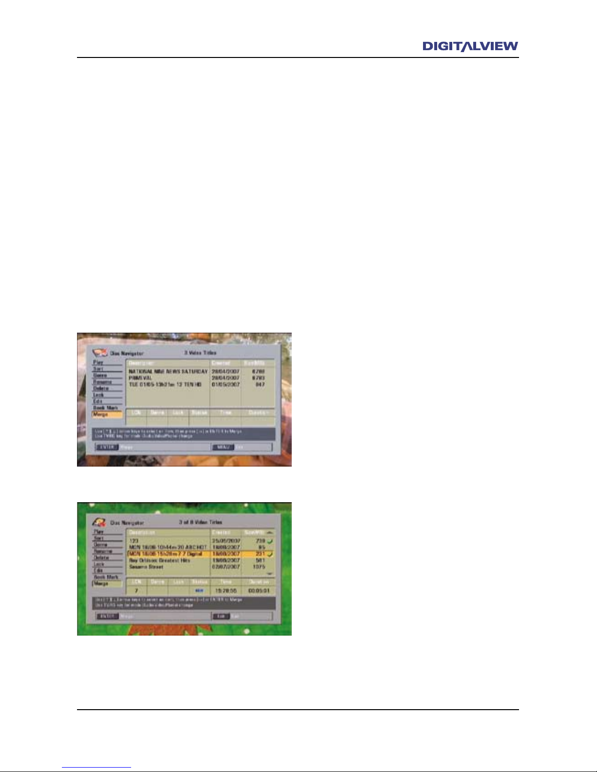
The Main Menu 65
• The Editing Timeline including the positional
display of any Bookmarks.
3. Choose one of the Recorded Titles in the list
using the Ç or È buttons and press ENTER.
Playback of that Recorded Title commences
from the beginning, in the Video Preview
Window.
4. To Remove a Bookmark use the Å or Æ
buttons to select a Thumbnail Picture. Press
the BLUE button on the RCU to remove the
Bookmark.
5. To insert a Bookmark use the Transport Control
buttons to navigate within the Timeline.
6. Select a point on the Timeline and press the
BOOKMARK button on the RCU.
6. Press the EXIT button to clear any menus and
return to normal viewing.
Merge
The Merge option allows two Recorded Titles to
be combined.
1. Select Disc Navigator from the MAIN MENU
and press ENTER.
2. Select Merge using the Ç or È buttons
and press ENTER. The rst Recorded Title is
highlighted.
3. Select the rst Recorded Title for Merging,
using the Ç or È buttons. The name of the
merged title will use the name of rst selected
Recorded Title.
4. Press the Æ button to select it. P is shown
next to the Recorded Title.
5. Select the second Recorded Title for Merging,
using the Ç or È buttons.
6. Press the Æ button to select it. P is shown
next to the second Recorded Title.
7. Press ENTER. The two Recorded Titles are now
merged and is listed in the REC LIST.
Page 70
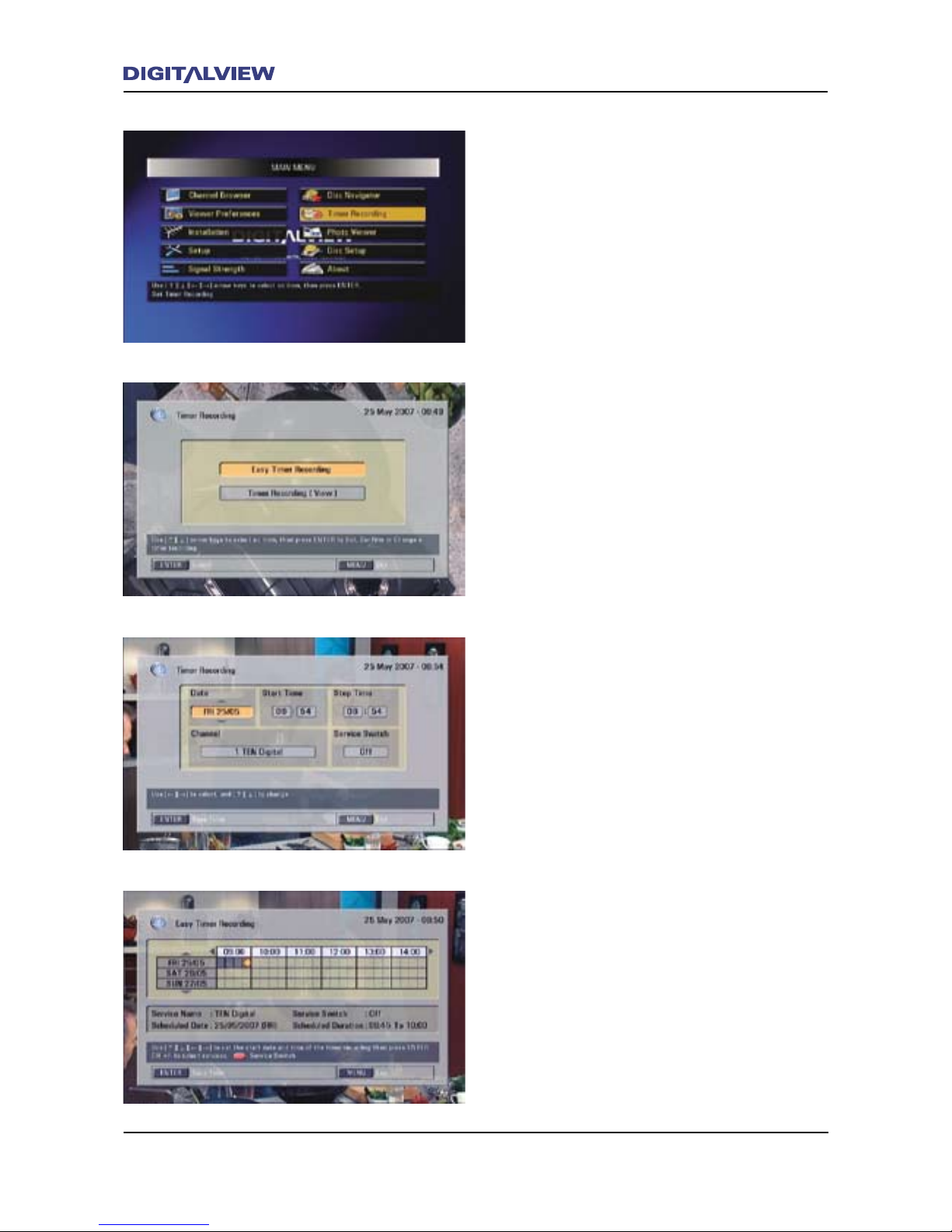
66 The Main Menu
The Main Menu 67
Timer Recordings
Use this option for unattended scheduled
recording. EASY TIMER and TIMER REC functions
can also be accessed using the Timer Recording
menu, or the nominated buttons on the RCU.
For detailed information, refer to the following
sections in this manual.
Timer Recording main dialogue box. Refer to
the section - To Record Programs Using the
Schedule Timers.
Timer Recording TIMER REC dialogue box.
Refer to the section - Using the TIMER REC
Function.
Timer Recording EASY TIMER dialogue box.
Refer to the section - Using the EASY TIMER
Function.
Page 71
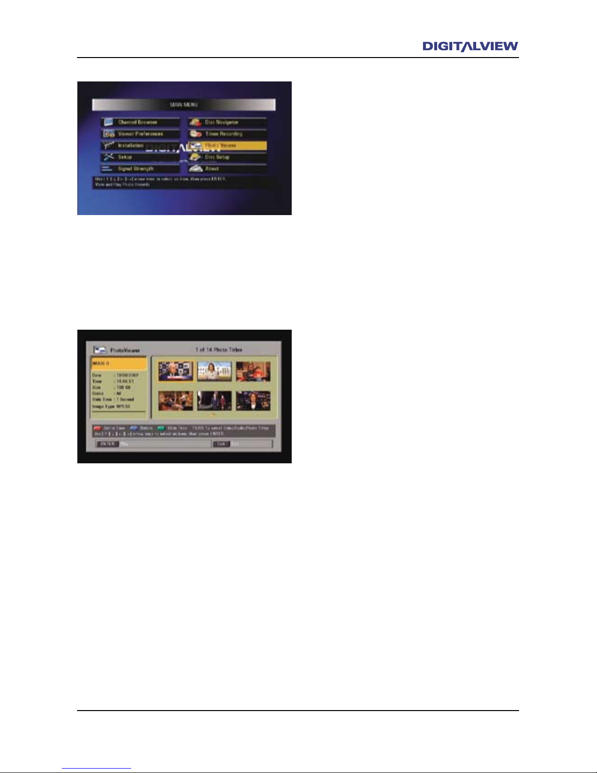
The Main Menu 67
Photo Viewer
Conguring the Photo Viewer
The Photo Viewer option is used to playback any
screen captured video frames. Each captured
video frame is dened as a Photo Capture. Refer
to the section on Photo Capture and Playback.
All screen captured Photos are stored in a single
le location and are accessed by using the Photo
Viewer. All Photos are viewed as a slideshow. In
other words, each Photo is played in sequence
with a preset time between each Photo and
starting from the rst selected Photo.
The preset time for viewing the photo slideshow
can be adjusted in the Photo Viewer – Slide
Time dialogue box.
Adjusting the Preset Time
1. Select Photo Viewer from the MAIN MENU
and press ENTER.
2. Press the GREEN button on the RCU. The
Slide Time dialogue box is highlighted,
showing the current viewing time for each
Photo.
3. Press the Å or Æ buttons to change the
preset time and press ENTER.
4. Press the GREEN button again to accept the
new preset time. The new preset time now
applies to any subsequent Photos that may be
viewed.
Delete a Photo
1. While in the Photo Viewer, press the Å or Æ
to select the Photo to be deleted.
2. Press the BLUE button on the RCU to delete
the selected Photo.
3. Conrm Yes or No.
Page 72
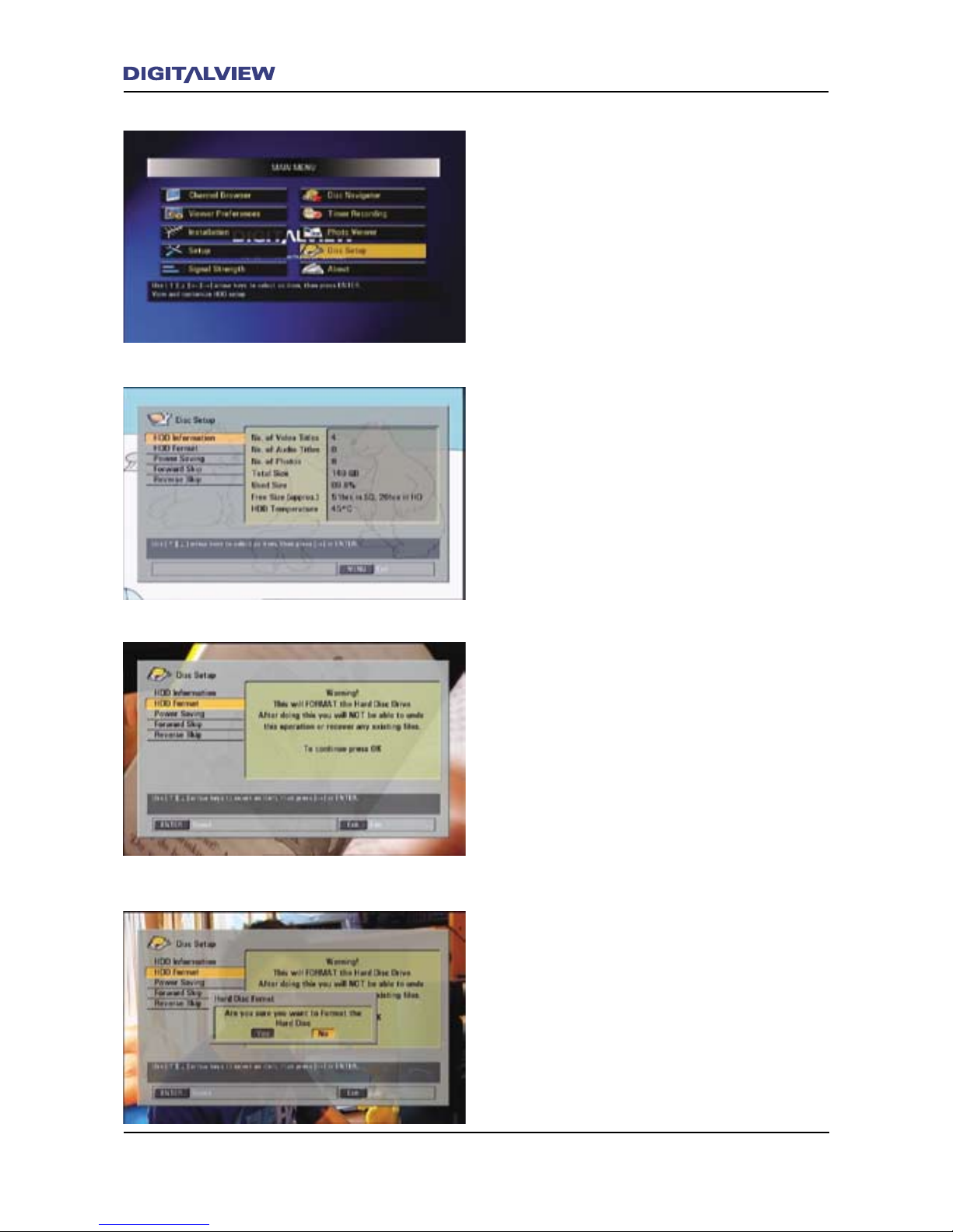
68 The Main Menu
The Main Menu 69
Disc Setup
Using Disc Setup
The Disc Setup allows for specic conguration
settings of the Hard Disc Drive (HDD) and basic
Transport Control options.
HDD Information
Displays information related to the current Hard
Disc Drive conguration including the number
of Recorded Titles, remaining HDD size and HDD
temperature.
HDD Format
Formatting, essentially congures the HDD for
the recording and storage of data. Caution: When
the HDD format option is used, all les stored
on the HDD are deleted and cannot then be
recovered.
1. Select Disc Setup from the MAIN MENU and
press ENTER.
2. Select HDD Format using the Ç or È buttons
and press ENTER.
3. Enter your or the default password – 0000
using the numeric keypad on the RCU.
4. Conrm Format by selecting Yes.
5. Press the EXIT button to clear any menus and
return to normal viewing.
Page 73
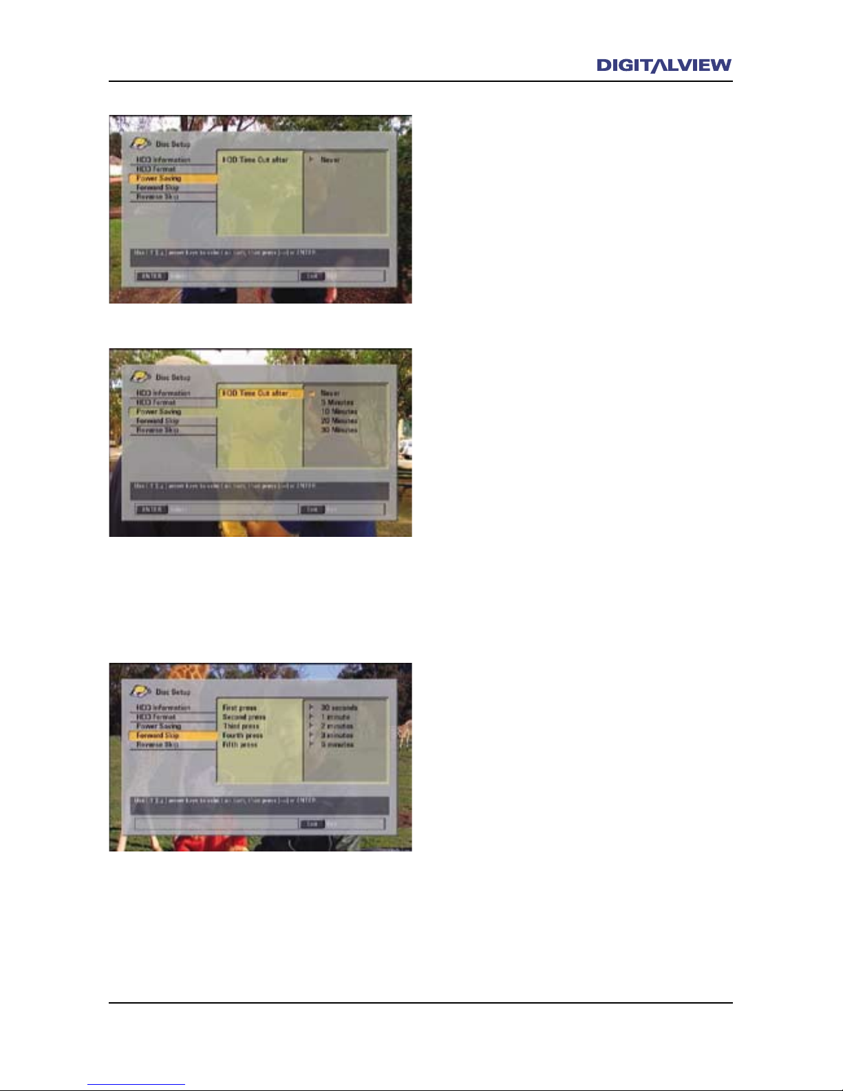
The Main Menu 69
Power Saving
The Power Saving option provides a means of
shutting the HDD off after a preset time and
while no recording or playback is in progress.
This is referred to as the HDD Time Out. This
type of HDD management is used to increase
the reliability of the HDD over its operational
lifetime. A brief delay is introduced as a result
of the HDD Time Out setting when the start of
recording or playback is initiated.
Forward Skip
During recording or playback the :Forward
Skip button is used to move a preset time, in
seconds or minutes, ahead in the program title.
In the case where recording is in progress,
Forward Skip can only be used if the program
title is in Chase mode. Refer to the section on
Chase and Chase Play. There are 5 incremental
preset times associated with the :Forward Skip
button including Title Start. Each button press
determines how far forward the program title
moves from its current position. The :Forward
Skip incremental preset times can be changed to
suit your viewing requirements.
1. Select Disc Setup from the MAIN MENU and
press ENTER.
2. Select Power Saving using the Ç or È
buttons and press ENTER.
3. Enter yours or the default password, – 0000
using the numeric keypad on the RCU. HDD
Time Out after shows the current timeout
value.
4. Press ENTER. The current timeout value is
highlighted.
5. Press the Ç or È button to select the new
timeout value and press ENTER.
6. Press the EXIT button to clear any menus and
return to normal viewing.
Page 74
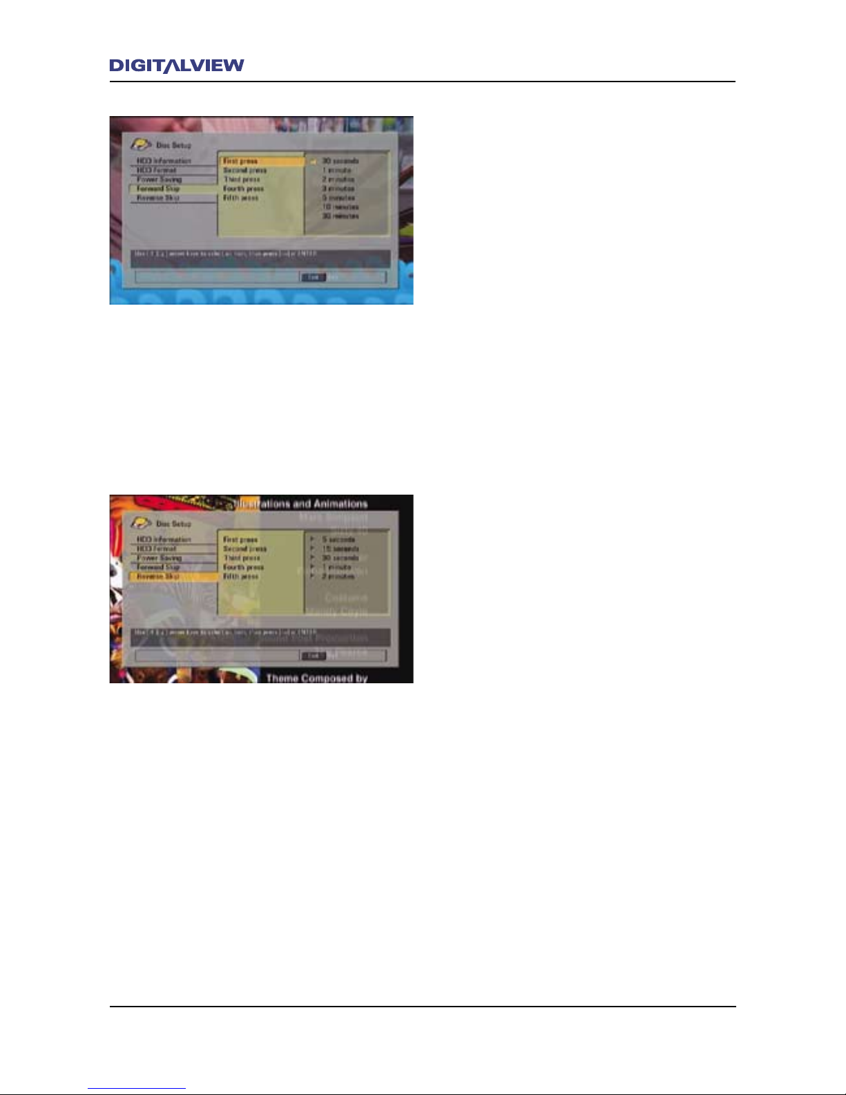
70 The Main Menu
The Main Menu 71
1. Select Disc Setup from the MAIN MENU and
press ENTER.
2. Select Forward Skip using the Ç or È
buttons and press ENTER. The First Press
button assignment is highlighted together
with the selected preset time.
3. Press ENTER.
4. Press the Ç or È button to select the new
preset value and press ENTER.
5. If required, press the Å button to select
Second Press. The Second Press button
assignment is highlighted together with the
selected preset time.
6. Press the Ç or È button to select the new
preset value and press ENTER.
7. If required, repeat steps 5 & 6 for the
remaining button presets.
8. Press the EXIT button to clear any menus and
return to normal viewing.
Reverse Skip
During recording or playback the 9Reverse Skip
button is used to move a preset time, in seconds
or minutes, backward in the program title. Also,
refer to the section on Chase and Chase Play.
There are 5 incremental preset times associated
with the 9Reverse Skip button including Title
End. Each button press determines how far
backward the program title moves from its
current position. As with :Forward Skip, the
9Reverse Skip incremental preset times can
be changed to suit your viewing requirements.
Follow the procedure as in Forward Skip to
change the button preset times.
Page 75
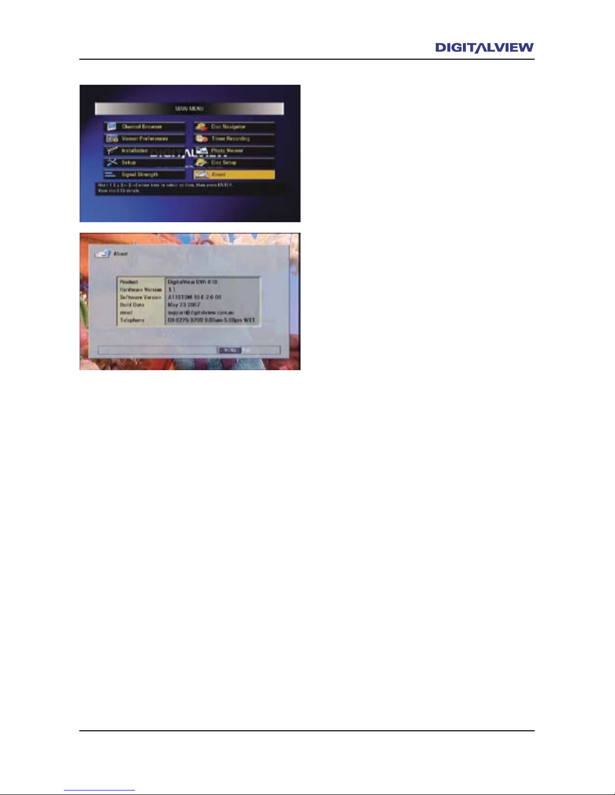
The Main Menu 71
About
Information associated with the DVR-810
hardware and software including contact details.
Page 76
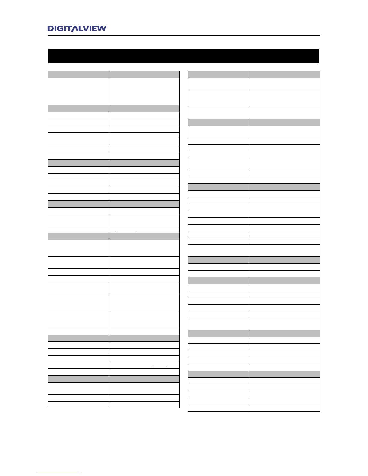
72 Specications
Specication
DTTB Standard
Type
Australian DVB-T & MPEG-2 Compliant. In
accordance with Australian AS4933.1.2005
and ETSI300744. MPEG-4 / H-264 in new
Australian Draft Specication and not yet fully
dened.
Front End Dual Tuner Inputs
Number of DVB-T Tuners 2
Frequency Coverage VHF/UHF : 174MHz to 858MHz
IF Bandwidth 7MHz
Channel Offset +/- 125KHz
Input Signal Sensitivity < 28dbuV
Antenna Input 75 ohm Female IEC-Connector
Loop Output 75 ohm Male IEC-Connector
Front End Demodulator
Demodulation COFDM
COFDM Spectrum 2K/ 8K Non-Hierarchical and Hierarchical
Modulation Modes QPSK, 16QAM, 64QAM
Guard Interval Modes 1/32, 1/16, 1/8, 1/4
FEC Modes Rate 1/2, 2/3, 3/4, 5/6, 7/8
MPEG Transport Stream Demultiplex
Video 80 Mbits/s max
Audio
768 kbits/s max - AC3 5.1 and Stereo, MPEG1/
2 Stereo and Mono
PIDs 32 Simultaneously
Video Decoding
Compression Type - MPEG-2
MPEG-2 MP@ML Standard Denition, MP@HL
High Denition (AS-4599) (EN300468) (ISO/IEC
13818-2).
Compression Type - MPEG 4 / H.264/
AVC
H264, ISO/IEC 14496 Part10
Display Aspect Ratio 1 (16:9 Display) 16:9, 4:3 Pillarbox
Display Aspect Ratio 2 (4:3 Display) 4:3, 4:3 Letterbox
SD Resolution Analog - Video Output
(Interlaced Only)
Y/C (S-Video) - 576i x 720 and CVBS, 576i
x 720
RGB/HV HD Resolution Analog - Video
Output (Interlaced and Progressive
@ 50Hz
1080i x 1920/28.125kHz, 720p x 1280/
37.50kHz, 576p x 720/31.25kHz
Y/Pb/Pr HD Resolution Analog - Video
Output (Interlaced and Progressive @
50Hz
1080i x 1920, 720p x 1280, 576p x 720
HD Resolution Digital - HDMI 1080i x 1920, 720p x 1280, 576p x 720
Video Connections
CVBS 1 x RCA
Y/C (S-Video) 1 x 4 pin mini-DIN receptacle
Y/Pb/Pr 3 x RCA receptacle
RGB/HV 15 pin High Denisity “D-SUB” receptacle
HDMI HDMI Type A (Ver 1.1)
Audio Decoding
Compression Type
MPEG-1 Layer 2, Single, Dual, Joint Stereo,
Stereo (ISO/IEC 11172-3) - Dolby Digital AC-3
Frequency Response 20Hz~ 20 kHz, < ±2dB
Sampling Frequencies 32, 44.1, 48kHz
Audio Connections
Audio Analog - MPEG 1 Layer 2 (Left
and Right)
2 x RCA
Audio Digital Coaxial - MPEG 1 Layer
2 and AC3 Dolby Digital (S/PDIF) loop
through
1 x RCA
Audio Digital Optical - MPEG 1 Layer 2
and AC3 Dolby Digital
1 x Toslink
Receiver Functionality
Channel Groups for Fast Channel/
Service Selection
Pre-assigned on Initial Scan or User Assignable
Dual Tuner Viewing Picture-In-Picture (PIP) - Preview Quality
Closed Captions / Teletext YES
Now/Next Program display YES
Extended Now / Next Program
Information
YES
7 Day EPG Support YES
Next Program Prompt YES
DVR Functionality
Hard Drive Size 160 - 500Gb
Hard Drive Type SATA
Max record time Dependent on HDD Capacity
Recording Quality Broadcaster Native
Dual Program Viewing PIP Live TV and Recorded Titles
Video Editor Multiple MARK IN - MARK OUT with Delete
Recording and Playback Bookmarks 8 with Thumbnail Index and Editable
Front Panel Transport Functions Play/Pause, Record, FF, Rew, Stop
Jump
Any Absolute Time within the Recording or
Playback Title Length
Remote Control
Control Automation (Crestron, AMX, RTI) RS232C / V24
Remote IR Extender IR Receiver with 3 metre cable (optional)
Physical Characteristics
Front Panel and Housing Color Black
Remote Control Unit/Battery 55 Key / 2x AAA
Size (W)430.00 x (D)296 x (H)92
Weight (Net) 3.75kg
Front Panel Display 16 character VFD with annunciators
Front Panel Buttons
8 (Standby, Menu, Exit, Rew, FF, Rec, Play/
Pause, Stop)
Electrical
Input Voltage Range / Freq 180 - 265VAC / 47-60Hz
Power in Stand-by < 5W
Conducted / Radiated RFI In accordance with CISPR13 / CISPR22B
Power in Operation (max.) 22W
Safety In accordance to IEC60065
Environment
Operating Temperature 0 - 50 °C
Storage Temperature -10 ~ +60 °C
Operating Humidity 5% ~ 90 % Non-condensed
Ventilation / Cooling Thermostatically operated fan.
Operating Noise Level 28dbA with fan ON
Page 77

THIS IS THE INSIDE REAR COVER PAGE WHICH IS BLANK
NO PRINTING ON THIS PAGE
Page 78

Digitalview (Australia), 5 Bookham Street, Morley, Western Australia, Australia, 6062
Tel: 08-9275-9700 Fax: 08-9275-9717 www.digitalview.com.au
Digitalview is a business unit of Control Dynamics Pty. Ltd www. controldynamics.com.au.
Pub. CDHG22805.V1.1
 Loading...