

Page 1

Video Converter, AVX-1920
MANUAL
V1.0
Page 2
Table of Contents
................................................................................1 Introduction 3
..............................................................................................................1.1 AVX-1920 Key Features 3
................................................................................................................1.2 Guide to the AVX-1920 4
.........................................................................................2 Setup 5
........................................................................................................................2.1 Basic Setup Notes 5
....................................................................................................................2.2 Operation & Control 6
Revision History
Amendment Date
Version
August 2009
V1.0
© Digital View Ltd 2009
www.digitalview.com
Page 2 of 33
Page 3

1 Introduction
The AVX-1920, a video converter and image processor, that turns a display or
projector with a HDMI input into a powerful video display system with advanced
features such as remote operation, flexible picture in picture, a wide range of
color and image management functions as well as remote device control.
1.1 AVX-1920 Key Features
12-bit internal video processing with 10-bit color output
The AVX-1920 can output over 1 billion colors achieving unprecedented quality
with the sharpest color.
Picture in Picture (PIP)
The AVX-1920 provides various scalable picture in picture modes, video-by-video
& video-by-PC that enabling true format messaging applications.
On-Screen Markers
An innovative feature for specialist market needs the AVX-1920 supports input
linked on-screen markers.
Advanced Image Control
A wide range of image and color management tools that give an unprecedented
level of control and flexibility.
Wide Range of Inputs
The AVX-1920 supports HDMI, DVI, VGA, Component video, S-video and
Composite video – with HDCP support on HDMI & DVI ports. Resolutions
supported include all standard resolutions up to 1920x1080 (1080p).
Superior Professional Class Image Scaling
With powerful image up-scaling and down-scaling the AVX-1920 ensures input
signals are adapted to whatever display is used.
Leading-Edge De-Interlacing
For both standard definition and HD resolutions the AVX-1920 utilizes the latest
de-interlacing algorithms to ensure optimal quality output.
Selectable Output Resolutions
The AVX-1920 supports the native resolutions of all standard displays and
projectors on the market.
© Digital View Ltd 2009
www.digitalview.com
Page 3 of 33
Page 4
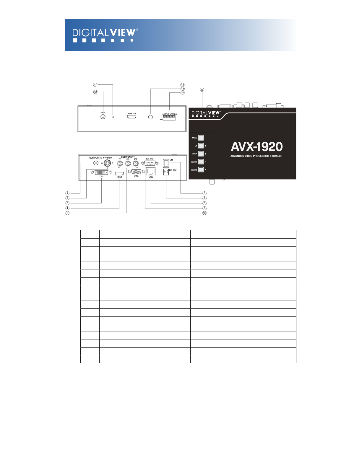
1.2 Guide to the AVX-1920
Diagram 1 – AVX-1920
Item
Description
Type / Use
1
Composite Video input
RCA jack (yellow)
2
S-Video input
Mini DIN 5-pin connector
3
DVI input
DVI-D connector
4
HDMI input
HDMI type A connector
5
Component Video (YPbPr) input
RCA jack x3 (Red, Green, Blue)
6
Power On/Off switch
Rocker switch
7
12V DC power input
2.5mm power jack, center positive
8
Network, Ethernet
RJ45 connector
9
Serial port, RS-232
DB-910VGA input
VGA DB-15-F connector
11
Power LED
On (green) / Off (clear)
12
Digital Audio output (SPDIF)
RCA jack (white)
13
HDMI output
HDMI type A connector
14
IR sensor
For use with DV remote control handset
15
Dip switch (8-pos)
Display output selection
16
Control buttons
OSD menu control
© Digital View Ltd 2009
www.digitalview.com
Page 4 of 33
Page 5

2 Setup
Basic setup involves 3 main steps:
1. Setting the DIP switches for the desired resolution output.
2. Connecting the proper cables and AC power adapter.
3. Switching on
2.1 Basic Setup Notes
The following provides a short introduction to the basic setup:
DIP Switch settings for output resolution
Display: There is a wide selection of displays in the marketplace that are
suitable for use with the AVX-1920. Users are however recommended to
consider the following:
o
As a general rule it is recommended to set the output resolution to the
same resolution as the display to be used.
o
Aspect ratio: Many displays are widescreen with an aspect ratio of
16:9. However PAL/NTSC is 4:3. Consequently video output to
widescreen displays may be stretched or shown with black bars.
© Digital View Ltd 2009
www.digitalview.com
Page 5 of 33
Page 6
o
2.2 Operation & Control
The AVX-1920 functions and settings can be controlled a number of ways:
The buttons located on the top of the AVX-1920; or
Using the included Infra Red (IR) remote control handset;
Via the RS-232 port (detail setup and control command protocols in
appendix); or
By network commands.
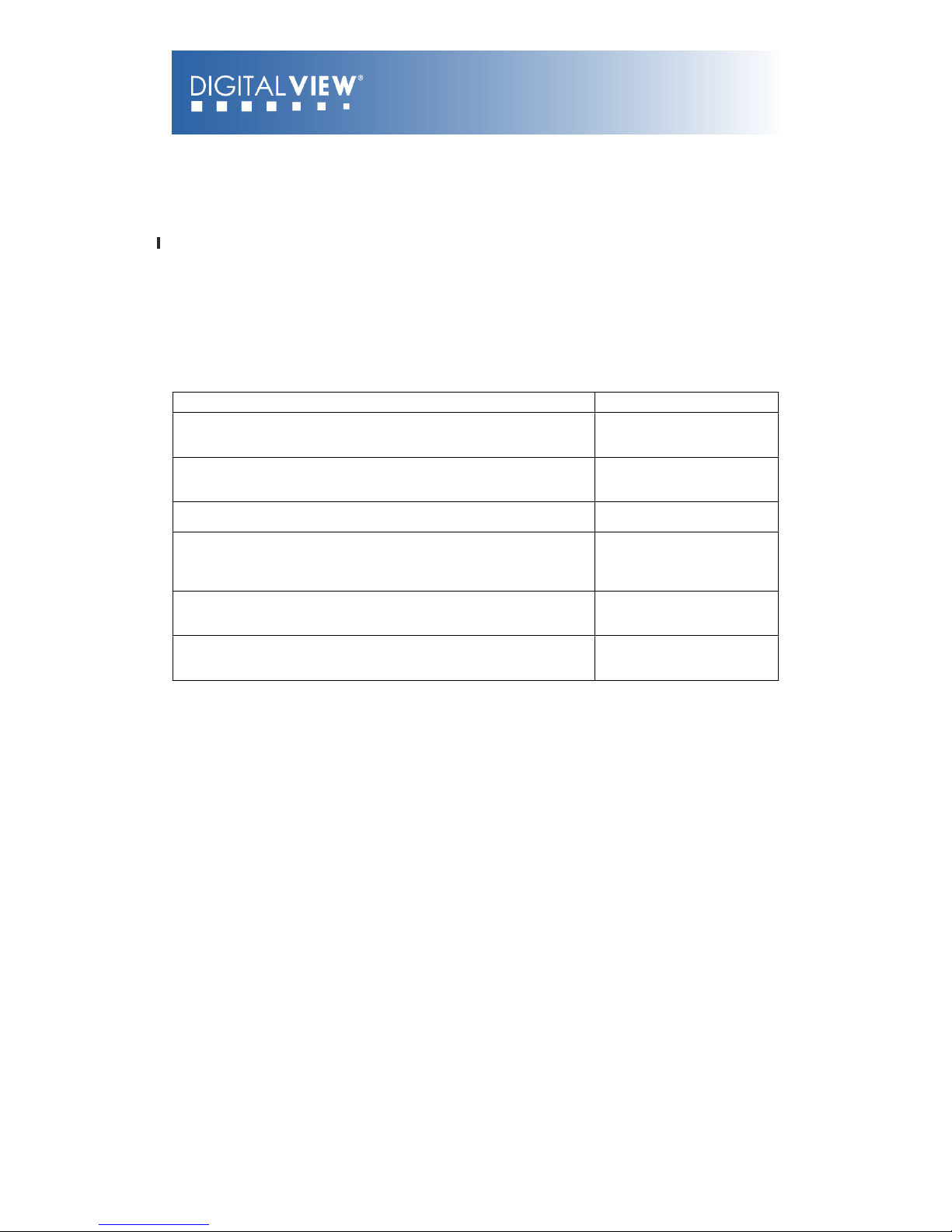
Buttons: The buttons on the AVX-1920 allow direct access to the On Screen
Display (OSD) for the various functions and settings.
Controls
Buttons
Menu
–
Turns OSD menu On or Off (it will auto time off)
–
Back to previous OSD menu page
Menu button
Select down
–
Moves the selector to the next function (down)
SEL DN
Select up
–
Moves the selector to the previous function (up)
SEL UP
+
–
Increase the OSD parameter values
–
Go into the sub-menu page from the top
–
Confirm to select the OSD function
+
-
–
Decrease the OSD parameter values
–
Go into the sub-menu page from the bottom
-
Reset to Factory Defaults
Press and hold SEL DN
button, then power on the
controller
© Digital View Ltd 2009
www.digitalview.com
Page 6 of 33
Page 7

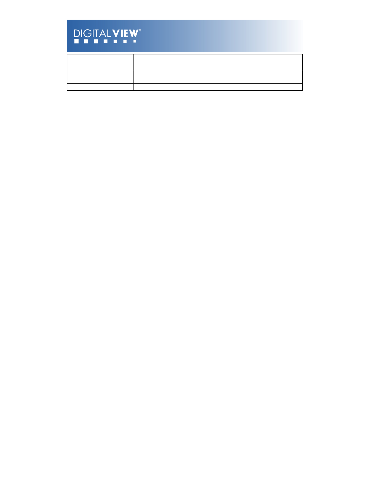
IR Remote Control: The Digital View IR remote control for the AVX-1920 offers
an alternative way to access the On Screen Display (OSD) for the various
functions and settings.
IR control definition
BUTTON
FUNCTION
SOFT POWER BUTTON
Soft power ON/OFF button.
AV/TV BUTTON
Use to loop to the next the input source. (ARGB/Composite/S-Video/Component/..)
SEL UP ( ) / SEL DN ( )
Use this button to direct control the hotkey function. Press the “SEL UP” button to
increase the pre-set hotkey parameter value and the “SEL DN” button to decrease
the pre-set hotkey parameter value. In OSD menu, pressing this button to select the
items.
+ / - BUTTON
Use this button to direct control the hotkey function. Press the “+” button to increase
the pre-set hotkey parameter value and the “-” button to decrease the pre-set
hotkey parameter value. In OSD menu, pressing this button to adjust the settings.
PIP BUTTON
Use to display the PIP (picture in picture) window on screen.
OSD BACK BUTTON
Use to display the OSD menu and go to the previous OSD screen.
OSD NEXT BUTTON
Use to display the OSD menu and go to the next OSD screen.
© Digital View Ltd 2009
www.digitalview.com
Page 7 of 33
Page 8
STOP (RGB) BUTTON
In input source selection mode, pressing this button to select ARGB source.
PLAY (YCrCb) BUTTON
In input source selection mode, pressing this button to select Component source.
TRACK (S-Vid) BUTTON
In input source selection mode, pressing this button to select S-Video source.
TRACK (Comp) BUTTON
In input source selection mode, pressing this button to select Composite source.
FREEZE BUTTON
Use this button to freeze and release the picture on your screen.
OSD Functions: The following shows the various functions and settings available
through the OSD.
© Digital View Ltd 2009
www.digitalview.com
Page 8 of 33
Page 9
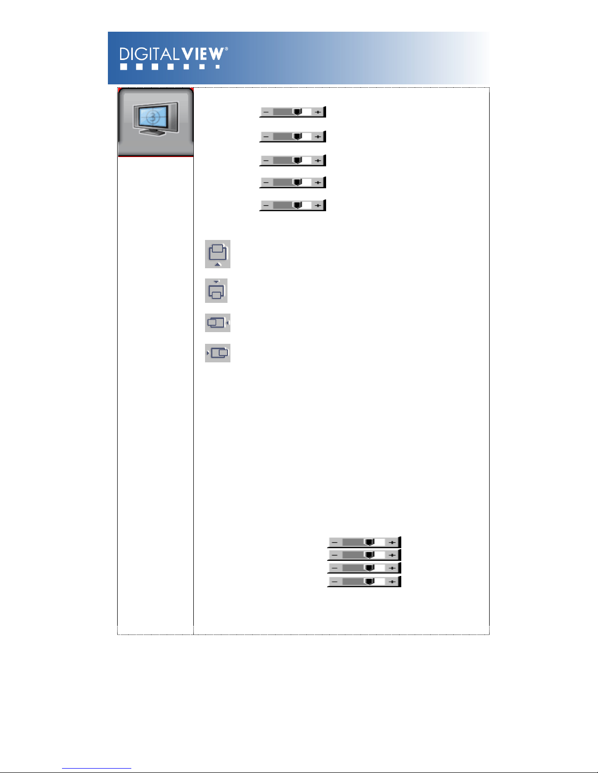
Picture:
Brightness Increase/decrease panel brightness level,
total: 100 steps
Contrast Increase/decrease panel contrast level,
total: 100 steps
Saturation Increase/decrease saturation, total: 100
steps
Hue ** Increase/decrease Hue level, total: 100
steps
Sharpness* Increase/decrease sharpness, total: 30
steps
Position##
Aspect / Size !
- Fill Screen : Enable full screen expansion for lower resolution Image
- Fill to Aspect Ratio: Enable fill screen expansion for lower resolution
image according to aspect ratio
- 4 : 3 : scaling format in 4:3
- 16 : 9 : scaling format in 16:9
- 16 : 10 : scaling format in 16:10
- 2.35 : 1 : scaling format in 2.35:1
- 2 : 1 : scaling format in 2:1
- 1 : 1 : Display the exact image resolution on the screen without
image expansion.
- Custom Sizing
*
:
- Overscan
- Normal
- Custom/Underscan !
H Size
H Pan
V Size
V Pan
* : DISPLAY IN VIDEO MODE ONLY
** : FUNCTION IN ARGB/ DVI / VIDEO NTSC MODE ONLY
## : FUNCTION IN ARGB MODE ONLY
© Digital View Ltd 2009
www.digitalview.com
Page 9 of 33
Page 10
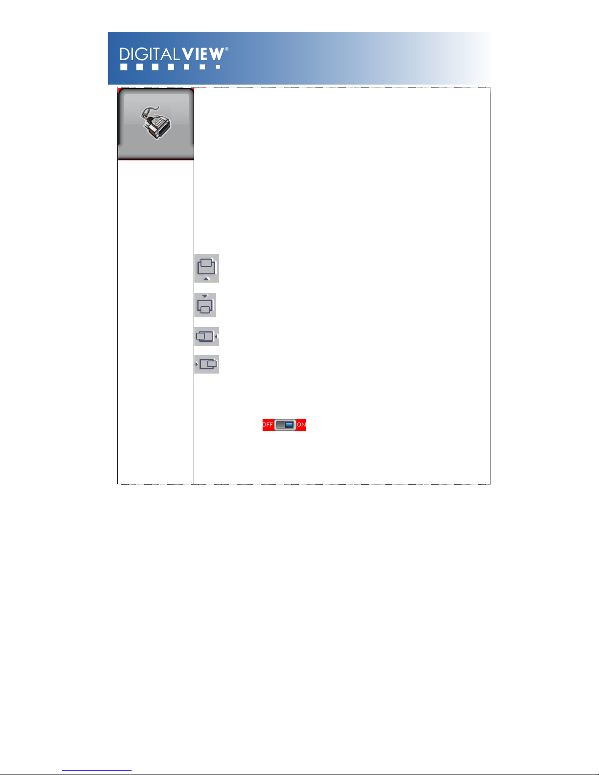
Source: Select the input video signal
Main Port Change !
VGA
#
DVI
HDMI
Composite 1
S-Video 1
Component 1
PIP Port change!
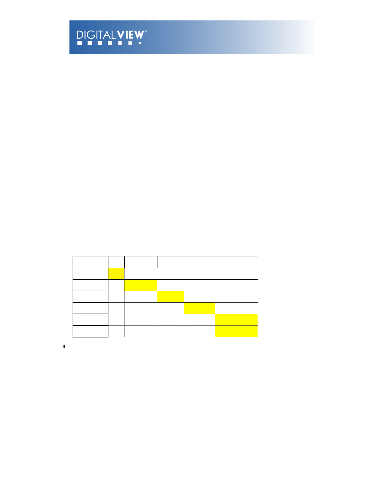
PIP Off / VGA / Composite 1 / S-Video 1 / Component 1 / DVI / HDMI
PIP Size!: Off / PIP Size 1~18 / Size by Size / Size by Size Tall
The PIP capability on display input sources refer to Appendix VII – PIP mix
table
PIP Position:
PIP Transparency: 6.25% ~ 100%
PIP Swap: Swap between the main window and PIP window
PIP Auto Turn off: : OFF / ON
ON: When PIP is no signal input after 30
seconds, the PIP window will turn
off automatically.
OFF: PIP window keeps on
© Digital View Ltd 2009
www.digitalview.com
Page 10 of 33
Page 11
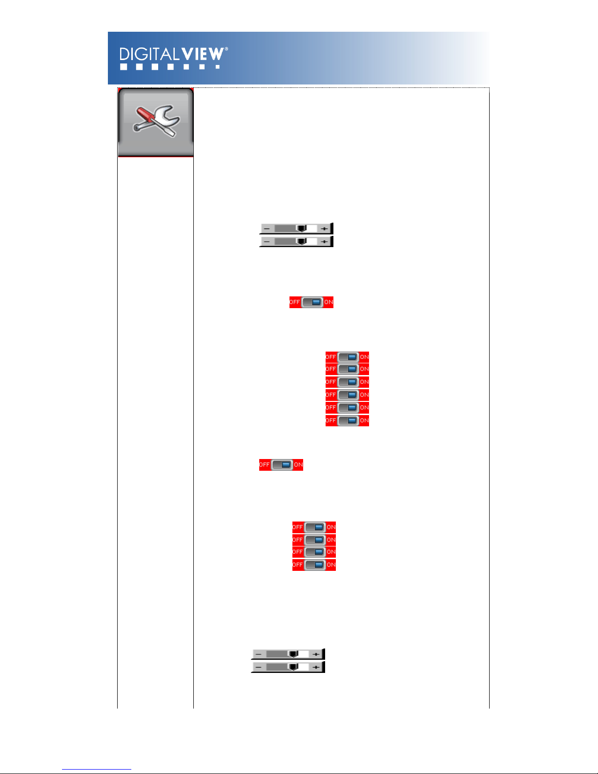
Utilities:
Setup !
Auto Picture Setup#: Auto adjust the image position, phase and
size
Auto Color Gain##: Auto Color Calibration (See appendix IV)
Wide Screen Mode detection# !: Recognize the wide screen mode coming
from ARGB port
- Off
- 1280x768
- 1360x768
- 1366x768
Manual Clock#: Adjust the image horizontal size
Manual Phase#: Fine tune the data sampling position
(adjust image quality)
Auto Source Seek:
- Auto: : OFF / ON
ON – Auto source select always enable
OFF – Disable auto source select function
- Setup!Selection for the corresponding input sources
detection
VGA
DVI
HDMI
Composite 1
S-Video 1
Component 1
The corresponding input port name display on OSD menu will
disappear once setting “OFF”.
Auto Power: OFF / ON
ON – Enable soft power off function if absence of input
signals
OFF – Disable soft power function
De-interlacing Mode* !
AFM : Auto Film Mode
TNR : Temporal Noise Reduction
MADI : Motion Adaptive De-interlacing
DCDi : Directional Correlation Deinterlacing
[See Appendix III for AFM, TNR, MADI, DCDi function
description]
Video Standard (SD)*: Auto / NTSC / NTSC 4.43 / PAL / PAL M / SECAM
Gamma: 0.6 / 0.7/ 0.8 / 0.9 / 1.0 / 1.1 / 1.2 / 1.3 / 1.4 / 1.5 / 1.6 / 1.8 /
1.9 / 2 / 2.1 / 2.2 / 2.3 / 2.4 / 2.5 / 2.6 / User Setting
OSD !
OSD position:
H POS : Move the OSD menu image horizontally
V POS : Move the OSD menu image vertically
OSD Timeout (sec): ON – 60: Adjust the OSD menu timeout period in a
step of 5
seconds (max 60 seconds)
© Digital View Ltd 2009
www.digitalview.com
Page 11 of 33
Page 12

Firmware : E0.17.X1
RS-232 Control: The AVX-1920 can be controlled through the RS-232 port using
the commands as summarized in Appendix II below. This provides comprehensive
access to the functions and settings as provided by the OSD commands.
Network Control: The AVX-1920 provides two choices for control over a
network:
Browser based: With the default network port firmware the AVX-1920
network connection includes a web server and a default suite of web pages
providing access to features and settings. Suitably qualified developers
can customize these web pages.
Direct control: The RS-232 command set (Appendix II) can be accessed
over the network. This requires either an RS-232 program with virtual
RS-232 port or a suitably written application. It will also require a change
to the AVX-1920 network port firmware.
© Digital View Ltd 2009
www.digitalview.com
Page 12 of 33
Page 13
APPENDIX I – SIGNAL SUPPORT MODE TABLE
ARGB (P1) PORT :
Mode
Resolution
Clk
[MHz]
Horizontal
freq [KHz]
Vertical
freq [Hz]
Sync Mode
T_70
720x400
70Hz
28.322
31.469
70.087
Digital Separate Sync
T_70
720x400
70Hz
28.322
31.469
70.087
Sync On Green
V_60
640x480
60Hz
25.175
31.469
59.940
Digital Separate Sync
V_60
640x480
60Hz
25.175
31.469
59.940
Sync On Green
V_60
640x480
60Hz
25.175
31.469
59.940
Composite Sync
V_72
640x480
72Hz
31.500
37.861
72.809
Digital Separate Sync
V_72
640x480
72Hz
31.500
37.861
72.809
Sync On Green
V_72
640x480
72Hz
31.500
37.861
72.809
Composite Sync
V_75
640x480
75Hz
31.500
37.500
75.000
Digital Separate Sync
V_75
640x480
75Hz
31.500
37.500
75.000
Sync On Green
V_75
640x480
75Hz
31.500
37.500
75.000
Composite Sync
SV_56
800x600
56Hz
36.000
35.156
56.250
Digital Separate Sync
SV_56
800x600
56Hz
36.000
35.156
56.250
Sync On Green
SV_56
800x600
56Hz
36.000
35.156
56.250
Composite Sync
SV_60
800x600
60Hz
40.000
37.879
60.317
Digital Separate Sync
SV_60
800x600
60Hz
40.000
37.879
60.317
Sync On Green
SV_60
800x600
60Hz
40.000
37.879
60.317
Composite Sync
SV_72
800x600
72Hz
50.000
48.077
72.188
Digital Separate Sync
SV_72
800x600
72Hz
50.000
48.077
72.188
Sync On Green
SV_72
800x600
72Hz
50.000
48.077
72.188
Composite Sync
SV_75
800x600
75Hz
49.500
46.875
75.000
Digital Separate Sync
SV_75
800x600
75Hz
49.500
46.875
75.000
Sync On Green
© Digital View Ltd 2009
www.digitalview.com
Page 13 of 33
Page 14
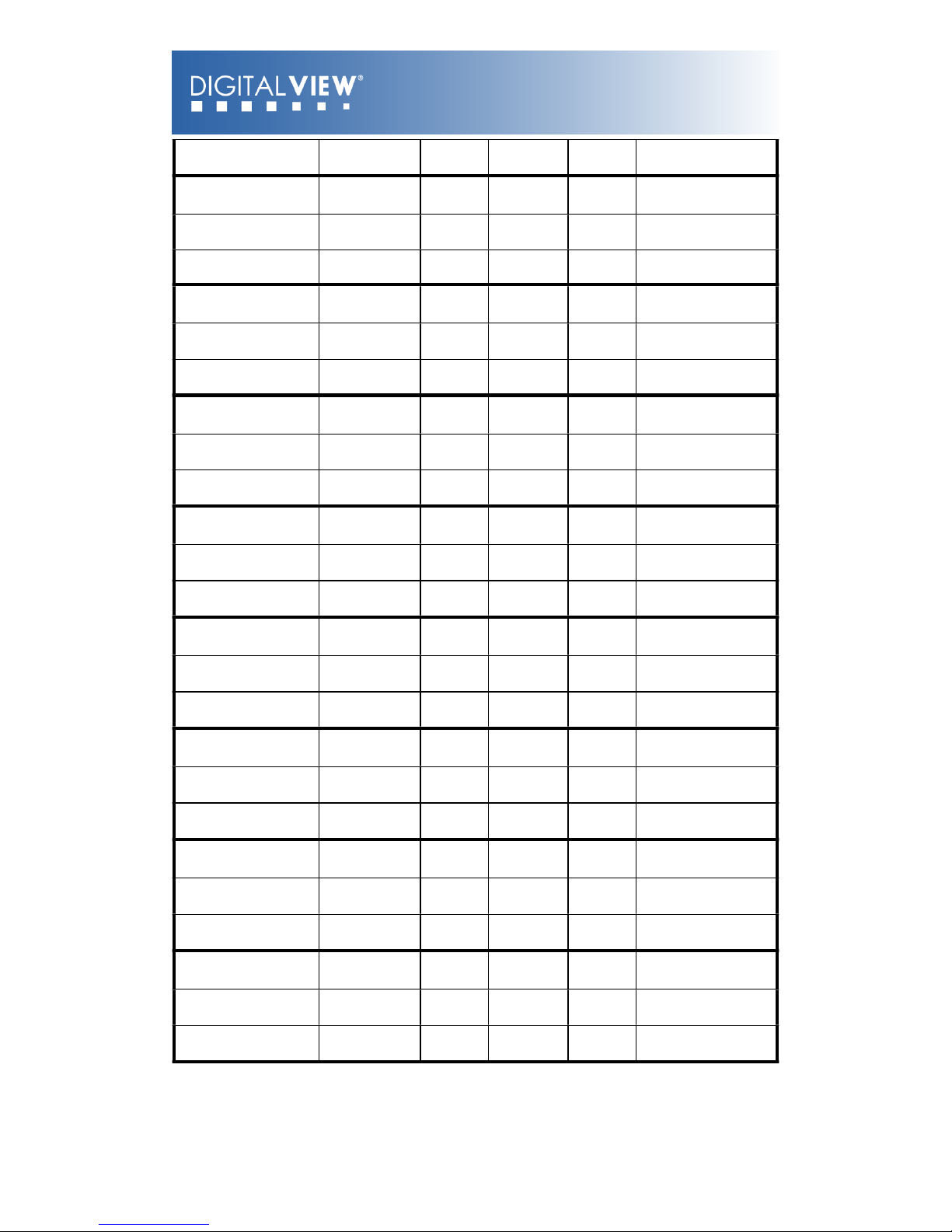
SV_75
800x600
75Hz
49.500
46.875
75.000
Composite Sync
X_60
1024x768
60Hz
65.000
48.363
60.004
Digital Separate Sync
X_60
1024x768
60Hz
65.000
48.363
60.004
Sync On Green
X_60
1024x768
60Hz
65.000
48.363
60.004
Composite Sync
X_70
1024x768
70Hz
75.000
56.476
70.069
Digital Separate Sync
X_70
1024x768
70Hz
75.000
56.476
70.069
Sync On Green
X_70
1024x768
70Hz
75.000
56.476
70.069
Composite Sync
X_75
1024x768
75Hz
78.750
60.023
75.029
Digital Separate Sync
X_75
1024x768
75Hz
78.750
60.023
75.029
Sync On Green
X_75
1024x768
75Hz
78.750
60.023
75.029
Composite Sync
SX_60
1280x1024
60Hz
108
63.81
60.020
Digital Separate Sync
SX_60
1280x1024
60Hz
108
63.81
60.020
Sync On Green
SX_60
1280x1024
60Hz
108
63.81
60.020
Composite Sync
SX_75
1280x1024
75Hz
135
79.976
75
Digital Separate Sync
SX_75
1280x1024
75Hz
135
79.97675Sync On Green
SX_75
1280x1024
75Hz
135
79.97675Composite Sync
UX_60
1600x1200
60Hz
162
75.000
60
Digital Separate Sync
UX_60
1600x1200
60Hz
162
75.00060Sync On Green
UX_60
1600x1200
60Hz
162
75.00060Composite Sync
WUX_60
1920x1080
60Hz
172.8
67.5
60
Digital Separate Sync
WUX_60
1920x1080
60Hz
172.8
67.560Sync On Green
WUX_60
1920x1080
60Hz
172.8
67.560Composite Sync
WUX_60
1920x1200
60Hz
193.2
74.5
60
Digital Separate Sync
WUX_60
1920x1200
60Hz
193.2
74.560Sync On Green
WUX_60
1920x1200
60Hz
193.2
74.560Composite Sync
COMPOSITE, S-VIDEO & COMPONENT VIDEO INPUT PORT :
© Digital View Ltd 2009
www.digitalview.com
Page 14 of 33
Page 15
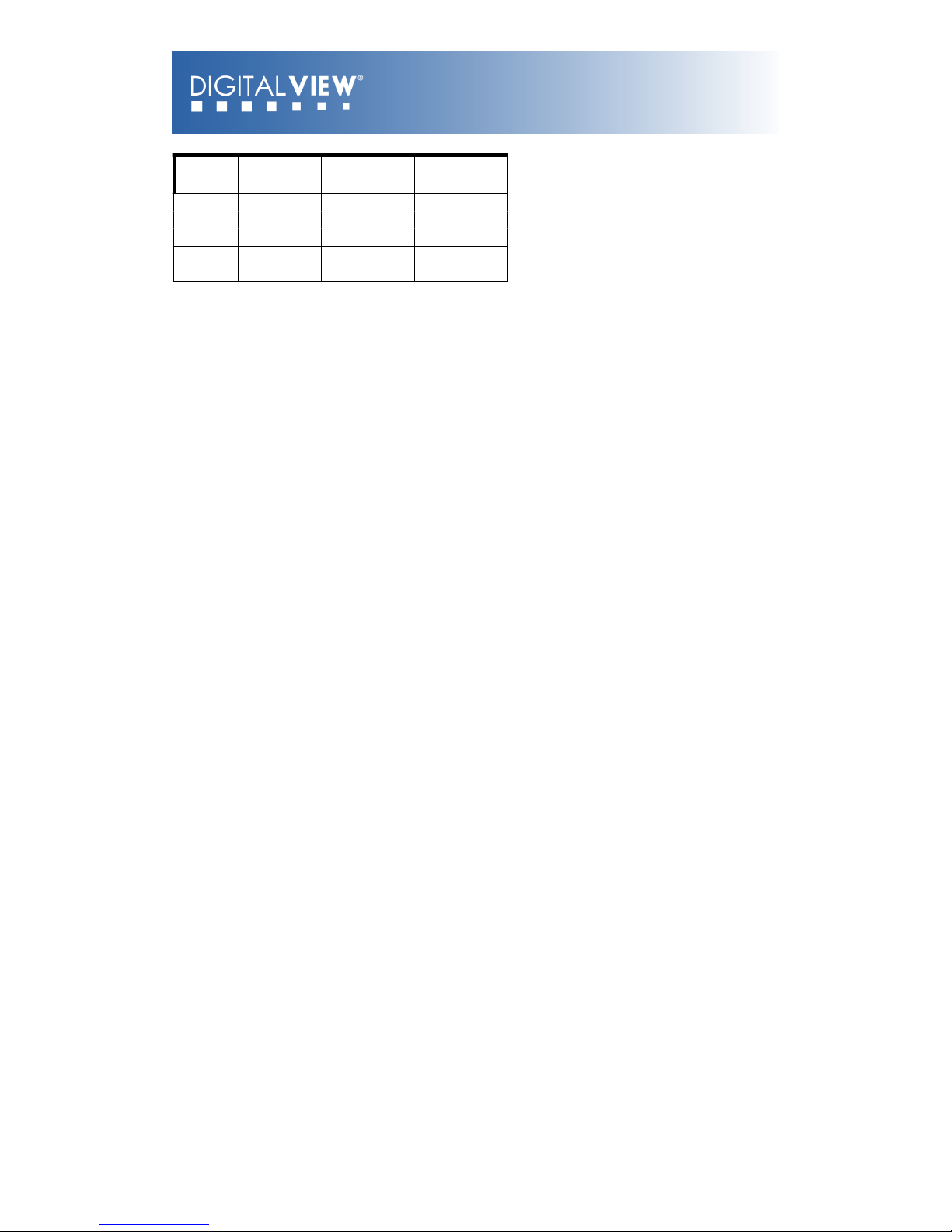
System
Resolution
Horizontal freq
[KHz]
Vertical freq
[Hz]
NTSC
720x480i
15.7
60
NTSC 4.43
720x480i
15.7
60
PAL
720x576i
15.6
50
PAL M
720x576i
15.6
50
SECAM
720x576i
15.6
50
© Digital View Ltd 2009
www.digitalview.com
Page 15 of 33
Page 16
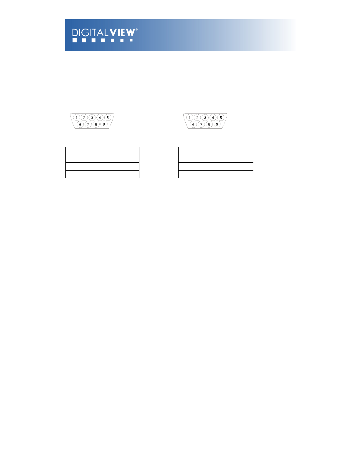
Appendix II – RS-232 control protocols
RS-232 Serial control (Baud rate 2400, 8 bits, 1 stop bit and no parity)
Physical connection:
AVX-1920 side Computer side
Connector interface: Serial Connector interface: Serial
Mating connector: DB9 Male Mating connector: DB9 Male
PIN#
Description
PIN#
Description
2
RS-232 Rx Data
2
RS-232 Rx Data
3
RS-232 Tx Data
3
RS-232 Tx Data
5
Ground
5
Ground
Software connection:
The OSD function can be controlled through sending the RS-232 protocol.
The RS-232 program can be custom-made to fit for application or it can be used the serial control program, like
Accessport, Telix or Serial Utility program developed by DigitalView. Please contact your local support for information.
© Digital View Ltd 2009
www.digitalview.com
Page 16 of 33
Page 17
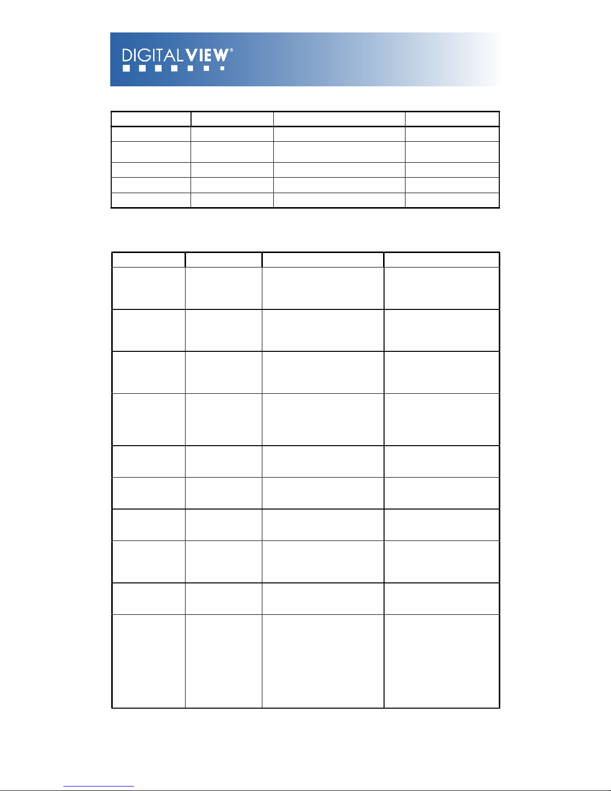
1. Commands to implement switch mount control buttons
Function
Command
Description
Remark
Menu button
0xf7
Menu button pressed
Button equivalent
Select-down
button
0xfa
Select-down button pressed
Button equivalent
Select-up button
0xfb
Select-up button pressed
Button equivalent
Right/+ button
0xfc
Right/+ button pressed
Button equivalent
Left/- button
0xfd
Left/- button pressed
Button equivalent
2. Parameter setting - immediate, relative, reset and query
Function
Command
Description
Acknowledge (if enabled)
Brightness
control
0x81,
nn | “+” | “-” |
“r” | “R” |
“?”
Set brightness =
value/increment/decrement
Reset
Query
Brightness.
Range : “4””E”-“B””2”
Default : “8””0”
Contrast control all channels
0x82, “a” | “A”,
nn | “+” | “-” |
“r” | “R” |
“?”
Set all contrast =
value/increment/decrement
Reset
Query
Contrast
Range : “1””C”-“E””4”
Default : “8””0”
Saturation
control
0x83,
nn | “+” | “-” |
“r” | “R” |
“?”
Set saturation =
value/increment/decrement
Reset
Query
Range : “0””1”-“F””F”
Default : “8””0”
Hue control
0x84,
nn | “+” | “-” |
“r” | “R” |
“?”
Set hue =
value/increment/decrement
Reset
Query
NTSC tint (In NTSC mode
only)
Range : “5””3”-“9””F”
Default : “7””9”
Phase (tuning)
control
0x85,
nn | “+” | “-” |
“?”
Set dot clock phase =
value/increment/decrement
Query
Dot clock phase.
(In PC mode only)
Image H position
0x86,
nnnn | “+” | “-” |
“?”
Set img_hpos =
value/increment/decrement
Query
Image horizontal position.
(In PC mode only)
Image V position
0x87,
nnnn | “+” | “-” |
“?”
Set img_vpos =
value/increment/decrement
Query
Image vertical position.
(In PC mode only)
Sharpness
0x8a,
nn | “+” | “-” |
“r” | “R” |
“?”
Set sharpness =
value/increment/decrement
Reset
Query
Sharpness.
(Video Mode Source only)
Range : “F””4”-“0””C”
Default : “0””0”
Frequency
0x8b,
nnnn | “+” | “-“ |
“?”
Set frequency =
Value/increment/decrement
Query
Graphic mode H active
size (in pixels)
Scaling Mode
0x8c,
“0” | “1” | “2” | “3”
| “9” | “A” |
“B” | “C” | “D” |
“r” | “R” |
“?”
Set graphic image scaling
mode =
value
Reset
Query
Image expansion on/off.
“0” – 1:1
“1” – fill screen
“2” – fill to aspect ratio
“9” – 4:3
“A” – 16:9
“B” – 16:10
“C” – 2.35:1
“D” – 2:1
© Digital View Ltd 2009
www.digitalview.com
Page 17 of 33
Page 18
OSD H position
0x90,
nnn | “+” | “-” |
“r” | “R” |
“?”
Set osd_hpos =
value/increment/decrement
Reset
Query
OSD horizontal position.
Range : “0””0”-“F””F”
Default : “8””0”
OSD V position
0x91,
nnn | “+” | “-” |
“r” | “R” |
“?”
Set osd_vpos =
value/increment/decrement
Reset
Query
OSD vertical position.
Range : “0””0”-“F””F”
Default : “8””0”
OSD
Transparency
0x92,
n | “+” | “-” |
“r” | “R” |
“?”
Set OSD transparency =
value/increment/decrement
Reset
Query
OSD transparency.
“0” – ON
“1” - OFF
OSD menu
timeout
0x93,
nn | “+” | “-” |
“r” | “R” |
“?”
Select menu timeout =
value/increment/decrement
Reset
Query
OSD menu timeout value.
“0””0” – Continuous.
value – Round up to
nearest available step.
if value > max available
step, set it to the max
available step.
Range : “0””5”-“3””C”
Default : “0””A”
Select OSD
language
0x95,
n |
“r” | “R” |
“?”
Select language =
English, Chinese,…
Reset
Query
“0” – English.
“2” - French
“3” – Spanish
“6” - German
“8” – Chinese
Input main select
0x98,
nn | “+” | “-” |
“r” | “R” |
“?”
Select input main =
PC or VIDEO or next
available
Reset
Query
Main selected.
“0x41,0x31” ARGB
“0x42,0x31” Composite 1
“0x43,0x31” S-video 1
“0x44,0x31” Component 1
“0x46,0x31” DVI
“0x48,0x31” HDMI
Auto Source
Seek
0x99,
nn ,
“0” | “1” |
“?” |
”o”
Set Auto source enable = *1
Source
Disable/ Enable
Query
Valid Source query
“nn” =
“0x41,0x31”- ARGB
“0x42,0x31”- Composite 1
“0x43,0x31”- S-video 1
“0x44,0x31”- Component 1
“0x46,0x31”- DVI
“0x48,0x31” HDMI
Source Layout
0x9a,
n |
“r” | “R” |
“?”
Select source layout =
Single, PIP, PBP, PBPT
Reset,
Query
Query:
“0”- Single
“1”- Picture in Picture (PIP)
“2”- Picture by Picture
(PBP)
“3”- Picture by Picture Tall
(PBPT)
© Digital View Ltd 2009
www.digitalview.com
Page 18 of 33
Page 19
Video System
(Composite, Svideo and
Component
Only)
0x9b,
“0” | “1” | “2” | “3”
|
“r” | “R” |
“S” | “s”|
“?”
Set video system =
Auto/NTSC/PAL/SECAM
Reset
Video State Query
Query
Query
“0” – Auto.
“1” – NTSC_M_358
“2” – PAL_N_443
“3” – SECAM
“4” – NTSC_M_443
“5” - PAL_M_358
“7” – PAL_M_443
“9” – PAL_N_358
Video State Query
“0” – No video.
“1” – NTSC
“2” – PAL
“3” – SECAM
“4” – NTSC 443
“5” – PAL M 358
GAMMA value
select
0x9d,
n |
“r” | “R”
“?”
Select GAMMA value =
Valu e
Reset
Query
GAMMA value:
“0” – 1.0, “1” – 1.6
“2” – 2.2, “3” – User
Defined
“4” – 1.7, “5” – 1.8,
“6” – 1.9, “7” – 2.0,
“8” – 2.1, “9” – 2.3,
“A” – 2.4, “B” – 2.5,
“C” – 2.6,
“D” – 0.6, “E” – 0.7,
“F” – 0.8, “G” – 0.9,
“H” – 1.1, “I” – 1.2,
“J” – 1.3, “K” – 1.4,
“L” – 1.5
Auto power off
0x9f,
“0” | “1” |
“r” | “R” |
“?”
Set power down option =
On/Off
Reset
Query
“0” – Off.
“1” – On.
Hotkey 1
0xa0, “1”,
n |
“r” | “R” |
“?”
Set Hotkey 1=
Value
Reset
Query
“2” – brightness.
“3” – contrast.
“4” – colour.
“5” – input source.
“7” – zoom
“8” – freeze
“9” – PIP
“B” – No function
“D” – PIP Swap
“E” – Aspect Ratio
“G” – Hue
“I” – Auto Picture Setup
Hotkey 2
0xa0, “2”,
n |
“r” | “R” |
“?”
Set Hotkey 2 =
value
Reset
Query
“2” – brightness.
“3” – contrast.
“4” – colour.
“5” – input source.
“7” – zoom
“8” – freeze
“9” – PIP
“B” – No function
“D” – PIP Swap
“E” – Aspect Ratio
“G” – Hue
“I” – Auto Picture Setup
© Digital View Ltd 2009
www.digitalview.com
Page 19 of 33
Page 20
Runtime counter
0xa1,
nnnnn |
“r” | “R” |
“?”
runtime counter value =
nnnnn (* 0.5 hour)
Reset
Query
Runtime = nnnnn.
PIP brightness
control
0xa2,
nn | “+” | “-” |
“r” | “R” |
“?”
Set PIP window brightness =
value/increment/decrement
Reset
Query
PIP window brightness.
Range : “4””E”-“B””2”
Default : “8””0”
PIP contrast
control
0xa3,
nn | “+” | “-” |
“r” | “R” |
“?”
Set PIP window contrast =
value/increment/decrement
Reset
Query
PIP window contrast.
Range : “1””C”-“E””4”
Default : “8””0”
PIP H position
0xa4,
nnn | “+” | “-” |
“r” | “R” |
“?”
Set PIP_hpos =
value/increment/decrement
Reset
Query
PIP window horizontal
position.
Range : “0””0””0”-“0””6””4”
Default : “0””5””5”
PIP V position
0xa5,
nnn | “+” | “-” |
“r” | “R” |
“?”
Set PIP_vpos =
value/increment/decrement
Reset
Query
PIP window vertical
position.
Range : “0””0””0”-“0””6””4”
Default : “0””1””4”
PIP window size
select
0xa6,
nn |
“r” | “R” |
“?”
Select PIP window size =
PIP window size value
Reset
Query
Main selected.
PIP off if “nn” = “0””0”.
“0””0”~”1””2”
“0””0” ~ “1””2”
“1””9” : Size by Size
“1””A” : Size by Size Tall
PIP source
select
0xa7,
n |
“r” | “R” |
“?”
Select input main =
Video source value
Reset
Query
Main selected.
0x41, 0x31 : ARGB
0x42, 0x31 : Composite
0x43, 0x31 : S-video
0x44, 0x31 : Component
0x46, 0x31 : DVI
0x48, 0x31 : HDMI
Zoom level
0xa8,
nnnn | “+” | “-” |
“r” | “R” |
“?”
Set Zoom level =
value/increment/decrement
Reset
Query
Zoom level.
Min : 0x30 0x30 0x30 0x30
(Default)
Max : 0x30 0x30 0x41
0x33
Zoom H position
0xa9,
nnnn | “+” | “-” |
“r” | “R” |
“?”
Set Zoom_hpos =
value/increment/decrement
Reset
Query
Zoom window horizontal
position.
Default : 0x30 0x30 0x30
0x30
The min and max values
will change depends on
input resolution.
Zoom V position
0xaa,
nnnn | “+” | “-” |
“r” | “R” |
“?”
Set Zoom_vpos =
value/increment/decrement
Reset
Query
Zoom window vertical
position.
Default : 0x30 0x30 0x30
0x30
The min and max values
will change depends on
input resolution.
© Digital View Ltd 2009
www.digitalview.com
Page 20 of 33
Page 21
Horizontal Size
0xad,
nnn | “+” | “-” |
“r” | “R” |
“?”
Set horizontal size for
Aspect Size =
value/increment/decrement
Reset
Query
Scalar horizontal stretch
PAL(576i) / NTSC (480i) :
Min : 0x30 0x30 0x30
(Default)
Max : 0x30 0x46 0x30
Vertical Size
0xb0,
nnn | “+” | “-” |
“r” | “R” |
“?”
Set Vertical Size for
Aspect Size =
value/increment/decrement
Reset
Query
Scalar vertical stretch.
PAL(576i) / NTSC (480i) :
Min : 0x30 0x30 0x30
(Default)
Max : 0x30 0x46 0x30
Horizontal Pan
0xb1,
nnn | “+” | “-” |
“r” | “R” |
“?”
Set horizontal pan position
for Aspect Size =
value/increment/decrement
Reset
Query
Scalar horizontal pan
position
PAL(576i) / NTSC (480i) :
Assume max H-Size & max
V-size :
Min : 0x46 0x38 0x38
Max : 0x30 0x37 0x38
Default : 0x30 0x30 0x30
The min and max values
will change depends on
different value of H-Size, VSize and input resolution.
Vertical Pan
0xb2,
nnn | “+” | “-” |
“r” | “R” |
“?”
Set Vertical pan position
for Aspect Size =
value/increment/decrement
Reset
Query
Scalar vertical pan position
PAL(576i) / NTSC (480i) :
Assume max H-Size & max
V-size :
Min : 0x46 0x38 0x38
Max : 0x30 0x37 0x38
Default : 0x30 0x30 0x30
The min and max values
will change depends on
different value of H-Size, VSize and input resolution.
Colour
temperature
select
0xb3,
n |
“r” | “R” |
“?”
Select colour temperature =
value
Reset
Query
Main selected.
“0” – 9300K.
“1” – 8000K.
“2” – 6500K.
“3” – 5000K
“4” - User
Red level for
selected colour
temperature
0xb4,
nn | “+” | “-” |
“r” | “R” |
“?”
Set the level of the red
channel for the selected
colour temp. =
value/increment/decrement
Reset
Query
Red level for selected
colour temperature.
Range : “9””C”-“F””F”
Default : “E””C”
Green level for
selected colour
temperature
0xb5,
nn | “+” | “-” |
“r” | “R” |
“?”
Set the level of the green
channel for the selected
colour temp. =
value/increment/decrement
Reset
Query
Green level for selected
colour temperature.
Range : “9””C”-“F””F”
Default : “E””C”
© Digital View Ltd 2009
www.digitalview.com
Page 21 of 33
Page 22
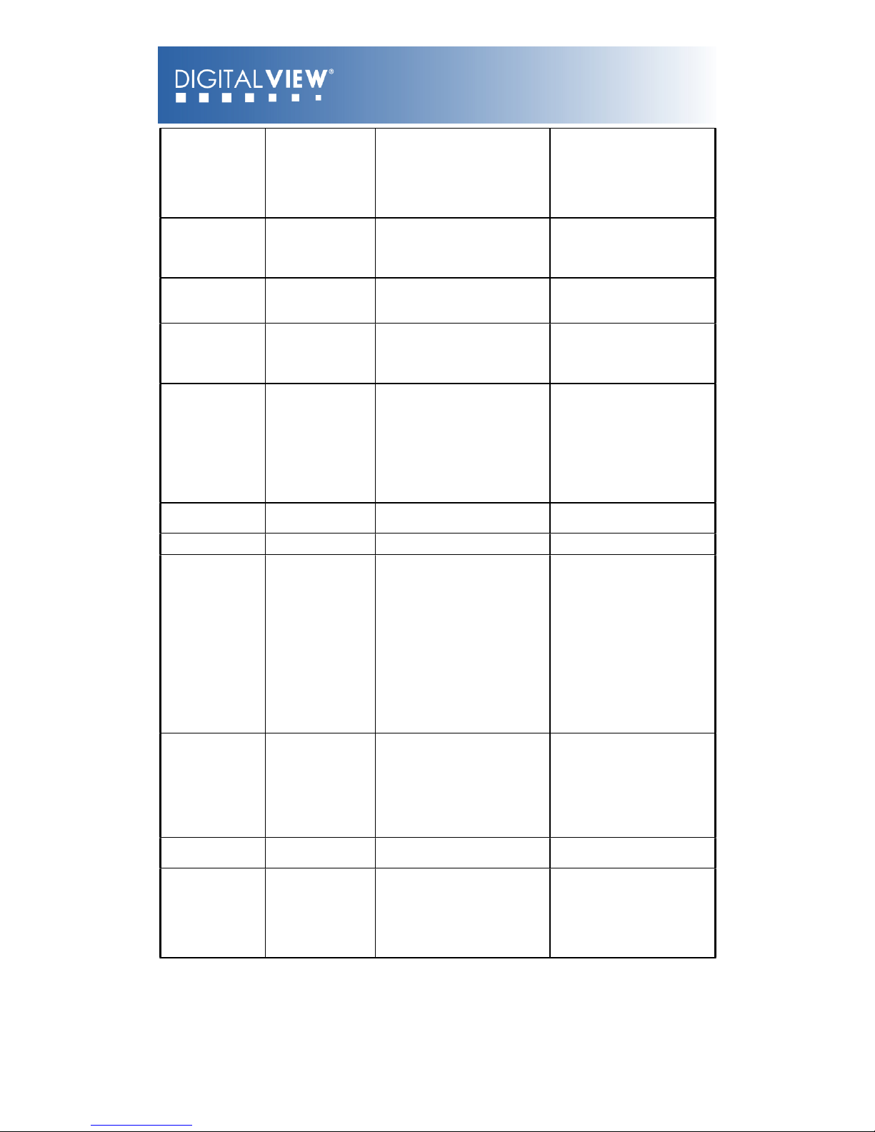
Blue level for
selected colour
temperature
0xb6,
nn | “+” | “-” |
“r” | “R” |
“?”
Set the level of the blue
channel for the selected
colour temp. =
value/increment/decrement
Reset
Query
Blue level for selected
colour temperature.
Range : “9””C”-“F””F”
Default : “E””C”
Graphic
horizontal
resolution
enquiry
0xb7
Horizontal resolution (in
pixels) in 3 digit hex number
“nnn” = horizontal
resolution
Graphic vertical
resolution
enquiry
0xb8
Vertical resolution (in lines)
in 3 digit hex number
“nnn” = vertical resolution
Graphic
horizontal sync
frequency
enquiry
0xb9
Horizontal sync frequency (in
units of 100Hz) in 3 digit hex
number
“nnn” = horizontal
frequency
Graphic vertical
sync frequency
enquiry
0xba
Vertical sync frequency (in
units of Hz) in 3 digit hex
number and 1 char
“nnnn” = vertical frequency
nnn = 3 digit hex
c= “i” or “p”
interlace or Progressive
0xba added the interlace(i)
or Progressive(p)
feedback.
OSD status
enquiry
0xbb
Status of OSD
“0” – OSD turned off
“1” – OSD turned on
OSD turn off
0xbd
Turn off the OSD.
“1” – successful.
Set gamma data
for user defined
gamma curve
0xbf, mm, c, “?”
0xbf, “R” | “r”
0xbf, mm, c, nn
Query gamma data for color
c index mm ( c = 0 for color
Red,
c=1 for color Green,
c=2 for color Blue)
Set user gamma curve to
linear
Set gamma data for color c
index mm. (If c= 3, then
gamma data for red, green &
blue will be set at the same
time.)
“nn” = gamma data
“1”
“nn” = gamma data
Color
Monochrome
mode selection
(Output Channel
Select)
0xe2
“0” | “1” | “2” | “3” |
| “4” | “5” | “6” |
“R” | “r”|
”?”
Off/
Blue Only/
Red Only/
Green Only/
Blue Mono/
Red Mono/
Green Mono/
“0” – Off
“1” – Blue Only
“2” – Red Only
“3” – Green Only
“4” – Blue Mono
“5” – Red Mono
“6” – Green Mono
PIP Swap
0xe3
Swap Main and PIP source
"0" - Fail.
"1" - Successful.
Red Offset for
selected colour
temperature
0xe8,
nn | “+” | “-” |
“r” | “R” |
“?”
Set the Offset of the red
channel for the selected
colour temp. =
value/increment/decrement
Reset
Query
Red Offset for selected
colour temperature.
© Digital View Ltd 2009
www.digitalview.com
Page 22 of 33
Page 23
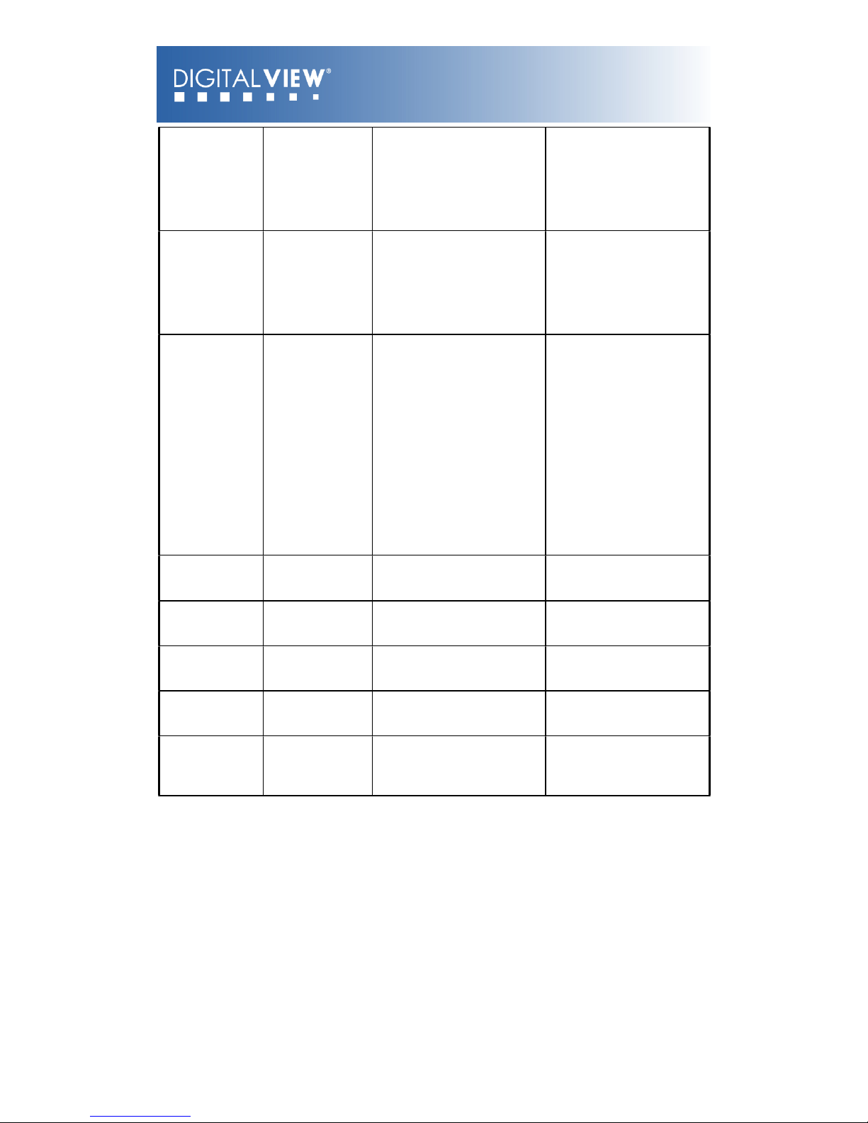
Green Offset for
selected colour
temperature
0xe9,
nn | “+” | “-” |
“r” | “R” |
“?”
Set the Offset of the green
channel for the selected
colour temp. =
value/increment/decrement
Reset
Query
Green Offset for selected
colour temperature.
Blue Offset for
selected colour
temperature
0xea,
nn | “+” | “-” |
“r” | “R” |
“?”
Set the Offset of the blue
channel for the selected
colour temp. =
value/increment/decrement
Reset
Query
Blue Offset for selected
colour temperature.
PIP Window
Transparency
0xed,
nn | “+” | “-” |
“R” | “r” |
“?”
Select PIP Transparency
Level
PIP Transparency value
Reset
Query
PIP Transparency
“0”F” = 6.25% “0”E” =
12.5%
“0”D” = 18.75% “0”C” =
25%
“0”B” = 31.25% “0”A” =
37.5%
“0”9” = 43.75% “0”8” = 50%
“0”7” = 56.25% “0”6” =
62.5%
“0”5” = 68.75% “0”4” = 75%
“0”3” = 81.25% “0”2” =
87.5%
“0”1” = 93.75% “0”0” =
100%.
PIP Window
Auto Off
“0xee”, “0x41”
“0” |”1”
“?”
Auto Off / Auto On
Query
“0”- Off
“1”- On
ScreenMarker
“0xee”, “0x42”
“0” |”1”
Screen Marker Off / Screen
Marker On
“0”- Off
“1”- On
CenterMarker
“0xee”, “0x43”
“0” |”1”
Center Marker Off / Center
Marker On
“0”- Off
“1”- On
AspectMarker
“0xee”, “0x44”
“0” |”1”
Preliminary
4:3 /16:9
“0”- 4:3
“1”- 16:9
Marker
Background
Transparency
“0xee”, “0x45”
“0” |”1” |”2” |”3”
Preliminary
0% /25%/50%/95%
“0”- 0%
“1”- 25%
“2”- 50%
“3”- 95%
© Digital View Ltd 2009
www.digitalview.com
Page 23 of 33
Page 24
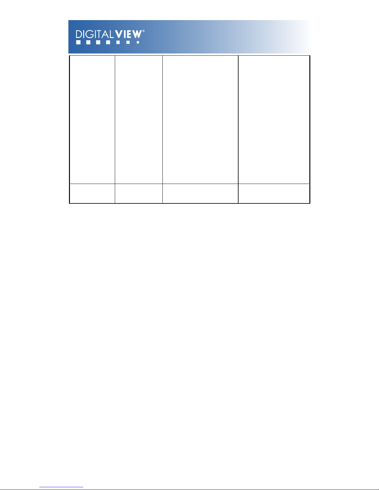
Safe Area
Marker
“0xee”, “0x46”
“0x53”~”0x63”
Preliminary
64%~98%
“36”, “33”- 98%
“36”, “32”- 96%
“36”, “31”- 94%
“36”, “30”- 92%
“35”, “46”- 90%
“35”, “45”- 88%
“35”, “44”- 86%
“35”, “43”- 84%
“35”, “42”- 83%
“35”, “41”- 81%
“35”, “39”- 79%
“35”, “38”- 77%
“35”, “37”- 76%
“35”, “36”- 74%
“35”, “35”- 72%
“35”, “34”- 71%
“35”, “33”- 69%
“35”, “32”- 67%
“35”, “31”- 66%
“35”, “30”- 64%
Custom Sizing
0xef,
“0” | “1” | “2”
”?”
Custom sizing selection :
Overscan / Normal / Custom
Query
“0” – Overscan
“1” – Custom/Underscan
“2” – Normal
© Digital View Ltd 2009
www.digitalview.com
Page 24 of 33
Page 25
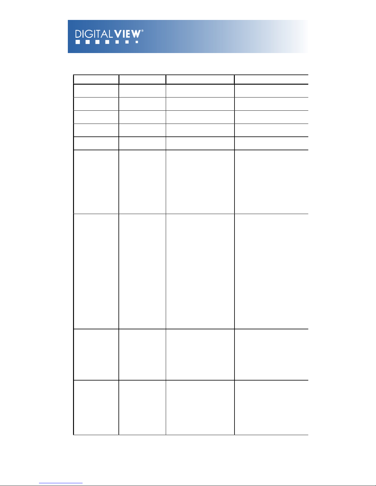
3. Other control
Function
Command
Description
Acknowledge (if enabled)
Select RS-232
acknowledge
0xc1, “0” | “1”
Disable/enable command
acknowledge.
“0” – acknowledge disabled.
“1” – acknowledge enabled.
Auto-setup
0xc3
Start auto-setup of current
vmode.
“0” – fail.
“1” – successful.
Command
availability
0xc4, n
Check whether a
command is available.
“0” – not available.
“1” – available.
Auto-calibration
0xc5
Start auto-calibration of
gain of the RGB amplifier.
“0” – fail.
“1” – successful.
Freeze frame
0xc6, “0” | “1”
Unfreeze / freeze frame
“0” – unfreeze.
“1” – freeze.
Soft Power On/
Off
0xc8,
“0” | “1” |
“?”
Soft power
off/on
query
“0” – Turn off the LCD power
and
backlight. Turn off
memory
controller, Power down
DVI
Power down ADC,
Power
down Fclk PLL
“1” – Turn on the unit
Query video
input status
0xc9
Query the status of the
primary & pip status
“nn,nn” = input status
“nn,xx” digit = primary status:
“0”,”0” : invalid
“A”,”1” ARGB
“B”,”1” Composite
“C”,”1” S-video
“D”,”1” Component
“F”,”1” DVI
“H” “1” HDMI
“xx,nn”= PIP input status:
“0”,”0”: invalid
“A”,”1” ARGB
“B”,”1” Composite
“C”,”1” S-video
“D”,”1” Component
“F”,”1” DVI
“H” “1” HDMI
Video deinterlace method
0xca,
“0” | “1”
“r” | “R”
“?”
De-interlace mode
Reset
Query
“3” ”1”- enable AFM
“3” ”0”- disable AFM
“4” ”1”- enable TNR
“4” ”0”- disable TNR
“5” ”1”- enable MADI
“5” ”0”- disable MADI
“7” ”1”- enable DCDi
“7” ”0”- disable DCDi
Query BIOS
version
0xcb, “0”
Read BIOS version
BIOS version “VV.YY.ZZ”
VV = V0 or E0,
V0 = Release version
E0 = Engineering Sample
YY= Version Number
ZZ= Customer Number
© Digital View Ltd 2009
www.digitalview.com
Page 25 of 33
Page 26
Reset parameter
0xce
Reset all parameters to
default value
“1” – successful.
Wide Screen
Mode Selection
0xd9,
“0” | “1”| “2”
“r” | “R”
“?”
Wide Screen Mode
Reset
Query
“0” – Normal Mode
“1” – 1280x768
“2” – 1366x768
“3” – 1360x768
ScreenMarker
“0xee”, “0x42”
“0” |”1”
Screen Marker Off /
Screen Marker On
“0”- Off
“1”- On
CenterMarker
“0xee”, “0x43”
“0” |”1”
Center Marker Off /
Center Marker On
“0”- Off
“1”- On
AspectMarker
“0xee”, “0x44”
“0” |”1”
Preliminary
4:3 /16:9
“0”- 4:3
“1”- 16:9
Marker
Background
Transparency
“0xee”, “0x45”
“0” |”1” |”2” |”3”
Preliminary
0% /25%/50%/95%
“0”- 0%
“1”- 25%
“2”- 50%
“3”- 95%
Safe Area Marker
“0xee”, “0x46”
“0x53”~”0x63”
Preliminary
64%~98%
“36”, “33”- 98%
“36”, “32”- 96%
“36”, “31”- 94%
“36”, “30”- 92%
“35”, “46”- 90%
“35”, “45”- 88%
“35”, “44”- 86%
“35”, “43”- 84%
“35”, “42”- 83%
“35”, “41”- 81%
“35”, “39”- 79%
“35”, “38”- 77%
“35”, “37”- 76%
“35”, “36”- 74%
“35”, “35”- 72%
“35”, “34”- 71%
“35”, “33”- 69%
“35”, “32”- 67%
“35”, “31”- 66%
“35”, “30”- 64%
© Digital View Ltd 2009
www.digitalview.com
Page 26 of 33
Page 27
The following commands for sending texts by using RS-232 command.
Function
Command
Description
Acknowledge (if enabled)
Send Line
0xF0,
|”S” |”LL”|”TEXT”|
“0x0A”
Return “1”
“S” = “0x53 or 0x73”
Send command
---------------------------------------
----
“LL” =
“0x30,0x31~0x30,0x34”
Line number (Rang 0~4
lines)
---------------------------------------
----
“Text”= ASCII code,
“0x20~0x7E”
Character( Rang 0~34 )
---------------------------------------
----
0x0A = End of line
“S” – Send Command
“LL” – Line Number
“Text” – Character
“0x0A” – End of Line
“1” - successful.
e.g Display “Send Text” message on screen:
RS232 Code:“0xF0 0x53 0x30 0x31 0x53 0x65 0x6E 0x64 0x20 0x54 0x65 0x78 0x74 0x0A”
Return Code: “0xF0 0x53 0x30 0x31 0x53 0x65 0x6E 0x64 0x20 0x54 0x65 0x78 0x74 0x0A
0x31”
Clear Line
0xF0,
|”C” |”LL”|
Return “nn”
“C” = “0x43 or 0x63”
Clear command
---------------------------------------
----
“LL” =
“0x30,0x31~0x30,0x34”
Line number (Rang 0~4
lines)
“C” – Clear command
“LL” – Line Number
“nn” – Return Line number
e.g. Clear Line 1
RS232 Code: “0xF0 0x43 0x30 0x31”
Return Code: “0xF0 0x43 0x30 0x31 0x30 0x31”
Text Window
Horizontal Position
0xF0,
|”H” |”ss”|
Return “nn”
“H” = “0x48 or 0x68”
-------------------------------------
-----“nn” =
“0x30,0x30~0x46,0x46”
“H” – Horizontal Position
command
“ss” – Set Horizontal
Position number
“nn” – Return Position
number
e.g. Set Text Window Horizontal Position
RS232 Code: “0xF0 0x48 0x30 0x31”
Return Code: “0xF0 0x48 0x30 0x31 0x30 0x31”
Text Window
Vertical Position
0xF0,
|”V” |”ss”|
Return “nn”
“V” = “0x56 or 0x76”
-------------------------------------
-----“nn” =
“0x30,0x30~0x46,0x46”
“V” – Vertical Position
command
“ss” – Set Vertical Position
number
“nn” – Return Position
number
e.g. Set Text Window Vertical Position
RS232 Code: “0xF0 0x56 0x30 0x31”
Return Code: “0xF0 0x56 0x30 0x31 0x30 0x31”
© Digital View Ltd 2009
www.digitalview.com
Page 27 of 33
Page 28
Left offset*
0xF0,
|”O” |”SSS”|
Return “nnn”
“O” = “0x4F or 0x6F”
Set Left Offset command
---------------------------------------
----
“SSS” = “0x30,0x30,0x30~
0x33,0x46,0x46”
Offset Value (Rang 000~3ff)
“O” – Left Offset Command
“SSS”- Offset Value (pixels)
“nnn”- Return Value(pixels)
e.g. Set Left Offset = 100 pixels ( 0x64 (HEX))
RS232 Code: “0xF0 0x4F 0x30 0x36 0x34”
Return Code: “0xF0 0x4F 0x30 0x36 0x34 0x30 0x36 0x34”
Background
Transparency*
0xF0,
|”B”|”N”|
Return “n”
“B” = “0x42 or 0x62”
Set Transparency command
---------------------------------------
----
“N” = “0x30~0x46”
Transparency Value
(Rang 00~0F)
“B” - Transparency
command
“N” – Transparency Value
“n”- Return Value
0x00 =opaque
Set background Transparency value is 8
RS232 Code: “0xF0 0x42 0x38”
Return Code: “0xF0 0x42 0x38 0x38”
Text Window
Horizontal Size
0xF0,
|”X” |”SSS”|
Return “nnn”
“X” = “0x58”
Set Horizontal Size command
---------------------------------------
----
“SSS” = “0x31,0x45,0x30~
0x37,0x38,0x30”
Horizontal Size Value (Range
000~3ff)
“X” –Horizontal Size
“SSS”- Size Value (pixels)
“nnn”- Return Value(pixels)
e.g Set Text Window Horizontal Size = 640 pixels ( 0x280 (HEX))
RS232 Code: “0xF0 0x58 0x32 0x38 0x30”
Return Code: “0xF0 0x58 0x32 0x38 0x30 0x32 0x38 0x30”
* Note :
Please set the "Background Transparency” and "Left offset" commands before the "Send
Line" command.
n = 1-byte ascii-coded hex number, e.g., parameter value of 0x1 is represented by
“1” (0x31).
mn or nn = 2-byte ascii-coded hex number, e.g., parameter value of 0x1e is represented
by “1”, “e” | “E” (0x31, 0x6e|0x4e).
© Digital View Ltd 2009
www.digitalview.com
Page 28 of 33
Page 29
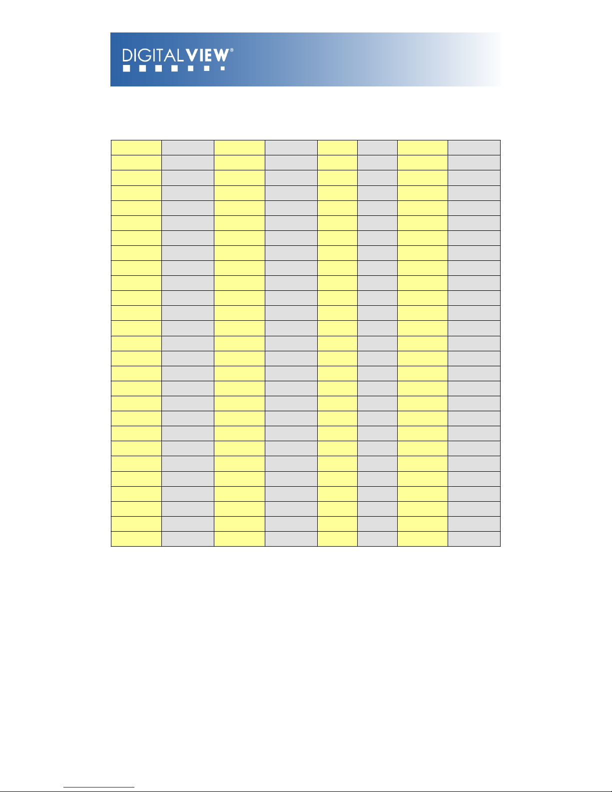
Please refer to the ASCII to Hex convert table below.
Hex to ASCII conversion table
Hex
ASCII
Hex
ASCII
Hex
ASCII
Hex
ASCII
0x30
0
0x41
A
0x61
a
0x2B
+
0x31
1
0x42
B
0x62
b
0x2D
-
0x32
2
0x43
C
0x63
c
0x3F
?
0x33
3
0x44
D
0x64
d
0x34
4
0x45
E
0x65
e
0x35
5
0x46
F
0x66
f
0x36
6
0x47
G
0x67
g
0x37
7
0x48
H
0x68
h
0x38
8
0x49
I
0x69
i
0x39
9
0x4A
J
0x6A
j
0x4B
K
0x6B
k
0x4C
L
0x6C
l
0x4D
M
0x6D
m
0x4E
N
0x6E
n
0x4F
O
0x6F
o
0x50
P
0x70
p
0x51
Q
0x71
q
0x52
R
0x72
r
0x53
S
0x73
s
0x54
T
0x74
t
0x55
U
0x75
u
0x56
V
0x76
v
0x57
W
0x77
w
0x58
X
0x78
x
0x59
Y
0x79
y
0x5A
Z
0x7A
z
© Digital View Ltd 2009
www.digitalview.com
Page 29 of 33
Page 30
Appendix III – Function description for de-interlacing mode AFM, TNR, MADI,
DCDi
AFM = Auto Film Mode:
It is a frame based method that used for the input ODD and EVEN fields have a fixed relation
between each other, such as static image, 3:2 pull down mode.
If two fields are correctly merged, it can get the best quality. But if it merges two wrong fields,
it will have artifact and get the worst quality.
TNR = Temporal Noise Reduction:
It is a frame-based method which assume field-to-field have a fixed relationship.
If the object moving too fast, it will have image artifact and get worst quality.
MADI = Motion adaptive de-interlacing:
It is a pixel based method which used for the input fields have no fixed relation between them
If the object moving very too fast, it will get worst quality.
DCDi = Directional Correlation Deinterlacing :
It is a digital enhancement method developed by Faroudja. DCDi technology is primarily used
for improving the image quality of low resolution images. This is done by deinterlacing the
image and blending rough edges occurring in diagonal lines.
Appendix VII – PIP mix table
VGA
Composite
S-Video
Component
DVI
HDMI
VGA
X
Composite
X
S-Video
X
Component
X
DVI
XX
HDMI
X
X
© Digital View Ltd 2009
www.digitalview.com
Page 30 of 33
Page 31
Appendix VIII – Auto Color Gain
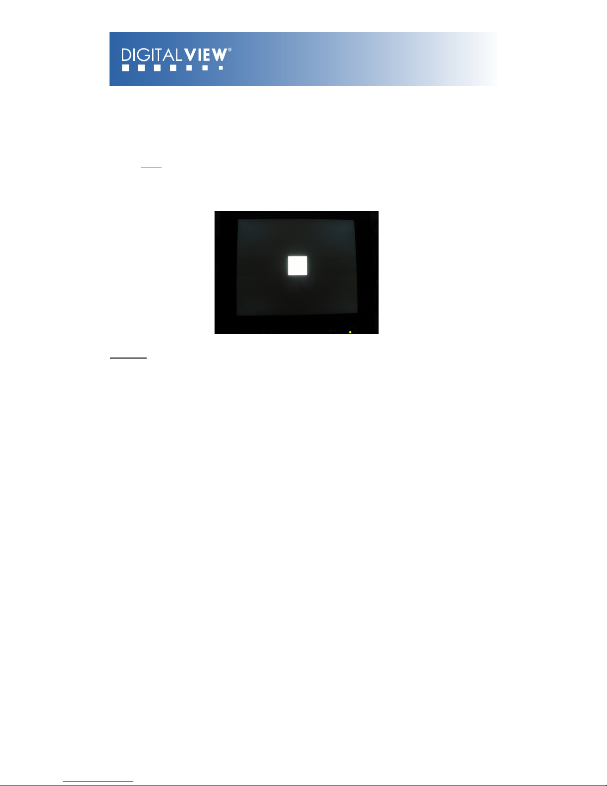
The Auto Color Gain function is supported in the ARGB mode only and is designed
to calibrate the controller to the incoming video signal. In order to calibrate correctly, the
display must be displaying an image containing both black and white data (see illustration
below) when the function is used. The internal processor of the video controller chip will then
execute a process to adjust the relative values of the RGB signals to achieve the best
performance. The parameters of the corrected RGB values are then stored in the controller
and are unaffected by the Reset Factory Defaults function.
Warning - If the Auto Color Gain is executed without an appropriate image being displayed,
then the process will set incorrect values and the display colors will be distorted. If this
occurs, then it can either be corrected by performing the process correctly or if this is not
possible then the Reset Color Gain function can be used. This function will reset the stored
RGB values to a set of approximate values.
© Digital View Ltd 2009
www.digitalview.com
Page 31 of 33
Page 32

WARRANTY
The products are warranted against defects in workmanship and material for a period of three (3)
year from the date of purchase provided no modifications are made to it and it is operated under
normal conditions and in compliance with the instruction manual.
The warranty does not apply to:
•
Product that has been installed incorrectly, this specifically includes but is not limited to cases
where electrical short circuit is caused.
•
Product that has been altered or repaired except by the manufacturer (or with the
manufacturer’s consent).
•
Product that has subjected to misuse, accidents, abuse, negligence or unusual stress whether
physical or electrical.
•
Ordinary wear and tear.
Except for the above express warranties, the manufacturer disclaims all warranties on products
furnished hereunder, including all implied warranties of merchantability and fitness for a particular
application or purpose. The stated express warranties are in lieu of all obligations or liabilities on the
part of the manufacturer for damages, including but not limited to special, indirect consequential
damages arising out of or in connection with the use of or performance of the products.
CAUTION
Whilst care has been taken to provide as much detail as possible for use of this product it cannot be
relied upon as an exhaustive source of information. This product is for use by suitably qualified
persons who understand the nature of the work they are doing and are able to take suitable
precautions and design and produce a product that is safe and meets regulatory requirements.
SAFETY INSTRUCTION
Do not use this product near water, for example, near a bathtub, wash bowl, kitchen sink, laundry
tub, in a wet basement or near a swimming pool.
LIMITATION OF LIABILITY
The manufacturer’s liability for damages to customer or others resulting from the use of any product
supplied hereunder shall in no event exceed the purchase price of said product.
LICENSING REQUIREMENTS
Depending on the features desired, customer/purchaser may be required to obtain a license with the
relevant organizations.
TRADEMARKS
The following are trademarks of Digital View Ltd:
VIEWSTREAM/REMOTE PLAYER
© Digital View Ltd 2009
www.digitalview.com
Page 32 of 33
Page 33

CONTACT DETAILS
USA: Digital View Inc.
18440 Technology Drive
Building 130
Morgan Hill, CA 95037
USA
EUROPE: Digital View Ltd
6 Marylebone Passage
London
W1W 8EX
UK
ASIA: Digital View Ltd
16
th
floor Millennium City 3
370 Kwun Tong Road
Kwun Tong
Hong Kong
Brand names belong to their respective owners.
Specifications subject to change without notice
© Digital View Ltd 2009
www.digitalview.com
Page 33 of 33
 Loading...