

Digital Systems DSF22 Installation And Setup Manual

DSF22
INSTALLATION AND SETUP GUIDE
1/7/2015

DSF22 UNIQUE MONITORING TERMINAL
Contents
Wiring diagram.............................................................................................................................................. 4
Description of wires. ................................................................................................................................. 4
Connection with backup battery. ................................................................................................................. 5
Settings related to digital input status change alert. ................................................................................ 6
Fuel control module. ..................................................................................................................................... 7
Using a vehicle’s standard fuel sensor. ..................................................................................................... 7
Usual connection diagram for standard fuel sensor. ................................................................................ 7
Fuel sensor imitation mode ...................................................................................................................... 7
Settings related to standard fuel sensor usage. ....................................................................................... 8
Using of additionally installed fuel sensor. ............................................................................................... 9
Connection diagram for additional fuel sensor. ....................................................................................... 9
Settings related to additional fuel sensor usage. ..................................................................................... 9
Measured fuel data procession. ................................................................................................................. 10
How data procession works? .................................................................................................................. 10
Settings related to fuel data processing. ................................................................................................ 10
Status indication LED. ................................................................................................................................. 11
GPS module status (Red LED).................................................................................................................. 11
GSM module status (Green LED). ........................................................................................................... 11
Connectivity status (Yellow LED). ............................................................................................................ 11
Fuel theft alarm........................................................................................................................................... 12
How it works? ......................................................................................................................................... 12
Settings related to fuel theft alarm. ....................................................................................................... 13
Vehicle’s battery supervisor........................................................................................................................ 13
How it works? ......................................................................................................................................... 13
Settings related to battery supervisor usage. ......................................................................................... 13
GPRS connection limiter ............................................................................................................................. 14
Settings related to GPRS connection limiter. .......................................................................................... 14
SMS commands. .......................................................................................................................................... 15
Syntax of SMS commands. ...................................................................................................................... 15
Read commands ...................................................................................................................................... 15
Write commands ..................................................................................................................................... 15
INSTALLATION AND SETUP GUIDE
2

DSF22 UNIQUE MONITORING TERMINAL
List of all parameters. ............................................................................................................................. 16
Description of parameters. ..................................................................................................................... 17
Technical parameters. ................................................................................................................................. 42
INSTALLATION AND SETUP GUIDE
3
DSF22 UNIQUE MONITORING TERMINAL
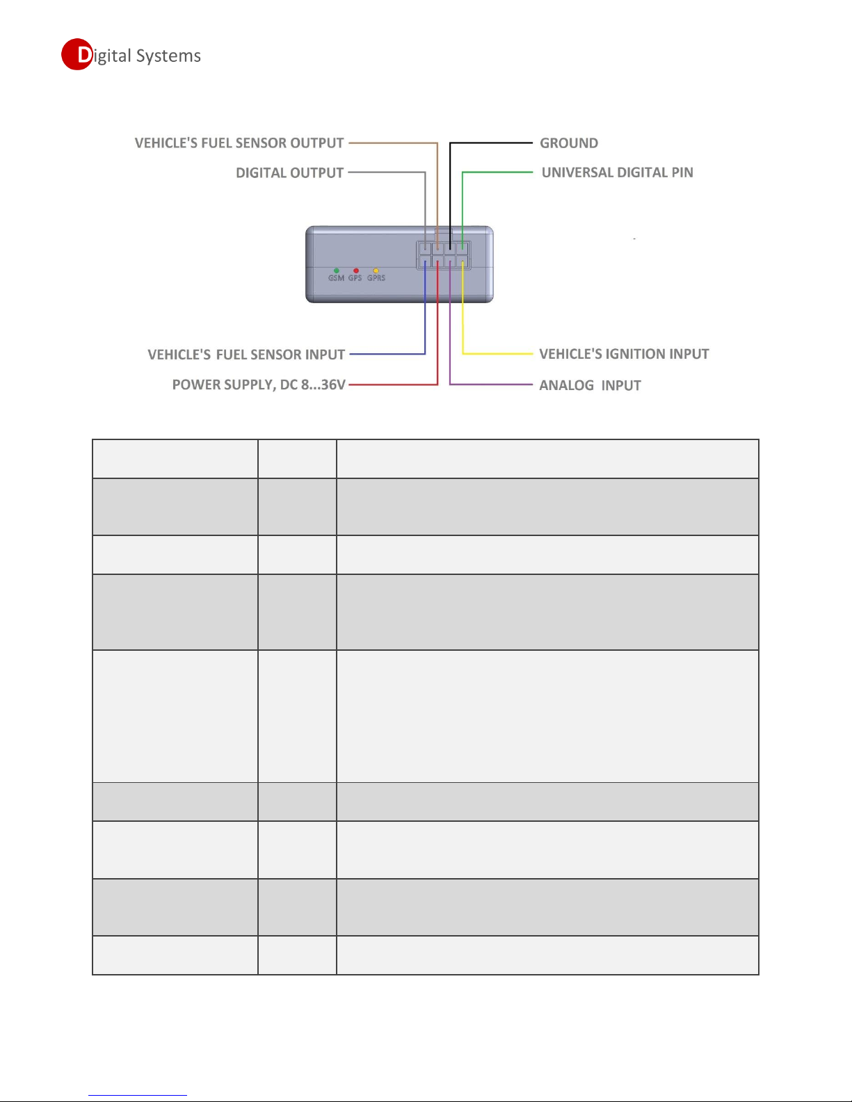
Purpose of wire
Colour of
the wire
Description
Power supply
Red
This wire used to power a GPS/GSM monitoring terminal, must
be connected to positive terminal of vehicle’s battery. Power
supply must be within range 7…36 Volts.
Ground
Black
This wire must be connected to negative terminal of vehicle’s
battery or to vehicle’s chassis.
Ignition input
Yellow
This wire used to monitor a status of vehicle’s ignition, and
switch monitoring terminal from idle to tracking mode. Must be
connected to ignition switch, voltage range for this input must be
within 7…36 Volts (ignition ON state).
Universal digital pin
Green
This is universal pin, by default it’s configured as digital input,
can be used to monitor a status of electrical equipment in the
vehicle, such as lights, door opening, etc.
Can be configured as digital Open-collector output, max load
500mA. Can be used for remote activation some of vehicle
systems, such as lights, heater, etc.
Digital output
Grey
Open-collector output, max load 500mA. Can be used for remote
activation some of vehicle systems, such as lights, heater, etc.
Vehicle’s fuel sensor
input
Blue
Specialized Analog input for vehicle’s standard fuel sensor
connection. See section Connection diagram for standard fuel
sensor.
Vehicle’s fuel sensor
output
Brown
Specialized output used for vehicle’s standard fuel sensor
connection. See section Connection diagram for standard fuel
sensor.
Analog input
Violet
Universal Analog input, voltage measurement range 0…30 volts,
resolution 12 bits.
Wiring diagram.
Description of wires.
INSTALLATION AND SETUP GUIDE
4
DSF22 UNIQUE MONITORING TERMINAL
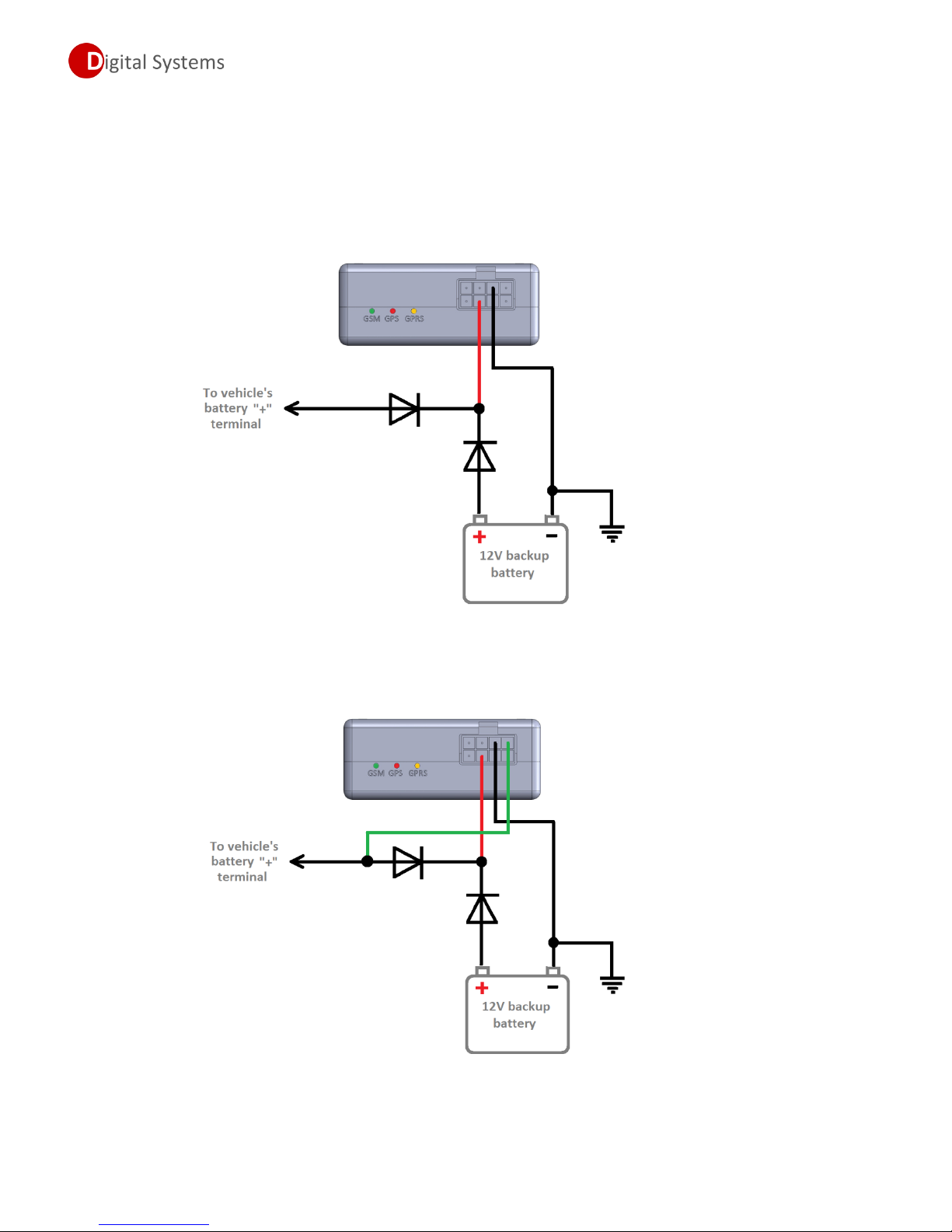
Connection with backup battery.
In some cases where continuous working of terminal is required, even when vehicle’s battery has been
disconnected, it is possible to connect external backup battery. Using this possibility, terminal will
continue working after vehicle’s battery disconnection, and if it’s necessary, terminal can send alert SMS
about vehicle’s battery disconnection. Picture below shows correct connecting diagram:
In case if SMS alert about vehicle’s battery disconnection is desired, following connection must be done:
INSTALLATION AND SETUP GUIDE
5
DSF22 UNIQUE MONITORING TERMINAL
Parameter
Required
value
Comments
P35
0
Configure universal pin as digital input
P42
+xxxxx
User’s phone number 1 (to receive alert SMS)
P48
+xxxxx
User’s phone number 2 (to receive alert SMS)
P62
2
Enable SMS alert, define conditions to trigger alert
Note!!!
Both diodes must be with appropriate forward current, at least 3 Amps, otherwise terminal may
have power drops during data transmissions.
Recommendation!
To keep backup battery charged, we suggest adding a resistor, connected to backup battery
positive terminal and vehicle’s ignition. This connection will provide small charge current for
backup battery during driving.
To activate SMS alert, follow these steps:
1. Set universal digital pin to digital input working mode, P35 must be set to 0;
2. Define User phone numbers to receive SMS alerts, set P42 and/or P48;
3. Enable digital Input status change alert, define alert condition; P62 set to 2
From this moment digital input status change alert is enabled, in case if voltage in green wire will be
lost, terminal will send SMS alert to defined numbers.
Note!!!
In case of digital input status changes, terminal will send only one SMS alert to each defined number,
after that digital input status change alarm becomes passive. Switch ignition ON and then OFF to
activate input status change alarm again.
Settings related to digital input status change alert.
INSTALLATION AND SETUP GUIDE
6
DSF22 UNIQUE MONITORING TERMINAL
Fuel control module.
There are two possible ways to control fuel consumption, each of them have the benefits and
drawbacks, described below. Installer must select one of following options.
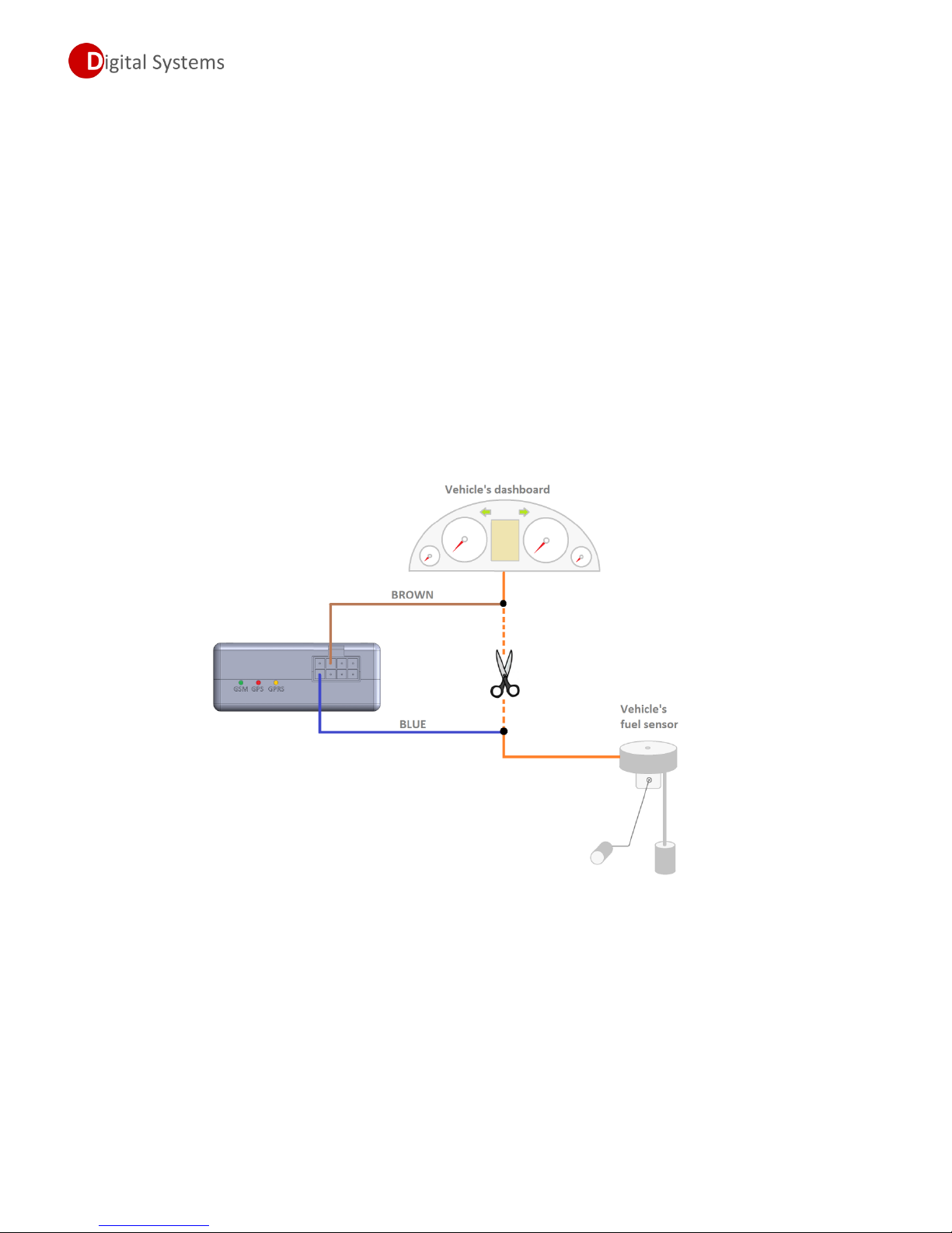
Using a vehicle’s standard fuel sensor.
There is specially designed input to read a vehicle’s standard fuel sensors. As the benefit, this method
allows get information about fuel level without installing additional fuel sensors, this saves money and
time spent for installation. As the drawback of this method is precision of measurements - it can range
from 1 up to 10%, and it is related to vehicle’s fuel sensor type and condition.
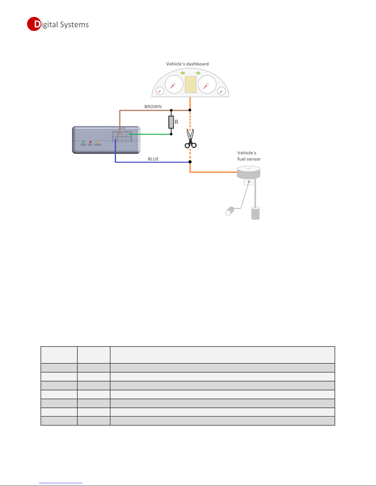
Usual connection diagram for standard fuel sensor.
Picture below shows typical connection diagram suitable for most of vehicles. This connection does not
require any external components.
Fuel sensor imitation mode
For some vehicles, especially latest models of construction machinery and tractors, additional resistor
must be connected; otherwise connection to standard fuel sensor may trigger fault codes on vehicle’s
dashboard.
Resistor value depends on vehicle’s fuel sensor resistance – it’s recommended to use resistor with the
same resistance as vehicle’s fuel sensor or very close to this.
INSTALLATION AND SETUP GUIDE
7
DSF22 UNIQUE MONITORING TERMINAL
Parameter
Required
value
Comments
P31 0 Enable specialized input for reading a vehicle’s standard fuel sensor
P32
15-255
Fuel measurement frequency (we recommend to leave default value)
P33
1 or 0
Enable/Disable Fuel sensor imitation mode
P35
1 or 0
Universal digital pin work mode (output or input)
P50
1 or 0
Enable/Disable fuel data processing (filtering)
P51
5-255
Fuel data processing depth (used only if P50=1)
P52
0-2
Fuel measurement conditions (see description later in this document)
Correct connection diagram for fuel sensor imitation shown in the picture below.
After connecting additional resistor, installer must activate fuel sensor imitation mode in terminal,
following these steps:
1. Configure universal Digital pin to work as Digital output mode by setting P35 to 1
2. Enable “Fuel sensor imitation mode” by setting P33 to1
Note!!!
In case if universal digital pin is configured as digital output (P35 = 1), then this pin cannot be used
as digital input at the same time.
Settings related to standard fuel sensor usage.
INSTALLATION AND SETUP GUIDE
8
DSF22 UNIQUE MONITORING TERMINAL
Parameter
Required
value
Comments
P31
1
Enable external Analog input.
P50
1 or 0
Enable/Disable fuel data processing (filtering)
P51
5-255
Fuel data processing depth (used only if P50=1)
P52
0-2
Fuel measurement conditions (see description later in this document)
Using of additionally installed fuel sensor.
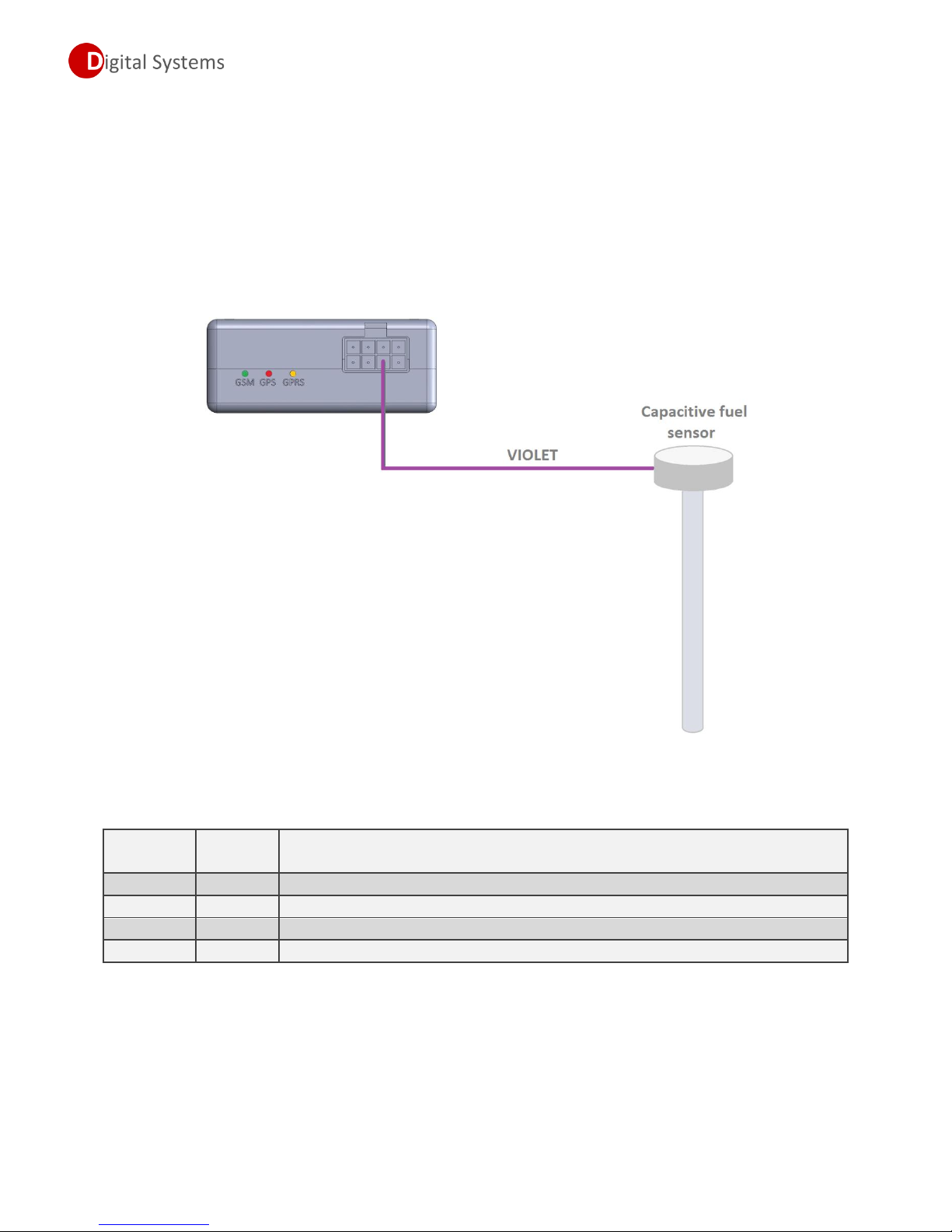
It is possible to use additionally installed capacitive fuel sensor. As the benefit of this method is high
precision of measurements, it is around 0.2-1%. As the drawbacks of this method is high costs related to
the price of fuel sensor and difficult installation. As other drawback is limited possibilities to install
additional sensors – in most cases it is possible to install additional sensors only on trucks, tractors and
construction machinery, no possibilities for passenger cars and commercial vans.
Connection diagram for additional fuel sensor.
Settings related to additional fuel sensor usage.
INSTALLATION AND SETUP GUIDE
9

DSF22 UNIQUE MONITORING TERMINAL
Parameter
Required
value
Comments
P50
1 or 0
Enable/Disable data processing (filtering)
P51
5-255
Fuel data processing depth (used only if P50=1)
P53
1-255
Valid fuel data wait time
Measured fuel data procession.
As vehicle usage is subjected to different movements, it’s difficult to calculate actual amount of fuel
using usual methods. We recommend to enable our unique data procession algorithm, as result of data
procession you will get correct amount of fuel.
How data procession works?
Data procession algorithm is using several input criteria, such as vehicle position (based on
accelerometer), driving speed and driving angle. Based on these parameters, terminal makes data
procession and averaging as result a correct fuel data will be sent to the monitoring server.
Next two pictures demonstrate a difference between processed fuel data and raw data. First picture
shows a fuel curve without using data procession.
Next picture demonstrate a fuel curve using data procession.
Settings related to fuel data processing.
INSTALLATION AND SETUP GUIDE
10
DSF22 UNIQUE MONITORING TERMINAL
Condition of LED
Description of operating mode
Constantly OFF
GPS module switched OFF.
Constantly ON
GPS module is not ready, module setup proceeding.
Fast blinking
GPS module ready, no GPS position detected.
Long blinks
GPS module ready, approximate position available.
Short blinks
GPS module ready, accurate position available.
Condition of LED
Description of operating mode
Constantly OFF
GSM module switched OFF
Constantly ON
GSM module is not ready, module setup proceeding.
Fast blinking
GSM module ready, SIM card detecting/checking mode
Long blinks
GSM module ready, not registered, searching for available network.
Short blinks
GSM module ready, registered in network.
Condition of LED
Description of operating mode
Constantly OFF
No active GPRS sessions, terminal not connected to server
Constantly ON
GPRS active, terminal connected to server, waits for data to be sent.
Fast blinking
GPRS active, data sending process.
Status indication LED.
There are 3 status indication LEDs, which provides visual information about current operating
mode of monitoring terminal.
GPS module status (Red LED).
GSM module status (Green LED).
Connectivity status (Yellow LED).
INSTALLATION AND SETUP GUIDE
11

DSF22 UNIQUE MONITORING TERMINAL
Fuel theft alarm.
With the help of fuel theft alarm it is possible to inform a driver about fuel level change in fuel tank
during parking time. In case if fuel level will be changed, driver will be informed about it via SMS
message. Fuel theft alarm has two channels, one of channels is related to standard fuel sensor input,
and second channel is related to analog input. Both channels can work separately or the same time.
How it works?
Each time when ignition is switched OFF, terminal waits till activation time is finished, than remembers
current level in the fuel tanks. In case if fuel level has been changed more than defined value,
monitoring terminal will send extra event to the server and warning SMS messages to predefined phone
numbers. Using specially designed input, fuel theft alarm works even vehicle’s electronic control units
becomes sleep mode and there are no power on standard fuel sensor.
To setup fuel theft alarm, follow these steps:
1. Enable fuel theft alarm by changing value of parameter P40 (for first fuel tank) and/or P45 (for
second fuel tank). Please remember, this parameter also defines a fuel level drop threshold for alarm
triggering.
2. Set alarm mode by setting parameter P41, this parameter is common for both fuel tanks alarms.
Available options:
a. If P41 = 0 – alert will be send only to server, no SMS will be sent.
b. If P41 = 1 – alert will be sent to the server and SMS alert will be sent to defined numbers.
c. If P41 = 2 – alert will be sent to the server and SMS alert will be sent to defined numbers. Also
Digital Output (grey wire) will be activated for 20 seconds (for siren or light indication)
3. Define phone numbers to receive SMS alert by setting parameters P42 (for first phone number)
and P48 (for second phone number).
4. Define level change direction to trigger fuel theft alert by setting P43 (for first fuel tank) and/or
P46 (for second fuel tank). Available options:
a. If P43/P46 = 0 – alert will be triggered in case of level changes to both directions.
b. If P43/P46 = 1 – alert will be triggered in case if measured fuel value will be increased.
c. If P43/P46 = 2 – alert will be triggered in case if measured fuel value will be decreased.
5. In case if you want to change fuel theft module activation time (default is 20 seconds), change
parameter P44 to required value (time), this parameter is common for both fuel tank alarms.
Note!!!
In case of fuel theft detection, terminal will send only one SMS alert to each defined number, after
that fuel theft alarm becomes passive. Switch ignition ON and then OFF to activate fuel theft alarm
again.
INSTALLATION AND SETUP GUIDE
12
DSF22 UNIQUE MONITORING TERMINAL
Parameter
Required
value
Comments
P40
1-255
Enables fuel theft alarm for first tank and set theft alert trigger threshold
P41
0,1 or 2
Theft alarm mode (common for both fuel tank alarms)
P42
+xxxxx
User’s phone number 1 (to receive alert SMS)
P43
0-2
Fuel level change direction (for first fuel tank)
P44
0-250
Fuel theft alarm activation time (common for both fuel tank alarms)
P45
1-255
Enables fuel theft alarm for second tank and set theft alert trigger threshold
P46
0-2
Fuel level change direction (for first fuel tank)
P48
+xxxxx
User’s phone number 2 (to receive alert SMS)
P52
0 or 2
Allow fuel measurement when ignition is switched OFF
Parameter
Required
value
Comments
P42
+xxxxx
User’s phone number to receive warning message
P60
100-255
Enable battery monitor, set alarm trigger threshold
Settings related to fuel theft alarm.
Vehicle’s battery supervisor.
It is possible to enable a battery voltage supervisor; in this case driver will be informed about voltage
drop via SMS message.
How it works?
Each time ignition is switched OFF, terminal starts to monitor a vehicle’s battery voltage. In case if
voltage level drops below predefined value and remains this condition more than 30 seconds, than
terminal sends SMS alert to predefined numbers. In case is there are short voltage drops, terminal will
ignore it.
To setup battery supervisor, do as follows;
1. Define phone numbers to receive SMS alert message by setting parameter P42 and/or P48.
2. Set voltage threshold to trigger low voltage alarm by setting parameter P60.
Note!!!
In case of voltage drop detection, terminal will send only one SMS alert to each defined number after
that battery supervisor becomes passive. Switch ignition ON and then OFF to activate it again.
Settings related to battery supervisor usage.
INSTALLATION AND SETUP GUIDE
13
 Loading...