

Digital Systems DS512 Installation Manual

manual ver.DS512.IM.EN.0400.028 2015-11-13
Vehicle Security System
GSM/SMS Pager
DS512 ALARM - CAN GSM GPS
INSTALLATION MANUAL
DS512-0400 and higher

DS512.IM.EN.0400.028 Digital Systems
2
Table of contents
1. DS512 OPERATING PRINCIPLE ................................................................................................................. 5
2. DS512 SET ............................................................................................................................................... 7
3. PREPARATION OF SIM CARD ................................................................................................................... 7
4. DS512 CONFIGURATION .......................................................................................................................... 8
5. GSM PAGING PARAMETERS SETUP ....................................................................................................... 11
6. DIAGNOSTIC TOOLS .............................................................................................................................. 13
7. PROGRAMMING OF TYTAN REMOTE TRANSMITTERS ........................................................................... 16
8. BASIC SMS COMMANDS ........................................................................................................................ 16
9. INSTALLATION OF DS512 ....................................................................................................................... 19
10. INSTALLATION OF GPS RECEIVER .......................................................................................................... 20
11. PREPARATION OF THE DS512 TO WORK ................................................................................................ 21
12. GIVING THE SYSTEM TO THE USER ........................................................................................................ 22
13. TECHNICAL DATA .................................................................................................................................. 22
14. DESCRIPTION OF INPUTS/OUTPUTS ...................................................................................................... 22
15. PROGRAMMABLE AUX MODULE OUTPUT/CHANNEL ............................................................................ 23
16. DS512 WIRING DIAGRAMS .................................................................................................................... 25
DIAGRAM 1 - MODE 3 AND MODE 4 - STAND-ALONE VSS .............................................................................. 26
DIAGRAM 2 - MODE 2 - MONITORING OEM CAN-BUS VSS ............................................................................. 27
DIAGRAM 3 - MODE 1 - PAGER FOR ANY THIRD PARTY ANALOGUE VSS ........................................................ 28
DIAGRAM 4 - MODE 1 - PAGER FOR ANY THIRD PARTY ANALOGUE VSS (INPUTS MONITORED) ..................... 29
DIAGRAM 6 - CONNECTION FOR RF MODULE WITH TYTAN REMOTE TRANSMITTERS .................................... 31
DIAGRAM 7 - CONNECTION FOR SECOND ADDITIONAL SENSOR WITH PRE-ALARM ....................................... 32
DIAGRAM 8 - AUX MODULE ........................................................................................................................... 33

DS512.IM.EN.0400.028 Digital Systems
3
TYTAN DS512 ALARM CAN GPS GSM features
• GSM-SMS pager integrated with CAN-bus Vehicle Security System central unit,
• alarming state signalisation with voice call or SMS in GSM network,
• vehicle GPS position is sent only during alarming or after DS512 receives a PIN protected SMS
command,
• if the vehicle GPS position cannot be fixed (e.g. vehicle in underground parking) the device sends last
known vehicle position,
• remote (SMS) control of VSS and remote access to VSS trigger source memory,
• valet mode (service mode),
• operation mode as independent Vehicle Security System with CAN-bus connection to vehicle
electronic systems is armed/disarmed with OEM remotes or SMS commands,
• operation mode as GSM-SMS Pager monitoring for OEM security system via CAN-bus,
• operation mode as GSM-SMS Pager monitoring for any analogue security system already installed
in the vehicle,
• device controlled with simple PIN protected SMS commands or by dedicated Android or iOS
application,
• operation with crash sensor (available only on certain markets),
• internal backup battery allows to notify users even after vehicle power supply breach,
• the device resends to the first programmed mobile phone number any SMS received - e.g. SIM card
provider messages (option),
• vehicle low battery SMS signalisation (option),
• external AUX module with additional programmable output, for example to control auxiliary eating
option),
• immobiliser function with optional alarming in case of unauthorised vehicle start or unauthorised
vehicle entry

DS512.IM.EN.0400.028 Digital Systems
4
Vehicle Security System (VSS) features
• control by OEM remote transmitters
• control by additional Tytan remote transmitters (optional - only with external RF module),
• arming/disarming with SMS commands or dedicated Android or iOS application,
• signalisation if door/trunk/bonnet is open during arming (door ajar),
• when disarming - signalisation if the alarm was triggered,
• CAN-bus control of hazard lights, central door locking, power windows (in some cars),
• analogue control of central door locking and power windows (optional - only with external RF
module),
• additional sensors input
- vehicle interior protection with ultrasonic motion detector (optional),
- vehicle towing and wheel theft protection with additional tilt sensor (optional),
• arming without additional sensors,
• state of the system is stored in non-volatile memory and is saved during power-off.

DS512.IM.EN.0400.028 Digital Systems
5
1. DS512 OPERATING PRINCIPLE
The DS512 is a device that combines function of a SMS pager, stand-alone Vehicle Security System
(VSS), passive immobiliser and Anti-hijack device (only where the reg.97 UN ECE does not apply).
The general purpose of DS512 is to notify up to 3 mobile phone numbers with voice call or SMS
information containing status of vehicle and status of equipped security system.
The DS512 can be equipped with external GPS receiver. This allows to receive vehicle geographical
position in the form of latitude and longitude. SMS notification also includes a link to online maps
which can be opened in any web browser to visualise vehicle position.
The localisation of the vehicle is set only when the alarm is triggered or if the dedicated SMS command
protected by individual DSPIN is sent to the VSS (see user manual).
The DS512 can work without alarm function (VSS) - without optical and acoustic signalisation
of alarming. The device works as a SMS pager that monitors OEM CAN-bus security system or any third
party or OEM analogue security system, already installed in the vehicle.
The 4 modes of DS512 operation are described below:
DS512 operating modes:
Mode 4 - FULL ALARM - complete CAN-bus VSS with audible and visible signalisation.
DS512 is the complete vehicle security system, controlled by OEM remote or Tytan remotes, integrated
with the vehicle via CAN-bus.
In this mode the DS512 monitors the doors, trunk, bonnet and optional additional sensors or OEM
alarm system. When the device is triggered the acoustic (siren) and visible (hazard lights) signalisation
is started and GSM notification procedure is being started. Moreover, triggering of OEM alarm (for
example by OEM internal movement sensor) also triggers the DS512. The door, bonnet, trunk, ignition
and remote control signals are read from CAN-bus (in some cars bonnet and trunk CAN-bus signals
may not be available). Analogue output allows to connect additional bonnet switch if the vehicle is not
equipped with OEM bonnet switch or OEM bonnet switch is not recognised on CAN-bus. The hazard
lights negative output can control the hazard lights switch (perimeter connection) or can control the
relays of analogue connections to hazard lights bulbs. The siren and immobilisation NC relay is
controlled by negative output. The vehicle is immobilised when the VSS is armed and the ignition is
switched on.
The DS512 can be equipped with optional RF module (radio frequency module), which allows to control
the VSS with additional Tytan remote transmitters. The receiver module has 2 outputs, for analogue
control of central door locking (if Tytan remote transmitter is used) and for analogue power windows
control (any remote transmitter is used).
The proper wiring diagram for Mode 4 is diagram 1.
Mode 3 - SILENT ALARM – CAN-bus VSS without audible and visible signalisation.
The DS512 operates as in mode 4, but the audible and visible signalisation is disabled. The engine
immobilisation operates as in mode 4. The appropriate wiring diagram for Mode 3 is diagram 1 without
siren and hazard lights connection.
Mode 2 - OEM PAGER – Pager for OEM CAN-bus security system
The DS512 works as a Pager, monitoring OEM VSS via CAN-bus. Detection of alarming in the monitored
VSS causes the DS512 to notify up to 3 users via GSM about alarming. DS512 does not give any audible
or visible signalisation in this mode. The device does not react on opening the door or switching on the

DS512.IM.EN.0400.028 Digital Systems
6
ignition as long as it does not trigger the OEM alarm. State of doors, ignition and alarm state are read
from vehicle CAN-bus.
The proper wiring diagram is diagram 2.
Mode 1 - PAGER – Pager for any third-party analogue security system
The DS512 operates as an analogue pager to any third-party analogue VSS installed in the vehicle. The
DS512 does not give any visible or audible signalisation. The DS512 does not monitor the doors, trunk,
bonnet and ignition unless violating any of these inputs triggers the monitored analogue security
system. Information of theft attempt is obtained from the monitored analogue security system. The
device has programmable trigger input which, depending on configuration, reacts to positive signal
+12V/+24V NO, positive signal +12V/+24V NC, ground signal NO, ground signal NC. The signal must be
at least 1 sec. long, in order to ignore short siren chirps if the DS512 is connected to the siren circuit.
If minimal connection of just the triggering circuit is used - the proper wiring diagram is diagram 3.
Moreover, in this mode, analogue connections of DS512 can be done to ignition circuit, door signal
and the VSS status signal. These analogue connections are not required, however they allow the DS512
to monitor and send full status of the vehicle (door closed/opened, system armed/disarmed, ignition
on/off). If the VSS status signal is not connected the simplified information about vehicle will be used.
Ignition connection causes the GPS position to be saved during the drive. This is done in case the
vehicle is parked in a place where the GPS signal is weak, e.g. underground parking. Connection of door
status allows to check remotely if the doors are closed or opened.
If the extended connection of the additional signals is used, the proper wiring diagram is diagram 4.
If the DS512 works in Mode 1 it is still possible to choose the CAN-bus level and connect CAN-bus wires
to the vehicle. This allows to read the door status and ignition from the vehicle CAN-bus network and
still monitor the analogue security system by analogue connections.
Remote stop/anti-hijack function.
In the countries, where the Reg. 97 ECE does not apply, in all the operating modes described above,
the DS512 anti-hijack function can be enabled. The anti-hijack sequence is triggered by the SMS
protected by an individual DSPIN. The anti-hijack sequence involves optical and acoustic signalisation,
and after several tens of seconds the vehicle is stopped. The immobilisation relay is active despite the
status of ignition.
In order to have the acoustic and visible signalisation during anti-hijack/remote stop procedure
in modes 1, 2 and 3 the siren and hazard lights connections must be done. These connections are
presented in the diagram 5.
Immobiliser function.
In every mode (1-4), the immobiliser function of DS512 can be enabled. The immobiliser activates 30
seconds after the ignition is switched off and with every arm/disarm of VSS. Until authorisation (with
PA button or Joker remote) the immobiliser does not permit to start the engine. Moreover, the
immobiliser can independently of VSS start alarming (siren, hazard lights and GSM paging):
- if it is not authorised within 30 seconds after ignition on without previous authorisation
(unauthorised vehicle start detection)
- if it is not authorised within 30 seconds after VSS is disarmed and door is open (unauthorised vehicle
entry detection).
These 2 additional protection stages are configurable.
If the immobiliser function is being used, the immobilisation relay must be connected and the ignition
signal must be read – via orange wire or via CAN. If immobilisation alarming is configured, the siren
and hazard lights connections (diagram 5) must be connected. If the DS512 is in mode 1 – analogue
pager and immobiliser unauthorised vehicle entry detection is planned the VSS status wire (blue, pin3)
must be connected and door state must be read -via CAN or with white-red wire (pin3) – diagram 4.
If the Joker remote is used for authorisation, the additional RF module (diagram 6) has to be connected.
DS512.IM.EN.0400.028 Digital Systems
7
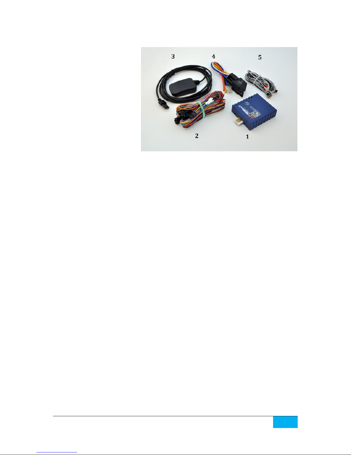
2. DS512 SET
1. main unit (SIM card not
included in set)
2. main wire harness
3. GPS module
4. immobiliser/anti-hijack module
5. LED/valet switch
3. PREPARATION OF SIM CARD
The DS512 can operate in GSM 900/1800 systems with any kind of SIM card. The only condition is to
disable the SIM card PIN code request or setting the SIM card PIN code to 6789 (e.g. with any mobile
phone).
If a prepaid SIM card is used please inform the user about the SIM card term of validity and the need
of maintain funds on the SIM card account in order to keep the possibility of making calls and sending
SMS by DS512.
SIM card phone number must be verified – this will be the vehicle number used for communication
with the DS512.
Some SIM card providers require to perform at least one voice call in order to activate the SIM card.
DS512.IM.EN.0400.028 Digital Systems
8
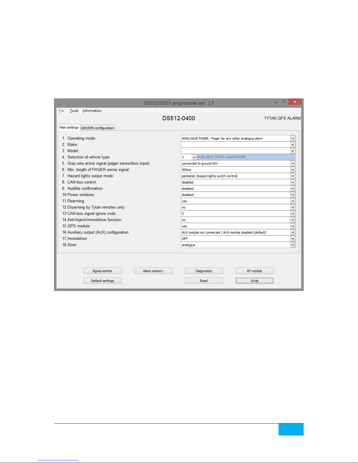
4. DS512 CONFIGURATION
The DS512 will operate in the vehicle only if it has been properly configured. The configuration is made
with a dedicated PC software and the mini USB cable.
The software panel has the list of programmable parameters and few buttons, described below.
- Read loads the configuration from DS512 and shows the settings from the device on the panel.
- Write saves the parameter values shown in the panel to the device.
Parameter list:
1. Operating mode
The parameter selects the operating mode of DS512 as described above (analogue pager/OEM
CAN-bus VSS Pager/Silent Alarm/Full Alarm).
2 - 4. Selection of vehicle type
In order to operate correctly with the vehicle CAN-bus in CAN-bus based modes 2, 3 and 4, the DS512
has to be programmed to a given vehicle model with so-called ‘CAN level’. The CAN-bus level can be
selected according to the table or the wiring diagram for a given vehicle. Moreover, it can be selected
automatically, by choosing make and model of the vehicle from the list. The list is shown when the
‘make and model’ button is pressed.
5. Input active signal pager/bonnet
In modes 3 and 4 grey wire (PIN4) operates as an alarm triggering input, dedicated for connection
of additional analogue bonnet switch or other switch which protects the vehicle. In mode 1 (pager

DS512.IM.EN.0400.028 Digital Systems
9
mode) this wire operates as an analogue alarm-sensing input dedicated for detection of alarming state
of VSS installed in vehicle. In mode 2 this input is inactive.
The active signal of grey wire is programmed. The line can sense ground or positive signal. In case
of ground sense - the internal pull-up in DS512 is activated. In case of positive signal sense, the internal
pull-down is activated. Moreover, the line can react to applying the signal or lack of signal, thus the NO
or NC signals can be handled.
For example in NC- mode:
- the input is inactive as long as the ground signal is applied to the input.
- the input is active as long as the ground signal is not applied to the input.
6. Pager signal length/time
Parameter allows to set minimal signal length of pager output. In mode 1 sensing a signal longer than
length set in programmer is recognised as vehicle violation – the procedure of SMS/voice call
notification starts. Default signal time is 500 ms (0,5 seconds). Choosing 0 causes immediate reaction
after signal is activated. To check the operation of pager output see ‘ALARM Pager’ lamp
in programmer signal monitor.
7. Hazard lights
The recommended method of hazard lights connection is ‘perimeter mode’ - connection of dedicated
DS512 active ground output (pin11 pink-black wire) to hazard lights switch circuit.
DS512 can also control the bulb circuits with analogue high current connection. In such case the hazard
lights connection should be set to ‘analogue’ and additional relays controlled by pink-black wire must
be used - see diagram 1 and diagram 5.
For some specific vehicles like Fiat and Alfa Romeo dedicated 1 wire digital control for hazard lights
and central door locks may be used. In such case set this parameter to ‘Fiat control’ and connect wire
pink-grey to the proper wire shown in Tytan installation schematics.
8. CAN-bus vehicle control
On some vehicles the DS512 can perform a CAN-bus control of:
- hazard lights (in this case the analogue or perimeter connection is not required),
- power door locks,
- power windows.
The information which vehicles allow for CAN-bus control and which circuits can be activated is present
on the vehicle list and on wiring diagrams.
9. Audible confirmation of arming/disarming
IMPORTANT! Audible confirmation can be enabled only in countries where the Reg. 97 does not
apply. In opposite case, the homologation of DS512 as a VSS becomes invalid.
The parameter enables acoustic signalisation of arming/disarming VSS with short siren chirps.
10. Power windows roll-up
The parameter enables power windows roll-up when the system is armed. If the CAN-bus control
is enabled (p. 4.5) the device can control the power windows through vehicle CAN-bus. If the DS512 is
equipped with external RF module with TYTAN remote transmitters, using this feature enables a long
pulse for windows roll up on the analogue door lock output in RF module).
11. Rearming
By default set to ‘Yes’ - in modes 3 and 4 - after disarming with remote transmitter/SMS
command/mobile app the security system waits 30 seconds for any door to be opened. If any door is
not opened during this time the system arms again (so called rearming). Setting this parameter to ‘No’
disables rearming – after disarming with remote transmitter/SMS command/mobile app the systems

DS512.IM.EN.0400.028 Digital Systems
10
stays disarmed until arming with remote transmitter/SMS command/mobile app. ‘No’ setting is
recommended for vehicles/objects that do not have door switches.
12. Disarming by Tytan remote transmitters only
If set to ‘Yes’ parameter allows to operate in mode 3 and 4 as security system that can be armed by
OEM remote transmitter/Tytan remote transmitter/SMS command/mobile app, however disarming is
possible with Tytan remote transmitter/SMS command/mobile app. Disabling disarming with OEM
remote transmitters protects the vehicle with sophisticated theft methods – cloning of OEM remote
transmitters in order to disarm security system.
13. CAN-bus signal ignore codes
Parameter allows to ignore certain signals that appear on vehicle CAN-bus. It makes the system to
work correctly in vehicles where CAN-bus lines send false signals or the device interprets CAN-bus
signals incorrectly. For example: opening the bonnet triggers OEM alarm in vehicle where OEM alarm
is not installed or rear doors are constantly opened in 2 door cars. Proper value of ignore parameter
is a sum of inputs: 1 – door front left, 2 – door front right, 4 – door rear left, 8 – door rear right,
16 – trunk, 32 – bonnet, 64 – OEM alarm, 128 – ignition. For example door front left and bonnet
is 1 + 32 = 33. Default value 0 does not ignore any signals. Any ignored input is not signalised in
programmer signal monitor.
14. Anti-hijack/remote stop enabled
IMPORTANT! Anti-hijack/remote stop can be enabled only in countries where the Reg. 97 does not
apply. In opposite case, the homologation of DS512 as a VSS becomes invalid.
The parameter enables the possibility to initiate anti-hijack sequence - execute remote vehicle stop via
SMS/mobile app. Anti-hijack procedure can be followed by audible and visible signalisation (optional).
15. GPS receiver
By default the DS512 operates as SMS Pager with vehicle GPS localisation. The DS512 can also work
without the GPS receiver – then the GPS receiver should be disabled in the pc programmer in order
not to generate information about inability to fix GPS position.
16. Programmable AUX module output/channel
DS512 can be equipped with external AUX module. It allows to use additional programmable output
OC type. Module allows to control external relays with SMS commands/mobile app. It allows
to control for example auxiliary heaters, trunk release or vehicle lights. Module operation and working
modes are described in chapter 15.
17. Immobiliser
The immobiliser function of DS512 can be enabled – 17th parameter configures the immobiliser mode.
Immobiliser ON - immobiliser when active does not permit to start the engine. The immobiliser is
activated 30 seconds after the ignition is off or immediately after the VSS is disarmed. In order to start
the engine, immobiliser has to be authorised, with Joker remote or with the PA button. Immobiliser
will not activate if the Joker remote is within vehicle range.
ON with alarming 30s. after ignition – If the immobiliser is active and the ignition is switched on, the
30 second timer is started. If the immobiliser is not authorised during that 30 seconds, the alarming of
unauthorised vehicle start begins.
ON with alarming 30s. after disarm and door open – Same as above and additionally the 30 seconds
timer is started if the VSS was armed, then it was disarmed and the door was open. If the immobiliser
is not authorised in that period, the alarming of unauthorised vehicle entry Is started.
 Loading...