

Page 1
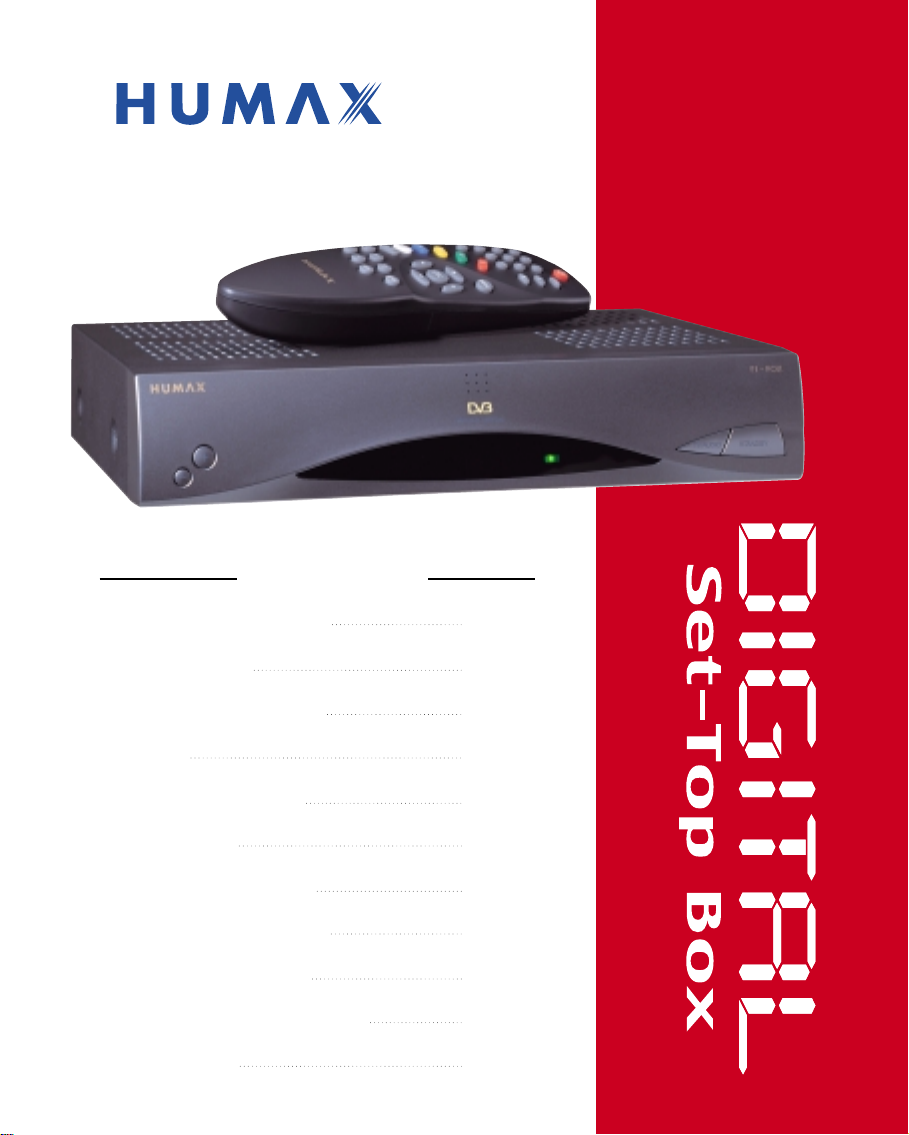
Digital Set-Top Box
for Free-To-Air
User's manual
F1-FOX
Remote Control Unit
Specification
Support & Copyright
Safety
STB Connections
Reference
Guide of Functions
Guide of Main Menu
Motorised System
Trouble Shooting Guide
Menu Tree
1~2
3~4
5
6
7~11
11
12~16
17~33
34~37
38~39
40
Page 2
Remote
Control Unit
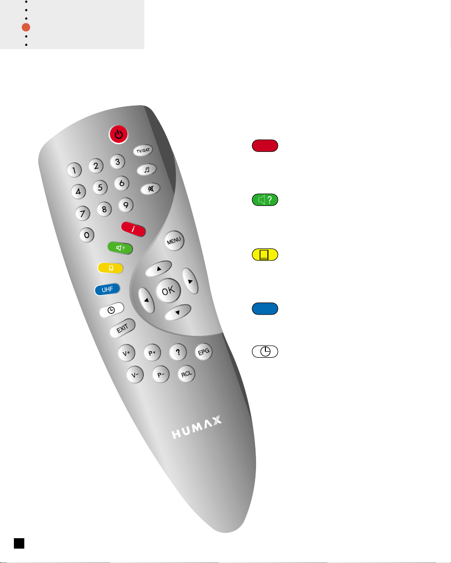
1. Remote Control Unit (RCU)
Information key
i
Displays the programme information
box on the screen and is also used as
the RED key in the menus.
Soundtrack key
Selects the soundtrack list for the
current service and is also used as
the GREEN key in the menus.
Subtitle key
Selects the subtitle language list for
the current service and is also used
as the YELLOW key in the menus.
UHF
1
UHF function is not available on this
STB but this key is used as the
BLUE key in the menus.
Time key
Displays the current time on the right
side of the screen and is also used as
the WHITE key in the menus and
reservation.
Page 3
Remote
Control Unit
TV/SAT
~
09
EXIT
V+
V-
/
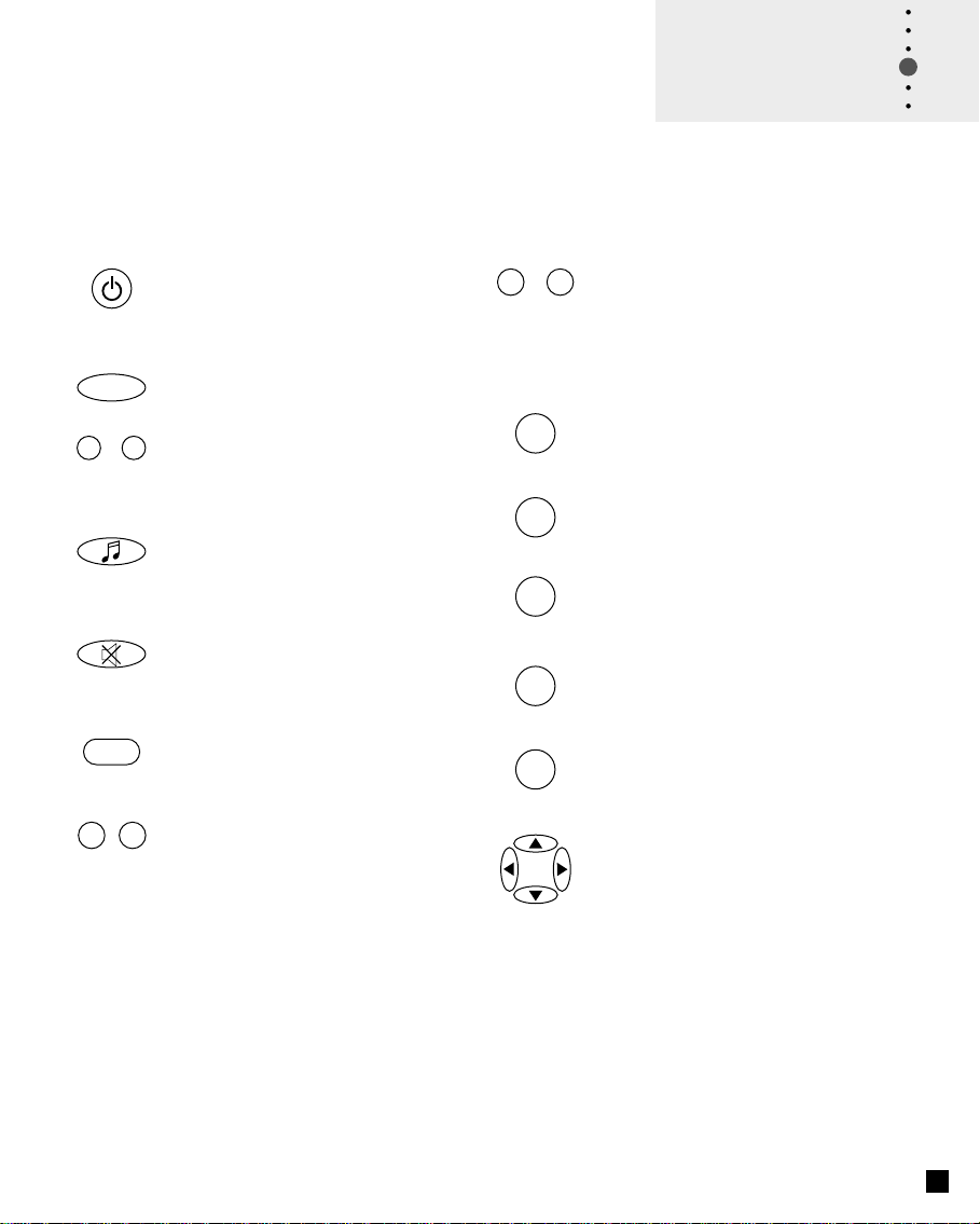
Standby key
Switches between Operation
and Standby mode.
Selects the TV/VCR/SAT mode.
Numeric key
Used to select the service and enter
the channel information and PIN Code.
TV/Radio key
Receiver Switches:
TV/ Radio receive mode
Mute key
Used to enable or disable the
audio.
Returns to the previous menu and
screen.
Volume Up/Down key
Used to increase or decrease the
volume.
P+
/
?
RCL
EPG
MENU
OK
Programme Up/Down key
P-
Used to tune to the next or previous
service.
Used to move up or down a page in
the menu mode.
Help key
Displays the Help box on the screen.
Recall key
Selects the previously viewed channel.
Displays the TV/Radio programme
guide.
Displays the Main Menu on the screen or
returns to the screen from a submenu.
Selects the service list and used to
select the item in the menu mode.
Cursor key
Used to move the highlight bar for
selecting options in the menus and it can
also be used to change up/down
services and to increase or decrease the
audio volume.
Please note : The design of the Remote Control Unit (RCU) may be changed
without notice in advance.
2
Page 4

Specification
The concept OSD is for
On-Screen-Display
; means that Menu displays
on the Screen of TV.
2. STB’S Specification
Tuner & Channel
Input Connector : F-type, IEC 169-24, Female
Frequency Range : 950 MHz to 2150 MHz
Input Impedance : 75Ω unbalanced
Signal Level : -25 to -65dBm
IF Frequency : 480 MHz
IF Band width : 36 MHz
LNB Power &
Polarisation : Vertical : +13.5V
Horizontal : +18V
Current : 500mA Max Overload Protection
22 KHz Tone : Frequency : 22 ± 4KHz
Amplitude : 0.6 ± 0.2V
DiSEqC Control : Version 1.0/1.2 Compatible
Demodulation : QPSK
Input Symbol Rate : 2-31 Ms/s
FEC Decoder : Convolutional Code Rate 1/2, 2/3, 3/4,
5/6 and 7/8 with Constraint Length K=7
MPEG Transport Stream A/V Decoding
Transport Stream : MPEG-2 ISO/IEC 13818
Transport stream Specification
Profile Level : MPEG-2 MP@ML
Input Rate : 60 Mbit/s Max
Aspect Ratio : 4:3, 16:9
Video Resolution : 720 x 576
Audio Decoding : MPEG/MusiCam Layer I & II
Audio Mode : Single channel / Dual channel Joint stereo /
Stereo
Sampling : 32, 44.1 and 48KHz
Memory
Main Processor : TMIPS R3930(81MHz)
Flash Memory : 2Mbyte (Asynchronous)
Program DRAM : 2Mbyte
3
Page 5
A/V & Data In/Out
TV SCART : Video Output(CVBS, RGB, S-VHS)
Audio Output
(Resolution : 20bit DAC, max 2 Vrms)
VCR SCART : Video Output (CVBS)
: Video Input(CVBS, RGB, S-VHS)
Audio Output
(Resolution : 20bit DAC, max 2 Vrms)
AUDIO R/L : Cinch volume and Mute Control
(Resolution : 20bit DAC, max 2 Vrms)
RS232C : Transfer rate 115,200 bps
9 pin D-sub Type
Specification
You can use a special antenna switch
with DiSEqC commands.
When changing channel from ASTRA
to EUTELSAT for example, a DiSEqC
command is sent with the 22KHz tone
through the antenna cable.
The antenna switch will change from
using ASTRA to EUTELSAT.
The concept of DiSEqC is a protective
trademark of EUTELSAT.
Power Supply
Input Voltage : 190 to 250V AC, 50/60 Hz
Type : SMPS
Power Consumption : Max. 30W
Standby Power : 8W
Protection : Seperate internal fuse.
The input shall have lightning Protection
Physical Specification
Size (W x H x D) : 260 x 50 x 180 mm
Weight (Net) : Around 1.3 Kg
Operating Temp : 0˚C to +45˚C
Storage Temp : -10˚C to +70˚C
Storage Humidity : 5% ~ 95% RH(Non-Condensing)
Please note : The specification of the STB may be changed without notice in advance.
Data rate decides the picture quality of
digital TV programmes.
Date rate of about 5-6 Mbit/s coincides
with the picture quality of a
analog TV programme.
4
Page 6

Support &
Copyright
First and foremost, our knowledge of the set-top box marketplace along with technical
expertise differentiates Humax. Moreover, we maintain very close working relationships
with our customers. We take a highly disciplined engineering approach to product
design, manufacture, testing, acceptance, and to technical and maintenance support.
We conduct comprehensive testing of the units, provide complete documentation and
support, and deliver the highest quality, most consistent products on time, every time.
Humax supports you via its homepage with useful information and new software of the
STB. When you have a question about this product and Humax, please refer the
Humax’s homepage.
Homepage : http://www.humax.co.kr
To provide you the convenience of usage Humax has the right to make changes and
improvements to any of the products described in this manual and the manual of the
products without any notice in advance.
Copyright 2000. HUMAX Co. Ltd.
All rights reserved.
5
C
Page 7
Safety
WARNING
RISK ELECTRIC SHOCK
DO NOT OPEN
TO REDUCE THE RISK OF ELECTRIC SHOCK, DO NOT
REMOVE COVER (OR BACK). NO USER SERVICEABLE
PARTS INSIDE. REFER SERVICING TO QUALIFIED
SERVICE PERSONNEL.
This symbol indicates "dangerous
voltage" inside the product that
presents a risk of electric shock
or personal injury.
This symbol indicates
important instructions
accompanying the
product.
This STB has been manufactured to satisfy the international safety standards.
Please read the following recommended safety precautions carefully.
MAINS SUPPLY : 190 ~ 250V AC 50/60Hz.
OVERLOADING : Do not overload wall outlets, extension cords or adapters as this can result in fire or
electrical shock.
LIQUIDS : Keep liquids away from the STB.
CLEANING : Disconnect the STB from the wall socket before cleaning it.
Use a cloth lightly dampened with water (no solvents) to clean the exterior of the STB.
VENTILATION : Do not block the STB’s ventilation slots.
Ensure that a free airflow is maintained around the STB.
NEVER stand the STB on soft furnishings or carpets.
Do not use or store the STB where it is exposed to direct sunlight or near a heater.
NEVER stack other electronic equipment on top of the STB.
ATTACHMENTS : Do not use any attachments that are not recommended as these may cause hazards or
damage the equipment.
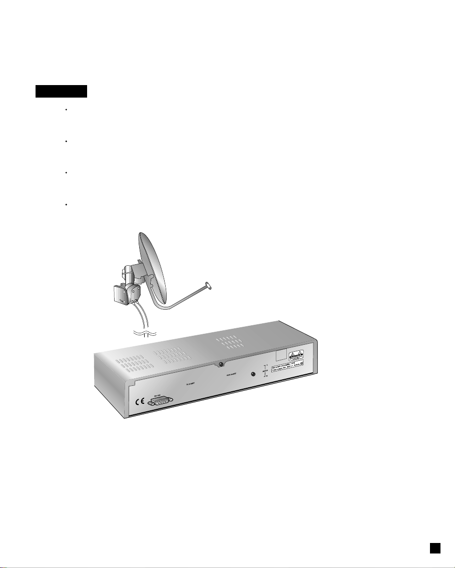
CONNECTION TO THE SATELLITE DISH LNB
: Disconnect the STB from the mains before connecting or disconnecting the cable
from the satellite dish.
FAILURE TO DO SO CAN DAMAGE THE LNB.
CONNECTION TO THE TV or VCR SET
: Disconnect the STB from the mains before connecting or disconnecting the cable from
the satellite dish.
FAILURE TO DO SO CAN DAMAGE THE TV or VCR SET.
EARTHING : The LNB cable MUST BE EARTHED to the system earth forthe satellite dish.
The earthing system must comply with SABS 061.
LOCATION : Locate the STB indoor place properly to prevent lightening, raining and direct sunlight.
6
Page 8
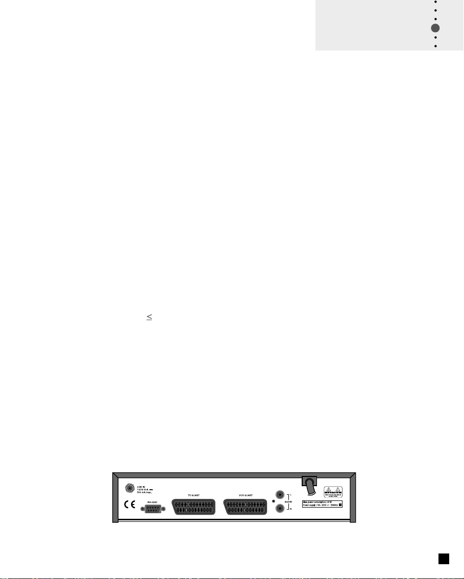
STB Connection
There are several ways of connecting the STB to your existing Audio/TV system.
We recommend using one of the following set-up for best results:
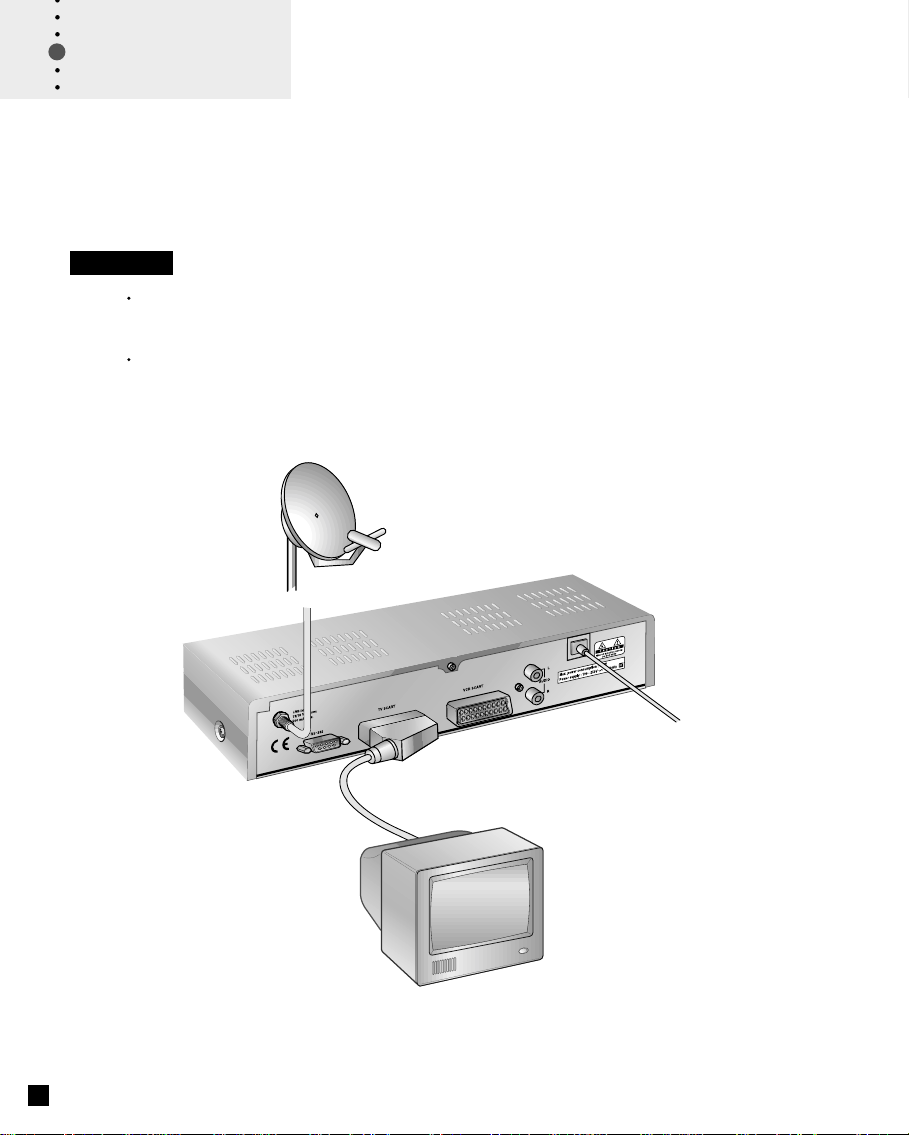
Set-up 1
TV only
Connect one end of a 21-pin SCART cable to the TV SCART connector on the
STB and the other end to a SCART socket on your TV.
Finally connect the coaxial cable from the LNB to the LNB IN socket on the STB.
7
Page 9
STB Connection
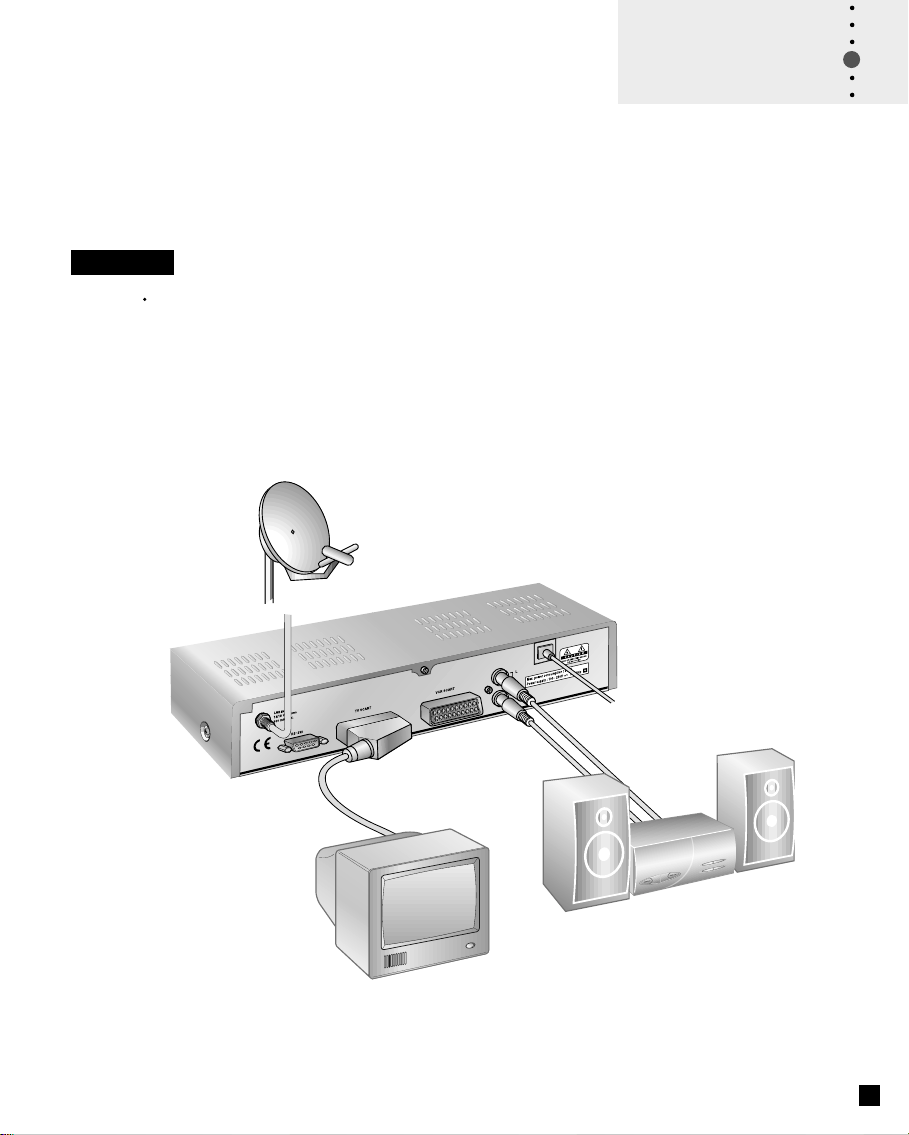
Set-up 2
With Hi Fi System
Connect an RCA/Cinch stereo cable from the AUDIO L, R sockets on the STB
to the LINE, AUX, SPARE OR EXTRA input sockets on your Hi Fi System.
8
Page 10
STB Connection
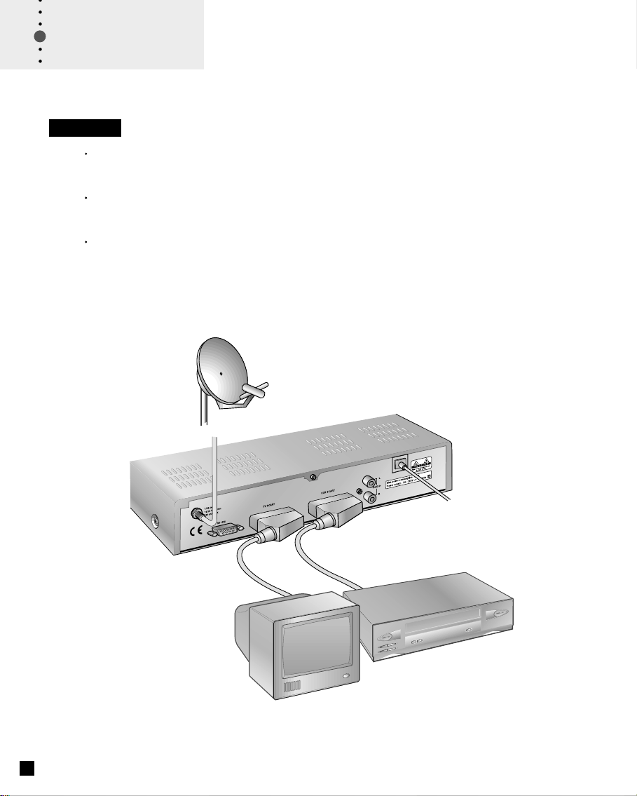
Set-up 3
TV with VCR
Connect one end of a 21-pin SCART cable to the TV SCART connector on the
STB and the other end to a SCART socket on your TV.
Connect one end of a 21-pin SCART cable to the VCR SCART connector on the
STB and the other end to a SCART socket on your VCR.
Finally connect the coaxial cable from the LNB to the LNB IN socket on the STB.
9
Page 11
Set-up 4
TV with VCR and Motorised System (DiSEqC 1.2)
Connect one end of a 21-pin SCART cable to the TV SCART connector on the
STB and the other end to a SCART socket on your TV.
Connect one end of a 21-pin SCART cable to the VCR SCART connector on
the STB and the other end to a SCART socket on your VCR.
Connect one end of your coaxial cable to the LNB IN connector on the STB and
the other end to the REC or Receiver connector on the DiSEqC 1.2 motor.
Connect the coaxial cable from the LNB to the LNB connector on the DiSEqC
1.2 motor.
10
Page 12

Reference
Set-up 5
TV with VCR and Motorised System with Positioner
Connect one end of a 21-pin SCART cable to the TV SCART connector on the
STB and the other end to a SCART socket on your TV.
Connect one end of a 21-pin SCART cable to the VCR SCART connector on
the STB and the other end to a SCART socket on your VCR.
Connect the coaxial cable from the LNB of your motorised system to the LNB IN
socket on the STB.
Connect the motor cables to your positioner (please refer to the manual for your
positioner and actuator)
Connect your positioner to your TV if necessary.
Reference
DiSEqC 1.0 Connection
All our receivers are designed to be DiSEqC 1.0 compatible. This allows
multiple antennas to be connected to the STB at the same time.
If you have two or more fixed antennas or LNBs then we recommend you
use a DiSEqC 1.0 swtich.
Connect the coaxial cable from the first LNB to the LNB 1 or LNB A input
connector of the DiSEqC swtich.
Do the same for any other LNBs that you have.
Connect one end of a Coaxial cable to the RX output connector of the
DiSEqC swtich, connect the other end to the LNB IN socket on the STB.
DiSEqC 1.2 Connection
Please refer to 34 page.
Connection of satellite antenna
To the digital receiver, you can connect either a single satellite antenna
directly or LNB of multi-feed equipment.
11
Page 13
LED of STB
The message of the LEDs(Lighting-Emitting Diode) on the
STB is explained as below.
Guide of
Functions
Upgrade via Satellite and Personal Computer
To maintain the STB up-to-date, it will be possible to
upgrade the software of the STB via satellite and personal
computer. New versions of the software may include new or
improved functions for the current one.
If you want to download and upgrade the software via
satellite, first of all tune your signal to ASTRA Satellite.
When the STB switches into Presentation from Standby
or you choose the STB Upgrade menu, the STB detects
the new software.
If the new software is available, the STB will ask you
whether it downloads the software or not.
If you want to download and upgrade the software via
personal computer, visit our homepage to get more information and the new software.
Page 14

Guide of
Functions
Information Box (I-Plate)
I-Plate displays when the key is pressed or when the
service is changed.
It shows the service part and event part.
When you move to another service, the I-Plate should be
displayed automatically. The time the I-Plate is displayed on
screen is controlled in the Other Setting menu.
SERVICE PART
The contents of the service part are as follows:
- I-Plate Icon, Current Time
- Service Name, Service Number and Service Icon
- Subtitle( ), Teletext( ) or Scrambling Service Symbol( )
- Signal Quality Bar
You can change the service by using the icon to the right
side of the service number. Before playback the selected
service, it will be displayed in red color.
The subtitle, teletext or scrambling service symbol is
displayed when broadcasters of the desired service support
them.
i
13
EVENT PART
The event part displays the information of the current and
next event. To switch from the current event to next, use the
key and from the next event to current use the key.
The contents of event part are as follows:
- Event Name
- Event Duration Time
- Event Description Text
- Reservation Status
You can reserve the programme in the event data display
mode by using the key.
When the current data is displaying on the screen, you can
reset timer programme Once, Daily or Weekly mode.
When you release the timer programme mode, then you will
be asked to confirm the action.
Display the extended event description text by pressing the
? key in the I-Plate with event data displaying mode.
Page 15

Service Change
To change the service, enter the number by using the 0 ~ 9
keys. It is also possible to change the service by using the
P+/P- keys, / keys, Recall, Service list or EPG mode.
To switch between the video and audio service, press the
key.
To select the previously viewed service list, press the
RCL key in the normal A/V playback mode.
Volume Control
To control the volume, press the / keys.
Select the mute mode by pressing the key and to
release the mute mode, press the key again or V+/Vkeys.
Guide of
Functions
Soundtrack
Select the desired audio language of soundtrack by pressing
the key. The soundtrack OSD is displayed by pressing
the key and the initial position of the cursor indicates the
soundtrack currently being used. To listen to the desired
language, select it by using the / keys. In addition
you are able to select between the left and right audio by
pressing the / keys. Exit from the menu by pressing
the OK or EXIT key and the selected audio soundtrack is
maintained.
It is possible to select a desired language from the Audio
Language menu, which will be used as your 1stlanguage if
supported.
14
Page 16

Guide of
Functions
Subtitle
The display of the subtitle are tramitted from the EBU
teletext specification and DVB Bitmap.
Press the key to bring up the subtitle language list for
the current service. Use the / keys to select the
desired language. Then press the OK key to select the
highlighted language, the subtitles will now be displayed.
To cancel the subtitle mode, press the key or EXIT key
again.
Teletext
To view the teletext, you have to use your TV remote control
unit, ( not supplied on the STB’s RCU ) because the teletext
service is controlled by the television.
Service List
To display the Service List, press the OK key. To select the
desired service in the list use the / / / keys and
press the OK key. The Service List provides you the
simple mode and advanced mode. To change the mode,
use the key.
i
move the cursor
previous or next page
select the favourite type or save
the changes
exit from the Service Configuration
15
Service Configuration
In the Service List, you can change the attributes of a
service through the Service Configuration. When the
desired service is selected, press the MENU key. At the
Service Configuration you can change the favourite type,
locking status and make the service skipped or deleted. To
save the changes in Service Configuration, press the OK
key when the cursor is at Lock, Skip or Delete.
Page 17

In the advanced Service List, it is possible to list All or
Favourite service list by using the colour keys as follows:
(red) key - Service List All
i
(green) key - Favourite
A. Service All
The / keys moves the highlight bar to the previous or
next service, using the / keys moves the higlight bar
forwards or backwards by 10 services. Select the desired
service by using the / / / keys. Press the OK key
to view the selected service. The right side scroll-bar of the
screen displays the location of the selected service in
relation to all services.
B. Service Favourite
To add the services to the Service Favourite, use the
Service Configuration at Service All. When you press the
(green) key in the Service List, the favourite service list
will display on the screen. When you want to see the services added to the favourite group, use the / / /
keys.
Guide of
Functions
move the cursor
previous or next page
go to the selected service
change Simple to Advanced list
service list by Favourite
go to the Service Configuration menu
exit from the menu screen
move the cursor
previous or next page
go to the selected service
change Simple to Advanced list
service list by Favourite
go to the Service Configuration menu
exit from the menu screen
16
Page 18

Guide of
Main Menu
move the cursor
open the sub menu
go to the selected menu
exit from the menu screen
Main Menu
The contents of main menu are as follows:
1. TV GUIDE
It shows the programme information and the timer
programming process of the service.
Select the TV Guide mode by pressing the EPG key
in the Video/Audio playback mode.
2. PARENTAL CONTROL
It is possible to control access to certain programmes by setting the parental level or changing the PIN code.
To release the parental block for a service, enter the PIN code.
3. INSTALLATION
It is possible to search for new service and edit the services.
Provides the information about the manufacturer.
4. UTILITY
Provides a Calendar and Biorhythm feature.
page 17~19
page 19
page 19 ~ 33
page 33
17
Page 19

1. TV GUIDE
You can set the reservation and view the programme (event
name) for each service in the TV Guide mode. To access
this mode press the EPG key or select the TV Guide in the
Main Menu. Change between the TV Guide and Radio
Guide by pressing the key.
In the TV guide mode, you can select between four different
modes.
i
(red) key - Shows Now or Next programmes for
the day.
(green) key - Shows programme list for one week.
(yellow) key - Shows the Reserved programme List.
UHF
(blue) key - Shows simple TV Guide on the playback.
TV(or Radio) GUIDE - Now/Next mode
This mode consists of the programme name, event name,
event duration time, current time and displaying box.
Displaying box appears when using the P+/P- keys or
pressing the OK key after using the / keys to highlight
the desired programme. To reserve a desired programme,
move the highlight bar using the / and P+/P- keys
and then press the (white) key. To move through the
pages of programmes use the / keys. To view the
reserved programme list, Select the (yellow) key.
Guide of
Main Menu
move cursor for service selection
previous or next page
move the highlight bar &
display the service
change between Now or
Next programme
show Weekly programme list
show the Reserved
programme list
Simple TV Guide
reserve the programme
display the selected service
exit from the menu screen
TV GUIDE - Weekly mode
This mode displays all the events for the day.
The reservation method of Weekly mode is the same as the
Now/Next mode. If you want to view the event list for
another programme, select the desired programme using
the OK key.
To view the event list for the other days of the week use the
/ keys.
TV GUIDE - Reserved mode
This mode shows the reserved programme(event) list.
You can reserve up a maximum of twenty programmes.
The list displays the programme name, date, duration
time, timer mode and event name. If you want to
cancel the reserved programme, select the programme
using the / keys and press the (white) key.
18
Page 20

Guide of
Main Menu
move the cursor
select the level for blocking
services
enter the digits for PIN code
return to the main menu
exit from the menu screen
TV GUIDE-Quick mode.
This mode shows in the A/V playback mode. The red line
represents the current time and shows the programme
progress status using a Black/White progress bar.
The time range of the bar is made up from the past one hour
and the next two hours.
2. PARENTAL CONTROL
In the Parental Control Menu, you can set the censorship
classification or change the PIN code.
Enter the PIN Code 0 0 0 0 .
Censorship classification : Set the parental level.
If the level displays with the number, it shows the minimum
age for viewing the programme. The kinds of level are "no
block, 6,10,14,18 and total block". To protect the service or
view the programme please enter the PIN code.
Change PIN Code : To change the PIN code, enter the
new code number twice.
move the cursor
go to the selected menu
return to the main menu
exit from the menu screen
19
3. INSTALLATION
Select the "Installation" in the Main Menu mode to select the
submenu. The menu provides settings for customizing, adding new services and displaying the status of the receiver.
3-1. System Setting
The system setting gives you the convenience of selecting
various languages and adjusting the Time and A/V Output
modes. The System Setting mode supports the STB
internal settings according to the connection of the receiver
and external units.
Page 21

A. Language Setting
Menu Language
You can select the desired language on the language list
box by using the / / / keys.
Select the language to be used for On Screen Display
(OSD) like the menu and banner. You can choose the
language from a selection of Czech, Danish, English,
French, German, Hungarian, Italian, Portuguese, Spanish,
Turkish and more. When transmitting the broadcasting
information like event, the selected menu language is
applied first. (Audio language is applied second and then
subtitle. If none of these languages are available then the
first available language is used.)
Audio Language
For service that provide various audio language, select
preferred audio language to used.
When you change the services, firstly the STB tries to
retrieve the language for the previous service in the memory
of STB. If the current service doesn’t provide the language
in the memory, the selected audio language in the Language
Setting will be used secondly. When the selected language
is not available, thirdly the menu language will be used and
then the primary language of the service will be used for
audio language. Czech, Danish, English, French, German,
Hungarian, Italian, Portuguese, Spanish, Turkish and more
can be selected in the Audio Language.
Subtitle Language
This service provides various subtitle languages so that user
can select desired language.
Guide of
Main Menu
move the cursor
go to the selected menu
return to the previous menu
exit from the menu screen
move the cursor
select the language you want to set
on the language list
return to the previous menu
exit from the menu screen
Language List
select the language you want to set
confirm the language and returns to
the Language Setting menu
return to the language setting menu
20
Page 22

Guide of
Main Menu
move the cursor
select your preferences
adjust the wake-up or sleep time and
selects the wake-up service number
return to the main menu
exit from the menu screen
B. Time Setting
Current time
To set the current time, input the offset value by using the
standardized information of current service area. The time
setting will be used as the standardised time for the I-Plate,
TV Guide and Wake-up / Sleep timer.
Current time is based on the TDT(Time Description Table) at
the stream of the current service. The adjustment step unit
is 30 minutes by using the / keys. If the stream of
current service doesn’t contain the TDT, the Current Time
cannot be set up and the Time Offset will be displayed in
grey.
Wakeup Time
Select the time in which the STB will power on according to
the timer or make the timer disabled.
Wakeup Service No.
Select the service number in the STB power on mode, select
the TV or Radio by pressing the key.
move the cursor
select your preference
return to the previous menu
exit from the menu screen
21
Sleep Time
Enter the time for the STB switching off to standby mode
according to the timer set type.
C. A/V Output Setting
Video Output(CVBS/RGB/S-VHS)
Set the Video mode for the TV SCART output.
Audio Output
Set the Audio mode which is output from the TV SCART and
RCA Jack.(Stereo/Mono)
Screen Mode
Select the screen format of TV which is connected to the TV
SCART of STB.(4:3 or 16:9)
Display Format
Select the format which the video is to be displayed on
screen.
Page 23

D. Other Setting
OSD Transparency
Sets the level of transparency for the menus displayed on
top of the video picture.
Information Box Display Time
Sets the length of time the information box displayed on
the screen after changing the service.
Guide of
Main Menu
3-2. Service Organising
This menu gives users access to options that allow them to
organise their Networks, TV services and Radio services.
The default PIN Code is 0 0 0 0 .
A. Organise TV Services
Organise All Services
This mode allows users to Delete, Move, Lock, Skip and
Rename TV services.
Delete
1. You can delete unwanted services using the (red)
i
key.
2. Mark the services that you want to delete in grey colour.
3. Press the OK key.
4. If you want to cancel the deletion, press the EXIT key.
Move
1.You can move the service to wanted position using the
(green) key.
2. The icon( ) will be marked in front of the service
number.
3. Select new position with the / / / keys.
4. Press the OK key.
5. If you want to return to the original position, press the
EXIT key.
move the cursor
select your preference
return to the previous menu
exit from the menu screen
move the cursor
enter the digits for PIN code
go to the selected menu
return to the previous menu
exit from the menu screen
Lock
1. You can lock the services using the (yellow) key.
2. The symbol " " will be marked beside the service name.
3. After a service is locked, you will need to enter the PIN
code in order to view it.
move the cursor
go to the selected menu
return to the previous menu
exit from the menu screen
22
Page 24

Guide of
Main Menu
move the cursor
previous or next page
delete the selected service
move the desired service
lock the selected service
skip the wanted service
change the service name
Skip
1. You can skip the services using the (blue) key.
UHF
2. The symbol " " will be marked beside the service name.
3. When skip is set for service, you will not be able to view it
when moving through the channels using the P+/ P- keys.
You will be able to view these services when selecting the
channel using the 0 ~ 9 keys, service list or the EPG
key.
Rename
1. You can change the service name using the (white)
key.
2. When you press this key, the keyboard screen will be
displayed.
3. Enter the new service name on it.
You can use the four direction keys to move or select the
services.
; to move the previous service
; to move the next service
; to move back by 10 services
; to move forwards by 10 services
You can move through 20 services by using the P+/Pkeys.
move the cursor
previous or next page
move the selected service
23
Note: The box located between service list and the
explanation of the color keys offers the brief information
for services that a cursor is located in.
Organise Favourite TV Services
This mode serves to add and delete services to and from the
favourite group.
To add services into Favourites, locate the cursor to the
desired service and press the OK key. The function of the
colour keys is the same as Organise All Services, except for
the following differences.
When you delete a service in the Favourites window, the
service is excluded from the favourite group and the service
is still stored in Services window.
You can move the service only within Favourites window.
Page 25

To group the services into Favourite;
1.
Move the cursor to 'All TV Services'- plate (right) by using
the key.
2. Select the service you want to group into Favourite.
3. Press the OK key.
4. Move the cursor to "Favourite-plate"(left) by using the
key.
5. Press the OK key to save the selected group.
Note: You can move the cursor to plate by using the / keys and
select the previous and next page by using the P+/P- keys.
B. Organise Radio Services
This function is the same with TV services except that it
uses radio services. You can delete or move each radio
services and change the radio services attributes.
Organise All Services
This submenu allows the user to rename, delete, move,
skip or lock each radio services on all radio service list.
Guide of
Main Menu
Organise Favourite Radio Services
This menu allows the user to add, delete, move, skip, lock or
rename each radio services in the favourite radio services
and group them into the favourite radio services.
The way to group the services into Favourite is same to that
of TV Services(Page 23).
24
Page 26

Guide of
Main Menu
move the cursor
go to the selected menu
return to the previous menu
exit from the menu screen
C. Organise Networks
You can edit the service by using the unit of network.
In the above mentioned picture, the network names are
displayed on the left side and the TV/Radio services con
tained within the highlighted network are displayed on the
right side.
When the number of TV/Radio services for the network is
too many to be displayed in the window, then move the
cursor to the right window using the key and move to
the next list by using the / and P+/P- keys.
In the picture(left), you can check what services are available
for the current network. The operation of Delete/Move/
Rename is available for network only. When the number of
services is under 10, the key is not displayed. In radio
service icon is marked in front of service number.
3-3. Service Searching
After inputting the PIN Code 0 0 0 0 , You can enter the
Service Searching menu as you enter the Parental Control or
Service Organising menu.
The bar displayed at the bottom of
submenu shows the signal quality(BER) for the parameters
entered. After setting the above mentioned parameters,
press the OK key to start service search.
A. Antenna Setting
Selects the Antenna and LNB setting conditions for Service
search. As you can change the settings for 22KHz tone and
DiSEqC switch, there are 16 possible antenna setting for use.
The values that are set in this menu will be available for
selection in other service searching menus.
move the cursor
select LNB frequency or parameters.
In Satellite Name, selects the name
on the satellite list.
input the LNB frequency directly
go to the manual search menu
return to the previous menu
exit from the menu screen
25
Antenna Alternative
There are 16 antenna alternatives, each one can have different combinations of settings for 22KHz tone and DiSEqC
switch.
Page 27

Satellite Name
Selects the satellite name that corresponds to the value of
the Antenna Alternative.
1. Press the / keys to display the Satellite List box.
2. Select the wanted satellite name.
3. If the desired satellite name is not in the list then select
User Defined.
4. The keyboard will appear and you can input the satellite
name directly. The selected satellite name can be help to
select the antenna alternative in the searching menu, but
it is only possible to change or select the satellite name in
the Antenna Setting menu.
5. Satellite name list is put in alphabetical order and the
order can be changed according to menu language.
6. When inputting the satellite name,there is a 16 character
limit.
LNB Frequency
1. Select the L.O. Frequency that is set to antenna.
2. You can select the LNB frequency of 5150, 9750, 10600,
10750, 11475MHz or Universal by using the / keys.
3. If the required LNB frequency is not available, then select
"0" and enter the frequency manually using the 0 ~ 9
keys.
4. When you select Universal LNB, both 9750 and 10600
MHz are supported at the same time, and therefore the
22KHz tone setting is not needed. (Disabled)
Guide of
Main Menu
selects the satellite name you want to find
confirm the satellite name and returns
to the antnna setting menu. If you press
OK key at ‘User Defined’, then the
character table will displayed and you
can input the name on the keyboard.
return to the antenna setting menu
exit from the menu screen
22KHz Tone
In case you are using a Dual LNB or two antennas
connected to a 22KHz tone switch box, make 22KHz tone
switch Enable or Disable to select LNB or antenna.
DiSEqC Input Selection
According to the option and position of DiSEqC switch select
from A to D of DiSEqC and Disable. After setting the abovementioned value, press the OK key (except in Satellite
Name) to move to the Manual Search menu directly.
26
Page 28

Guide of
Main Menu
Motorized System
It is used to set the DiSEqC 1.2 motor by Eutelsat specification. If you wish to use this system, please refer to page 34
for instructions.
Service Search OSD
If you press the EXIT key during the search, service
search stops and the searching menu appears.
When you find all the services the following picture
appears.
Before saving it, you can select the service you want to
delete.
Found services OSD
The picture above shows services that are found after
manual search.
You can mark the services that you don’t want to save
using the (red) key, these services will turn grey. To
unmark a service, select the service and press the (red)
key on it again.
Press the OK key to save, or press the EXIT key to exit
without saving.
Then Manual Search menu appears. When you exit all
menus, the first service of the found service list is played.
i
i
27
In the bottom of found service picture, network, the information of transponder and the number of found service that the
services belong to are displayed. The deleted service by the
i
(red) key is excepted from counting of the number of
sevices.
At the bottom of the screen that shows the services found in
the search, the information of transponder and the number of
found services that the service belongs to are displayed. The
deleted service (using the (red) key) is not included in this
number.
Free means the empty part of all service memory, this is the
amount of space available to store other services in the
future.
i
Page 29

B. Manual Search
After setting the search parameters like frequency, symbol
rate etc., you can find the services manually in the
transponder you have selected.
Antenna Alternative
Select the target antenna for manual search. This antenna
alternative number is already set in Antenna Setting menu.
Antenna alternative 16 is for SMATV.
Guide of
Main Menu
SMATV Search
In case that several generations use Antenna and LNB in
common, as the frequency range of signal is input to IRD is
down as much as LNB L.O.(Local Oscillator) frequency,
search the service from 950 to 2150MHz.
Frequency
Inputs not RF frequency but the frequency that is down
converted through LNB in common. The unit is MHz and
the range of input is 950-2150MHz.
Symbol Rate
Inputs the symbol rate of the signal you want to find.
FEC
You can select the value of 1/2, 2/3, 3/4, 5/6, 7/8 or Auto.
LNB Power
As there is whether the LNB power of STB is necessary or
not according to the sort of IF-IF converters, select a
suitable option for situation.
Satellite Name
It is helpful for selecting the above mentioned antenna alternative. This has been disabled, it is for reference only and
cannot be changed within this menu.
Frequency
Input the frequency of the transponder you want to find
manually.
move the cursor
select the searching parameters
input the frequency, symbol rate
directly
start the SMATV search
return to the previous menu
exit from the menu screen
move the cursor
select the searching parameters
input the frequency, symbol rate
directly
start the SMATV search
return to the previous menu
exit from the menu screen
28
Page 30

Guide of
Main Menu
Polarisation
Select the polarisation of the transponder you want to find.
(Horizontal/ Vertical/ Auto.) In horizontal case, 18V and in
vertical case, 13V are output through LNB line.
Symbol Rate
Inputs the symbol rate of the transponder you want to find.
FEC (Forward Error Correction)
Select the FEC of the transponder you want to find.
You can select the value of 1/2, 2/3, 3/4, 5/6, 7/8 or Auto.
Network Search
You can select Yes or No. When you select 'Yes', you
can find more
As it refers to NIT during searching, if there is the
frequency information of other
the other
inputs.
Automatic Skip
You can select Yes or No. When you select 'Yes', the
search will skip all scrambled services.
When the locked service is scrambled during searching,
You can skip this service not to save. Refer to descriptor
of PMT whether it is scrambled or not.
transponder
transponder
s using the home network.
transponder
besides
transponder
, it searches
the user
29
Page 31

Advanced...
Performs a manual search with the ability to enter
PID(Video/Audio/PCR) values. This mode is necessary
when the signal you search for a signal.
The setting of the sub items is the same as Manual Search.
Video PID/ Audio PID/ PCR PID
You can set the PID to search the service.
It is possible that you input PID by decimal or
hexadecimal system. You can select this mode with the
/ keys.
You can input a decimal PID value by using the 0 ~ 9
keys on the RCU.
In hexadecimal input mode, press one of the 0 ~ 9 keys
to display a hexadecimal keyboard, then you can input a
hexadecimal PID value on it.
When there is no PID input (Auto is displayed), it is the
same function with Manual Search.
After setting the above-mentioned value, press the OK key
anywhere to start service search directly. The picture and
found service list during search are the same with Manual
Search.
Guide of
Main Menu
move the cursor
select the searching parameters
input the frequency,
symbol rate or PID value directly
start the advanced search
return to the previous menu
exit from the menu screen
30
Page 32

Guide of
Main Menu
move the cursor
select the searching parameters
and type
input the symbol rate directly
start the Automatic search
return to the previous menu
exit from the menu screen
C. Automatic Search
When you enter the Satellite Name that is set in Antenna
Setting menu, search all of the selected satellite without
inputting the extra frequency.
Antenna Alternative
Select the target antenna for automatic service search.
The attribute of this antenna alternative number is already set
in Antenna Setting menu and the satellite name is helpful in
the selection of the antenna, but in this menu you cannot
change the satellite name.
Searching Mode
You can select one of two modes (Quick or Detail).
When you select Quick mode, it searches the service by
search parameters that is preset.
When you select Detail mode, it searches the service
through all field of tuner(950-2150MHz).
Detail Mode
The pre-fixed symbol rate list is changed according to
antenna alternative and satellite name. If you want to add or
change it, press the (red) key. The picture of the symbol
i
rate Add/Change mode is as follows:
1. You cannot change or delete the grey coloured part of the
above box that marks symbol rate.
2. You can add, delete or change the white coloured part of
the above box that marks the symbol rate.
3. To add the symbol rate, move the cursor to blank box and
input the symbol rate that you want to add using the 0 ~ 9
keys.
4. Press the OK key to confirm.
5. If you want to go back to the previous figure during
inputting of symbol rate, press the key.
To change the symbol rate, move the cursor to the position
that you want to change and input the new symbol rate.
To delete a symbol rate in the above list, press the Red
key in the selected position and then the symbol rate disappears. The range of symbol rate that is input
additionally is 16-30Ms/s.
6. Press the EXIT key to return Automatic Search menu.
31
Page 33

Automatic Skip
Option to search only Free-To-Air services.
The picture on the right tries to search with varying
frequency, symbol rate and FEC etc.
Note: But, the user should select the satellite name in Antenna Setting
menu and when the user inputs the satellite name separately, you
should select the Detail mode.
Press the OK key anywhere to start automatic search.
The picture during searching is as follows.
The right picture tries to search with varying frequency,
symbol rate and FEC etc. Satellite name is the name that
the user selects to correspond with antenna alternative of
antenna setting. The bar graph that displays on the bottom
of picture shows the progress extent with percent (%).
During the search, services that are found are displayed as
follows:
1. Press the EXIT key during automatic search to stop
search.
2. When finishing search, the message that it is finished
appears.
3. Press the OK key to return Service Search menu.
Guide of
Main Menu
3-4. Satus
A. STB Status
Displays the information of H/W version, S/W version,
Loader version of STB.
B. Signal Detection
Shows the Signal Level (AGC level) and Signal Quality
(BER) of the
current service and is help to the initial
antenna setting.
32
Page 34

Guide of
Main Menu
C. STB Upgrade
You can download and upgrade the software of this STB
through ASTRA satellite when the software of new version is
released.
During downloading don’t turn off the STB.
In case of power off turn on the STB and the downloading
process will be continued.
3-5 Default Setting
When you press the OK key at the screen as blow, the data
of system setting will be changed into the default values and
some free-to-air services of Astra1 will be stored in
replacement of all services found. If you press the EXIT
key, the function will be cancelled and return the Installation
menu.
33
4. UTILITY
STB supports additional functions such as Calendar and
Biorythm.
At the Biorhythm use the / / / keys to adjust your birth
year and date to see your current biorhythm status.
Page 35

Motorised
System
DiSEqC 1.2 User Instructions
If you have a DiSEqC 1.2 motorised system, then you can take advantage of the DiSEqC 1.2 functions available.
The following instruction describes how to use the DiSEqC 1.2 functions to store the positions of the satellites and
to search for the channels(STAB Rotor Sat motor recommended).
1. Satellite Setting Menu Options
When DiSEqC Motorised System is Enabled in the Antenna Setting, a new menu is available for configuring the
motor. This menu is called Satellite Setting and is accessed by pressing the OK key while the option Antenna
Alternative is highlighted in the Manual Search menu. The following options are available on the Satellite Setting
menu.
Satellite Name
A selection of satellite names that can be used to identify a motor position. If the satellite name you require is not
available, please use other. In installer mode the Satellite Name Reference refers to the 0 position of the motor.
Movement
In User mode this is used to fine-tune the position of the motor for better reception. In Installer mode this is used
to search for the position of a satellite manually.
Motor Control
Search : Begin searching for channels on the chosen transponder.
Goto : Moves the motor to the stored position of the selected satellite name.
Store : Stores the current position of the motor for the selected satellite name.
Reset : Resets all stored positions of the motor relative to the 0 position. (Installer mode only)
DiSEqC Command Mode
Changes the current mode between Installer and User.
2. Setting your Receiver for DiSEqC 1.2
You must set your receiver up so that it is ready to use DiSEqC 1.2. To do so, do as follows
1. Press the MENU key, you will now see the Main Menu.
2. Select Service Searching option and press the OK key, you will now
see the Service Searching menu.
3. Select Antenna Setting option and press the OK key, you will now see
the Antenna Setting menu.
4. Set your Antenna Alternative to 1 by highlighting it using the
/ keys and changing the settings using the / keys.
On this menu you must configure your LNB Settings as well.
5. Set the Motorised System to Enable using the
6. The option DiSEqC Input Selection should now be disabled.
This option is used for DiSEqC 1.0, and cannot be used in conjunction with DiSEqC 1.2.
Please note: If you change the Motorised System setting then all previously
stored channels will be deleted,since each system is not compatible.
Your receiver is now ready to use DiSEqC 1.2. To return to the Main Menu, use the EXIT key until you are at the
Main Menu.
/ / /
keys.
34
Page 36

Page 37

Motorised
System
10. Use the Signal and Strength Quality bar at the bottom of the screen to judge the best position of the dish.
11. Use the / keys to stop the motor when required.
12. When you have the best position of the dish go to the Motor Control option and using the / keys
select Store and press the OK key. The position of the satellite should now be stored.
13. If you do not store this position, it will be lost when you exit the menu.
14. Repeat the process for each satellite if required.
5. Moving to a pre-set satellite
Once you have stored the positions of the satellites you want (see left below) you can now search for the chan
nels transmitted from them. Before you can do this, you must move the motor to the position of the satellite you
wish to search. To do this, you must access the Satellite Settings menu. Do as follows ;
1. On the Main Menu, select Service Searching option and press the OK key, you should now see the Service
Searching menu.
2. Select the Manual Search option and press the OK key, you should now see the Manual Search menu.
3. Select the Antenna Alternative option and press the OK key, you will now see the Satellite Settings menu.
4. In the Satellite Settings menu ensure that you have DiSEqC Command Mode option set to User.
5. Highlight the option Satellite Name and use the / / / keys to select the satellite you want to view.
6. When you have selected the satellite you wish to view, go down to the Motor Control option and again
using the / keys select goto and press OK key.
7. The motor will now move to the position of the selected satellite.
8. The Movement option is used to fine-tune the position of the motor.
9. When using the Movement option for fine-tuning, you must remember to store the changes you have made
or else these will be lost.
6. Searching for channels on your selected satellite
Once you have moved the motor into position, you can search for the channels transmitted from it. To search for
channels on your new selected satellite, Do as follows ;
1. Move the motor to the position of the satellite you wish to search.
(see section 5 above)
2. On the Main Menu select the service searching option and press
the OK key. You will now see the Service Searching menu.
3. Select the manual search option and press the OK key. You will
now see the Manual Search menu.
4. Now enter the Frequency and Symbol Rate using the 0 ~ 9 keys.
Next enter the Polarisation and FEC values using the / keys.
5. When you have entered all these details in, press the OK key and
the search will begin.
6. When the search has finished, press the OK key to view.
7. Repeat the process for all the transponders you want from this satellite.
36
Page 38

Page 39

Problem Solution
Does not display any
message on the front panel or
STB has no power.
Trouble
Shooting Guide
About STB
Check the main power cable and check that it is plugged into a
suitable power outlet.
Check whether STB is in Standby mode.
No Picture
Poor picture quality
No Sound
Remote Control does not
operate
No or Bad Signal
Ensure that the STB is switched on (see above).
Check the video output port (SCART) is firmly connected to
the TV or VCR.
Check that you have selected the correct channel or Video
Output on your TV.
Check the brightness level of the TV.
See "No Picture" above.
Check the signal level, if this is low then try adjusting the
alignment of your dish.
See "No Picture" above.
Check the volume level of the TV and STB.
Check the Mute status of the TV and STB.
Point remote control directly towards the STB.
Check and replace batteries.
On-Screen Error Messages
Check the LNB - replace LNB if necessary.
Check the cable from the LNB.
Check the position of the dish - realign dish if necessary.
If you are using a DiSEqC 1.0 switch, check that you have
connected the LNBs to the correct connections on the switch.
Check the "Signal Strength" and the "Signal Quality" in the
Signal Status menu.
38
Page 40

Page 41

40
Page 42

Page 43

HQFOX.200
 Loading...