

Page 1
THUNDER 10000sx
Super High Brightness Digital Video Projector
User Manual
Page 2
CAUTION: To turn off the main power, be sure to remove the plug
from power outlet. The power outlet socket should be installed as
near to the equipment as possible, and should be easily accessible.
Precautions: Please read this manual carefully before using your
DIGITAL PROJECTION 10000sx Projector and keep the manual
handy for future reference.
3. GSGV Acoustic Noise Information Ordinance:
The sound pressure level is less than 70 dB(A) according to ISO 3744
or ISO 7779.
WARNING
TO PREVENT FIRE OR SHOCK HAZARDS, DO NOT EXPOSE
THIS UNIT TO RAIN OR MOISTURE. ALSO DO NOT USE THIS
UNIT’S POLARIZED PLUG WITH AN EXTENSION CORD RECEPTACLE OR OTHER OUTLETS, UNLESS THE PRONGS CAN BE
FULLY INSERTED. REFRAIN FR OM OPENING THE CABINET AS
THERE ARE HIGH-VOLTAGE COMPONENTS INSIDE. REFER
SERVICING TO QUALIFIED SERVICE PERSONNEL.
CAUTION
RISK OF ELECTRIC SHOCK
DO NOT OPEN
CAUTION: TO REDUCE THE RISK OF ELECTRIC SHOCK, DO NOT
OPEN COVER. NO USER-SERVICEABLE PARTS INSIDE. REFER SERVICING TO QUALIFIED SERVICE
PERSONNEL.
This symbol warns the user that uninsulated voltage
within the unit may have sufficient magnitude to cause
electric shock. Therefore, it is dangerous to make any
kind of contact with any part inside of this unit.
This symbol alerts the user that important literature
concerning the operation and maintenance of this unit
has been included. Therefore, it should be read carefully
in order to avoid any problems.
WARNING
This is a Class A product. In a domestic environment this product may
cause radio interference in which case the user may be required to tak e
adequate measures.
AVERTISSEMENT
POUR EVITER UN FEU OU UN RISQUE D’ELECTROCUTION
NE PAS EXPOSER CET ENSEMBLE A LA PLUIE OU A
L’HUMIDITE; DE MEME, NE P AS BRANCHER LA PRISE POLAIRE
AVEC UNE RALLONGE A MOINS Q UE LES DENTS DE LA PREMIERE NE S’Y INSERENT PLEINEMENT.
EVITER D’OUVRIR LE COFFRET CAR IL Y A, A L’INTERIEUR,
DES COMPOSANTS SOUMIS A UNE HAUTE-TENSION; POUR
LES REPARATIONS, S’ADRESSER A UN PERSONNEL
QUALIFIE.
ATTENTION
RISQUE D’ELECTROCUTION
NE PAS OUVRIR
ATTENTION: POUR EVITER LES RISQUES D’ELECTROCUTION, NE
PAS OUVRIR LE COUVERCLE. AUCUN DES ELEMENTS
INTERNES NE DOIT ETRE REPARE PAR L’UTILISATEUR.
NE CONFIER L’ENTRETIEN QU’A UN PERSONNEL
QUALIFIE.
L’éclair fléché dans un triangle équilatéral est destiné à
avertir l’utilisateur de la présence, dans l’appareil, d’une
zone non-isolée soumise à une haute-tension dont
l’intensité est suffisante pour constituer un risque
d’electrocution.
Le point d’exclamation dans un triangle équilatéral est
destiné à attirer l’attention de l’utilisateur sur la présence
d’informations de fonctionnement et d’entretien
importantes dans la brochure dccompagnant l’appareil.
DOC compliance Notice
This Class A digital apparatus meets all requirements of the
Canadian Interference-Causing Equipment Regulations.
Cet appareil numérique de la classe A respecte toutes les exigences
du Réglement sur le Matériel D’interférence du Canada.
DOC avis de conformation
CAUTION
* In order to reduce any interference with radio and television reception use a signal cable with ferrite core attached.
Use of signal cables without a ferrite core attached may cause interference with radio and television reception.
* This equipment has been tested and found to comply with the limits for a Class A digital device, pursuant to Part 15 of the
FCC Rules. These limits are designed to provide reasonable protection against harmful interference when the equipment is
operated in a commercial environment. This equipment generates, uses, and can radiate radio frequency energy and, if not
installed and used in accordance with the installation manual, may cause harmful interference to radio communications.
Operation of this equipment in a residential area is likely to cause harmful interference in which case the user will be
required to correct the interference at his own expense.
E – ii
Page 3

Important Safeguards
These safety instructions are to ensure the long life of your projector
and to prevent fire and shock. Please read them carefully and heed all
warnings.
Installation
1. Place the projector on a flat, level surf ace and in a dry area free from
dust and moisture.
2. Do not place the projector in direct sunlight, near heaters or heat
radiating appliances.
3. Exposure to direct sunlight, smoke or steam could harm internal components.
4. Handle your projector carefully . Dropping or jarring your projector could
damage internal components.
5. Do not place heavy objects on top of the projector.
6. If you wish to have the projector installed on the ceiling:
a Do not attempt to install the projector yourself.
b The projector must be installed by qualified technicians in order to ensure
proper operation and reduce the risk of bodily injury.
c In addition, the ceiling must be strong enough to support the projector
and the installation must be in accordance with any local building codes.
d Please consult your dealer for more information.
e Do not attempt to stack projectors on the ceiling.
To Dealer or Installer:
To prevent the projector from falling, install it in a place and fasten it in a
way with sufficient strength to support the combined weight (107 kg/
236 lb) of the projector (84 kg/185.3 lb), the lens (10 kg/22 lb) and the
ceiling mount(13 kg/28.7 lb) for an extended period of time as well as to
withstand earthquakes.
Power Supply
1. The projector is designed to operate on a power supply of 2.8 KW
AC200-240V 50/60Hz. Ensure that your power supply fits this requirement before attempting to use your projector.
Fire and Shock Precautions
1. Ensure that there is sufficient ventilation and that vents are unobstructed to prevent potentially dangerous concentrations of ozone
and the build-up of heat inside your projector . Allow at least 8 inches
(20cm) of space between your projector and a wall. Allow at least 20
inches (50 cm) of space between the ventilation outlet and object.
2. Prevent foreign objects such as paper clips and bits of paper from
falling into your projector. Do not attempt to retrieve any objects that
might fall into your projector . Do not insert any metal objects such as
a wire or screwdriver into your projector. If something should f all into
your projector, disconnect it immediately and ha ve the object remov ed
by a qualified your service person.
3. Do not place any liquids on top of your projector.
CAUTION: High Pressure Lamp Ma y Explode if Improperly Handled.
Refer Servicing to Qualified Service Personnel.
Lamp Caution: Please read before operation
Due to the lamp being sealed in a pressurized environment, there is
a small risk of explosion, if not operated correctly. There is minimal
risk involved, if the unit is in proper working order , b ut if damaged or
operated beyond the recommended 750 hours, the risk of e xplosion
increases.
Please note that there is a warning system built in, that displays the
following message when you reach 750 hours of operation” Lamp
Running Time is Over 750 Hours!!” When you see this message
please contact your DIGIT AL PROJECTION Dealer f or a replacement.
If the lamp does explode, smoke will be discharged from the vents
located on the side of the unit. This smoke is comprised of glass in
particulate form and Xenon gas, and will not cause harm if kept out
of your eyes. If your eyes have been exposed to this gas, please
flush your eyes out with water immediately and seek immediate
medical attention. Do not rub y our eyes! This could cause seri-
ous injury.
WARNING: Do not look into the lens while the projector is on. Serious damage to your eyes could result.
2. Handle the power cable carefully and avoid excessive bending. A
damaged cord can cause electric shock or fire.
3. If the projector will not be used for an extended period of time, disconnect the plug from the power outlet.
4. Placing the power cord and the RGB cable closely to each other can
cause beat noise. If this happens, keep the two separated so that
beat noise is not generated.
Cleaning
1. Unplug the projector before cleaning.
2. Clean the cabinet periodically with a damp cloth. If heavily soiled,
use a mild detergent. Never use strong detergents or solvents such
as alcohol or thinner.
3. Use a blower or lens paper to clean the lens, and be careful not to
scratch or mar the lens.
CAUTION
Do not unplug the power cable from the wall outlet under any one of
the following circumstances. Doing so can cause damage to the
projector:
• While the message "Please wait a moment" appears. This message will be displayed after the projector is turned off.
• Immediately after the power cable is plugged into the wall outlet
(the POWER indicator has not changed to a steady orange glow).
• Immediately after the cooling fan stops working (After the projector is turned off with the POWER OFF button the cooling fan continues to work for 3 minutes while the Two Digit INDICATOR "--"
flashes).
E – iii
Page 4

Recommandations importantes
Ces instructions de sécurité ont pour but d'assurer une longue vie à
votre projecteur et d'éviter un incendie ou une décharge électrique. Prière
de les lire avec attention et de tenir compte de tous les av ertissements.
Installation
1. Placer le projecteur sur une surface plate et de niveau, et dans un
endroit sec et à l'abri des poussières et de l'humidité.
2. Ne pas exposer le projecteur aux ray ons directs du soleil, ni le placer
près d'un chauffage ou de dispositifs de radiation de chaleur.
3. L'exposition aux rayons directs du soleil, à la fumée ou à la vapeur
pourrait endommager des composants internes.
4. Manipuler le projecteur avec précautions. Laisser tomber le projecteur
ou lui donner des chocs pourrait endommager des composants internes.
5. Ne pas poser d'objets lourds sur le dessus du projecteur.
6. Si vous voulez installer le projecteur au plafond:
a. N’essayez pas d’installer le projecteur vous-même.
b. Le projecteur doit être installé par un technicien qualifié pour garantir une
installation réussie et réduire le risque d’éventuelles blessures corporelles.
c. De plus le plafond doit être suffisamment solide pour supporter le projecteur
et l’installation doit être conforme aux réglementations locales de con-
struction.
d. Veuillez consulter votre revendeur pour de plus amples informations.
e. Ne pas superposer les projecteurs accrochés au plafond.
A l’attention du revendeur ou de l’installateur:
Afin d’empêcher une chute éventuelle du projecteur, veuillez prendre
en compte lors de son placement et de sa fixation de la force nécessaire
pour supporter le poids total (107 kg), celui du projecteur (84 kg), de
l’objectif (10 kg) et de l’ensemble de fixation au plafond (13 kg), pour de
longues périodes et de façon à lui permettre de résister aux
tremblements de terre.
Alimentation
1. Le projecteur est conçu pour fonctionner sous une tension
d'alimentation de 2,8 KW CA 200-240 V 50/60 Hz. S'assurer que la
tension du secteur soit conforme à ces caractéristiques avant d'utiliser
le projecteur.
2. Manipuler le cordon d'alimentation avec précautions et éviter des
flexions excessives. Un cordon endommagé peut occasionner une
décharge électrique ou un incendie.
3. Si le projecteur ne doit pas être utilisé pendant une longue période,
débrancher la fiche de la prise de courant.
4. Placer le cordon d'alimentation et le câble RGB tout près l'un de
l'autre peut occasionner un bruit de battement. Si cela se produit, les
maintenir séparés jusqu'à ce que le bruit de battement disparaisse.
Nettoyage
1. Débrancher le projecteur avant de le nettoyer.
2. Nettoyer régulièrement le boîtier extérieur avec un chiffon humide.
S'il est très sale, utiliser un détergent doux. Ne jamais utiliser de
détergent forts ou de solvants tels que de l'alcool ou du diluant.
Précautions contre l'incendie ou la décharge
1. S'assurer qu'il y ait une ventilation suffisante et que les ouvertures
ne soient pas obstruées afin d'éviter des concentrations
potentiellement dangereuses d'ozone et l'accumulation de chaleur à
l'intérieur du projecteur. Laisser au moins 20 cm d'espace entre le
projecteur et un mur. Veuillez laisser un espace libre d’au moins 50
cm (20 pouces) entre les orifices de ventilation et l’objet.
2. Empêcher tous objets étrangers tels que des attaches trombones ou
des morceaux de papier de tomber à l'intérieur du projecteur. Ne pas
essayer de récupérer des objets qui seraient tombés dans le
projecteur. Ne pas introduire d'objets métalliques tels qu'un fil ou un
tournevis dans le projecteur. Si quelque-chose doit tomber dans le
projecteur, le débrancher immédiatement et faire enlever l'objet par
un technicien agréé DIGIT AL PROJECTION.
3. Ne pas poser de liquides sur le dessus du projecteur.
ATTENTION: La lampe à haute pression peut exploser si elle est
manipulée incorrectement. Confier l'entretien à du personnel
d'entretien qualifié.
Précautions avec la lampe : lire avant l'utilisation
La lampe a été scellée dans un environnement sous pression, et il y
a donc un petit risque d'explosion, si elle n'est pas utilisée
correctement. Le risque est minime si l'appareil est en bon ordre de
marche, mais s'il est endommagé ou utilisé au-delà des 750 heures
recommandées, le risque d'explosion augmente alors.
Il est à noter l'existence d'un système d'avertissement intégré, lequel
affiche le message "Lamp Running Time is Over 750 Hours!! (Le
temps de fonctionnement de la lampe a dépassé 750 heures !!)"
lorsque les 750 heures de fonctionnement sont atteintes. Lorsque
ce message apparaît, prière de contacter son revendeur DIGITAL
PROJECTION pour un remplacement.
Si la lampe explose, de la fumée peut être produite par les fentes
d'aération situées sur le côté de l'appareil. Cette fumée est composée
de verre sous forme de particules et de gaz de Xenon, et n'est pas
nuisible si elle est maintenue à distance des yeux. Si les yeux sont
exposés à ce gaz, les rincer immédiatement à l'eau courante et consulter tout de suite un médecin. Ne pas frotter les yeux ! Cela
pourrait provoquer une grave blessure.
AVERTISSEMENT:
Ne pas regarder dans l'objectif lorsque le projecteur est allumé. De
sérieux dommages aux yeux pourraient en résulter.
ATTENTION
Ne pas débrancher le câble d’alimentation de la prise du secteur
dans les circonstances suivantes car cela risque d’endommager le
projecteur:
• Lorsque le message “Veuillez patientez un instant“ apparaît. Ce
message sera affiché après que le projecteur soit éteint.
• Immédiatement après que le cordon d'alimentation électrique ait
été branché sur la prise du mur (l'indicateur POWER n'est pas
encore devenu orange).
• Immédiatement après que le ventilateur de refroidissement de
soit arrêté de fonctionner. (Après que le projecteur ait été mis
hors tension à l’aide du bouton POWER OFF, le ventilateur
d’aération continue à tourner durant 3 minutes tandis que le
INDICATOR à deux chiffres "--" clignote).
3. Utiliser un souffleur ou du papier pour objectif pour nettoyer l'objectif ,
et faire attention de ne pas griffer ou endommager l'objectif.
E – iv
Page 5

Declaration of Conformity
Directives covered by this Declaration
89/336/EEC Electromagnetic Compatibility Directive, amended by 92/31/EEC & 93/68/EEC.
73/23/EEC Low Voltage Equipment Directive, amended by 93/68/EEC.
Products covered by this Directive
Large Screen Projector type THUNDER 10000sx Chassis EURO
Basis on which Conformity is being declared
The products identified above comply with the protection requirements of the above EU
directives, and the manufacturer has applied the following standards:-
EN55022:1998 - Limits and Methods of Measurements of Radio Disturbance Characteristics
Information T echnology Equipment.
EN 55024:1998 - Limits and Methods of Immunity Characteristics of Information
Technology Equipment.
EN 61000-3-2:1998 - Harmonic Current Emissions.
EN 61000-3-3:1995 - Immunity to Voltage Fluctuations and Flicker.
The technical documentation required to demonstrate that the products meet the requirements
of the Low Voltage directive has been compiled by the signatory below and is available for
inspection by the relevant enforcement authorities. The CE mark was first applied in April 2002.
Signed:
Authority: D.J . Quinn, Director - Product Development
Date: 17th April 2002
THUNDER 10000sx Chassis USA
Attention!
The attention of the specifier, purchaser, installer, or user is drawn to special measures and limitations
to use which must be observed when these products are taken into service to maintain compliance
with the above directives. Details of these special measures are available on request, and are also
contained in the product manuals.
E – v
Page 6

TABLE OF CONTENTS
INTRODUCTION
Introduction to the SX10000 Projector .................................. E-1
Getting Started ....................................................................... E-1
What's in the Box? ................................................................. E-1
1. PART NAMES AND FUNCTIONS
Projector ................................................................................. E-2
Controls............................................................................ E-3
Terminal Panel ................................................................. E-4
Remote Control ...................................................................... E-6
Remote Control Features ................................................ E-6
Remote Control Precautions ........................................... E-7
Remote Control Battery Installation ................................ E-7
2. INSTALLATION
Setting up Your Projector ....................................................... E-8
Screen Size and Projection Distance .................................... E-8
Table of Throw Distance and Image Sizes
for Optional Lenses............................................................. E-8
Lens Shift Adjustable Range ................................................. E-9
Moving the Projector ............................................................ E-10
Selecting a Location............................................................. E-10
3. SETUP
Connecting the Power Cable and Turning on the Projector.....
About Startup Screen .......................................................... E-12
Setting up the Projector ....................................................... E-13
Keystone............................................................................... E-14
Setting up for Double Stacking in Link Mode ...................... E-14
Projector Orientation ............................................................ E-16
4. CONNECTIONS
When Used in Standalone Operation .................................. E-17
When Used with One Switcher (ISS-6020/ISS-6020G) ...... E-18
When Used with Two or More Switchers (100 Inputs) ........ E-19
REMOTE 1 Connector ......................................................... E-21
Operating Multiple Projectors with the Remote Control...... E-23
Using the RGB DIGITAL Connectors................................... E-24
5. OPERATION
General Controls .................................................................. E-25
Using the Menus .................................................................. E-25
Shutter Mechanism .............................................................. E-25
Customizing Basic/Custom Menu........................................ E-26
A List of Direct Key Combinations ....................................... E-27
Menu Tree ............................................................................. E-28
Menu Elements .................................................................... E-30
Menu Descriptions & Functions ........................................... E-31
Source Select ....................................................................... E-31
Switcher ......................................................................... E-31
Entry List ........................................................................ E-31
Entry Edit Command ............................................... E-31
Adjust (Source) .................................................................... E-32
Picture............................................................................ E-32
Brightness................................................................ E-32
Contrast ................................................................... E-32
Saturation ................................................................ E-32
Color ........................................................................ E-32
Hue .......................................................................... E-32
Sharpness ............................................................... E-32
V-Aperture ............................................................... E-32
Gamma Correction .................................................. E-32
White Balance................................................................ E-32
Color T emperature................................................... E-32
Brightness................................................................ E-32
Contrast ................................................................... E-32
Signal Level ............................................................. E-32
Image ............................................................................. E-32
Pixel Adjust.............................................................. E-32
Clock/Phase .......................................................... E-32
Horizontal/Vertical Position ..................................... E-33
Aspect Ratio ............................................................ E-33
Resolution................................................................ E-33
Overscan ................................................................. E-33
Video Filter .............................................................. E-33
Blanking................................................................... E-33
E-11
Video Adj........................................................................ E-33
Noise Reduction ...................................................... E-33
Color Matrix ............................................................. E-34
Y/C Delay ................................................................. E-34
Telecine ................................................................... E-34
Motion Select........................................................... E-34
Motion Level ............................................................ E-34
YTR Adjustment ...................................................... E-34
CTR Adjustment ...................................................... E-34
Option Adj ...................................................................... E-34
Clamp Timing........................................................... E-34
Sync Protection ....................................................... E-34
VD Delay.................................................................. E-34
Lens Memory ................................................................. E-35
Signal Type..................................................................... E-35
Switcher ......................................................................... E-35
Gain ......................................................................... E-35
Volume..................................................................... E-35
Ref Adj.................................................................................. E-35
Keystone ........................................................................ E-35
Lamp .............................................................................. E-36
Lamp Mode.............................................................. E-36
Reference White Balance .............................................. E-36
Factory Default..................................................................... E-36
Projector Options ................................................................. E-36
Timer .............................................................................. E-36
On/Off Timer ............................................................ E-36
Sleep Timer ............................................................. E-37
Menu .............................................................................. E-37
Menu Mode/Language/Menu Display Time/
Display Select/Date Format/Date, Time Preset .... E-37
Setup.............................................................................. E-38
Page 1:
Orientation/Background/S-Video Mode Select. E-38
Page 2:
Signal Select(RGB1/2) /Sync Ter mination
(RGB 1/2) .......................................................... E-38
Page 3:
Signal Select (Video 1/2, S-Video 1/2 and Switcher)
Page 4:
Auto Adjust (RGB Only).................................... E-38
Power Management/Power Off Confirmation ... E-39
Keystone Save/Doubler/Last Memory/
Seamless/Lens Memory/User Name................ E-39
Page 5:
Communication Speed/Projector ID /
Default Source Select ........................................... E-39
Link Mode ...................................................................... E-39
Switcher Control ............................................................ E-39
Help ...................................................................................... E-40
Contents......................................................................... E-40
Source Information ........................................................ E-40
Projector Information ..................................................... E-40
Test Pattern .......................................................................... E-40
Selecting a new signal that is close to one of the listed
signals in horizontal and vertical frequency ........................ E-41
E-38
6. SPECIFICATIONS ............................................. E-42
7. Optional Accessories ...................................... E-44
XT SDI BOARD/SX HDSDI BOARD.................................... E-44
REMOTE 3 (XLR) Pin Assignments and Signals................ E-44
8. Compatible Input Signal List ........................... E-45
9. List of Menu Items Available in Link Mode ...... E-46
Appendix ............................................................. E-47
Dimensions........................................................................... E-47
Tips on Adjusting Focus for Lens Memory Function........... E-48
E – vi
Page 7

INTRODUCTION
This section introduces you to your new THUNDER 10000sx Projector,
provides a list of materials that comes with your projector and describes
the features and controls.
Introduction to the THUNDER 10000sx Projector
The THUNDER 10000sx is one of the finest, most technically advanced
projectors available toda y . The THUNDER 10000sx enables you to project
exceptionally bright, precise images up to 500 inches across (measured
diagonally) from your PC or Macintosh computer (desktop or notebook),
VCR, document camera, laser disc player , DVD player and e ven an HD
VCR or HD laser disc player .
You can use the projector on a tabletop or cart, you can permanently
mount it on a ceiling*, or you can use the projector to project images
from behind the screen. The remote control can be used in a wired or
wireless configuration.
Features you'll enjoy :
•A high-performance 2.0 KW Xenon lamp that delivers 9000 ANSI
lumens with a lamp life of 750 hours.
• DIGIT AL PROJECTION’ s unique DLPTM based light engine off ers true
color reproduction.
• The THUNDER 10000sx can accommodate any picture size from 80
to 500 inches (measured diagonally).
• The THUNDER 10000sx projects images with unif orm brightness while
colors remain true to their original source.
• The projector can be double stacked without an e xternal frame, producing bright images of 18,000 ANSI lumens. In addition, doub le stacking offers built-in redundancy.
• An image can be projected from in front or behind a screen, and the
projector can even be installed on the ceiling*.
• Supports RGB digital, HDTV and DVD signals as well as most IBM
VGA, S-VGA, XGA, SXGA, UXGA (scaling), Macintosh or an y other
RGB signals within a horizontal frequency range or 15 to 107 kHz
and a vertical frequency range of 24 to 105 Hz. This includes
NTSC3.58, P AL, PAL60, SECAM, NTSC4.43, Y/C and 1080p , 1080i,
720p and 480p HDTV standard video signals.
• Built-in telecine detection enables 3:2 pull-down correction with no
external processing necessary, eliminating jitter and artifacts to allo w
for original film source motion quality.
•A newly designed menu system provides for easy setup and operation of the projector.
• The remote control can be used wired or wireless.
* Installing the projector on the ceiling must be done by authorized
DIGIT AL PROJECTION technicians .
Consult your DIGIT AL PR OJECTION dealer for more inf ormation.
Getting Started
The fastest way to get started is to take your time and do everything
right the first time. Taking a few minutes no w to re vie w the man ual may
save you hours later on. At the beginning of each section of the man ual
you'll find an overview. If the section doesn't apply, you can skip it.
What's In The Box?
Make sure your box contains everything listed. If any pieces are missing, contact your dealer. Please save the original box and packing materials if you ever need to ship the projector.
• THUNDER 10000sx Projector
• Remote Control with Remote Cable (wireless/wired)
•DVI-D Cable
•Ferrite clamp core for DVI-D cable
• RGB signal cable (15-pin D-Sub)
•Power Cable (single phase)
•Two AA Batteries
• User Manual
• CompactFlash Memory Card (8MB) with Adapter
Digital Light Processing and DLP are trademarks of Texas Instruments.
Digital Projection Limited,
Greenside Way, Middleton, Manchester M24 1XX, UK.
Registered in England No. 2207264, Registered Office: As Above
Tel: +44 (0) 161 947 3300
Fax:+44 (0) 161 684 7674
E-Mail:enquiries@digitalprojection.co.uk, service@digitalprojection.co.uk
Web Site:www.digitalprojection.co.uk
Digital Projection Inc.
55 Chastain Road, Suite 115, Kennesaw, GA 30144. USA
Tel: (USA) 770 420 1350
Fax: (USA) 770 420 1360
E-Mail: powerinf o@digitalprojection.com
Web Site: www.digitalprojection.com
E – 1
Page 8
1. Part Names and Functions
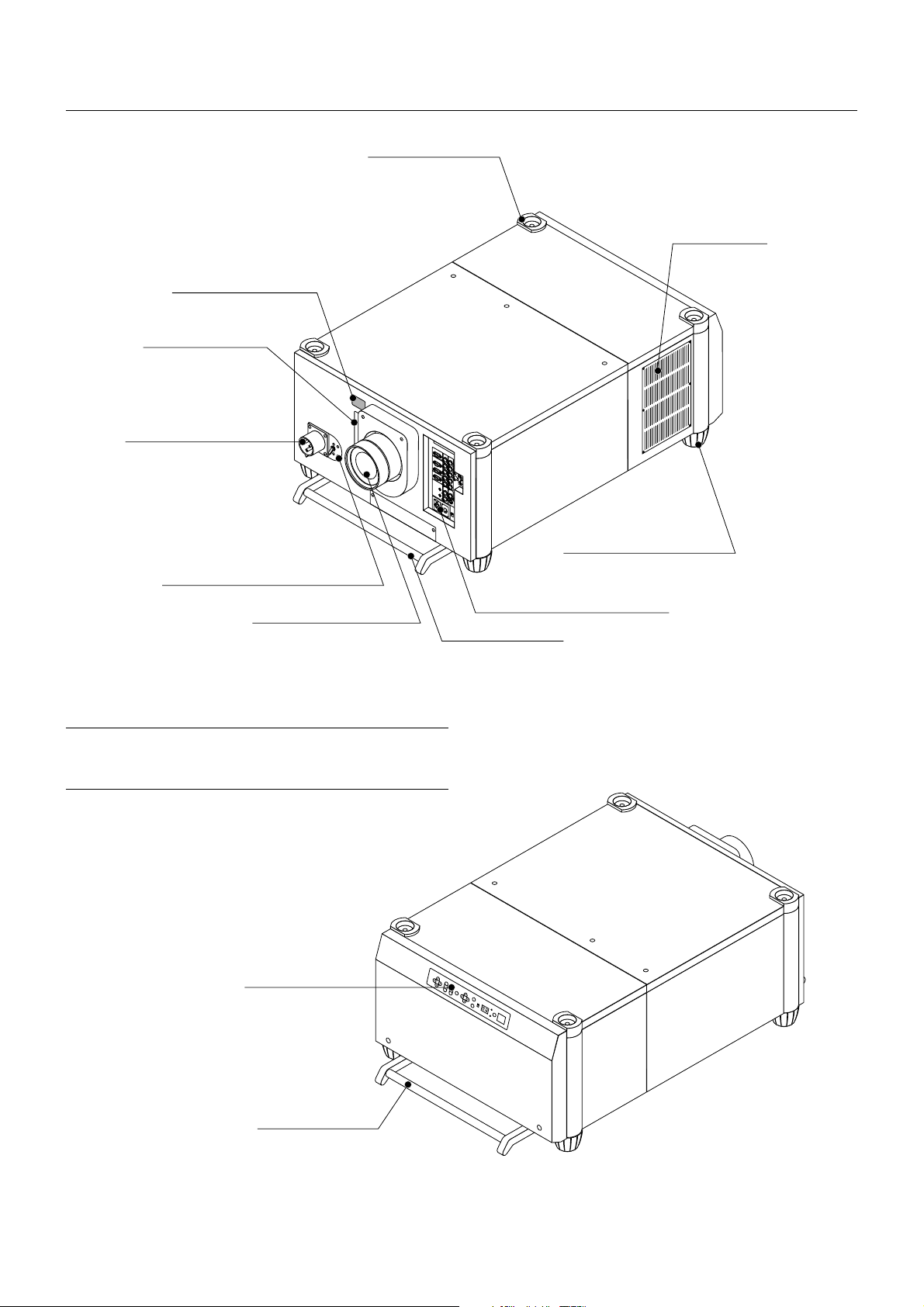
Projector
PC Card Slot
Insert a PC memory card
here to upgrade the
projector system software
or copy data. To access
the slot, loosen the screw.
AC INPUT
Connect the supplied power
cable here (AC 200-240V).
Stacking Pad (4 pcs)
Ventilation (out)
Remote Sensor
Foot
Power Switch (Main power)*
Lens (Optional)
*To turn on the main power to the projector, press the s witch to the ON
position (I) and the POWER indicator on the rear panel will turn orange in color.
Press to the OFF position (0) to turn the main power off.
NOTE: When turning off the main power, first return the projector to the standby
condition by pressing the POWER OFF button on the remote control or the POWER
button on the rear panel and then turn off the main POWER switch. These procedures are necessary to protect your projector and the connected equipment.
Controls
Input Terminal Panel
Carrying Handle
Carrying Handle
E – 2
Page 9
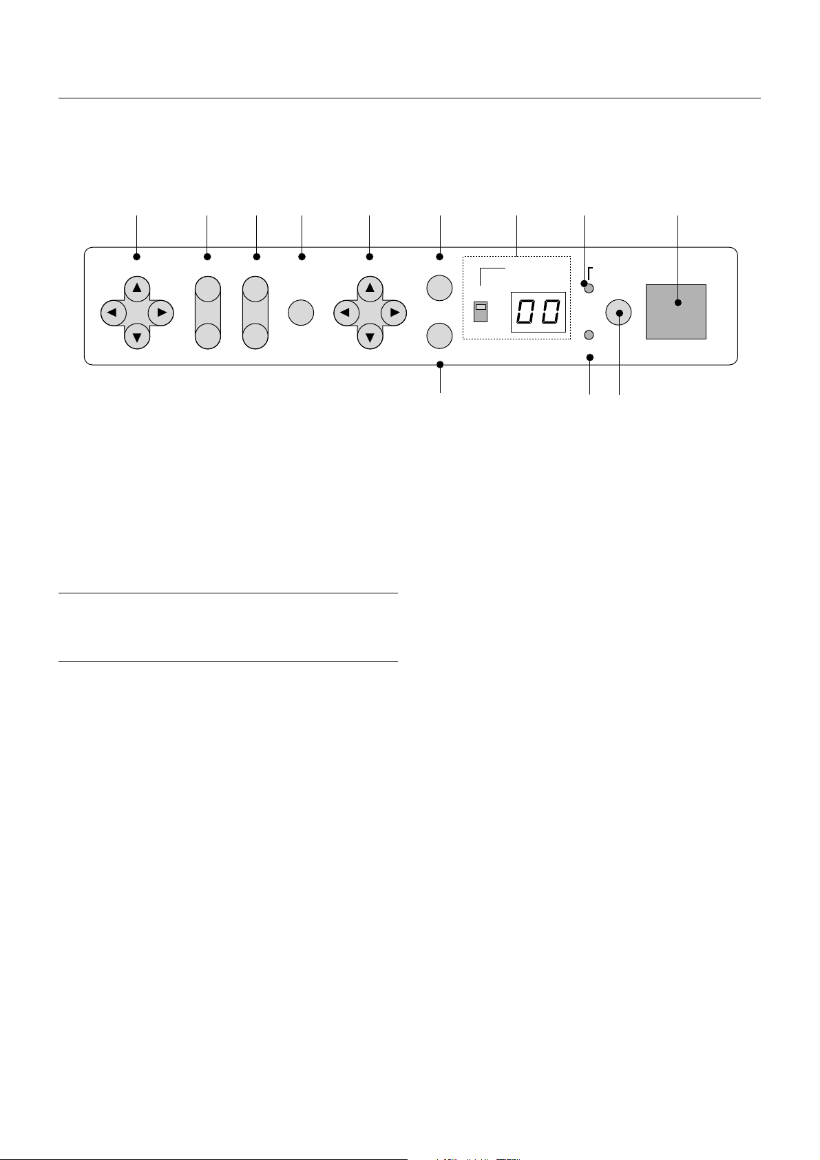
Controls
11 10 9 8 7 5 4 2
LENS SHIFT
1. Power Button
Press to turn the projector on when the projector is in the standby condition (Main Power switch must be on and the POWER indicator lit orange). Press and hold for 2 seconds to turn off the projector.
2. Power Indicator
When this indicator is green, the projector is on; when the indicator is
orange, it is in standby mode.
NOTE: After the projector is turned off, the indicator "--" flashes for three minutes to show that the cooling fan is working.
Do not turn off the main power during that time. After "--" stops flashing, the
POWER indicator will change to a steady orange glow and the projector will be
in the stand-by mode.
3. Status Indicator
When the On Timer is set and the projector is in the standby mode , the
Status indicator flashes green to show that the On Timer program is
active.
4. Two Digit Display
During normal operation the current projector ID (address) is shown in
this two digit display. In the event of an error, a projector error code will
be displayed. The display can be turned off using the ON/OFF Switch to
the left of the display.
FOCUS
ZOOM MENU SELECT
-
Remote sensor
ENTER
INDICATOR POWER
ON
ON/OFF
+
OFF
CANCEL
STATUS
136
6. Cancel Button
Press this button to exit the menu. Press this b utton to return the adjustments to the last condition while you are in the adjustment or setting
menu.
7. Select (Up/Down/Left/Right) Button
Up/Down: Use these b uttons to select the menu of the item y ou wish to
adjust.
Left/Right: Use these buttons to change the level of a selected menu
item.
8. Menu Button
Displays the main menu for operation.
9. Zoom Button
Zoom the lens in and out.
10. Focus Button
Adjust the lens focus.
11. Lens Shift Button
Adjust the lens offset by shifting the projected image position horizontally and vertically.
5. Enter Button
Executes your menu selection and activates items selected from the
menu. When the slidebar or dialog box is displayed:
Pressing this button confirms adjustments/setting and returns to the
previous menu display.
E – 3
Page 10
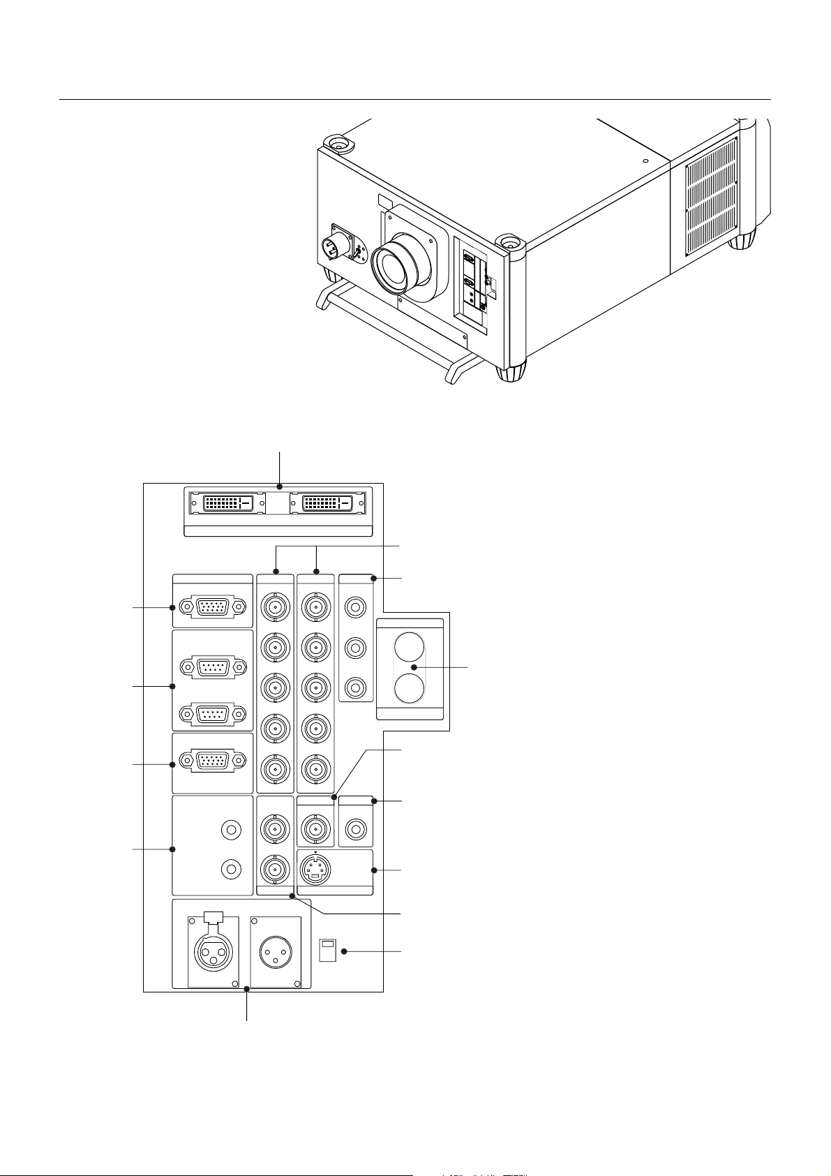
Terminal Panel
5
OUTPUT
RGB DIGITAL
INPUT9
6
INPUT3
RGB
INPUT2 INPUT1 INPUT4
R/Cr
R/Cr Cr
7
1
OPTION
IN
2
OUT
REMOTE1
G/Y G/Y
B/Cb
B/Cb
H/HVVVH/HV
Cb
OUTPUT
Y
SDI
INPUT0
8
3
Y
C
INPUT7
IN
INPUT5 INPUT6
VIDEO1 VIDEO2
S-VIDEO2
INPUT8
LED
ON
OFF
9
10
11
12
REMOTE2
IN
S-VIDEO1
4
OUT
REMOTE3
OUT
13
E – 4
Page 11

1. INPUT 3 RGB Connector (Mini D-Sub 15 pin)
Connect your PC or other analog RGB equipment such as a high-definition document camera.
This connector accepts RGB signals only.
Not compatible with component signals.
2. Option Connector (Mini D-Sub 9 pin)
For system expansion such as PC-control.
IN ................. connect to the external equipment such as PC or Third Party
Control System.
OUT ............. for daisy-chaining multiple projectors and operating them with
the same external equipment. To do so, connect to a second
projector's IN terminal to relay the input at the IN terminal of
the first projector until all the projectors are connected.
3. REMOTE 1 Connector (Mini D-Sub 15 pin)
This terminal allows external control of the projector from either the
Switcher or from an external control. When the Switcher is used, connect to the REMOTE 1 terminal on the back of the Switcher.
NOTE: This projector is compatible with the ISS-6020 Switcher.
4. REMOTE 2 Jacks
IN ................. wired remote control input.
OUT ............. for daisy-chaining multiple projectors and operating them with
the same remote control. To do so, connect to a second projector' s IN terminal to relay the input at the IN terminal of the
first projector until all the projectors are connected.
5. RGB Digital Input/Output Connectors (DVI-D 24 pin)
These connectors are used for double stacking.
Use the supplied DVI-D cable to connect the OUTPUT terminal of the
first projector to the second projector's INPUT until all the projectors
are connected.
The output is TMDS non-perfect.
The output connector is used for stacking.
7. INPUT 4 Y/Cb/Cr Terminal (RCA)
Connect component video outputs (Y/Cb/Cr, Y/Pb/Pr) of the external
equipment such as DVD player.
NOTE: This terminal accepts component signals only.
8. INPUT 5 VIDEO 1 Terminal (BNC)
Connect to the BNC video output of the external equipment such as a
VCR or laser disc player.
9. INPUT 6 VIDEO 2 Terminal (RCA)
Connect to the RCA video output of the external equipment such as a
VCR or laser disc player.
10. INPUT 8 S-VIDEO 2 Terminal (Mini DIN 4 pin)
Connect to the S-video output of the external equipment such as a
VCR with an S-video output. This terminal allows switching betw een S2
and S1 VIDEO input modes. See the "S-Video Mode Select" section on
page E-38 for more information.
11. INPUT 7 S-VIDEO 1 Terminal (BNC)
Connect to the Y/C separate BNC video outputs of the external equipment such as a VCR or laser disc pla yer.
12. LED Switch
Lights up the panel on both the front and the rear at the same time.
13. REMOTE3 Connectors (XLR Connectors)
Connect an extension cable such as an audio cable to control two projectors or more using the remote control. See page E-43 for the pin
assignments.
IN ................. wired remote control input.
OUT ............. for daisy-chaining multiple projectors and operating them with
the same remote control. To do so, connect to a second projector's IN terminal to relay the input at the IN terminal of the
first projector until all the projectors are connected.
6. INPUT 1 and INPUT 2 Terminals (BNC)
Connect R,G,B,H (Horizontal sync) and V (Vertical sync) outputs of the
external equipment such as the Switcher. If using a component with a
combined sync (SYNC) output, connect it to the H/V terminal.
Also connect component video outputs (Y/Cb/Cr) of the external equipment such as DVD player.
NOTE: The INPUT 2 terminal does not support SW1 Level and SW2 Level modes
for the ISS-6020 switcher.
E – 5
Page 12
7
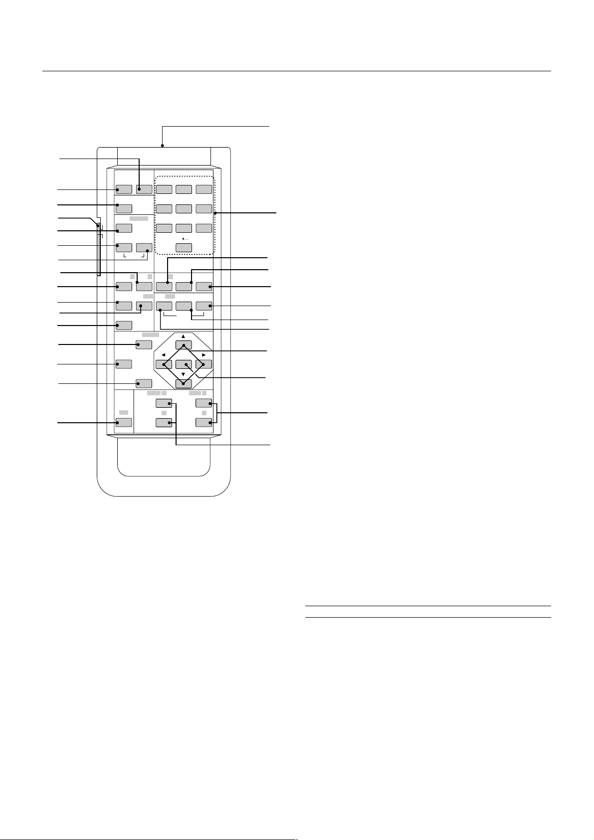
Remote Control
Remote Control Features
2
POWER INPUT
13
28
22
21
15
17
16
10
11
26
1
ON
TEST
PROJECTOR
IMAGE/
8
7
6
ON
PICTURE
OFF
ADJUST
R
KEY ST./
PIXEL SOUND
AUTO
MENU/
3
UNDO
CTL
OFF
WHITE BAL.
G
AMP
/
LENS
POSI/
ADDRESS
CANCEL
FOCUS
ABC1DEF2GHI
JKL4MNO5PQR
STU7VWX
E-LIST/
PICT/
+
-
B
SHUT
MAGNIFY/
8
0
HELP
MUTE
ENTER
ZOOM
3
6
9
INFO
OSD
7 ADJUST PICTURE
Press to display the Picture adjustment screen. Pressing this button
sequentially selects "Brightness" → "Contrast" → "Saturation" → "Color"
→ "Hue" → "Sharpness" → "V-Aperture" → "Gamma Correction".
2
8 IMAGE/PROJECTOR
Press to display the Image Option screen. Pressing this button sequentially selects "Pixel Adjust" → "Position" → "Aspect Ratio" → "Resolu-
tion" → "Overscan" → "Video Filter" → "Blanking".
While pressing and holding CTL, pressing this button rotates "On/Off
Timer" → "Sleep Timer" → "Menu" → "Setup" → "Link Mode" →
"Switcher Control".
9 INPUT
23
14
12
19
18
20
5
4
25
24
9
Use to select an input, to name a signal, or to enter a passcode during
input registration.
1--INPUT 1 for RGBHV/Y, Cb/Pb, Cr/Pr
2--INPUT 2 for RGBHV/Y, Cb/Pb, Cr/Pr
3--INPUT 3 for RGB
4--INPUT 4 for Y, Cb/Pb, Cr/Pr
5--INPUT 5 for VIDEO 1
6--INPUT 6 for VIDEO 2
7--INPUT 7 for S-VIDEO 1
8--INPUT 8 for S-VIDEO 2
9--INPUT 9 for RGB DIGITAL input
0--INPUT 0 for SDI input on the optional SDI board
10 UNDO
Press to return the adjustments and settings to the previous condition.
While pressing and holding CTL, pressing this button clears all the menus
or adjustment/setting screen. At this time the adjustments/settings are
stored in memory.
11 CANCEL
Press to exit the menu.
Press this button with CTL to return to the previous menu while the
menus appear. This feature allows you to adjust several items concurrently.
12 INFO
Displays the "Source Information" or "Projector Information" window.
This button toggles between these two windows.
YZ/
+
-
1 POWER ON
Press to turn on the projector. The POWER indicator lights up green.
2 POWER OFF
Press and hold this button for a minimum of two seconds to turn off the
projector.
3 MENU
Press to display the main menu.
While pressing and holding CTL, press this button to display the Remote Control ID dialog box to specify the remote control ID.
4 ENTER
Executes the menu selection and activates items selected from the menu.
When the slidebar or dialog box is displayed:
Pressing this button confirms adjustments/setting and returns to the
previous menu display.
5 SELECT (Up/Down/Left/Right)
When pressed together, the CTL and 䊴 buttons work as a Back Space
key in the entry screen.
Pressing and holding CTL, then this button moves the menu, slidebar
or dialog box.
6 ADJUST WHITE BAL
Press to display the Color adjustment screen. Pressing this button sequentially selects "Color Temperature" → "White Balance - Brightness"
→ "White Balance - Contrast" → "Signal Level" → "Ref.White Bal" →
"Switcher-Gain".
13 TEST
Press to display the test pattern. Pressing this button sequentially selects five test patterns.
14 HELP
Provides online help.
15 PIXEL
Displays the Pixel Adjust screen to adjust the clock and phase.
16 AUTO (RGB only)
Press to adjust Position-H/V and Pixel Clock for an optimal picture.
NOTE: The Pixel Phase is not available.
17 POSITION
Press to display the Blanking screen; press again to display the Position screen.
While pressing and holding CTL, pressing this button displays the Lens
Shift adjustment screen.
18 MUTE SOUND
(available only when using with the ISS -6020 or IPS4000)
Turns off the sound for a short period of time. Press again to restore the
sound.
E – 6
Page 13
19 MUTE OSD
S
M
Press to turn off the on-screen display. Press again to restore the onscreen display .
NOTE: You can also turn off the on-screen display by pressing and holding CTL
and then pressing MUTE OSD; doing this again restores it. In this case any
adjustment will still change the projector's memory settings. This mode is available even when an input is switched to another or the power is turned off using
the POWER OFF button on the remote control.
20 MUTE PICTURE
Press to turn off the picture for a short period of time. Press again to
restore the picture. Pressing and holding CTL, then pressing this b utton
shuts off the light completely .
NOTE: This is also considered the LENS SHUTTER.
21 KEYSTONE (R)
Press to display the Keystone Correction screen.
22 AMPLITUDE (G)
Service personnel only.
23 ENTRY LIST (B)
Press to display the Entry List screen.
24 FOCUS (+/–)
While pressing and holding CTL, pressing this button allows you to adjust the lens focus.
Remote Control Precautions
• Use the remote control within a distance of about 7m (23feet) and at
an angle of 30˚ above, below , to the left and to the right of the remote
control sensor located at the front of the main unit.
• The remote control system may not function when direct sunlight or
strong illumination strikes the remote control sensor of the main unit,
or when there is an obstacle in the path.
• When remote control buttons are pressed and held, main unit function keys may not operate.
• Do not subject to strong shock.
• Do not allow water or other liquid to splash on the remote control. If
the remote control gets wet, wipe it dry immediately.
•Avoid exposure to heat and steam.
• Remove the batteries from the remote control when the remote control is not going to be used for a long period.
You cannot operate the projector using the remote control if:
• the remote ID is not set to [00].
• the remote ID is not the same as the projector ID.
See page E-23 for setting remote ID and page E-39 for setting projector ID.
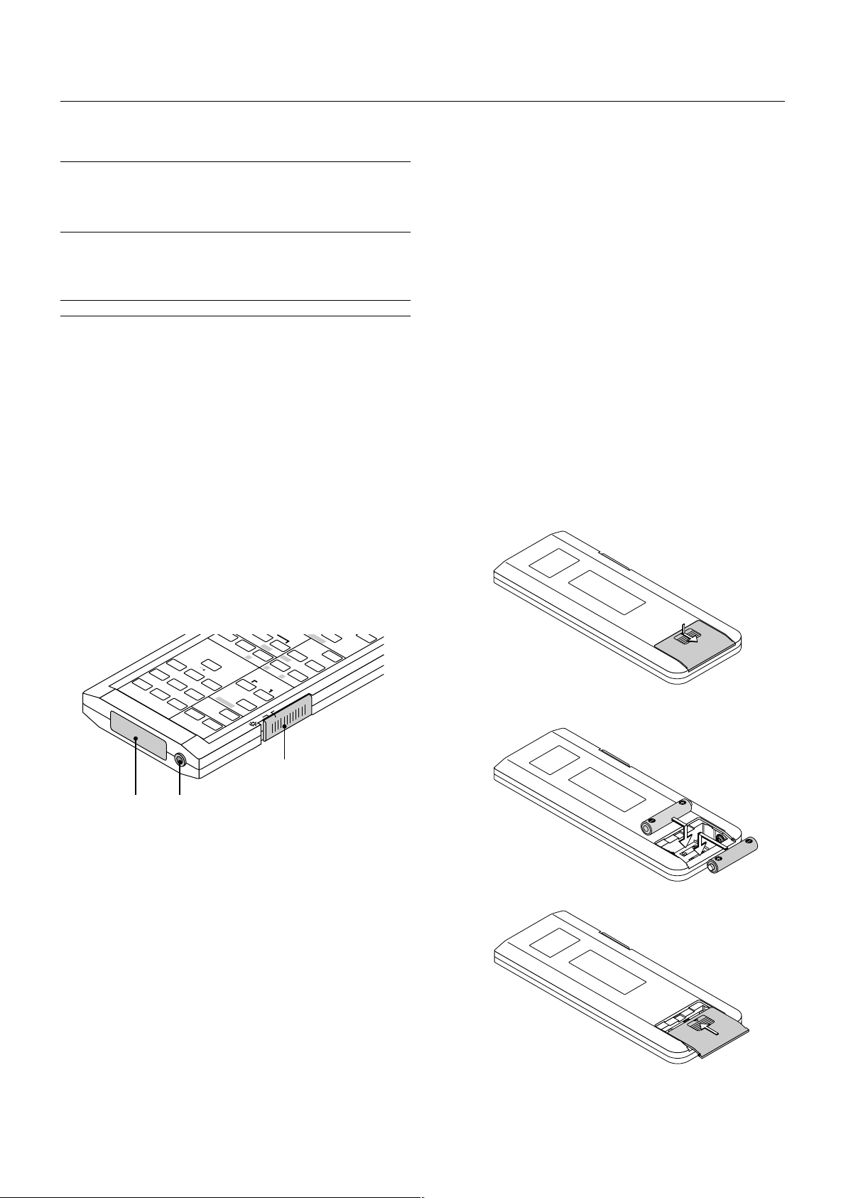
Remote Control Battery Installation
Installing the Remote Control Batteries
When it comes time to replace the batteries, two "AA" type will be required.
25 MAGNIFY/ZOOM (+/–)
Magnify the size of a target portion.
While pressing and holding CTL, pressing this button allows you to zoom
the lens in and out.
26 CTL
Used in conjunction with other buttons, similar to a shift key on a computer.
S
D
N
U
O
INFO
S
T
U
H
S
HELP
B
E-LIST/
G
WHITE BAL.
PROJECTOR
IMAGE/
/
P
ADJUST
PICTURE
ON
YZ/
9
PQR
6
GHI
3
DEF
2
INPUT
0
VWX
8
STU
MNO
7
5
JKL
4
ABC
1
OFF
TEST
ON
POWER
E
R
D
D
A
UNDO
PICT/
S
N
E
L
M
A
R
FF
O
MENU/
AUTO
POSI/
L
E
IX
P
KEY ST./
28
29 27
27 Remote Jack
Connect your remote control cable here for wired operation.
28 Backlight Switch
When using the remote control wirelessly:
Turns the backlight on and off. If no button operation is made within 30
seconds with the Backlight ON, the Backlight will turn off to conserve
battery life.
When using as the wired remote control:
The light stays on in standby and power-on.
1. Press and open the cover.
2. Align and insert the batteries according to the (+) and (-) indications
inside the case.
3. Replace the cover.
29 Infrared Transmitter
Direct the remote control toward the remote sensor on the projector
cabinet.
E – 7
Page 14
2. INSTALLATION
This section describes how to set up your projector and how to connect
video and audio sources.
Setting Up Your Projector
Your Projector is simple to set up and use. But before you get started,
you must first:
1. Determine the image size
2. Set up a screen or select a non-glossy white wall onto which you can
project your image.
3. Install the optional lens to the projector.
NOTE: The lens must be installed by service personnel only.
4. Connect the supplied power cable.
5. Set up the projector.
6. Connect a PC, VCR, DVD player, or other equipment.
7. Make settings or adjustments on the projector.
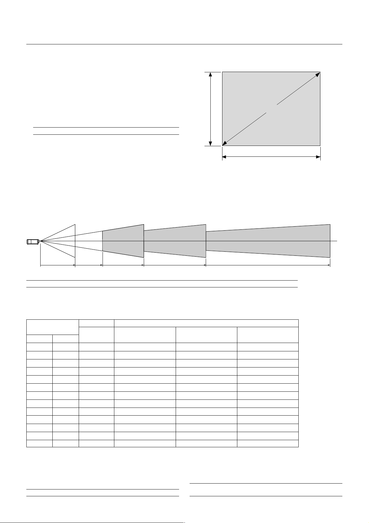
Throw Distance
Screen Size and Projection Distance
Applicable lens and throw distance/ List of screen sizes
Height
(V)
Formulas: Screen Width H (5:4) (m) = Screen Height V x 5/4 x 0.0254
Screen Height V (5:4) (m) = Screen Width H x 4/5 x 0.0254
Screen Diagonal (5:4) (m) = Screen Height V x 6.4/4 x 0.0254
Screen Width H (5:4) (inch) = Screen Height V x 5/4
Screen Height V (5:4) (inch) = Screen Width H x 4/5
Screen Diagonal (5:4) (inch) = Screen Height V x 6.4/4
Screen size (Diagonal)
Width (H)
TL-2Z (H x 2.5) – (H x 4.0)
TL-08SF (H x 0.84)
NOTE: Image has 5:4 aspect ratio. Take this into account when specifying a screen.
TL-1ZH (H x 1.5) – (H x 2.5)
Table of Throw Distances and Image Sizes for Optional Lenses
Screen Size (5:4)
Width (H)
1.6(63)
1.9(75)
2.3(90)
2.9(112.5)
3.4(135)
4.0(157.5)
4.6(180)
5.1(202.5)
5.7(225)
6.7(262.5)
7.6(300)
8.6(337.5)
9.5(375)
For screen sizes between 80” and 500” not indicated on the above table, use formulas below.
Projection Distance = Screen Width (H) x Lens Magnification
Throw distance for TL-08SF (LA00111)lens =H x 0.84
Throw distance for TL- 1ZH (LA00263) lens =H x 1.5 - H x 2.5
Throw distance for TL- 2Z (LA00108)lens =H x 2.5 - H x 4.0
Throw distance for TL- 4Z (LA00109) lens =H x 4.0 - H x 7.0
NOTE: Distances may vary +/- 5%.
Height (V)
1.2(50.4)
1.5(60)
1.8(72)
2.3(90)
2.7(108)
3.2(126)
3.7(144)
4.1(162)
4.6(180)
5.3(210)
6.1(240)
6.9(270)
7.6(300)
SF Fixed Lens
TL-08SF
0.84:1
1.3(52.9)
1.6(63)
1.9(75.6)
2.4(94.5)
2.9(113.4)
3.4(132.3)
3.8(151.2)
4.3(170.1)
4.8(189)
5.6(220.5)
6.4(252)
7.2(283.5)
8.0(315)
TL-1ZH
1.5-2.5
2.4(94.5) - 4.0(157.5)
2.9(112.5) - 4.8(187.5)
3.4(135) - 5.7(225)
4.3(168.8) - 7.1(281.3)
5.1(202.5) - 8.6(337.5)
6.0(236.3) - 10.0(393.8)
6.9(270) - 11.4(450)
7.7(303.8) - 12.9(506.3)
8.6(337.5) - 14.3(562.5)
10.0(393.8) - 16.7(656.3)
11.4(450) - 19.1(750)
12.9(506.3) - 21.4(843.8)
14.3(562.5) - 23.8(937.5)
Zoom Lens
TL-2Z
2.5 - 4.0
4.0(157.5) - 6.4(252)
4.8(187.5) - 7.6(300)
5.7(225) - 9.1(360)
7.1(281.3) - 11.4(450)
8.6(337.5) - 13.7(540)
10.0(393.8) - 16.0(630)
11.4(450) - 18.3(720)
12.9(506.3) - 20.6(810)
14.3(562.5) - 22.9(900)
16.7(656.3) - 26.7(1050)
19.1(750) - 30.5(1200)
21.4(843.8) - 34.3(1350)
23.8(937.5) - 38.1(1500)
NOTE: Do not use another optional lens TL-1Z on THUNDER 10000sx.
Doing so will not deliver the performance of the projector.
TL-4Z (H x 4.0) – (H x 7.0)
Unit: m (inch)
TL-4Z
4.0-7.0
6.4(252) - 11.2(441)
7.6(300) - 13.3(525)
9.1(360) - 16.0(630)
11.4(450) - 20.0(787.5)
13.7(540) - 24.0(945)
16.0(630) - 28.0(1102.5)
18.3(720) - 32.0(1260)
20.6(810) - 36.0(1417.5)
22.9(900) - 40.0(1575)
26.7(1050) - 46.7(1837.5)
30.5(1200) - 53.3(2100)
34.3(1350) - 60.0(2362.5)
38.1(1500) - 66.7(2625)
E – 8
Page 15
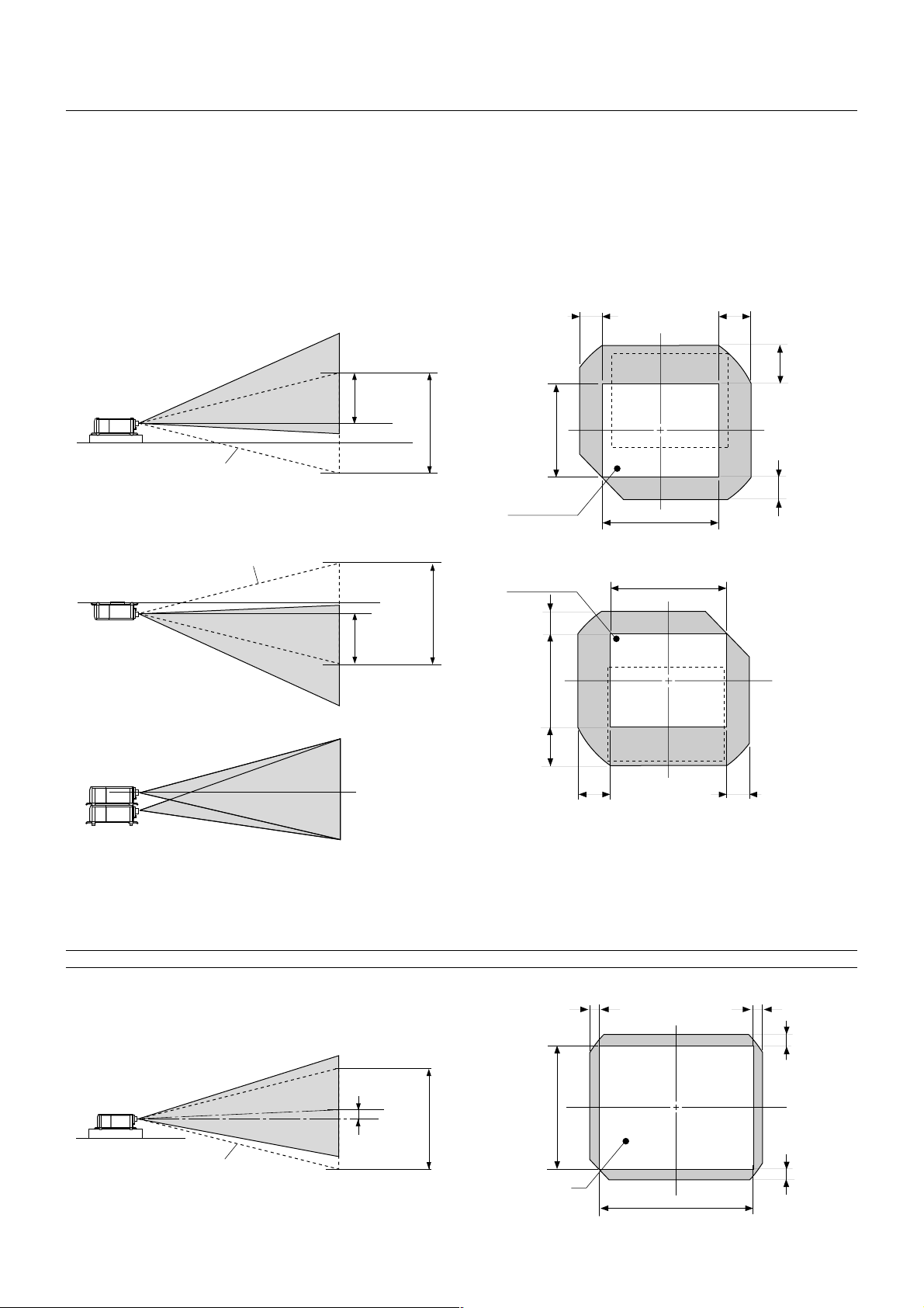
Lens Shift Adjustable Range
Lens Shift Adjustable Range for Desktop and Ceiling Mount Application
The diagram below shows the location of the image position in the lens. The lens can be shifted within the shaded area as sho wn using the normal
projection position as a starting point.
Maximum Possible Range for TL-1ZH, TL-2Z and TL-4Z
Parenthesized values for the ceiling mount application
Up: 0.41 V (0.24 V) Right: 0.28 H (0.19 H)
Down: 0.24 V (0.41 V) Left: 0.19 H (0.28 H)
(H: width of projected image, V: height of projected image)
Desktop/ Front
Vertical
Max. 0.41V
1V
(V)
0.19H
0.28H
0.41V
Normal position
Normal Projection
position
Ceiling/ Front
Vertical
Example for Stack
Normal position
Max. 0.41V
Screen center
Normal Projection
position
1V
0.24V
(V)
0.41V
0.28H
(H)
(H)
0.19H
Fixed Lens TL-08SF
Maximum Possible Range for TL-08SF
Up: 0.09 V Right: 0.06 H
Down: 0.09 V Left: 0.06 H
(H: width of projected image, V: height of projected image)
NOTE: To reduce the distortion of an image, it is recommended that the projector is horizontally positioned at a projection angle of 0 degree.
0.24V
Normal position
Max. 0.09V
1V
Normal Projection
position
E – 9
(V)
0.06H
0.06H
0.09V
0.09V
(H)
Page 16
Moving The Projector
Always carry your projector by the handle. Ensure that the power cable
and any other cables connecting to video sources are disconnected
and the lens is removed from the projector before mo ving the projector .
When moving the projector or when it is not in use, cover the lens with
the lens cap.
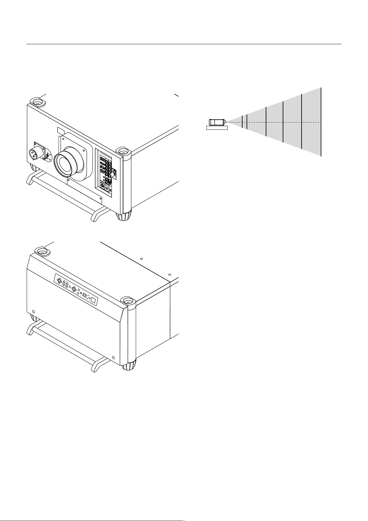
Selecting A Location
The further your projector is from the screen or wall, the larger the image. The minimum size the image can be projected is 80" (2 m) measured diagonally. The largest the image can be is 500" (12.7 m).
500"
400"
300"
200"
100"
80"
WARNING
• Only use your projector on a solid, level surface. If the projector falls
to the ground, you can be injured and the projector severely damaged.
• Do not use the projector where temperatures vary greatly. The projector must be used at temperatures between 40 degrees F (5 degree C) and 95 degrees F (35 degree C).
• Do not expose the projector to moisture, dust, or smoke. This will
degrade the screen image.
• Ensure that you have adequate ventilation around your projector for
proper heat dissipation. Do not cov er the v ents on the projector cabinet.
E – 10
Page 17
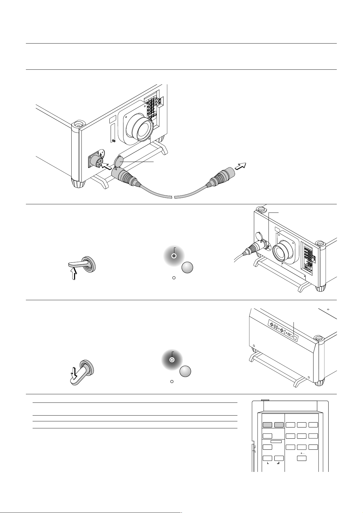
3. SETUP
Connecting the Power Cable and Turning on the Projector
Before you turn on your projector, ensure that the computer or video source is turned on and that your lens cap is removed.
1. Connect the supplied power cable to the projector.
Plug the supplied power cable into the AC outlet.
Open the cover of the
power cable to plug
fully into the AC IN on
the projector.
Note:
Projector power connector may vary depending upon country.
Currently USA model will be a “Twist-lock” and European model
will be a “C-form”.
To the wall outlet
2. Turn On The Projector
The main power switch is on the front panel of the projector.
By pushing up this switch, the projector will go into its standby mode and the POWER
indicator will glow orange. Only after you press the 'POWER ON' button on the remote
control or projector cabinet will the POWER indicator turn to green and the projector
will fully turn on.
ON
POWER
ON/OFF
POWER
OFF
STATUS
3. Turn Off The Projector
First press the POWER OFF button on the remote control or the projector cabinet for a minimum of two seconds. Allow the fan to cool the projector for three minutes.
This will extend the life of the lamp. After the cooling fan stops working, the POWER indicator
will change to a steady orange glow and the projector will be in the stand-by mode. Then turn
off the main power switch on the fr ont panel. The PO WER indicator will go out. If you desire to
move the projector then unplug the power cable.
ON
POWER
ON/OFF
POWER
OFF
STATUS
[POWER] switch
[POWER] button
[POWER] indicator
NOTE: Immediately after turning on the projector, screen flicker may occur. This is not a fault. Wait 3 to 5
minutes until the lamp lighting is stabilized.
CAUTION: Do not turn off the main power while the cooling fan is working.
E – 11
POWER INPUT
ON
TEST
PROJECTOR
IMAGE/
ON
PICTURE
OFF
WHITE BAL.
ADJUST
OFF
ABC1DEF2GHI
JKL4MNO5PQR
STU7VWX
3
6
8
YZ/
9
0
Page 18

About Startup Screen
ENTER
CANCEL
UNDO
AUTO
HELP
ON
TEST
ABC1DEF2GHI
3
JKL4MNO5PQR
6
STU7VWX
8
0
YZ/
9
POWER INPUT
OFF
INFO
PIXEL SOUND
OSD
MAGNIFY/
CTL
FOCUS
+
-
ZOOM
+
MENU/
ADDRESS
IMAGE/
PROJECTOR
POSI/
LENS
KEY ST./
ON
OFF
R
E-LIST/
PICTURE
ADJUST
WHITE BAL.
B
AMP
/
G
PICT/
SHUT
-
MUTE
(Menu Language Select screen)
When you first turn on the projector, you will get the Startup screen.
This screen gives you the opportunity to select one of the seven menu languages: English, German,
French, Italian, Spanish,Swedish and Japanese.
To select a menu language, follow these steps:
1. Use the Select ▲ or ▼ button to select one of the seven languages for the menu.
ENTER
2. Press the Enter button to execute the selection.
3. The Basic/Custom menu will be displayed in the language you
To close the menu, press the Cancel button.
After this has been done, you can proceed to the advanced menu operation.
If you want, you can select the menu language later. See "Language" on page E-37.
have selected.
ENTER
CANCEL
E – 12
Page 19

Set up the projector
1. Turn on the projector
2. Select your type of projection:
Desktop front, ceiling rear, desktop rear, and ceiling front.
(2) Press and hold the CTL and press the ZOOM + or - button to adjust the
image size optically. You can also adjust the image size by using the ZOOM
+ or - button on the projector cabinet.
The zoom function processes a signal digitally. For this reason, the zoom
buttons on the remote control and the projector cabinet are not available
for HDTV, Video, S-Video, and SDI signals.
FOCUS
+
MAGNIFY/
ZOOM
+
3. Display the test pattern by pressing the TEST button on the remote control or using the menu.
TEST
4. Adjust the image position and the image size.
(1) Press and hold the CTL button and press the POSITION button to display
the Lens Shift adjustment screen.
Use the Select button on the remote control or the LENS SHIFT button on
the projector cabinet to move the image horizontally and vertically.
To close the Lens Shift adjustment screen, press the CANCEL button.
See page E-9 for “Lens Shift Adjustable Range”.
LENS
POSI/
CTL
(3) Press and hold the CTL button and press the FOCUS + or - button to
obtain the best focus optically. You can also adjust the focus by using the
FOCUS + or - button on the projector cabinet.
-
-
ENTER
CTL
CTL
FOCUS
+
-
MAGNIFY/
ZOOM
+
-
E – 13
Page 20

Keystone
2) Hookup
2-1. Use the supplied DVI-D cable to connect the RGB DIGITAL output
of the master projector to the RGB DIGITAL input (INPUT9 ) of the
slave projector until all the projectors are connected.
Keystone distortion
Keystone is the distortion of a projected image that usually creates a
wider top than bottom. Aiming a projector upward on a w all rather than
straight at a wall creates this distortion. Use the 䊴 or 䊳 buttons on the
slide bar to correct this keystone (trapezoidal) distortion.
Normal
NOTE: The keystone feature is not available when the test pattern or the blue
background is displayed.
NOTE: With the projector aimed directly at the screen the maximum keystone
angle that can be corrected is +/- 7.5 degrees.
Setting up for Double Stacking in Link Mode
2-2. Next, using a commercially a vailab le, bi-directional RS-232C cable
connect the OPTION OUT terminal of the master projector to the
OPTION IN terminal of the slave projector until all the projectors are
connected.
2-3. Turn all the projectors on and roughly make some optical adjust-
ments to each projector.
3) Adjusting and registering signals to be projected in Link mode
and stack application.
Signal Data Preparation
3-1. Create data for the master projector and copy data to the slave
projector.
3-1-1. Choose one projector as the master.
3-1-2. Turn the master projector on.
3-1-3. Display all desired input signals, make adjustment to each
signal, then save all adjustments on the master projector. (Ad-
justments will be saved automatically.)
3-1-4. Turn the master projector off (standby mode).
3-1-5. Store all the adjustments on a PC card from the master pro-
jector.
3-1-5-1. Open the PC Card slot cov er to access the PC card slot.
Insert a PC card into this slot.
NOTE: DO NOT TURN OFF THE POWER while the PC Card Access indicator
is flashing. Doing so will cause damage to the data of the projector system.
CAUTION: To prevent the projectors from falling, install them in a place and
fasten them in a way with sufficient strength to support the two projectors.
NOTE: SW 1 Level and SW 2 Level of Switcher Control are not available in Link
Mode.
1) Stacking the Projectors
1-1. Place the projectors at the proper height for best screen to projec-
tor relationship. Mak e sure that all projectors ha ve the same display
orientation.
NOTE: Back up your data if you use the supplied CompactFlash card to copy
the data from the master projector to the slave projector. The supplied
CompactFlash card contains data and firmware for factory use.
3-1-5-2. Press and hold CANCEL, then press POWER on the
rear panel of the master projector. The POWER indicator will
change to steady green and the PC Card Access indicator
will start flashing. After storing data on the PC card, the
POWER indicator will change to orange.
3-1-5-3. Remove the PC card from the slot of the master projec-
tor.
3-1-6. Transfer the data to the slave projector using the PC card so
that all the projectors have the same data in memory.
3-1-6-1. Insert the PC card into the slot of a slave projector.
NOTE: Since data in the slave projector will be lost at this time, make backup
copies of them before proceeding.
3-1-6-2. Press and hold ENTER, then press MENU on the rear
panel of the slave projector . The PO WER indicator will change
to steady green and the PC Card Access indicator will start
flashing to indicate that the data is being copied from the PC
card to the slave projector. After copying data to the slave
projector, the POWER indicator will change to orange.
E – 14
Page 21

3-1-6-3. Remove the PC card from the slave projector.
6-4-1. Display any signal onto the screen.
NOTE: If you select the RGB1 input on the master projector, you must select
the same input on the slave projector. The same applies to the RGB2 input.
NOTE: After adjusting and registering signals as mentioned above, you must
change the input to RGB on the Entry Edit Command window for Link Mode.
See "Entry List Edit" on page E-31 for changing to RGB source.
3-1-6-4. Display the desired source.
4) Display the internal crosshatch test pattern.
NOTE: Use a different single color for each projector.
Example:
Turn on Green of one projector (master), then Red of the other (slave).
5) Adjusting the lens shift, zoom and focus to clearly display
all projected patterns.
5-1. Adjust the Lens Shift using the LENS SHIFT button on the projec-
tor cabinet. You can also adjust the Lens Shift by pressing and holding CTL and pressing the POSITION button on the remote control.
For Lens Shift Adjustable Range, see page E-9.
5-2. Zoom the lens in and out by using the ZOOM b utton on the projec-
tor cabinet or the remote control.
5-3. Adjust the lens focus by using the FOCUS button on the projector
cabinet or the remote control.
NOTE: If the physical (vertical) alignment of the projector is not correct,
adjust the height of the feet. If there is any keystone distortion, use Keystone
adjustment to correct and save the settings on each projector. See page E14 and E-35 for Keystone correction. See page E-39 for Keystone save. This
completes set-up and adjustments. An image is projected from the master
projector. See page E-39 for Link mode.
6) Link Mode Setting
6-4-2. Check to see if the images on the master projector are dis-
played in synchronization with the ones on the other slave pro-
jector while the projectors are in link mode.
NOTE: Registering signals is not possible in the Link mode. To register a
signal, first set "Link Mode" to "Standalone" on the menu and then repeat the
above steps from 3. If you select an unregistered signal, the master projector displays the image, but the slave projector doesn't. To view the information on the currently displayed signal, select [Help] → [Source Information].
6-5 Make adjustments to the slave projector.
NOTE: See “List of Menu Items Available on Link Mode” on page E-45 for
more information.
6-5-1. Temporarily, change the master projector from Master to
Standalone.
Make sure that the slave projector is still in Slave mode.
6-5-2. Displa y a source you want to adjust from the master projector .
6-5-3. On the Slav e Projector select the same signal F rom the Entry
List (same No.) as that of the master projector . Display it from the
slave projector.
6-5-4. Make Picture adjustment such as brightness, contr ast, or color
temperature.
6-5-5. Change the master projector from Standalone to Master to
activate the Link Mode
6-6 This completes the Link Mode adjustment procedure.
NOTE: When the Link mode is enabled, be sure to turn on the master projector
first and then the slave projector.
If you fail to do this, the slave projector will not work correctly.
Once you have turned on the master projector, the slave projector will automatically be turned on.
6-1 Assign a unique Projector ID for each projector.
6-1-1. Select [Projector Options] →[Setup] →[Page 5] →[Projector
ID]. See page E-39 for specifying ID.
6-1-2. Specify a unique projector ID for each projector.
6-2 Select the same communication speed for all the projectors.
6-2-1. Select [Projector Options] →[Setup] →[Page 5]
→[Communication Speed]. See page E-39 for setting the communication speed.
6-2-2. Select the appropriate speed between 4800 and 38400.
6-3 Set the Link Mode on each projector.
6-3-1. Select [Projector Options] →[Link Mode].
6-3-2. First select [Slave] on the slave projector.
6-3-3. Select [Master] on the master projector. See page E-39 for
setting Link Mode.
6-4 Project a source image from all projectors
NOTE: In the Link mode the Lens Memory feature is not available.
E – 15
Page 22

Projector Orientation
An image can be projected from in front or behind a screen, and the
projector can be installed on the ceiling*.
Ceiling Front Projection
Use [Projector Options] →[Setup] →[Page 1] →[Orientation] to select
"Ceiling Front". (See page E-38.)
Ceiling Rear Projection
Use [Projector Options] →[Setup] →[Page 1] →[Orientation] to select
"Ceiling Rear". (See page E-38.)
WARNING
• Installing your projector on the ceiling must be done by a qualified
technician. Contact your DIGITAL PROJECTION dealer for more
information.
* Do not attempt to install the projector yourself.
• Only use your projector on a solid, level surface. If the projector falls
to the ground, you can be injured and the projector severely damaged.
• Do not use the projector where temperatures vary greatly. The projector must be used at temperatures between 40°F (5°C) and 95°F
(35°C).
• Do not expose the projector to moisture, dust, or smoke. This will
harm the screen image.
• Ensure that you have adequate ventilation around your projector so
heat can dissipate. Do not cover the vents on the projector.
Transparent screen
Desktop Rear Projection
Use [Projector Options] →[Setup] →[Page 1] →[Orientation] to select
"Desktop Rear". (See page E-38.)
Transparent screen
E – 16
Page 23
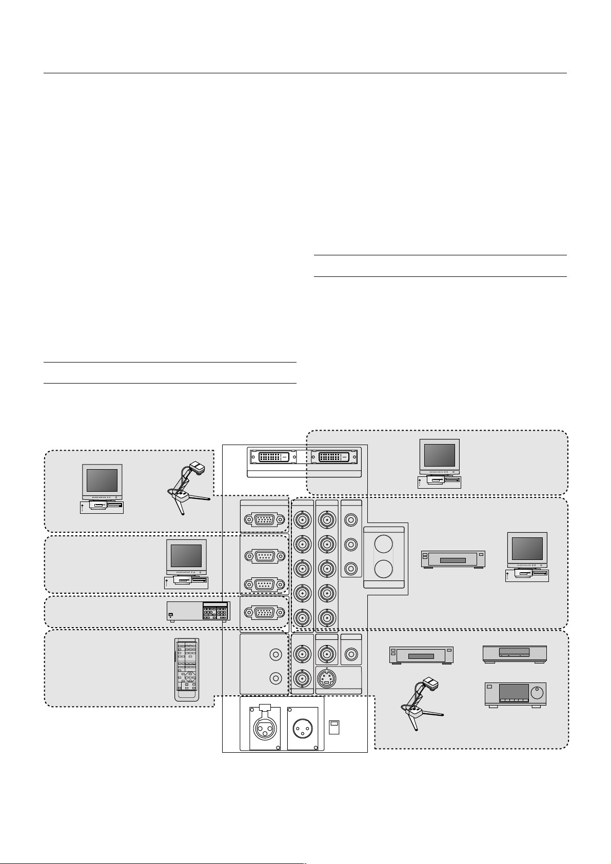
4. CONNECTIONS
When used in standalone operation
Connecting Your PC Or Macintosh Computer
Connecting your PC or Macintosh computer to THUNDER 10000sx
Projector will enable you to project your computer's screen image f or an
impressive presentation.
To connect to a PC or Macintosh :
1. Turn off the power to your projector and computer.
2. Use a signal cable (not provided) to connect your PC or Macintosh
computer to the projector.
3. Turn on the projector and the computer.
4. If the projector goes blank after a period of inactivity , it may be caused
by a screen saver installed on the computer.
Connecting Your Document Camera
You can connect the projector to a document camera. To do so, simply:
1. Turn off the power to your projector and document camera.
2. Use the supplied RGB signal cable to connect your document camera to the Video input on your projector. Or connect to the INPUT3
(RGB) on your projector.
3. Turn on the projector and the document camera.
NOTE: Refer to your document camera's owner's manual for more information
about your camera's video output requirements .
Connecting Your VCR Or Laser Disc Player
Use common RCA cables (not provided) to connect your VCR or laser
disc player to your THUNDER 10000sx Projector. To make these connections, simply:
1. Turn off the power to your projector and VCR or laser disc player.
2. Connect one end of your RCA cable to the video output connector on
the back of your VCR or laser disc player, connect the other end to
the Video input on your projector. Use standard RCA audio patch
cords to connect the audio from your VCR or laser disc pla yer to y our
sound system (if your VCR or laser disc player has this capability).
Be careful to keep your right and left channel connections correct for
stereo sound.
3. Turn on the projector and the VCR or laser disc player.
NOTE: Refer to your VCR or laser disc player owner's manual for more information about your equipment's video output requirements.
PC
Document camera
PC control
ISS-6020 Switcher
Wired remote control
OUTPUT
INPUT3
RGB
OPTION
IN
OUT
REMOTE1
REMOTE2
IN
OUT
OUT
RGB DIGITAL
INPUT2 INPUT1 INPUT4
R/Cr
G/Y G/Y
B/Cb
H/HVVVH/HV
S-VIDEO1
Y
C
INPUT7
REMOTE3
IN
INPUT9
R/Cr Cr
Y
Cb
B/Cb
INPUT5 INPUT6
VIDEO1 VIDEO2
S-VIDEO2
INPUT8
LED
ON
OFF
OUTPUT
SDI
INPUT0
DVD player VCR
Document camera
PC with RGB digital
output
DVD player
PC / Workstation
LD player
E – 17
Page 24

When Used with One Switcher (ISS-6020/ISS-6020G)
Up to 10 input signals can be accepted when the projector is connected to one Switcher. Using the projector with the Switcher allows easy
adjustment and signal selection.
RGB DIGITAL
OUTPUT
INPUT9
To REMOTE1
Optional control cable 15p-15p
(CTL-6010)
INPUT3
RGB
OPTION
IN
OUT
REMOTE1
REMOTE2
IN
OUT
OUT
INPUT2 INPUT1 INPUT4
R/Cr
G/Y G/Y
B/Cb
H/HVVVH/HV
S-VIDEO1
Y
C
INPUT7
REMOTE3
IN
R/Cr Cr
Y
Cb
B/Cb
INPUT5 INPUT6
VIDEO1 VIDEO2
S-VIDEO2
INPUT8
LED
ON
OFF
OUTPUT
SDI
INPUT0
To INPUT 1
3BNC-3BNC cable (sync on green)
4BNC-4BNC cable (composite)
5BNC-5BNC coaxial cable
(separate sync)
(recommended)
To SYSTEM CONTROL
REMOTE 1
From R, G, B, H/V on separate H
and V. on the RGB OUTPUT module
The Switcher
ISS-6020/ISS-6020G
VCR
Personal computer
• Select [Menu] → [Projector Options] → [Switcher Control] → [SW1 Level]. See page E-39 for the information in detail.
•For more information on the Switcher, refer to the user's manual accompanying the ISS-6020/ISS-6020G Switcher.
• All cables mentioned above are sold separately.
• The RGB2 terminal will not work with the Switcher Control function.
* When connecting with the VIDEO INPUT MODULE (6020-VID), set the VIDEO MODE select switch (S3001) to "8". The VIDEO MODE select
switch is located on the VIDEO INPUT MODULE (6020-VID).
NOTE: While in the Switcher Control mode, a video standard is selected at the projector.
If you set the VIDEO MODE select switch (S3001) to "8" with the QUAD DECODER installed in the Switcher ISS-6020, the image will not be displayed correctly.
In that case, first remove the QUAD DECODER from the Switcher ISS-6020.
For more details, contact your dealer.
E – 18
Page 25

When Used with Two or More Switchers (100
Inputs)
Up to 100 inputs can be accepted using the ISS-6020 Switcher.
How to make connections:
1. Connect the REMOTE 1 terminal of the master Switcher to the REMOTE 1 of the projector using the optional control cable (15p-15p/
CTL-6010).
2. Next connect the REMOTE 2 terminal of the master Switcher to the
REMOTE 1 terminal of the first slave Switcher using the same optional control cable as mentioned above. Third, connect the REMOTE
2 terminal of the first slave to the REMOTE 1 of the second slave,
and the REMOTE 2 terminal of the second slave to the REMOTE 1
terminal of the third slave (— and the REMOTE 2 of the ninth sla ve to
the REMOTE 1 of the tenth slave). Connect all the Switchers with
optional control cables.
NOTE:
• Be sure to set all the slide switches (S8603) of the Switcher to RS-422 positions. Set the one on the last slave Switcher to the appropriate position to
match the connected equipment such as a personal computer. (RS-422/RS232C for PC control of projector)
• Set the DIP switch S8601 of the Switcher.
10 inputs
10 inputs
10 inputs
Signal
Switcher
SLAVE 1
SLAVE 2
SLAVE 3
SLAVE 9
SLAVE 10
Signal
REMOTE 1
REMOTE 2
Signal
REMOTE 1
REMOTE 2
REMOTE 1
REMOTE 2
Signal
REMOTE 1
REMOTE 2
OPTION (PC)
REMOTE
CONTROL
To SLOT 1
To SLOT 2
To SLOT 10
To REMOTE 2
OPTION
(PC)
NOTE: The optional remote control RC-6320 for ISS-6020 will not work correctly in the SW Level 1 or 2 mode.
MASTER
SWITCHER
REMOTE 1
Signal (Input 1)
REMOTE
Projector
To use the projector with the Switcher ISS-6020 in the Switcher Control mode,
* When connecting with the VIDEO INPUT MODULE (6020-VID), set the VIDEO MODE select switch (S3001) to "8". The VIDEO MODE select
switch is located on the VIDEO INPUT MODULE (6020-VID).
NOTE: While in the Switcher Control mode, a video standard is selected at the projector.
If you set the VIDEO MODE select switch (S3001) to "8" with the QUAD DECODER installed in the Switcher ISS-6020, the image will not be displayed correctly.
In that case, first remove the QUAD DECODER from the Switcher ISS-6020.
For more details, contact your dealer.
E – 19
Page 26

Set the DIP switch (S8601) of the Switcher as follows:
NOTE: Slave numbers 1 to 10 must correspond to the master’s slot numbers 1 to 10.
ISS-6020
ISS-6020G
Master
Slave 1
Slave 2
Slave 3
Slave 4
Output to
The Projector
Slot 1 of the Master
Slot 2 of the Master
Slot 3 of the Master
Slot 4 of the Master
Setting of S8601
OPEN
1
2 3 4 5 6 7 8
SHORT
OPEN
2 3 4 5 6 7 8
1
SHORT
OPEN
2 3 4 5 6 7 8
1
SHORT
OPEN
2 3 4 5 6 7 8
1
SHORT
OPEN
2 3 4 5 6 7 8
1
SHORT
OPEN
Slave 5
Slave 6
Slave 7
Slave 8
Slave 9
Slave 10
Slot 5 of the Master
Slot 6 of the Master
Slot 7 of the Master
Slot 8 of the Master
Slot 9 of the Master
Slot 10 of the Master
2 3 4 5 6 7 8
1
SHORT
OPEN
2 3 4 5 6 7 8
1
SHORT
OPEN
2 3 4 5 6 7 8
1
SHORT
OPEN
2 3 4 5 6 7 8
1
SHORT
OPEN
2 3 4 5 6 7 8
1
SHORT
OPEN
2 3 4 5 6 7 8
1
SHORT
E – 20
Page 27

REMOTE 1 Connector
51423
10
This connector is used for either connecting the ISS-6020/ISS-6020G Switcher or a third
party external control device (Contact Closure). When the Switcher is used, connect it with
the optional control cable (15-15 pin; 50 ft./16m; CTL-6010) to this connector.
When used with the Switcher.
Pin No. FUNCTION
1, 2, 6 and 7 Sending and receiving data when the Switcher is used.
9 Identifying the Projector
15 Ground
3, 8,11 and 12 Used inside the Projector. Normally set to OPEN.
When using with the Switcher ISS-6020/ISS-6020G, connect No. 1,2,6,7,9 and15 pins of
the projector to the same No. pins of the switcher as shown below.
Pin Configuration of Optional CTL-6010 Cable
6978
1112131415
REMOTE 1 connector of
the Projector mini D-sub
15 pin (female)
1
7
9
15
Pins without a number are open.
Shield (frame ground)
REMOTE 1 connector
of the Switcher mini Dsub 15 pin (female)
66
1
7
22
9
15
E – 21
Page 28

When used in stand alone operation.
Pin No.
14
5
10
4,8,12,11
11pin
OPEN
OPEN
OPEN
OPEN
OPEN
OPEN
OPEN
OPEN
SHORT
SHORT
SHORT/OPEN
12pin
OPEN
OPEN
OPEN
OPEN
SHORT
SHORT
SHORT
SHORT
OPEN
OPEN
SHORT
OPEN
SHORT
OPEN
SHORT
OPEN
8pin
OPEN
OPEN
SHORT
SHORT
OPEN
OPEN
SHORT
SHORT
OPEN
SHORT
4pin
OPEN
SHORT
OPEN
SHORT
OPEN
SHORT
OPEN
SHORT
OPEN
OPEN
FUNCTION
External control mode ON
External control mode OFF
POWER ON
POWER OFF
PICTURE MUTE ON
PICTURE MUTE OFF
RGB 1 (INPUT 1)
VIDEO 1 (INPUT 5)
S-VIDEO 1 (INPUT 7)
COMPONENT (INPUT 4)
SDI (INPUT 0)
RGB 2 (INPUT 2)
VIDEO 2 (INPUT 6)
S-VIDEO 2 (INPUT 8)
RGB (DIGITAL) (INPUT 9)
RGB 3 (INPUT 3)
* When the combinations other than specified in the above table are selected, the input will be forcefully switched to RGB 1.
* The term “SHORT” means to connect with pin 15
* When in the external control mode, the POWER, INPUT, PICTURE MUTE and SOUND MUTE buttons on the remote control will not function.
NOTE: Pin 13 is the external remote signal terminal. The projector can be controlled by the same format signal as the supplied remote control from the external
controller regardless of setting on Pin 14.
NOTE: When turning off the power to the projector using the external control, do not disconnect the plug from the power outlet. These procedures are to protect your
projector and the connected equipment.
E – 22
Page 29

REMOTE2
INPUT7
S-VIDEO1
Y
C
IN
OUT
Operating Multiple Projectors with the Remote Control
You can operate multiple projectors with the same remote control in wireless operation.
To do so:
1. Select [Menu] → [Projector Options] → [Setup] → [Page 5] → [Projector ID] and assign an ID number to each projector. See also page E-39.
2. On the remote control specify the ID number of the projector to be adjusted. Press and hold the CTL and press MENU (ADDRESS) button to
enter the ID number.
You can operate the projector assigned the same ID number as the remote control.
Projector ID= 01
Projector ID= 02 Projector ID= 03
Remote Address = 03
You can daisy-chain multiple projectors and operate them separately with the same remote control in wired operation.
To do so:
1. Use the remote control cable to connect the REMOTE 2 Output of one projector to the REMOTE 2 Input of the next projector until all the projectors are
connected. Only one remote control cable is supplied with each projector.
2. Specify a unique projector ID for each projector.
3. Specify the same remote address as the projector ID to be adjusted.
NOTE: Specifying "None" for projector ID allows you to operate multiple projectors concurrently. However, some projectors may not synchronize to the other
projectors.
Projector ID= 01 Projector ID= 02 Projector ID= 03
Remote Address = 03
E – 23
Page 30

Using the RGB DIGITAL connectors
The Link mode function allows you to adjust or set multiple projectors using the RGB DIGITAL and OPTION connectors.
The DVI DIGITAL input accepts up to the SXGA (1280 x 1024 @75Hz) signal in Link mode.
NOTE: The Auto Adjust feature does not work for DVI digital signal. When DVI signal is selected and the image position is not corrected, adjust the horizontal and
vertical position using the Position screen. See page E-33 for more details.
Connection for Double Stacking in Link Mode
Connect source equipment to the master projector.
DVI-D cable (supplied)
Master
projector
Supplied ferrite clamp core
Slave
projector
OUTPUT
RGB DIGITAL
INPUT9 OUTPUT
RGB DIGITAL
INPUT9
NOTE:
* Use the supplied DVI-D cables for stacking.
OPTION
OUT
IN
OPTION
OUT
IN
* The end with the ferrite core should go to the RGB DIGITAL OUT-
PUT of the projector.
* Specify the DVI-D type when you buy DVI cable.
When you use commercially available DVI cables, they must be 5
m (16.4 feet) or less in length.
Master projector Slave projector
Bi-directional RS-232C cable (not supplied)
It is recommended that you use a commercially available distribution amplifier if you use signals other than VGA (640X480@60Hz) to SXGA
(1280X1024@75Hz) in Link mode.
Link Mode
You can daisy-chain up to 16 projectors and operate them separately with the same remote control in wired operation.
Master Slave1 Slave16
Connecting a PC with the RGB digital connector
Connect the RGB DIGITAL IN connector of the projector to a digital connector of your computer.
RGB digital connector
RGB DIGITAL IN connector
DVI-D cable
Information for Reducing Radiation of Electromagnetic Waves
To reduce unnecessary radiation of electromagnetic waves, use the supplied ferrite clamp core,
Installation Instructions
1. Open and attach the ferrite clamp core to the
supplied DVI-D cable as close as possible to
the end that goes to the projector.
* Push the catch to open the ferrite clamp core.
2. Close the ferrite clamp core tightly.
3. Fix the supplied band to the cable as a stopper.
* Pull the end of the band to tighten it. Cut off the surplus of the band.
Band
NOTE: Be sure to use the ferrite clamp core at the end of the DVI-D cable.
E – 24
Page 31

5. OPERATION
This section describes how to select a computer or video source, adjust the picture and sound, edit a signal and adjust all other settings
and adjustments for proper projector set-up.
General Controls
Before you turn on the projector ensure that the computer or video source
is turned on and that the lens cap is removed.
1. Turn On The Projector
Plug the supplied power cable into the AC outlet. The main power
switch is on the front panel of the projector . By pushing up this s witch,
the projector will go into its standby mode and the POWER indicator
will glow orange. Only after you press the 'POWER ON' button on
the remote control or projector cabinet will the POWER indicator
turn to green and the projector will fully turn on.
2. Select The Computer Or Video Source
Press the INPUT button on the remote control to select the desired
source. Or press the MENU button on the remote control and use
the Source Select to select your video source: Video , S-Video, RGB ,
Y/Cr/Cb, RGB Digital or SDI.
3. Adjust The Image
Press the ADJUST PICTURE button or the ADJUST WHITE BAL
on the remote control or select the [Menu] → [Adjust (Source)] to
adjust the picture.
4. Turn Off The Projector
First press the POWER OFF button on the remote control or the
projector cabinet. Allow the fan to cool the projector for three minutes. This will extend the life of the lamp. After the cooling fan stops
working, the POWER indicator will change to a steady orange glow
and the projector will be in the stand-by mode. Then push down the
main power switch on the front panel. The PO WER indicator will go
out. If y ou desire to move the projector then unplug the po wer cable .
Using The Menus
1. Press the MENU button on the remote control to display the menu.
2. Use the ▲ or ▼ button on the remote control to select the sub menu.
3. The right-oriented delta symbol indicates further choices are available. Press the 䊳 button to highlight the item y ou want to adjust or set
in the selected menu.
4. Press the ▲ or ▼ button on the remote control to select the item.
5. Press the ENTER button on the remote control to display the adjustment screen or dialog box.
6. Adjust the level or turn the selected item on or off by using 䊴 or 䊳 on
the remote control. The on-screen slide bar will show y ou the amount
of increase or decrease.
NOTE: The change is stored automatically when any one of the following procedures is performed:
* The on-screen disappears.
* The projector goes into standby.
* One input is switched to another.
7. Repeat steps 2-5 to adjust an additional item, or press the CANCEL
button on your remote control to quit.
Shutter mechanism
The projector is equipped with "Shutter" feature, which allows the user
to shut off the light completely on the screen. To use the shutter function, hold down the CTL button, and press the MUTE PICTURE button
on the remote control.
IMPORTANT:
• The projector will turn off and go into the standby mode after 850
hours of service.
• The projector should be unplugged if it will not be used for an extended period.
• If you want to turn off the image briefly (five minutes or less), press
the MUTE PICTURE button instead of turning the projector off and
on.
• The projector will display a black, b lue image or logo if no input signal
is present.
• Do not turn the projector off and then immediately back on. The Projector needs to cool down for three minutes before it is powered on
again.
CAUTION: Do not turn off the main power while the cooling fan is working.
E – 25
Page 32

Customizing Basic/Custom Menu
The Basic/Custom menu can be customized to meet your requirements.
Selecting a menu item from the "Basic/Custom Menu Edit" list, allows
you to custom tailor the menu items to your needs.
1. Select "Basic/Custom Menu Edit" to displa y the "Basic/Custom Menu
Edit" screen.
2. Use the ▲ or ▼ button to highlight your selection and press the Enter
button to place a check mark next to an option. This action enables
that feature.
Press the Enter button again to clear the check box.
NOTE: If the "Advanced Menu" item has been selected on the Menu mode,
you get the "Confirmation Change Menu" upon completion of "Basic/Custom
Menu" editing. In this case, selecting "Yes" then "Enter" will close all the menus
and apply the changes from the Advanced menu to the Basic/Custom Menu.
If you select "No" then "Enter" functions, then all menu items will return to
the Advanced menu, but your changes will still be available within the "Basic/
Custom Menu" selection. To display the previously tailored Basic/Custom
Menu, select "Basic/Custom Menu" from the "Menu Mode".
An item "To Advanced Menu" will be added to the bottom of the Basic/ Custom Menu.
Selecting this item and pressing the "Enter" button will display the
"Advanced Menu" features.
If you select an item with a solid triangle 䊳 and press the Enter b utton
on the remote control or the projector cabinet, you can enable all the
items within that submenu.
Also you can turn on an item within the submenu without placing a
check mark on the main menu item.
NOTE: Up to 12 main menu items (within Basic/Custom Menu Edit, not including submenu items) can be selected.
3. In order for the changes to take effect, use the 䊴 or 䊳 button on the
remote control or the projector cabinet to highlight "OK", then press
the Enter button. To cancel the changes, use the ▲ or ▼ buttons to
highlight "Cancel" and press the "Enter" button.
To return to the factory def ault, select "Reset" then press the "Enter"
button.
The default Basic/Custom Menu items are:
Source Select (RGB1/2/3, Component (Y/Cb/Cr), Video1/2, S-Video
1/2, DVI digital, and SDI), Brightness, Contrast, Pix el Adjust and Position.
NOTE: Once you have selected OK on the Basic/Custom Menu Edit screen,
you cannot cancel the changes on the Menu screen. However, you can reedit the menu items over again as described in the steps above.
E – 26
Page 33

A List of Direct Key Combinations
CTL+ INPUT (1-10) Switches to any selected signal found in the Entry List.
To enable this combination, you must first assign specific remote keys for direct input
selection in the Entry Edit window.
CTL+ ENTER (While displaying Entry list) Displays the Entry Edit Command window.
CTL+ MUTE PICT/SHUT Blocks all Projector Light Output.
CTL+CANCEL Returns to the previous menu without closing the slidebar or dialog.
CTL+ UNDO Clears all menus or adjustment/setting screens. All adjustments are saved automatically.
䊴
CTL+
/ 䊳 / ▲ / ▼ Moves the slidebar or dialog box horizontally or vertically.
While using zoom on remote control: Displays the magnifying glass icon.
䊴
CTL+
Deletes one letter or numeral in the entry screen.
CTL+MUTE OSD Turns off the on-screen display. Press again to turn on the on-screen display.
INPUT(1-10) in SW Level mode Displays the Select switcher Input Slot window.
NOTE: This feature is available for SW 2 Level mode only.
When the SW 1 Level mode is selected, pressing INPUT key switches to the corresponding
slot without displaying the Select Slot window.
CTL+ MENU/ADDRESS Displays the remote ID entry window.
CTL+ IMAGE/PROJECTOR Sequentially selects the Projector Options sub menu.
CTL+ POSI/LENS Displays the Lens Shift control window.
CTL+ KEYST/R Turns on red. Available only when the projector is in the test pattern mode.
CTL+ AMP/G Turns on green. Available only when the projector is in the test pattern mode.
CTL+ E-LIST/B Turns on blue. Available only when the projector is in the test pattern mode.
CTL+ MAGNIFY/ZOOM Zooms the lens in and out
CTL+ FOCUS Adjusts the lens focus.
E – 27
Page 34

Menu Tree
Advanced Menu
Source Select
Adjust (Source)
Ref Adj
Factory Default
Projector Options
Help
Test Pattern
When Switcher Control is
turned on:
Switcher
Entry List
Stand alone
RGB1
RGB2
RGB3
Component (YCbCr)
Video1
Video2
S-Video1
S-Video2
RGB (DIGITAL)
SDI
Entry List
Brightness
Contrast
Saturation
Color
Hue
Sharpness
V-Aperture
Gamma Correction
Color Temperature
Brightness
Contrast
Signal Level
0 – 100
NTSC, Graphics, Graphics NTSC, PAL/SECAM2.8,
PAL/SECAM, Natural 1/Natural 2
Brightness R/G/B
Contrast R/G/B
R/G/B, Y/Cb/Cr, Y/Pb/Pr
Picture
White Balance
Image
Video Adj
Option Adj
Lens Memory
Signal Type
Switcher
Pixel Adjust
Position
Aspect Ratio
Resolution
Overscan
Video Filter
Blanking
Noise Reduction
Color Matrix
Y/C Deray
Telecine
Motion Select
Motion Level
YTR Adjustment
CTR Adjustment
Clamp Timing
Sync Protection
VD Delay
Reference / Custom
Clock / Phase
Horizontal / Vertical
Input Signal 1.25:1 / 1.33:1 / 1.78:1 / 1.85:1 / 2.35:1
Display Area 1.25:1 / 1.33:1 / 1.78:1 / 1.85:1 / 2.35:1
Auto / Native
0% / 5% / 10% / 25%
On / Off Top / Bottom / Left / Right
Luminance Off / Low / Medium / High
Chrominance Off / Low / Medium / High
Select Color Matrix HDTV / SDTV
Delect Color Matrix Type B-Y/R-Y, U/V, Cb/Cr
Pb/Pr, IVX
Auto / Off
Still / Adaptive
Auto / Tri-Sync / Front Porch / Adjust
RGB / Component
Gain
Volume
E – 28
Red / Green / Blue
Page 35

Advanced Menu
Source Select
Adjust (Source)
Ref Adj
Factory Default
Projector Options
Help
Test Pattern
Keystone
Lamp
Ref. White Bal.
All Data / Current Signal
Including Entry List
Timer
Menu
Setup
Link Mode
Switcher Control
Lamp Mode
Brightness R/G/B, Contrast R/G/B
On / Off Timer
Sleep Timer
Page 1
Page 2
Menu Mode (Basic/Custom Menu, Advanced Menu, Service Menu)
Basic/Custom Menu Edit
Language (English / German / French / Italian / Spanish / Swedish / Japanese)
Menu Display Time (Manual / Auto 5 sec / Auto 10 sec / Auto 30 sec)
Display Select (Date, Time, Input Terminal, Source Name, Projector ID, On/Off)
Date Format
Date, Time Preset
Maximum / Medium / Minimum
Execute Switch (Active / Inactive)
Edit
Preset Time (Off / 0:30 / 1:00 / 1:30 / 2:00)
(MM/DD/YYYY, MM/DD/YYYY ddd, DD/MM/YYYY, DD/MM/YYYY ddd
YYYY/MM/DD, YYYY/MM/DD ddd, Month DD, YYYY, Month DD, YYYY ddd)
Page 1
Page 2
Page 3
Page 4
Page 5
Orientation (Desktop Front / Ceiling Rear / Desktop Rear / Ceiling Front)
Background (Blue / Black / Logo)
S-Video Mode Select (Off / S2)
Control Panel Key Lock (Enable/Disable)
Signal Select
RGB 1 (Auto / RGB / Component)
RGB 2 (Auto / RGB / Component)
Sync Termination
RGB 1 (Hi-Z / 75Ω)
RGB 2 (Hi-Z / 75Ω)
Signal Select
Video 1 (Auto / NTSC3.58 / NTSC4.43 / PAL PAL60 / SECAM)
Video 2 (Auto / NTSC3.58 / NTSC4.43 / PAL PAL60 / SECAM)
S-Video 1 (Auto / NTSC3.58 / NTSC4.43 / PAL PAL60 / SECAM)
S-Video 2 (Auto / NTSC3.58 / NTSC4.43 / PAL PAL60 / SECAM)
Switcher (Auto / NTSC3.58 / NTSC4.43 / PAL PAL60 / SECAM)
Auto Adjust (RGB Only)
Power Management
Power Off Confirmation
Keystone Save
Doubler
Last Memory
Seamless
Lens Memory
User Name
Communication Speed (4800 / 9600 / 19200 / 38400)
Projector ID (Enable / Disable) 1 – 64
Default Source Select (Last / Select)
Standalone
[RGB1 / RGB2 / RGB3 / Component (YCbCr) / Video1 / Video2 / S-Video1 /
S-Video2 / RGB (DIGITAL) / SDI]
SW 1 Level (Slot 1 – 10)
SW 2 Level (M-01 S-01 – M-10 S-10)
Cross Hatch, Gray Bars
Black Raster, Gray Raster
White Raster
Red / Green / Blue
Contents
Source Information
Projector Information
Standalone / Master / Slave
Standalone / SW 1 Level / SW 2 Level
Contents
Page 1
Page 2
Page 3
Page 1
Page 2
Page 3
Page 4
Source Name / Input Terminal / Entry No. / Horizontal Frequency /
Vertical Frequency / Sync Polarity
Signal Type / Video Type / Sync Type / Interlace / Resolution / Direct Key
Aspect Ratio (I) / Aspect Ratio (D) / Gamma Correction / Noise Reduction (L) /
Noise Reduction (C) / Color Matrix / Matrix Type
User Name / Serial Number / Lamp Hour Meter / Projector Usage / Projector ID
Version (BIOS / Firmware / Data / SUB-CPU)
Formatter Version (CPU / PROM / Prism)
FPGA Version (OSD / JOE)
Link Mode (Master / Slave)
E – 29
Page 36

Menu Elements
Title bar
Highlight
Ta b
Help Button
Radio button
OK Button
Cancel Button
Solid triangle
Check box
Slide bar
Menu windows or dialog boxes typically have the following elements:
Title bar: Indicates the menu title.
Highlight: Indicates the selected menu or item.
Solid triangle: Indicates further choices are available. A highlighted triangle indicates the item is active.
Tab: Indicates a group of features in a dialog box. Selecting on any tab brings its page to the front.
Radio button: Use this round button to select an option in a dialog box.
Check box: Place a checkmark in the square box to turn the option On.
Slide bar: Indicates settings or the direction of adjustment.
OK button: Press to confirm your setting. You will return to the previous menu.
Cancel button: Press to cancel your setting. You will return to the previous menu.
Help button: Press the Help button on the remote control to display help.
E – 30
Page 37

Menu Descriptions & Functions
Source Select
Enables you to select a video source such as a VCR, DVD player , laser
disc player, computer or document camera depending on what is
connected to your inputs.
Press the up/down buttons on your remote control or the projector cabinet to highlight the menu for the item you want to adjust.
* RGB1,2,3
* Component (YCbCr)
* Video 1, 2
* S-Video 1, 2
* RGB (Digital)
* SDI
Swicher
You can select the slot number from 1 to 10 of the Switcher(s) ISS-
6020.
Entry List
Displays the list of the entry signals. Use the ▲▼ buttons on your remote control or the projector cabinet to select the signal and press the
ENTER button on the remote control or the projector cabinet to project
the image of the selected source.
Entry Edit Command
You can edit the signal on the entry list.
To do so:
1. While pressing and holding CTL, press ENTER on the remote control to
display the Entry Edit Command window.
* Cut Enables you to remove a selected signal from the list and place
it on the "clipboard" in the projector.
* Copy Enables you to copy a selected signal from the list and place it
on the "clipboard" in the projector.
* Paste Enables you to paste the signal placed on the "clipboard" to
any other line of the list. To do this, select "Paste" and then select the
line number you want to paste to. Last press ENTER.
* Edit Enables you to change source name or assign the direct key.
* The following buttons are not available for the currently projecting
signals:
1) The Cut and Paste buttons on the Entry Edit Command screen
2) The Input Terminal button on the Entry Edit screen
When using with a single Switcher ISS-6020:
Use the SELECT ▲ or ▼ button to select the desired slot number from
1 to 10 of the ISS-6020 Swicher and press ENTER.
When using with two or more Switcher ISS-6020:
Use the SELECT ▲ or ▼ button to select the master slot number from
1 to 10 and then the slave slot number from 1 to 10 on the Select Slot
menu. Select OK and press ENTER.
To close the window without storing the settings, select Cancel and
press ENTER.
When complete, select OK and press ENTER. To exit without storing setting, select Cancel.
Select "Source Name" and press ENTER to display the Source Name
Edit window. You can change source name on this window.
Select "Input Terminal" and press ENTER to display the Input T erminal window. You can change input terminal on this window.
RGB1, RGB2, RGB3, and RGB(DIGITAL) can be selected for RGB
signals; RGB1, RGB2, Component, and RGB(DIGITAL) can be selected for component signals; Video 1/2, S-Video 1/2 , and
RGB(DIGITAL) can be selected for Video and S-Video signals.
Select "Direct Key" and press ENTER to displa y the Direct K e y window.
You can assign specific remote keys f or direct signal input selection.
NOTE: Existing direct key settings are overwritten with new settings.
E – 31
Page 38

Select "List" and press ENTER to display the direct Ke y assignment
list.
Select "OK" and press ENTER to close the window.
To close the List window, press CANCEL on the remote.
White Balance
Color Temperature
This feature adjusts the color temperature using the slide bar.
Move the slide bar to the right to increase the color temperature for
a bluish image; to the left to decrease it for a reddish image.
Brightness
Brightness for each color (RGB) is used to adjust the black level of
the screen.
Adjust (Source)
Picture
Brightness
Adjusts the brightness level or the back raster intensity.
Contrast
Adjusts the intensity of the image according
to the incoming signal.
Saturation
Adjust saturation at the white peak.
Color
Increases or decreases the color saturation level (not a vailable for RGB).
Hue
Varies the color level from +/- green to +/-blue. The red le v el is used as
reference. This adjustment is only valid for Video and Component inputs (not available for RGB).
Contrast
Contrast for each color (RGB) to adjust the white lev el of the screen.
Signal Level
R/G/B, Y/Cb/Cr or Y/Pb/Pr Gain:
Adjust RGB, Component or HDTV Gain to match multiple projector
color uniformity.
Image
Pixel Adjust (when Auto Adjust is off)
Sharpness
Controls the detail of the image for Video (not available for RGB and
Component).
V-Aperture
Adjusts edge enhancement in the vertical direction. (not available for
RGB)
Gamma Correction
This option corrects gamma. Select the appropriate item.
NTSC .......................... Setting for NTSC signals
Graphics ..................... Setting for Computer Graphics
Graphics/NTSC ........... Setting for both Computer Graphics and NTSC sig-
nals (Default value)
PAL/SECAM 2.8 ..........Setting for PAL and SECAM signals at the gamma
value of 2.8
PAL/SECAM ................Setting for PAL and SECAM signals
Natural 1 ..................... Setting for Video and S-Video signal
Natural 2 ..................... Setting for component signal (γ value 2.2)
E – 32
Displays the Clock and Phase adjustments.
Clock ............ Use this item with the "Auto Adjust off" to fine tune the com-
Phase ........... Use this item to adjust the clock phase or to reduce video
Use "Phase" only after the "Clock" is complete.
puter image or to remove any vertical banding that might appear.
noise, dot interference or cross talk. (This is evident when
part of your image appears to be shimmering.) Use the 䊴 and
䊳
buttons to adjust the image.
NOTE: When Auto Adjust is turned ON on the Page 4 of Setup, the Clock
adjust is not available on this Pixel Adjust screen.
Page 39

Horizontal/Vertical Position (when Auto Adjust is off)
Video Filter
This feature reduces video noise. Select the appropriate filter for
your signal.
Adjusts the image location from left to right.
This adjustment is made automatically when the Auto Adjust is turned
on.
Aspect Ratio (not available for RGB)
You can select the aspect ratio for input signal and display area respectively.
Select the appropriate aspect ratio using the SELECT 䊴 , 䊳 , ▲, or
▼ button.
NOTE: When "Resolution" is set to "Native", this feature is not available, and
the stored settings and adjustments are invalid.
Resolution (when Auto Adjust is off)
This allows you to activate or deactivate the Advanced AccuBlend
feature.
Auto ............. Turns on the Advanced AccuBlend feature. The projector au-
tomatically reduces or enlarges the current image to fit the
full screen.
Native ........... Turns off the Advanced AccuBlend feature. The projector dis-
plays the current image in its true resolution. See "Auto Adjust (RGB Only)" on page E-38 for turning on or off the Auto
Adjust feature.
Bar 0 ............ Off
Bar 1/3 ......... High
Bar 2/3 ......... Medium
Bar full ......... Low
Blanking
This feature allows you to mask any unwanted area of the screen
image.
Blanking On/Off:
This setting enables or disables the blanking function.
On ................ Blanking function is enabled.
Off ................ Blanking function is disabled.
* Adjustment of vertical display range
Adjust the Top, Bottom, Left or Right blanking with the SELECT 䊴 or
䊳
button.
Video Adj
NOTE: While you are displaying an image with higher resolution than the
projector's native resolution (SXGA:1280 x 1024), even when you are in the
Native mode, the image is displayed full screen using the Advanced AccuBlend
feature.
NOTE: The image with lower resolution than SXGA(1280 x 1024) is displayed in small when you are in the Native. In this case, you can use the lens
shift, zoom and focus adjustments, which you saved in advance with "Custom" of "Lens Memory", to enlarge the image to fit on the screen.
Overscan
You can select overscan percentage for RGB signal.
Select the appropriate option using the SELECT 䊴 or 䊳 button.
NOTE: When "Resolution" is set to "Native", this feature is not available, and
the stored settings and adjustments are invalid.
Noise Reduction
Select one of the following three levels for reducing video noise.
Low, Medium or High.
NOTE: The lower the Noise Reduction level, the better the image quality.
Increasing Noise Reduction lowers video bandwidth.
E – 33
Page 40

Color Matrix
First, select an appropriate color matrix for your input signal, either
HDTV or SDTV. Then select an appropriate matrix type from B-Y/RY, Cb/Cr, Pb/Pr or IVX.
NOTE: The Color Matrix feature is available for component video signal only.
Option Adj
Clamp Timing
Y/C Delay (not available for RGB)
Adjusts Y/C delay level.
Telecine
Use 3:2 pull down correction to eliminate jitter and artifacts in video.
Auto ............. For film source such as a DVD player
Off ................ For signals other than film sources
Motion Select
Sets the interpolation method. Selects Still or Adaptive. Still is used
for non moving images such as a document camera. Select Adapter
for all motion video.
Motion Level
Adjusts level of motion detection when Adaptiv e is selected.
According to the signal, this function sets the detection position (i.e.,
clamp position) of the black level reproduction of the analog input
signal. Normally this is not used. (1080P is set as the default)
Auto ............. This is the normal setting.
Tri-Sync ....... This is set when projecting HDTV video.
Front Porch .. This is set when the picture quality does not improve even
though Auto or Tri-Sync has been set.
Adjust .......... This permits the video clamp position for each signal to be
set. Use "Adjust" when a clamp timing error occurs at the time
of special analog signal reception such as 1080P. Note that
"Adjust" is not valid for doubler signals such as NTSC and
PAL.
To delete the "Clamp Timing" setting screen, select the SELECT ▼
button and press the ENTER button, or press the remote control
CANCEL button.
Sync Protection
When a VCR, DVD, or some other equipment that supports
Copyguard (a copy prevention system) is played back, the screen
may be displayed in a curved manner. Adjustments are made in
such circumstances. Use the SELECT 䊴 or 䊳 button to adjust the
VD level.
VD Delay
YTR Adjustmen (not available for RGB)
Adjusts luminance transient time.
CTR Adjustment (not available for RGB)
Adjusts chroma transient time.
This feature is used to correct vertical jitter of non-standard interlaced signal.
NOTE: When connecting with a scan converter:
If an image from the scan converter is not correctly displayed, adjust to
select the best level point so that the image is displayed correctly.
E – 34
Page 41

Lens Memory
This function serves to store the adjusted value when using the Shift,
Focus, and Zoom buttons of the main unit or the remote control.
Usage Example
When you wish to display on a screen having a 4:3 aspect ratio an
NTSC or other 4:3 aspect ratio signal and an SXGA or other 5:4 aspect
ratio signal:
Switcher (available only when used with ISS-6020)
Gain
Perform shift, focus, and zoom adjustments to set the vertical screen
size of the vertically long 5:4 aspect ratio signal to standard.
Both 4:3 apsect ratio signals and 5:4 aspect ratio signals can now be
displayed.
Note that with these shift, focus, and zoom adjustments, the 4:3 aspect
ratio signal will become smaller on the screen.
To eliminate this size reduction, adjust the shift, focus and zoom to the
optimum condition for each of the 4:3 aspect ratio signal and the 5:4
aspect ratio signal. Memory (storage) of each of these values will permit projection at an optimum condition upon signal switching.
1) Select "Projector Options" → "Setup" → "Page 4" → "Lens Memory" and
then insert a check mark into the Lens Memory check box.
2) Set to no-signal condition or project a 5:4 aspect ratio signal and then
adjust each of shift, focus, and zoom.
3) Select "Reference" under "Adjust(Source)" → "Lens Memory" → "Refer-
ence/Custom" and store your adjustments.
* For signals other than those having a 5:4 aspect ratio (or, 5:4 aspect ratio
signals that you wish to adjust separately), adjust shift, focus, and zoom,
select "Custom" under "Reference/Custom", then press "Store".
The differences between "Reference" and "Custom" are described below.
"Reference": Valid adjustment value for a no-signal condition and a
newly input signal "Custom": Custom adjustment v alue for a specific
signal
Note that when "Reference" is stored, it will be overwritten since it is
not an adjustment that changes with each signal.
In the aforementioned description, signals having a 5:4 aspect ratio
are restricted to "Reference", but signals having other aspect ratios
can also be used as standard signals.
Another method to store values is to press the INFO button while
holding down the CTL button of the remote control.
Note that when using the remote control for storing, storage will be
in "Reference" when the "Lens Memory" setting of the menu is "Reference", and storage will be in "Custom" when the setting is "Custom". Defaults such as newly input signals are "Reference".
* See “Tips on Adjusting Focus for Lens Memory Function” on page E-47 for
more information.
Signal Type
Select either the RGB signal type or the Component signal type.
RGB ............. RGB signal
Component .. Composite signals such as Y/Cb/Cr, Y/Pb/Pr
NOTE: This feature is available on RGB 1 and 2 only.
This feature adjusts the input level of the signal. This must be done
to each color:R, G, and B.
Volume
This feature adjusts the volume of the audio output. Adjust the sound
corresponding to the slot.
Ref Adj
Keystone
This feature corrects the keystone (trapezoidal) distortion to make the
top of the screen longer or shorter to be the same as the bottom.
Use the 䊴 or 䊳 buttons on the slide bar to correct the keystone (trapezoidal) distortion.
Keystone distortion
NOTE:
1) With the projector aimed directly at the screen the maximum keystone angle
that can be corrected is +/- 7.5 degrees.
2) When "Resolution" is set to "Native", this feature is not available, and the stored
settings and adjustments are invalid.
Depending on the type of graphics being used, the picture may get blurred or
keystone correction may not be possible when excessive keystone correction
is used.
The idea is, the closer you are to native resolution, the better image you will
see.
NOTE: The keystone feature is not available when the test pattern or the blue
back is displayed.
Normal
E – 35
Page 42

Lamp
Lamp Mode
Projector Options
Enables you to set preferences and other operating options.
This feature allows the lamp power supply to operate under three settings.
Maximum ..... This setting consumes maximum current from the AC input
and results in the most light output.
NOTE: The Maximum mode shortens the lamp life. Be sure to use this mode
at temperature of 95˚ F (35˚C) or less.
Medium ....... This setting allows the lamp power supply to draw a medium
amount of current from the AC input source and allows for
medium power consumption.
Minimum ..... This setting consumes minimum current from the AC input
and results in the least light output.
Reference White Balance
This feature adjusts the white balance that is used as a reference.
This adjustment affects all sources. The Ref.White Bal. is available
for test pattern only.
Factory Default
Returns all adjustments and settings to the factory preset level.
All Data ....................... Reset all the settings for all the signals to the factory
preset.
NOTE: The items that can be reset are all the settings and adjusts except for
Language, Projector ID, Lamp Hour Meter, Projector Usage and Communication Speed.
Including Entry List
Also deletes all the signals in the Entry List and returns to the factory preset.
Timer
Enables you to turn on or off your projector automatically at a specified
time. Two timer functions are available: On/Off Timer and Sleep Timer.
On/Off Timer
Up to eight settings can be programmed.
• Before setting On/Off Timer, make sure that Date, Time Preset feature is
set.
• Even after setting On/Off Timer, turning the projector on or off with the
remote control is possible.
• There are two time display formats: 24-hour or AM/PM format.
1. Open the On/Off Timer window.
2. Select EDIT and press ENTER on the remote control to open the EDIT
window.
Current Signal .............Resets the adjustments for the current signal to the
factory preset levels.
NOTE: All the items in "Adjust (Source)" can be reset.
3. Set the Week, Day, On-Time and Off-Time using the Select buttons and
Source buttons (1 thru 10). To cancel the on-time or off time, use Delete.
4. Select Set and press the ENTER button on the remote control to complete
the setting. To close, select Close.
E – 36
Page 43

5. To enable your setting, select Active on the Execute Switch.
6. Select OK and press the ENTER button on the remote control to complete
the setting.
NOTE: When On Timer is set and the projector is in the standby mode, the
Status indicator flashes green to show that On Timer program is active. The
projector must be in stand-by mode at the time of turning on. The preset
power-on time will be void if the cooling fan is working or an error occurs.
Unplugging the projector cancels your 1 Week programs regardless of
whether the program was executed or not. However, your Every Week program will not be cancelled even if you unplug the projector.
Sleep Timer
1. Select your desired time between 30 minutes and 2 hours in 30 minute
increments.
2. Select Set and press the ENTER button on the remote control.
3. The remaining time starts counting down.
Menu Display Time
This option allows you to select how long the projector waits after the
last touch of a button to turn off the menu.
The preset choices are "Manual", "Auto 5 sec", "Auto 10 sec", and "A uto
30 sec". The "Manual" is the factory preset.
Manual ......... The menu can be turned off manually.
Auto 5 sec .... The menu will automatically be turned off in 5 seconds if no
buttons are pressed within 5 seconds.
Auto 10 sec .. The menu will automatically be turned off in 10 seconds if no
buttons are pressed within 10 seconds.
Auto 30 sec .. The menu will automatically be turned off in 30 seconds if no
buttons are pressed within 30 seconds.
[Page 2]
4. The projector will turn off after the countdown is complete.
Menu
[Page 1]
Allows you to set preferences for the on-screen menu.
Press "OK" to save your changes for all the features.
Menu Mode
This feature allows you to select two menu modes: Advanced Menu
and Basic/Custom Menu.
Advanced Menu .......... This is the menu that contains all the available menus
and commands.
Basic/Custom Menu....This is the menu that you can customize using the
Basic/Custom Menu Edit to fit your needs.
The factory default Basic/Custom menu includes:
Source Select (RGB1/2/3, Component(Y/Cb/Cr), Video1/2, S-Video1/
2, RGB (Digital), and SDI), Brightness, Contrast, Pixel Adjust and
Position. See page E-26 f or instructions about how to customize the
Basic/Custom Menu.
Language
You can choose one of seven languages for on-screen instructions.
The options are: English, German, French, Italian, Spanish, Swedish
and Japanese.
Display Select
You can choose the desired status information to be displayed on the
screen. The desired status information will be displayed each time you
switch between sources.
Date Format
Eight display formats can be selected. This date f ormat sets the current
date that appears on the upper left corner of the screen.
Date, Time Preset
Setting the Current Date and Time
You can set the current time, month, date, and year.
1. Type in date.
Enter month, date and year in this order using INPUT buttons on the remote control.
Month and date must be entered in two digits. For example, to display
"February", press "0" and "2".
2. Type in time.
Time is expressed in the 24-hour format. For example, 6:00 p.m. is entered as 18:00.
3. Select "OK" and press ENTER.
Closing the window allows the clock to start.
The current year, month, date and time are displayed on the top of the
screen.
NOTE: The projector has a built-in clock. The clock will keep working for
about 3 days after the main power is turned off. If the main power is off for
3 days or more, the built-in clock will be reset. If the built-in clock is reset,
set the date and time again. The built-in clock will not reset while in the
standby condition.
E – 37
Page 44

Setup
Enables you to set operating options.
Press "OK" to save your changes for all the features of Page1, Page2,
Page3, Page 4 and Page5.
[Page 1]
Orientation
This reorients your image for your type of projection.
The options are: desktop front projection, ceiling rear projection, desktop rear projection, and ceiling front projection.
Background
Use this feature to display a blue/ black screen or logo when no
signal is available. The default background is blue.
S-Video Mode Select
This feature is used to select the S-Video signal detection mode.
This allows identifying of the S-Video signals with different aspect
ratio (Zoom signal 16:9, Wide Zoom signal 4:3).
Sync Termination (RGB1/2)
This functions is used to select the impedance of the sync signal.
Select " 75 Ω " or "Hi-Z".
NOTE: The default setting is "75Ω ". This should be "75Ω" for normal use.
Select the "Hi-Z" when inputting a TTL signal.
[Page 3]
Signal Select (VIDEO 1/2, S-VIDEO1/2 and Switcher)
This feature enables you to select composite video standards manually. Normally select "Auto".
Select the video standard from the pull-down menu. This must be
done for Video and S-Video separately.
"Switcher" is setting f or Video and S-Video in SW 1 Le vel or 2 mode.
[Page 4]
S2 ................ Identifies Zoom or Wide Zoom signal.
OFF .............. Does not identify any S-video signal.
Control Panel Key Lock
This option turns on or off the Control Panel Key Lock function.
To lock the control panel key functions, select the Enable button. To
unlock the control key functions, select the Disable button.
NOTE:
* This Control Panel Key Lock does not affect the remote control and the PC
Control functions.
* When the Control Panel Key Lock function is enabled, pressing and hold-
ing the CANCEL button for about 10 seconds will disable the setting.
[Page 2]
Signal Select (RGB1/2)
Allows you to choose "RGB" for an RGB source such as a computer, or "Component" for a component video source such as a
DVD player. Normally select "Auto" and the projector automatically
detects a component signal. However there may be some component signals that the projector is unable to detect. If this is the case ,
select "Component".
Auto Adjust (RGB Only)
When "Auto Adjust" is turned on, the projector automatically determines the best resolution for the current RGB input signal to project
an image using Advanced AccuBlend Intelligent Pixel Blending T echnology .
The image can be automatically adjusted for position and stability;
"Horizontal Position", "Vertical Position" and "Clock".
On ................ Automatically adjusts image display functions ( "Horizontal
Position", "Vertical Position" and "Clock".)
Off ................ User can adjust the image display functions ( "Horizontal Po-
sition", "Vertical Position" and "Clock") manually.
NOTE: The projector has a feature that enters a signal automatically in the
Entry List once you made any adjustments. However, this feature is not available if you adjust a signal using the Auto Adjust feature. To register the
signal after you use the Auto Adjust feature, first you need to make any one
adjustment manually.
E – 38
Page 45

Power Management
When this option is on and there is no RGB input for five minutes or
more, the projector will automatically turn itself off.
Power Off Confirmation
This option determines whether a confirmation dialog for turning off
the projector will appear or not.
Keystone Save
This option enables you to save your current keystone settings.
Saving your change once affects all sources . The changes are sav ed
when you turn off the projector.
Doubler (Video / S-Video Only)
This sets double speed interpolation of the video signal.
[Page 5]
On ................ Non-interlaced display
Off ................ Interlaced display
NOTE: The setting will take effect from the next video signal display.
Last Memory
The projector stores the last signal data in memory for each input
(RGB1, RGB2, RGB3, Component [YCbCr], Video 1, Video2, SVideo1, S-Video2, RGB [DIGITAL] and SDI).
This feature will reduce switching time between sources.
If a commercially available switcher is connected, turning on this
feature may cause the image to appear incorrectly.
Should this happen, turn this feature off to mute the screen during
switching.
Normally if this feature is turned on when the projector is used in
standalone mode, switching time between sources will be short-ened.
Seamless
This option selects modes of switching when changing input selections.
During the time of switching from one input to another, y ou can freeze
or mute an image.
On ................ Enables the Seamless feature to freeze the image for a short
period of time during input switching.
Off ................ Disables the Seamless feature to mute the image for a short
period of time during input switching. This will result in no
image (black screen) at the time of input switching.
Lens Memory
This function applies the stored lens shift, focus, and zoom adjustment values to the selected signal.
The function performs a setting that enables or disables the "Adjust
(Source)" - "Lens Memory" functions of the menu.
On ................ Enables the lens memory function and apply the stored shift,
focus, and zoom setting values to the selected signal.
Off ................ Disables the lens memory function so that there will be no
application of stored shift, focus, and zoom setting values.
NOTE: The shift, focus, and zoom adjustment values can be stored regardless of whether or not the lens memory function is enabled.
NOTE: In the Link mode the Lens Memory feature is not available.
User Name
Type in your desired name using the INPUT buttons on the remote
control.
Select one character at a time with the INPUT buttons 1 through
Communication Speed
This feature sets the baud rate of the PC CONTROL connector (Mini
D-Sub 9 Pin).
It supports data rates from 4800 to 38400 bps.
The default is 38400 bps. Select the appropriate baud rate for your
equipment to be connected.
Projector ID
Each projector needs its own unique addresses when used in serial
communication mode. You can choose one of 64 unique address
using the spin box. First select Enable . Keep pressing increases the
number.
To make your setting available, select OK.
Default Source Select
You can set the projector to default to an y one of its inputs each time
the projector is turned on.
Last .............. Sets the projector to default to the previous or last active in-
put each time the projector is turned on.
Select ........... Displays the selected source input every time the projector is
started up. Select an input from the pull-down menu.
Link Mode
This feature is used for multiple projector connection using RGB
Digital Input/Output connectors. The master projector is set to Master.
The other slave projectors are set to Slav e. When not using Link mode,
set to Standalone. See page E-14 for setting up for double stacking in
link mode.
Switcher Control
This feature sets the projector in communication with the ISS-6020
Switchers.
Stand Alone ................Use the projector in stand alone operation.
SW 1 Level..................Use the projector with one Switcher. (not available
in Link mode)
SW 2 Level..................Use the projector with two or more Switchers. (not
available in Link mode)
When changing this setting, the confirmation message will appear. If
you want to restart your projector, select Yes; if not, select No.
NOTE: This setting becomes effective only after the projector is restarted.
E – 39
Page 46

Help
Contents
[Page 4]
Link Mode
Displaying Current Status of Link Mode
When selecting the tab "Page 4 ", you will get the following dialog
box.
Provides an online help about how to use the menus. An underlined link
means that you can move to an adjustment item directly.
Selecting the underlined link and pressing ENTER moves to the corresponding adjustment item.
NOTE: The Help Menu may not be displayed correctly when a UXGA signal is
displayed.
Source Information
Displays the status of the current signal. This dialog bo x has three pages.
Projector Information
Master ID ....................Indicates the Master projector
Status .........................Indicates the status of the master projector
Connected PJ ..............Indicates number of connected slave projectors
Slave No ..................... Indicates serial number of the slave projector
ID ................................Indicates ID of a slave projector
Status .........................Indicates the status of the slave projector
Page buttons 䊴 䊳.......Turns pages. One screen displays information of 3
projectors only. Information of a maximum of 16
projectors can be displayed using these page buttons.
Reconnect button ....... Confirms connection of all linked projectors
Status items:
Running ...................... The projector is now working
Cooling Lamp ............. The fan is now cooling the lamp
Standby ...................... The projector is in stand-by
Communication Error . A communication error has occurred
Connecting ..................The projector is now verifying for connection
Error Standby ............. An error caused the projector to enter the stand-by
mode.
Test Pattern
Displays the information for your projector such as lamp usage, serial
number and version number etc..
Press to display the test pattern. Pressing this button sequentially selects five test patterns.
E – 40
Page 47

Selecting a new signal that is close to one of the
listed signals in horizontal and vertical frequency
Selecting a new signal that is close to one of the listed signals in horizontal and vertical frequency may not display the image correctly because the new signal is considered as one of the registered signals
listed in the Entry List. (In this case the Auto Adjust feature may not
work correctly.)
To use both signals, use different input terminal (RGB 1, RGB 2 or RGB
3) respectively, or assign specific remote keys for signals.
1. Cut an existing signal from the Entry List.
1) Select another signal other than the one currently projected because the
currently projected signal cannot be cut.
2) Press the ENTRY LIST button on the supplied remote control.
3) After selecting the existing signal, press and hold down the CTL button
and then the ENTER button simultaneously on the remote control. The
Entry Edit Command window will appear. Select "Cut" and press the ENTER
button.
The selected signal will be deleted from the Entry List. (The signal data is
stored in the clipboard.)
2. Select the new signal and enter it in the Entry List.
Press and hold down the CTL button and then press the ENTRY
LIST button simultaneously on the supplied remote control to enter
the signal in the Entry List.
3. Paste the signal data that was cut and placed in the clipboard in Step
1.
1) Select a vacant line in the Entry List.
2) Press and hold down the CTL and then ENTER buttons simultaneously to
display the Entry Edit Command window.
3) Select "Paste" and press the ENTER button on the remote control to add
the signal to the Entry List.
4. Assign the listed signals for direct keys respectively.
1) Select the one signal in the Entry List, and press and hold down the CTL
and the ENTER buttons simultaneously on the remote control to display
the Entry Edit Command window.
2) Select "Edit" and then press the ENTER button to display the Entry Edit
screen
3) Select "Direct Key" and press the ENTER button to display the Direct Key
screen.
4) Assign the signals for direct keys.
NOTE: Be sure not to disconnect the power cable while you are performing
step 1 to 3. Failure to do so will delete the signal data stored in the clipboard.
See also pages E-31 and E-32 for Entry List.
E – 41
Page 48

6. SPECIFICATIONS
Optical
1
Panel *
Lamp 2.0kW Bubble Type Short Arc Xenon
DMDTM .9" x 3
1280 x 1024 native resolution up to 1600 x 1200 with Advanced AccuBlendTM Technology
Built in: Overheat Protection
Lamp Over-Usage Protection
Light Output 9000 ANSI Lumens ±10%
Brightness Uniformity >80% edge to center
Contrast Ratio 800 : 1 Full On/Off
Lens Movement Motorized Horizontal and Vertical Lens Shift
Lens Options*
Image Size 80 - 500" diagonal at 5:4
2
Full Light Output at 200- 240V
Motorized Zoom and Focus
Built in Lens Shutter
TL-08SF LA00111 0.84 (Short focus lens)
TL-1ZH LA00263 1.5 - 2.5 : 1 (Zoom lens)
TL-2Z LA00108 2.5 - 4.0 : 1 (Zoom lens)
TL-4Z LA00109 4.0 - 7.0 : 1 (Zoom lens)
Electrical
Scan Rate Horizontal: 15 - 107 kHz
Inputs RGB, Y/Cb/Cr,Y/Pb/Pr (2) BNC
Video (1) BNC (1) RCA
S-Video (1) S-Video Terminal
Digital I/O
SD-SDI (Option1 for SDTV) (1) BNC
HD-SDI (Option2 for HDTV) (1) BNC
PC Card (1) PCMCIA Data Back-up
Vertical : 24 - 105 Hz
Pixel Clock 202.5MHz (MAX)
RGB H (HV), V (1) D-dub 15 pin
Y/Pb/Pr, Y/Cb/Cr (1) RCA
Y/C (1) BNC
RGB DIGITAL (1) DVI-D 24pin type
TMDS specification (Max resolution : SXGA 85Hz)
(1) Process Out D VI-D 24pin type
SMPTE 259M Level C , 4:2:2 525/625 Component
(1) BNC Through out
SMPTE 292M, 4:2:2 Component 1.5Gbps
Format (720p/1035i/1080i) 60Hz or 59.94Hz
(1080/24sf) 48Hz or 47.95Hz
Input Compatibility NTSC, PAL, SECAM, HDTV (1080p, 1080i, 720p, 480p), VGA, SVGA, XGA, SXGA, UXGA, MAC
Video 3D Y/C Separation
Telecine Detect: 3:2 pull down correction
Acceptable Sync Sys Separate Sync/Composite Sync/ Sync on Green
Memory 100 individual memory locations
Menu System Pull down multilingual on-screen display
English/German/French/Italian/Spanish/
Swedish/Japanese
Keystone Correction Digital through Advanced AccuBlend Technology
External Control RS232C (1) D-sub 9 pin
Range 0 - ±7.5˚
E – 42
Page 49

Contact Closure
Switcher (2) D-sub 15 pin In/Out
Addressable Remote Control (wired / wireless)
Power Requirement 200-240 VAC, 50/60Hz
Input Current 14 A
Power Consumption 2.8 kW
BTU 9554 per hour
Air flow 250 M3 / hr
Air Inlet Underside front centre
Air Outlet Rear of left side (viewed from rear)
Mechanical
Installation Orientation: Desktop/Front, Desktop/Rear , Ceiling/F ront, Ceiling/Rear
Dimensions 26.8"(W)⳯40.0"(D)⳯16.5"(H) with lens hood and feet (not including stacking pads and handle)
Net Weight 185.3 lb (84Kg) (without lens)
Environment Operational Temperature: 40˚ to 95˚F / 5˚ to 35˚C,
Fan Noise 48dB
Regulations USA UL 1950 FCC Class A
*1: P ermissible deviation f or RGB conv ergence (Pixel deviation) is 1/2 pix el or less at center; 3/4 pix el or less around the perimeter (when projection
upward angle is 0˚).
*2: When using the zoom lens, it is recommended that the projector is positioned at an angle of from -15 to +15 degrees from the horizontal.
Specifications are subject to change without notice.
Digital Light Processing, DLP, Digital Micromirror Device and DMD are trademarks of Texas Instruments.
Stacking: Up to 2 projectors can be gravity stac ked
680 mm(W)⳯1016 mm(D)⳯420 mm(H) with lens hood and feet (not including stacking pads and handle)
Humidity: 20-80% non-condensing
Storage Temperature: 14˚ to 122˚F / -10˚ to 50˚C
Humidity: 20-80% non-condensing
Canada CSA950 ( C-UL )
Europe EN60950 EN55022 Class A EN55024 EN61000-3-2 EN61000-3-3
Japan J60950 VCCI
Oceania EN60950 AS/NZS3548 Class A
Asia EN60950 CISPR22 Class A
E – 43
Page 50

7. Optional Accessories
Lens TL-08SF LA00111(Short Focal Lens 0.84) : 10kg
TL-1ZH LA00263 (Zoom Lens 1.5 - 2.5:1) : 5.5kg
TL-2Z LA00108 (Zoom Lens 2.5 - 4.0:1) : 4.5kg
TL-4Z LA00109 (Zoom Lens 4.0 - 7.0:1) : 4.5kg
Interface Board SD-SDI BOARD LA00105
HD-SDI BOARD LA00204
Ceiling Mount Kit XL CMKIT LA00264
Switcher ISS-6020 Video/RGB Switcher
A Serial Digital Interface (SDI) board is optionally availab le.
SD-SDI BOARD
This board accepts the input of non-compressed signal sources such as commercial type digital VTR (e.g., D1/D5-VCR) compatible with digital
serial component signals (of the SMPTE 259M-C standard) and provides a high quality image without quantization noise. Note that the BNC cable
used with the SDI connector should be Belden 8281 cable, or 3C-2V equivalent cable or better.
Packaged items: SDI board (1), shield case (1), connector cable (1), and installation manual (1)
SX HDSDI Board
This board accepts the input of non-compressed signal sources such as commercial type digital VCR (D5-VCR) compatible with digital serial
component signals (of the SMPTE 292M standard) and provides a high quality image without quantization noise. This board accepts the following
image formats.
System
1920x1035/60/2:1
1920x1080/60/2:1
1920x1080/30/1:1
1920x1080/50/2:1
1920x1080/25/1:1
1920x1080/24/1:1
1920x1080/24(sF)
1280x720/60/1:1
Number of samples
of active 1 line
1920
1920
1920
1920
1920
1920
1920
1280
Number of active
lines in 1 frame
1035
1080
1080
1080
1080
1080
1080
720
Frame rate (Hz)
30
30
30
25
25
24
24
60
Scanning format
2:1 interlaced
2:1 interlaced
Progressive
2:1 interlaced
Progressive
Progressive
Progressive(sF)
Progressive
Sampling
frequency (MHz)
74.25
74.25
74.25
74.25
74.25
74.25
74.25
74.25
Total number of
samples in 1 line (dot)
2200
2200
2200
2640
2640
2750
2750
1650
Total number of
lines in 1 frame
1125
1125
1125
1125
1125
1125
1125
750
Note that the BNC cable used with the HDSDI connector should be 5C-FB equivalent cable or better.
Packaged items: HDSDI board (1), shield case (1), connector cable (2), flat cable (1), set screw f or shield case (2) and installation
manual (1)
REMOTE 3 (XLR) Pin Assignments and Signals
REMOTE3
1
2
3
NOTE: The wireless remote control can operate even if the plug of the remote cable is inserted into REMOTE 3 (XLR) connectors.
For the wireless remote control not to operate, insert the plug of the remote cable into the REMOTE2 IN jack.
INOUT
2
1
3
Pin No. Signal Pin No. Signal
1 Ground 1 Ground
2 +3.3V 2 No connection
3DATA IN 3 DATA OUT
IN OUT
E – 44
Page 51

8. Compatible Input Signal List
Compatible Input Signal List
Signal Name Resolution (H⳯V)
Video (NTSC)
Video (PAL/SECAM)
Video (HDTV)
IBM PC or Compatibles
Apple Macintosh
HP
SUN
SGI
640
768
640
1280
1920
1920
1920
1920
1920
1920
1920
640
640
720
640
640
640
640
800
800
800
800
800
1024
1024
1024
1024
1152
1280
1280
1280
1280
1600
1600
1600
1600
1600
640
832
1024
1152
1280
1280
1280
1152
1280
1024
1152
1280
⳯
⳯
⳯
⳯
⳯
⳯
⳯
⳯
⳯
⳯
⳯
⳯
⳯
⳯
⳯
⳯
⳯
⳯
⳯
⳯
⳯
⳯
⳯
⳯
⳯
⳯
⳯
⳯
⳯
⳯
⳯
⳯
⳯
⳯
⳯
⳯
⳯
⳯
⳯
⳯
⳯
⳯
⳯
⳯
⳯
⳯
⳯
⳯
⳯
480
576
480p
720p
1035
1080p
1080p
1080i
1080i
1080i
1080p
350
400
400
480
480
480
480
600
600
600
600
600
768
768
768
768
864
960
1024
1024
1024
1200
1200
1200
1200
1200
480
624
768
870
1024
1024
1024
900
1024
768
900
1024
Horizontal Frequency Vertical Frequency
15.734
15.625
31.5
45.0
33.75
28.13
33.72
28.13
33.75
26.97
26.97
31.5
37.9
37.0
31.5
37.9
37.5
43.3
35.2
37.9
48.1
46.9
53.7
48.4
56.5
60.0
68.7
67.5
60.0
64.3
80.0
91.1
75.0
81.3
87.5
93.8
106.3
34.9
49.7
60.2
68.7
64.3
74.9
78.1
61.8
81.1
49.7
71.7
63.9
60.0
50.0
60.0
60.0
60.0
25.0
30.0
50.0
60.0
47.95
23.98
70.0
85.0
85.0
60.0
72.8
75.0
85.0
56.3
60.3
72.0
75.0
85.0
60.0
70.1
75.0
85.0
75.0
60.0
60.0
75.0
85.0
60.0
65.0
70.0
75.0
85.0
66.6
74.6
74.9
75.6
60.4
69.9
72.0
66.0
76.0
60.4
76.1
60.0
NOTE 1:The VGA, SVGA, XGA and UXGA signals are displayed with Advanced AccuBlend.
NOTE 2: UXGA can be supported for separate sync signal only.
NOTE 3: DVI digital signal can support a maximum resolution of SXGA@85Hz.
NOTE 4: Digital signals are indicated in shaded areas.
E – 45
Page 52

9.
See the table below for available functions in the digital link mode and the analog link mode.
List of Menu Items Available in Link Mode
Function Link mode
Menu Source Select L
Adjust(Source) Picture Brightness L
Contrast L
The others N
White Balance N
Image Pixel Adjust L
(Phase)
Position L
The others N
Video Adj N
Option Adj N
Lens Memory N
Signal Type N
Switcher N
Ref Adj Keystone N
Lamp N
Ref. White Bal. N
Factory Default N
Projector Options Timer L
Menu M
Setup N
Link Mode M
Switcher Control N
Help M
Test Pattern N
Direct Button LENS SHIFT Projector I
Remote Control N
FOUCUS Projector I
Remote Control I
ZOOM Projector I
Remote Control I
MENU Projector L (*1)
Remote Control L (*1)
POWER Projector L (*2)
POWER ON Remote Control L (*2)
POWER OFF Remote Control L (*2)
INPUT Remote Control L (*1)
MUTE(PICTURE) Remote Control L (*1)
MUTE(OSD) Remote Control L (*1)
MUTE(SOUND) Remote Control L (*1)
KEYSTONE Remote Control N
AUTO Remote Control N
TEST Remote Control N
PC Control All
No restriction. Comply with the above
specifications.
*1 Each adjustment is not possible on the
slave projector in the link mode.
*2 Each adjustment is possible on the slave
projektor in the link mode.
Each letter used in the above note means the following
Letter Master projector Slave projector (s)
Lvalid linked
Ninvalid invalid
Mvalid invalid
I independently adjustable independently adjustable
E – 46
Page 53

Appendix
Dimensions
706 (27.80)
626 (24.65)
973 (38.31)
1016 (40)
1155 (45.47)
836 (32.91)
52 (2.05)
680 (26.77)
Lens center
43 (1.69)
43 (1.69)
8
(0.31)
The drawings do not include the lens part.
Lens center
286 (11.26)
360 (14.17)
(2.36)
60
Unit: mm (inch)
E – 47
Page 54

Tips on Adjusting Focus for Lens Memory Function
Optimum focus for lens memory function can be achieved on the projector by paying special attention in a few areas.
Focus adjustment after the projector has warmed up to normal operating temperature is better than doing so when the projector is cold.
Lens mechanics interact differently when adjusting focus from one direction to the other.
For this reason final focus adjustments should be done in a specific direction.
For optimum focus of lens memory function, follo w the steps belo w.
For the zoom and the lens shift adjustment, perform the normal procedures.
See the "Lens Memory" section on page E-35 for storing the adjustment data.
Preparation (Recommend) :
Warm up the projector for about 60 minutes.
Adjusting the Focus
1)Practice focusing
Use the FOCUS (+) or (-) button on the projector or the remote control to increase the focus values or decrease the focus values to
verify the accuracy of focusing.
2)Try optimizing defocus
Use the FOCUS button (-) to decrease the focus values until pixel patterns are too blurry to be visible.
3)Obtain correct focus
Use the FOCUS button (+) to obtain the best focus. Do not use the FOCUS (-) button at this time.
Finally store the adjustments in memory.
If you adjust beyond the best focal point, go back to step 2) and repeat the procedures. Always adjust the focus from the negative
direction towards the positive direction.
NOTE 1: The Lens Memory function is available on the two optional lenses TL-1ZH or TL-2Z only.
NOTE 2: The Lens Memory function is not available in the Link mode.
E – 48
Page 55

E – 49
Page 56

E – 50
 Loading...