

Page 1
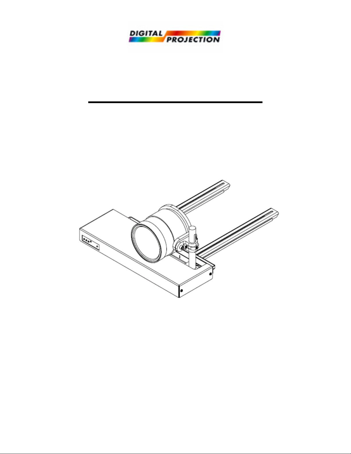
TheaterScope System
DPI Part # 106-480 (HD) or 106-487 (1080p)
Installation Manual
READ ALL INSTRUCTIONS BEFORE BEGINNING INSTALLATION
2/5/2007 To contact Technical Support please call 770-420-1350 1
Page 2
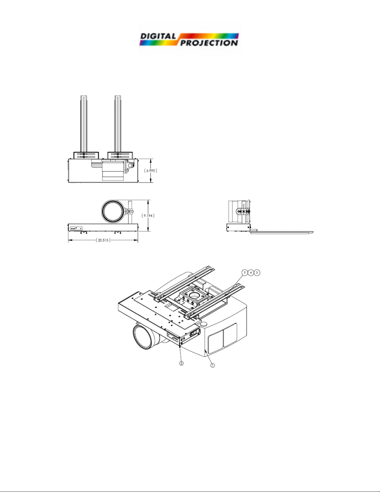
Physical Dimensions
TheaterScope System shown mounted inverted to dVision projector.
2/5/2007 To contact Technical Support please call 770-420-1350 2
Page 3

1
2
3
Operating the TheaterScope
Safety Note
Be sure to keep hands & fingers and any loose clothing away from any moving parts
Automatic mode
The TheaterScope powers-up in automatic mode. On power-up the LED flashes green multiple
times, and then turns a solid color when the unit is ready for operation.
Depending on the position of the TheaterScope, the led will be different colors.
Solid Green = Home position.
Solid Red = other limit of travel.
Solid Amber = in between limits.
The Led will blink with the Amber color while the TheaterScope is moving.
Control
You may use any of the following means to control the TheaterScope:
• Infrared Control
• RS-232 Serial / Computer Control
• Single Latching Relay
Programming the TheaterScope
Programming
Buttons
To enter Programming mode:
1. Hold down buttons 1, 2, and 3 while powering up the TheaterScope. The LED will flash
green, and then turn red to indicate that you have entered programming mode. Release all
buttons when the LED turns a solid red.
2. Test the unit by pressing buttons 2 or 3. It should move only when the button is depressed.
The TheaterScope will stop when the button is released. In manual mode the led colors are
the same as they are in automatic mode.
3. The TheaterScope has a default setting of operating on a LENS-CENTERED projector (i.e.
Mercury, Titan). Only if your projector is LENS-LEFT (i.e. dVision), make the
following programming change:
• While in programming mode, hold button 1 for 10 seconds until the led flashes, then
release button 1. This will reverse the direction of the TheaterScope to function
properly with your LENS-LEFT projector.
2/5/2007 To contact Technical Support please call 770-420-1350 3
Page 4

Set the SHOW position.
POS 1
POS 2
1. Send the TheaterScope to its Home position by using button 3. The Home position will be
indicated by the green LED. If the LED turns red, the TheaterScope is at the wrong end. Move
the TheaterScope to its Home position.
2. Move the TheaterScope to the Show position by using button 2. If you go past the desired
show position use button 3 to go back.
3. To program the SHOW position, press and hold button 1 then press button 2. Release
button 2, and then release button 1.
4. To return to automatic mode, cycle power to the TheaterScope.
Note: The 3 buttons are only used to program the TheaterScope. They have no functionality
in automatic mode.
In Automatic mode:
5. Use your desired means of control to send the TheaterScope to its home position.
6. Test the operation of the TheaterScope to verify it has accepted your program.
7. Press the SHOW button. The TheaterScope should move to the desired show position. If the
TheaterScope does not travel to the desired position, repeat this programming process.
If using the switch method of control. On power-up, the TheaterScope may first go to the show
limit, but it will then move to the home position. After traveling to the home position, the
TheaterScope will travel to the desired show position. If it does not travel to the desired show
position, repeat this process.
Infrared Control
The Position 1 button sends the TheaterScope to its HOME position
The Position 2 button sends the TheaterScope to the desired SHOW position
2/5/2007 To contact Technical Support please call 770-420-1350 4
Page 5

LED
Direction of travel
Wiring Connections
Note: The 9 pin D-Sub connector is used for wiring either Single Latching Relay or RS-232.
Serial Control
Transmit Commands Serial Responses
A Goto Home R Received Command
B Goto Show X Bad Command
C Stop M Moving
Q Query D At Home
E At Show
F Stopped between Home and Show
Controller/DB9 Female ALS / DB9 Male
Function Pin # Pin # Function
Receive 2 2 Transmit
Transmit 3 3 Receive
Ground 5 5 Ground
Single Latching Relay
Note: Be sure to program the show position for the lens before connecting the single latching
relay. The TheaterScope uses pins 5, 6 & 7 of the DB9 connector for Single Latching Relay and
will not function under RS232 or Infrared Control.
Note: The enable must be closed for the switch to operate.
The switch sends the unit to its HOME position if closed.
The switch sends the unit to its SHOW position if open.
Controller/DB9 Female ALS / DB9 Male
Function Pin # Pin # Function
Ground 5 5 Ground
Contact Enable 6 6 Contact Enable
Switch 7 7 Switch
Pins 1, 4, 8 & 9 are non-functional
Mounting
Rails
Power
Switch
Power
Cord
2/5/2007 To contact Technical Support please call 770-420-1350 5
D-Sub 9
Connector
Programming
Buttons
IR
Receiver
 Loading...