

Page 1
The POWER display range of
SUPER-HIGH-BRIGHTNESS DIGITAL VIDEO PROJECTORS
POWER 2v, POWER 4dv and POWER 5dv
USER MANUAL
Revision E - 28/01/98
Page 2

Page 3

Directives covered by this Declaration
89/336/EEC Electromagnetic Compatibility Directive, amended by 92/31/EEC & 93/68/EEC
73/23/EEC Low Voltage Equipment Directive, amended by 93/68/EEC
Products covered by this Directive
Large Screen Projector types POWER 2v, POWER 4dv and POWER 5dv
Basis on which Conformity is being declared
The products identified above comply with the protection requirements of the above EU
directives, and the manufacturer has applied the following standards:-
BS EN 50081-1: 1992 EMC Generic Emission Standard for Residential, Commercial and
Light Industrial Equipment.
BS EN 50082-1: 1992 EMC Generic Immunity Standard for Residential, Commercial and
Light Industrial Equipment.
BS EN 55022: 1995 - Limits and Methods of Measurements of Radio Disturbance
Characteristics Information Technology Equipment.
BS EN 60950: 1992 - Specification for Safety of Information Technology Equipment, including Electrical Business Equipment.
The technical documentation required to demonstrate that the products meet the requirements
of the Low Voltage Directive has been compiled by the signatory below and is available for
inspection by the relevant enforcement authorities. The CE mark was first applied in 1997.
Signed:
Authority: D.J. Quinn, Product Development Director
Date: 29th April 1997
Attention!
The attention of the specifier, purchaser, installer, or user is drawn to special measures and
limitations to use which must be observed when these products are taken into service to
maintain compliance with the above directives. Details of these special measures are
available on request, and are also contained in the product manuals.
Declaration of Conformity
LBV00018; Revision E - 28/01/98
Page 4

From time to time revisions will be issued to this manual. To maintain a correct and
up to date copy of the manual it is important that the instructions given in revision
notices are carried out.
The person carrying out the revision should complete the table below.
Revision No Revision Details Date Revised
Revision Record
LBV00018; Revision E - 28/01/98
Page 5

Please read the following before proceeding
The Digital Projection POWER displays are Super-High-Brightness Video Projectors
capable of producing images of superb brightness and clarity with the minimum of
set-up time and operating support. The User Interface via the On Screen Display, is
designed to allow the novice user rapid access to basic projector operation while
providing the expert with the ability to tailor the performance to his exact
requirements.
An Outline of Contents is given overleaf which provides an overview of the five
sections, A to E, in this manual and lists all the major topics covered along with
their location. This outline allows the user to direct themselves to the appropriate
section of this manual where a detailed contents page will provide the exact location
of the topic required. Section identifiers are also provided on the outside edge of the
pages to allow the quick location of individual sections.
The user is strongly recommended to read Section A: Overview before unpacking
or switching on the projector, paying particular attention to the safety warnings on
pages A—3 and A—4.
Disclaimer Digital Projection makes a sincere effort to ensure accuracy and quality of it's published materials;
however, no warranty, expressed or implied, is provided. Digital Projection disclaims any direct or indirect damages
resulting from the use of any information in this manual.
Introduction
Introduction
INTRODUCTION
LBV00018; Revision E - 28/01/98
Page 6

Introduction
INTRODUCTION
LBV00018; Revision E - 28/01/98
Digital Projection Limited,
Greenside Way, Middleton, Manchester M24 1XX, UK.
Registered in England No. 2207264, Registered Office: As Above
Tel: +44 (0) 161 947 3300
Fax: +44 (0) 161 684 7674
E-Mail: enquiries@digitalprojection.co.uk
Web Site: www.digitalprojection.co.uk
Digital Projection Inc.
55 Chastain Road, Suite 115, Kennesaw, GA 30144. USA
Tel: (USA) 770 420 1350
Fax: (USA) 770 420 1360
E-Mail: powerinfo@digitalprojection.com
Web Site: www.digitalprojection.com
DMD and Digital Micromirror Device are trademarks of Texas Instruments Incorporated.
Page 7

Section A: Overview
Packaging....................................................................AÑ1
Safety Advice...............................................................AÑ2
Initial Preparation ........................................................AÑ5
Components.................................................................AÑ8
Section B: System Installation
Installation Guidelines ..................................................BÑ1
Switching On...............................................................BÑ17
Section C: System Operation
Remote Control - Overview..........................................CÑ1
LED Indicators...............................................................CÑ6
Menu Operation...........................................................CÑ7
Main Menu - Overview ..............................................CÑ11
Channel Set-up Function ...........................................CÑ13
Image Mode...............................................................CÑ28
User Preferences .........................................................CÑ29
Test Patterns ...............................................................CÑ31
Projector Status ...........................................................CÑ33
Set Projector Address..................................................CÑ35
Add Computer ...........................................................CÑ36
Applying a New Signal Source..................................CÑ42
Adjusting the Displayed Image .................................CÑ45
Addressing Multiple Projectors...................................CÑ48
Introduction
Outline of Contents
INTRODUCTION
LBV00018; Revision E - 28/01/98
Page 8

Section C: System Operation
Computer Control.......................................................CÑ49
Switcher Operation.....................................................CÑ54
Section D: Advanced User Information
Screen Illuminance ......................................................DÑ1
DMDª Operation and Usage ......................................DÑ2
Operation Flowcharts...................................................DÑ4
Lenses .........................................................................DÑ14
Technical Specification ..............................................DÑ44
Section E: Fault Finding & Maintenance
Trouble Shooting ...........................................................EÑ1
Maintenance ................................................................EÑ4
Appendix
Quick Set-up Reference.......................................................i
Menu System Review ........................................................iii
Glossary.............................................................................vi
Introduction
INTRODUCTION
LBV00018; Revision E - 28/01/98
Page 9

Packaging .........................................................................AÑ1
Projector Packaging.....................................................AÑ1
Lens Packaging ...........................................................AÑ1
Safety Advice ....................................................................AÑ2
Compliance with Regulatory Bodies ...........................AÑ2
Safety Warnings...........................................................AÑ3
Initial Preparation .............................................................AÑ5
Pre-Installation Check ..................................................AÑ5
Remote Control Unit - Battery Installation ...................AÑ6
Remote Receiver..........................................................AÑ7
Components ......................................................................AÑ8
Projector Case ..............................................................AÑ8
LED Indicators ..............................................................AÑ9
Arc Lamp .....................................................................AÑ9
Optics .........................................................................AÑ10
Lenses.........................................................................AÑ10
Electronics ..................................................................AÑ11
Digital Micromirror Devicesª ....................................AÑ11
Analogue Input Board ...............................................AÑ12
Power Supplies ...........................................................AÑ13
Cooling System ..........................................................AÑ13
Air Filters.....................................................................AÑ14
Overview
Section A: Overview
OVERVIEW
LBV00018; Revision E - 28/01/98
Page 10

Components
Remote Control ..........................................................AÑ14
Remote Receiver ........................................................AÑ15
Overview
OVERVIEW
LBV00018; Revision E - 28/01/98
Page 11

Projector Packaging
To provide protection during transportation, the projector is surrounded with foam,
placed on a wooden palette and enclosed within a sturdy fibreboard carton. The
package is then secured with banding and fastening clips.
To unpack the projector, first release the two fastening clips and remove the
banding. Next, using the finger holes provided, gently lift off the outer cover of the
carton. Do not open the tape seal on the top of the cover.
Lift out the carton containing the peripheral equipment and place to one side, then
remove the two sections of protective foam.
Due to the projector's weight, four people are required to lift the projector, one at
each corner using the finger grips on the underside. The purchaser is reminded to
use good practice in lifting the projector to avoid risk of back injury.
All packaging should be retained to provide maximum protection during future
shipping of the projector. To repack the projector, reverse the above procedure.
Contained within the packaging will be:
1 x POWER display Projector 1 x Remote Control Unit
1 x AC Power Cable 1 x User Manual
4 x Projector Mounting Feet
Should any of the above components be absent, please contact the dealer who
supplied the projector, or Digital Projection Limited (Digital Projection Inc. if in
North America) immediately.
Lens Packaging
Lenses are supplied as individual items and the packaging may differ depending on
the version ordered. Please refer to the instructions supplied with your lens.
AÑ1
Overview
Packaging
OVERVIEW
LBV00018; Revision E - 28/01/98
Page 12

Compliance with Regulatory Bodies
The POWER 2v, POWER 4dv and POWER 5dv have been built to comply with
IEC950 and UL 1950, the International safety standards for information technology
and electrical business equipment. These standards impose stringent safety
requirements on the construction and operation to prevent energy hazards, access to
live parts and the risk of electric shock. The safety standards also provide
regulations on internal and external temperature increases, radiation levels,
mechanical stability and strength, enclosure construction and fire protection.
The POWER 2v, POWER 4dv and POWER 5dv have been tested and found to comply
with the limits for a class A digital device, pursuant with Part 15 of the Federal
Communication Commission rules. These limits are designed to provide reasonable
protection against harmful interference when the equipment is operated in a
commercial environment. This equipment generates, uses, and can radiate radio
frequency energy and, if not installed and used in accordance with the instruction
manual, may cause harmful interference to radio communications. Operation of this
equipment in a residential area may cause harmful interference, in which case the
user will be responsible for correcting any interference.
AÑ2
Overview
Safety Advice
OVERVIEW
LBV00018; Revision E - 28/01/98
Page 13

Safety Warnings
All the safety warning in this manual are in bold italic type and can be identified by
the symbol shown on the left.
A list containing all the warnings is given below. It is recommended that time is
taken to study these before installing or operating the projector.
The customer should never attempt to disassemble the lamp from its housing or to
dispose of it other than by returning it to Digital Projection.
The condenser system is precisely aligned in the factory and no attempt should be
made by the customer to adjust it.
Only use lenses specified in this manual or recommended by Digital Projection.
High Voltage, Danger of Death - the arc lamp power supply has a 30kV strike
pulse mechanism, which is active during lamp switch-on.
Do not move or tamper with any seals or ducting panels on the projector or the
air flow could be disrupted and cause the projector to overheat. Always keep the
air inlets and outlets clear of any obstruction.
If the Air Filters are not regularly replaced the air flow inside the projector could
be disrupted and cause overheating. Overheating may lead to the projector shutting down during operation
The projector should never, under any circumstances, be mounted or operated
upside down or at an angle greater than 90° from horizontal.
Never mount the projector near air conditioning or heating ducts, electrical
wiring or any materials which could be affected by the projector's operational
heat i.e. polystyrene ceiling tiles etc.
AÑ3
Overview
OVERVIEW
LBV00018; Revision E - 28/01/98
Page 14

The projector is designed to be lifted using the finger grips on the base. Do not
attempt to lift the projector by holding the front or side covers.
Care should be taken when attaching the projector feet so that the projector does
not rest on its feet at an angle.
Never operate the projector with the cover removed, the arc lamp power supply
has a 30kV strike pulse mechanism, which is active during lamp switch-on.
NEVER look into the lamp housing, or attempt to remove the lamp from its
housing when the lamp is on.
Before attempting to remove any of the projector's covers, you must turn off the
projector and disconnect from the mains supply.
OTHER IMPORTANT SAFETY CONSIDERATIONS
In order to ensure that correct internal airflows are maintained, and that the
projector complies with Electro-Magnetic Compatibility requirements, it should
always be operated with all of it's covers in place.
Ensure that nothing can be spilled on, or dropped inside the projector. If this does
happen, switch off and unplug the mains supply immediately. Do not operate the
projector again until it has been checked by qualified service personnel.
The projector must always be mounted in a manner which ensures free flow of air
into its air inlets and unimpeded evacuation of the hot air exhausted from its
cooling system. The air exit duct at the top of the projector can become hot during
operation and should not be touched by the operator. Heat sensitive materials
should not be placed in the path of the exhausted air.
Do not move or tamper with any seals or ducting panels on the projector or the
air flow could be disrupted and cause the projector to overheat. Always keep the
air inlets and outlets clear of any obstruction.
AÑ4
Overview
OVERVIEW
LBV00018; Revision E - 28/01/98
Page 15

Pre-Installation Check
Before mounting the projector in its intended location, the following pre-installation
routine must be performed:
1. Install the projector lens.
2. Ensure all the air flow inlet and outlet ducts are clear from obstruction.
3. Insert the power cord securely into the socket on the rear panel of the projector
and connect to an appropriate mains supply (refer to the specification label at
the rear of projector).
4. Switch on the projector and wait for approximately 30 seconds.
5. Check air is flowing out of the exit ducts on the top and left hand side of the
projector.
6. With the screen or a wall illuminated, confirm the Menu System is operational
by pressing OSD ON then MENU on remote control (a main menu should be
clearly visible).
7. Turn the lamp off by depressing the LAMP OFF button on the remote control
for two seconds.
8. Power down the projector and disconnect from the mains supply.
9. Continue with the system installation.
AÑ5
Overview
Initial Preparation
OVERVIEW
LBV00018; Revision E - 28/01/98
Page 16
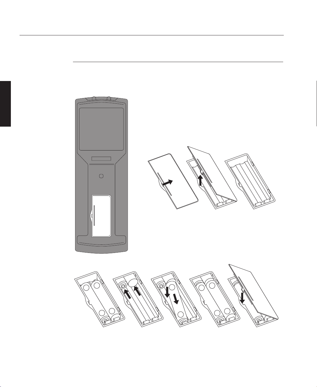
Remote Control Unit - Battery Installation
The Remote Control Unit can be powered by 4 AAA (HP16/RO3/LR03) alkaline
batteries or by direct connection to the projector via a remote receiver.
The battery compartment is located on the back of the
Remote Control. To remove the compartment cover,
insert a finger-nail into the recess provided to the right
of the cover and push to the right. While pushing to the
right, lift out the left hand side of the cover.
Insert the first two new batteries as shown below and
slide them to the back of the compartment. Insert the
remaining two batteries by pivoting them against the
electrical contacts and pushing down into place.
When the batteries are securely in place, replace the cover by aligning the stays on
the right hand side and pushing down the left hand side until it 'clicks' into place.
AÑ6
Overview
OVERVIEW
LBV00018; Revision E - 28/01/98
+
-
-
+
-
+
+
-
-
+
Page 17
Remote Receiver
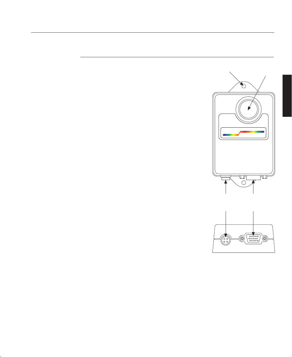
The optional remote receiver acts as a relay between
the remote control and the projector and is useful for
installations where the Infra Red signal from the
remote cannot reach the sensors on the projector.
The Infra Red signals from the remote control are
picked up by the IR receiver on the front of the
remote receiver and are relayed to the projector via
the 15 way high density 'D' style connector on the
underside of the unit.
The remote receiver also allows direct cabling (hard
wiring) of the remote control unit via a 4 way
'LEMO' connector. When used in this way, the
remote control does not require batteries and the IR
receiver on the remote receiver is disabled.
Hard wiring has the advantage of allowing control
of the projector from a greater distance: The cable
from the remote control to the remote receiver can
be up to 10m (33ft) in length and the cable
connecting the remote receiver to the projector can
be up to 60m (200ft) long.
When hard wiring, the remote control unit must
be connected to the remote receiver before the
remote receiver is connected to the projector. If the
connections are not made in this order the remote
receiver fuse will trip and the remote receiver will
have to be disconnected for approximately one
minute before reconnecting in the correct manner.
For further information on remote receiver wiring,
see Cables and Connections, D—39.
AÑ7
Overview
OVERVIEW
LBV00018; Revision E - 28/01/98
DIGITAL
PROJECTION
4 Way
'LEMO'
Connector
15 Way
HD 'D'
Connector
Mounting
Hole
Infra Red
Receiver
Page 18
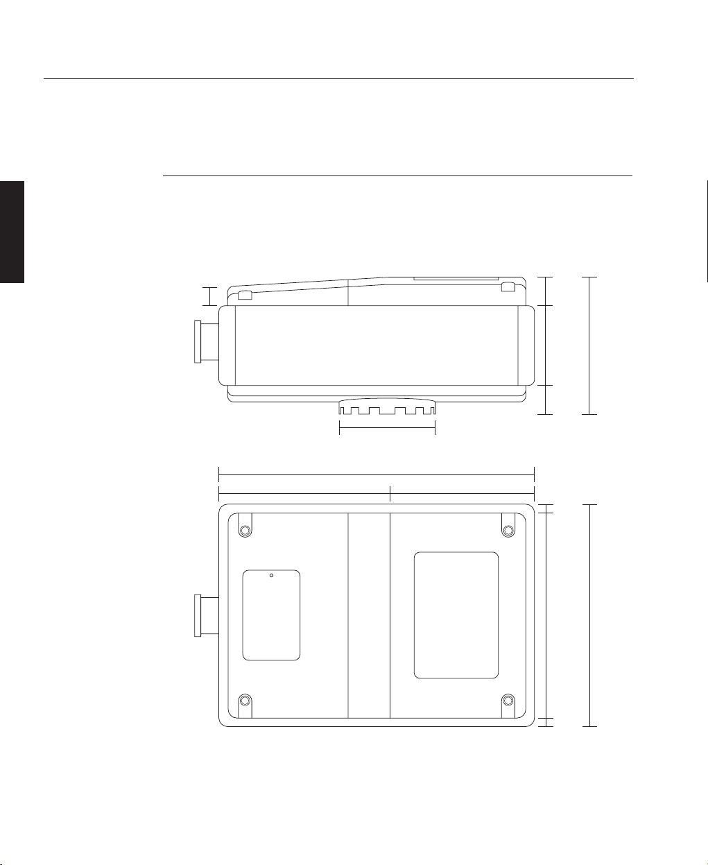
Projector Case
The projector case has an aluminium die cast chassis with rigid corner posts and
cross members to support the side and top covers. The integral mounting plate
provides for easy mounting onto a table, stand or cradle.
AÑ8
Overview
Components
OVERVIEW
LBV00018; Revision E - 28/01/98
55.2mm
(2.17")
300mm (11.81")
975mm (38.38")
525mm (20.67") 450mm (17.72")
83mm
(3.27")
235mm
(9.25")
85mm
(3.34")
30mm
(1.18")
403mm
(15.86")
600mm
(23.62")
30mm
(1.18")
660mm
(25.98")
Page 19
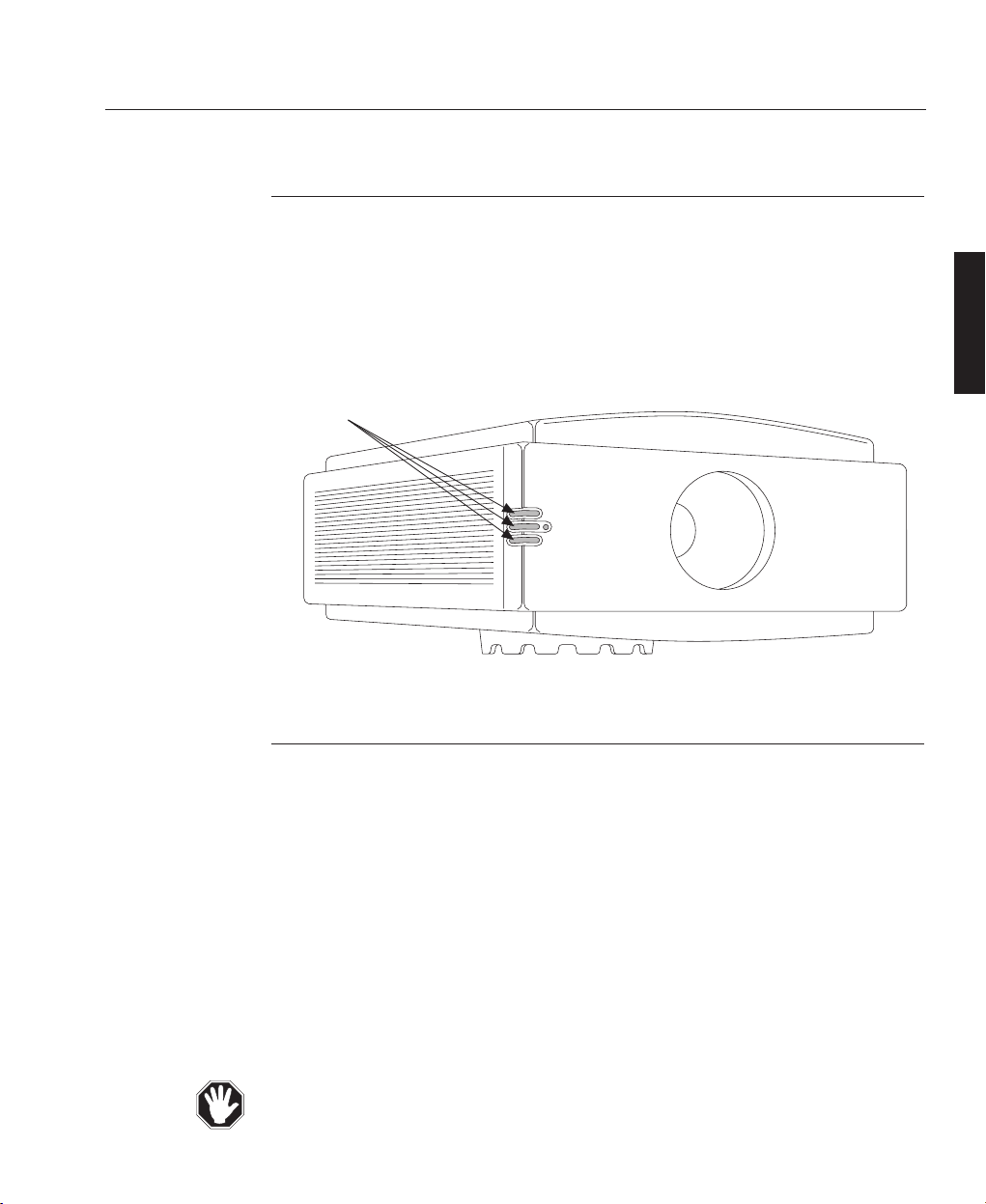
LED Indicators
There are 3 Light Emitting Diodes (top - red, middle - green, bottom - red) at the
front of the case which indicate the status of the projector. The top red LED is used
to indicate that power is applied to the projector and that it is turned on. The middle
green LED indicates normal operation and flashes when the projector is receiving a
signal from the remote control unit. The bottom red LED indicates that the lamp has
failed. For further information see System Operation, C—6.
Arc Lamp
The projector uses a specialised, high pressure xenon arc lamp designed to operate
in conjunction with Digital Projection's optical condenser system and specialised
power supply unit. The lamp achieves maximum brightness immediately following
strike and is designed for an operating life of greater than 750 hours.
The operator is advised where possible to switch off the lamp using the 'LAMP
OFF' button on the remote control, and allow the cooling system to run on for two
minutes before switching off the mains supply.
The lamp is contained in a special safety housing to dissipate heat and to make
changing the lamp as easy as possible (see Fault Finding and Maintenance, E—6).
The customer should never attempt to disassemble the lamp from its housing or to
dispose of it other than by returning it to Digital Projection.
AÑ9
Overview
OVERVIEW
LBV00018; Revision E - 28/01/98
LEDs
Page 20

Optics
The lamp faces downwards onto a 'cold mirror' which directs the light beam into a
condenser. A prism then splits the concentrated beam from the condenser into red,
green and blue light using dichroic filters and directs the light onto separate
DMDs™. The images produced by the three DMDs™ are then combined by the
prism to form a full colour image and directed into the lens for projection.
The condenser is precisely aligned in the factory. If it is moved there could be a
reduction in light output and image display quality.
Lenses
There are seven lenses available for the POWER display projectors which cater for
all foreseen user requirements. The lenses are identified by their ratio of 'Throw
Distance' to screen width, where 'Throw Distance' is the distance the projector must
be positioned from the screen to display an optimum image (see B—4, Positioning
the Projector).
At present, there are four fixed ratio lenses available for the projector (1.27:1, 3:1,
5:1 and 7:1), two zoom lenses; 1.5:1 to 3:1 and 3:1 to 7:1 respectively and an
SVGA Ultra Wide Angle lens.
1.27:1 is the accurate ratio for the lens marked as 1.2 and this ratio should be
used for any calculations.
The lens required will be dependant on the size of the screen, the 'Throw Distance'
available and the aspect ratios of the images to be displayed. If unsure which lens
would best suit your requirements, consult your dealer.
Only use lenses specified in this manual or recommended by Digital Projection.
AÑ10
Overview
OVERVIEW
LBV00018; Revision E - 28/01/98
Page 21
Electronics
The main electronic components of the projector are the Analogue Input Board,
Digital Processing Card, Formatter Card and the three Display Boards (each of
which contains a Digital Micromirror Device™).
The Analogue Input Board, situated at the rear of the projector, converts analogue
inputs to digital signals and routes them to the digital processing card.
The Digital Processing Card stores the channel configurations and any on screen
adjustments such as brightness, contrast etc. These settings are applied to the
incoming signal for transfer to the Formatter Card.
The Formatter Card translates the digital signal into a format that the Digital
Micromirror Devices™ can read.
Digital Micromirror Devicesª
A Digital Micromirror Device™ (DMD™) is a digital light modulator fabricated
from moving aluminum mirrors. Each mirror, which acts as a pixel, is suspended
between two posts by a thin torsion hinge and can be tilted to the left to produce
a bright pixel or to the right for a dark pixel. There are three DMDs™ in the
projector, one for each of the primary colours, each containing 508,800 mirrors
arranged in a 848 x 600 array.
AÑ11
Overview
OVERVIEW
LBV00018; Revision E - 28/01/98
Casing
Inactive Pixels
848 x 600 Array
Light Shield
Page 22
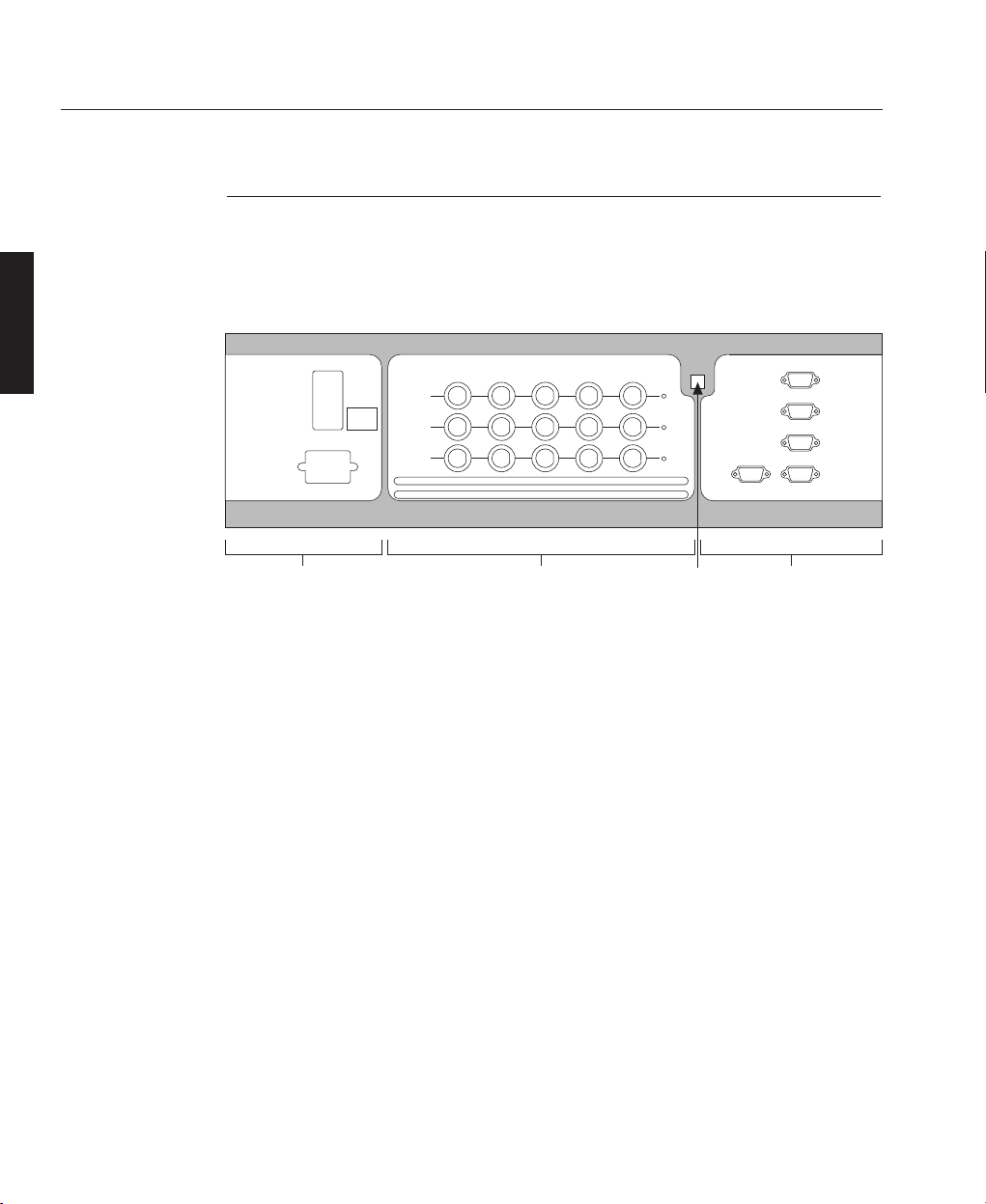
Analogue Input Board
The Analogue Input Board located at the rear of the projector provides all the
required connections for video, computer, audio and remote control inputs. The
input board is split in three main sections - Power, Source and Control (see below).
POWER
Mains Input - For connection of 200 - 240 V ac 50 - 60 Hz.
Circuit Breaker (On/Off Control) - Combined on/off switch and circuit isolator
(in case of system overload).
SOURCE
Inputs 1, 2, 3 - Each of these inputs can be configured for different signal sources.
RGB, Hs Vs and Hs+Vs are used with a computer input, Composite/G is used with
a composite signal (such as NTSC), C and Y (S-VIDEO) are used with a VHS
video player and Y Pr Pb are used with Betacam or component sources.
Select LED's - The input card LED's indicate which input should be used with the
current channel. If the projector cannot find a valid signal, the LED flashes.
AÑ12
Overview
OVERVIEW
LBV00018; Revision E - 28/01/98
POWER SOURCE CONTROL
INPUT 1
WARNING
This equipment
must be earthed
200-240V AC 16A Max
50/60 Hz
Digital Projection Limited, Manchester M24 1XX UK
Tel: +44 (0)161 681 6500 Fax: +44 (0)161 684 7674
Power
Section
INPUT 2
INPUT 3
Component
S-Video
Composite
R/Pr
G/Y
B/Pb
C
-
-
CVbs
H/HV
Y
-
-
-
Source
Section
V
-
-
Component
S-Video
Composite
Infra Red
Receiver
Ext
Remote
Video
Switcher
Audio
Switcher
Out In
Computer
Control
Section
Page 23
CONTROL
Ext Remote - Input providing direct connection with the remote receiver.
Video Switcher - Control input and output for video switcher configurations.
Audio Switcher - Future Feature, when available this connection will permit the
control of a third party 3 channel audio switcher.
Computer (In/Out) - Provides data input and output ports for computer control and
for daisy chain connector to multiple projectors.
Power supplies
The General Power Supply provides a range of low voltage rails to the electronics.
The Xenon Arc Lamp has a separate high current power supply.
High Voltage, Danger of Death - the arc lamp power supply has a 30kV strike
pulse mechanism, which is active during lamp switch-on.
Cooling System
During normal operation considerable heat is generated inside the projector,
therefore, an air cooling system is provided. This consists of a powerful fan which
draws cool air through specially designed air ducts within the case to distribute it
over the lamp and other components. The cooling system provides maximum
cooling whilst minimising noise output.
Do not move or tamper with any seals or ducting panels on the projector or the
air flow could be disrupted and cause the projector to overheat. Always keep the
air inlets and outlets clear of any obstruction.
AÑ13
Overview
OVERVIEW
LBV00018; Revision E - 28/01/98
Page 24
Air Filters
There are 5 air filters in the POWER 4dv and POWER 2v projectors, one in each side
cover and three underneath. The POWER 5dv has only the 3 air filters underneath.
All filters must be regularly checked and replaced in order to prevent the projector
from overheating.
Air filters are supplied in complete sets and it is recommended that they are
replaced at least every 3 months. All filters can be replaced without the need for
special tools and complete instructions are given on pages E—4 and E—5 of this
manual.
If the Air Filters are not regularly replaced the air flow inside the projector could
be disrupted and cause overheating. Overheating may lead to the projector
shutting down during operation
Remote Control
All the functions of the POWER display are controlled from the remote control,
which can be connected via a remote receiver to the projector. When connected via
the remote receiver, it simultaneously powers the control unit, lights the remote
controls back panel and relays commands back to the projector.
To allow the operator more flexibility the remote control can be operated by four
AAA batteries, producing infra-red signals which are detected by sensors located at
the front and rear of the projector. The remote control unit is designed to transmit
command signals to the projector from a maximum distance of 80m (266ft).
The presence of very bright fluorescent lighting or Infra Red translation systems
may saturate the projectors Infra Red receivers.
AÑ14
Overview
OVERVIEW
LBV00018; Revision E - 28/01/98
Page 25

Remote Receiver
The optional remote receiver is used to pick-up infra-red signals from the remote
control unit and relay them to the projector.and also provides a 'hard wire' interface
between the remote control and the projector.
The remote receiver is a small 75mm x 100mm x 25mm (3" x 4" x 1") matt black
box with mounting lugs on each end and an infra red sensor on the front. On the
underside there are 2 connection points:- a 15 way high density 'D' style connector
for the projector and a 4 way 'LEMO' connector for the remote control (refer to
A—7 and D—39 for more information).
AÑ15
Overview
OVERVIEW
LBV00018; Revision E - 28/01/98
Page 26

Overview
OVERVIEW
LBV00018; Revision E - 28/01/98
Page 27

Installation Guidelines .......................................................BÑ1
Screen Requirements ....................................................B
Ñ1
Positioning the Projector ................................................B
Ñ4
Mounting the Projector................................................B
Ñ12
Optional Mounting Frames ...................................... BÑ15
Switching On.....................................................................BÑ17
Signal Sources..............................................................B
Ñ17
Turning On the Lamp ..................................................B
Ñ20
Picture Display.............................................................B
Ñ20
Storing System Configurations ....................................B
Ñ22
System Installation
Section B: System Installation
INSTALLATION
LBV00018; Revision E - 28/01/98
Page 28

System Installation
INSTALLATION
LBV00018; Revision E - 28/01/98
Page 29
This installation section explains how to install the projector for optimum results.
To do this, it is necessary to determine the following:
1. The type of screen and whether front or rear projection is to be used.
2. The projector location and therefore the type of lens to be used.
3. The method of mounting for the projector.
4. The type of input source to be used with the projector.
Screen Requirements
As virtually all commercially available screens will give a pleasing image you
should choose according to your individual requirements. However, to achieve
optimum results we recommend a low gain (1.2 - 1.3), non-perforated screen for
front projection, this will keep hot spotting and light loss to a minimum whilst
providing wide viewing angles.
Regardless of the type of screen used, it is important that your screen is of sufficient
height to display the images at the aspect ratios intended to be used. Use the
following tables to check that you are able to display the full image on your screen.
If you have insufficient height, you will have to reduce the overall image size in
order to display the full image on your screen.
BÑ1
System Installation
Installation Guidelines
INSTALLATION
LBV00018; Revision E - 28/01/98
Screen Width
(metres)
2.40
3.00
3.60
4.20
4.80
6.00
10.00
4 x 3
1.80
2.25
2.70
3.15
3.60
4.50
7.50
5 x 4
1.92
2.40
2.88
3.36
3.84
4.80
8.00
8 x 5
1.5
1.87
2.25
2.62
3.00
3.75
6.25
14 x 9
1.54
1.93
2.31
2.70
3.09
3.86
6.43
16 x 9
1.35
1.69
2.02
2.36
2.70
3.38
5.63
Screen Height (metres) Needed to Display Full Image with Aspect Ratio:
Page 30
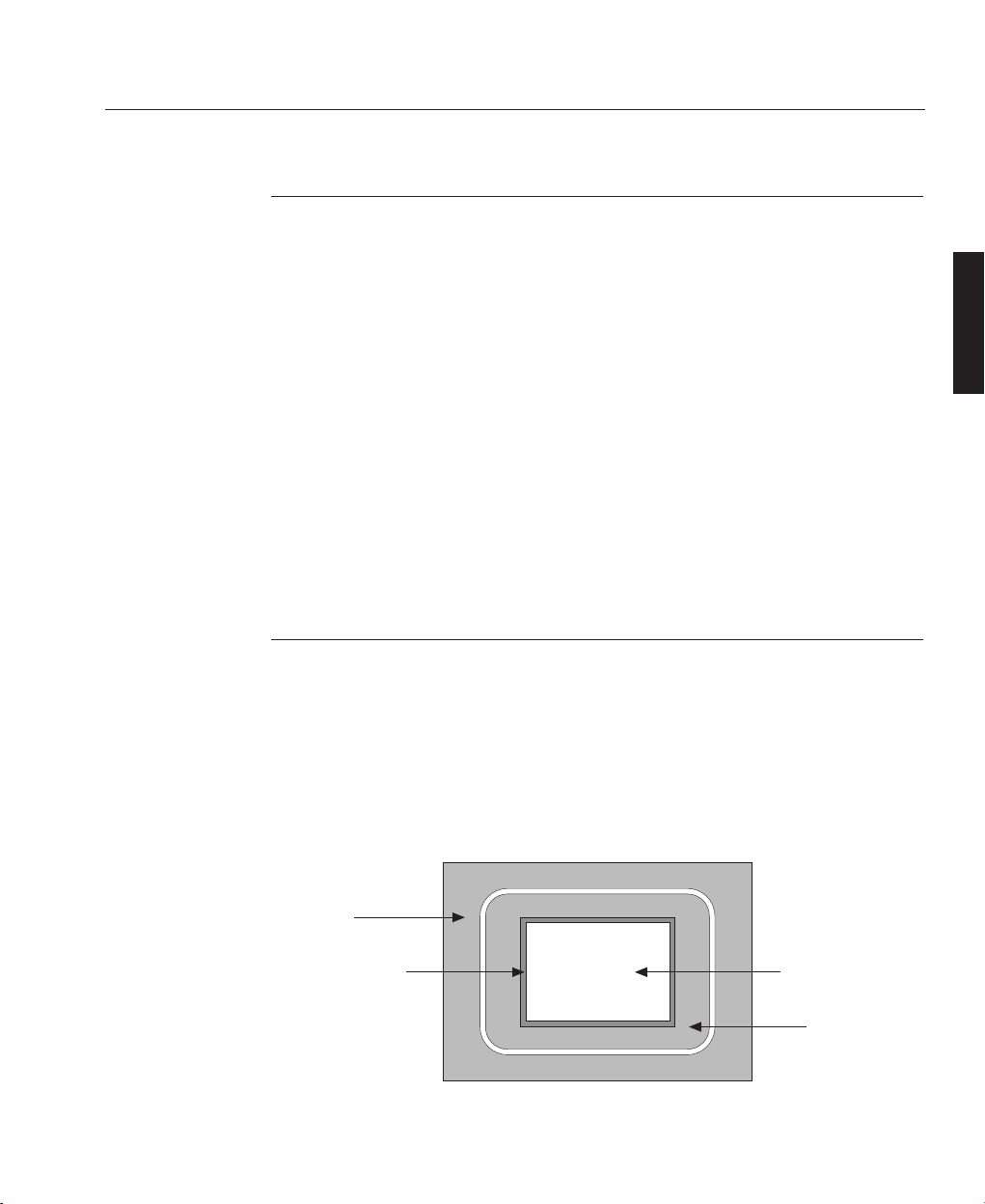
For optimum viewing, the screen should be a flat surface perpendicular to the floor.
The bottom of the screen should be 1.2m (4 feet) above the floor and the front row
of the audience should not have to look up more than 30° to see the top of the
screen (see opposite).
The distance between the front row of the audience and the screen should be at least
twice the screen height and the distance between the back row and the screen should
be a maximum of 8 times the screen height. The screen viewing area should be
within a 60° range from the face of the screen.
If you intend to use a rear projection screen you must ensure you have sufficient
distance behind the screen for the projector to be correctly located (see B—4). Rear
projection has the advantage that the projector cannot be seen and higher ambient
light levels can be tolerated. Although the image can be flipped to rear projection
using the Image Mode Menu (see system operation, C—28) and displayed without
the need for extra mirrors or equipment, it makes the installation more complicated
and advice should be sought from your local dealer before attempting an installation
in this way.
BÑ2
System Installation
INSTALLATION
LBV00018; Revision E - 28/01/98
Screen Width
(feet)
8' 0"
10' 0"
12' 0"
14' 0"
16' 0"
20' 0"
30' 0"
4 x 3
6' 0"
7' 6"
9' 0"
10' 6"
12' 0"
15' 0"
22' 6"
5 x 4
6' 5"
8' 0"
9' 7"
11' 2"
12' 10"
16' 0"
24' 0"
8 x 5
5' 0"
6' 3"
7' 6"
8' 9"
10' 0"
12' 6"
18' 9"
14 x 9
5' 2"
6' 5"
7' 9"
9' 0"
10' 8"
12' 10"
19' 4"
16 x 9
4' 6"
5' 8"
6' 9"
7' 11"
9' 0"
11' 4"
16' 11
Screen Height (feet/inches) Needed to Display Full Image with Aspect Ratio:
Page 31

BÑ3
System Installation
INSTALLATION
LBV00018; Revision E - 28/01/98
H
30°
1.2m (4 Ft)
2H
SCREEN
2H8H
60°
VIEWING AREA
AISLE
AISLEAISLE
Page 32

Positioning the Projector
Correct positioning of the projector is essential to achieve the best results. Before
deciding on the final location of the projector please ensure you read the following
information very carefully.
The projector must be situated in a clean, dry environment and away from direct
sunlight or heat. Make sure you locate the projector so that the air inlets and outlets
for the cooling system are not obstructed.
The projector should never, under any circumstances, be operated upside down or
at an angle greater than 90° from horizontal.
PROJECTOR HEIGHT
The default height for positioning the projector is at the centre of your screen.
However, depending on your lens specification, you can set the projector above or
below the centre and adjust the image using the rising front facility to maintain a
geometrically correct image.
THROW DISTANCE - FIXED RATIO LENSES
It is important to position the projector at the right distance from the screen. This
'Throw Distance' is measured from the front of the projector case to the front of the
screen and is calculated by taking into account your screen width, the type of lens
used, and the aspect ratio you intend to display.
If you intend to display images with different aspect ratios, it is recommended that
you position the projector at a distance from the screen which will allow you to
project images at the maximum aspect ratio. Failure to do so could result in larger
aspect ratio images exceeding the height and/or width of your screen. Refer to D—3
for more information on aspect ratios.
BÑ4
System Installation
INSTALLATION
LBV00018; Revision E - 28/01/98
Page 33

THROW DISTANCE - ZOOM LENSES
When using a zoom lens, exact positioning of the projector less important because
the image size can be adjusted. However, the projector must be located within the
Throw Distance range imposed by the minimum and maximum lens ratios and the
focus range of the lens.
If you intend to display images with different aspect ratios, it is recommended that
you define your own Throw Distance range from the ranges given for each Aspect
Ratio. To define the minimum value for your range, you must select the highest
minimum value from the ranges given for each aspect ratio you wish to display. To
define the maximum value for your range, you must select the lowest maximum
value from the appropriate ranges.
CALCULATING THE THROW DISTANCE
To calculate the distance between the screen and the front of the projector case
select your lens type from the following pages and use the tables provided. If your
screen size in not listed in these tables or included in the lens tables in Section D,
you will need to calculate the distance required using the following formula:-
Distance Required = (W+A) x (C÷B)
Where W = Screen Width and A,B and C are constants from the tables below.
BÑ5
System Installation
INSTALLATION
LBV00018; Revision E - 28/01/98
Lens
1.27 Fixed
3.0 Fixed
5.0 Fixed
7.0 Fixed
1.5 - 3.0 Zoom at 1.5 position
1.5 - 3.0 Zoom at 3.0 position
3.0 - 7.0 Zoom at 3.0 position
3.0 - 7.0 Zoom at 7.0 position
SVGA Ultra Wide Angle
A
-0.0037
0.0034
-0.0269
-0.0286
0.0280
0.0082
-0.0175
-0.0253
0.0467
B
0.8140
0.3520
0.2097
0.1497
0.6807
0.3532
0.3545
0.1418
0.9909
Aspect Ratio
4 x 3
5 x 4
8 x 5
14 x 9
16 x 9
C
1.06
1.1307
1.0
1.0
1.0
Page 34

1.27 : 1 LENS
Please ensure you have completely read and understood the Positioning the
Projector overview given on pages B—4 and B—5 before proceeding.
To calculate the distance in metres required between the screen and the front of the
projector case select your screen width from the following table and the aspect
ratios of the images you intend to display.
To calculate the distance in feet required between the screen and the front of the
projector case use the following table.
If you screen width is not included in the above tables refer to lenses, D—15.
Installers should allow for up to 75mm (3 inches) of projected image width
adjustment to account for lens tolerances.
BÑ6
System Installation
INSTALLATION
LBV00018; Revision E - 28/01/98
Screen Width
(metres)
2.40
3.00
3.60
4.20
4.80
6.00
4 x 3 5 x 4 8 x 5 14 x 9 16 x 9
Aspect Ratio Aspect Ratio Aspect Ratio Aspect Ratio Aspect Ratio
3.22 3.42 3.04 3.04 3.04
4.02 4.27 3.80 3.80 3.80
4.82 5.13 4.56 4.56 4.56
5.63 5.98 5.32 5.32 5.32
6.43 6.83 6.08 6.08 6.08
8.04 8.54 7.61 7.61 7.61
THROW DISTANCE (IN METRES) REQUIRED TO DISPLAY FULL IMAGE
Screen Width
(feet)
8.0
10.0
12.0
14.0
16.0
20.0
4 x 3 5 x 4 8 x 5 14 x 9 16 x 9
Aspect Ratio Aspect Ratio Aspect Ratio Aspect Ratio Aspect Ratio
10.41 11.11 9.82 9.82 9.82
13.02 13.89 12.28 12.28 12.28
15.62 16.66 14.74 14.74 14.74
18.23 19.44 17.19 17.19 17.19
20.83 22.22 19.65 19.65 19.65
26.04 27.78 24.57 24.57 24.57
THROW DISTANCE (IN FEET) REQUIRED TO DISPLAY FULL IMAGE
Page 35

3 : 1 LENS
Please ensure you have completely read and understood the Positioning the
Projector overview given on pages B—4 and B—5 before proceeding.
To calculate the distance in metres required between the screen and the front of the
projector case select your screen width from the following table and the aspect
ratios of the images you intend to display.
To calculate the distance in feet required between the screen and the front of the
projector case use the following table.
If you screen width is not included in the above tables refer to lenses, D—18.
Installers should allow for up to 75mm (3 inches) of projected image width
adjustment to account for lens tolerances.
BÑ7
System Installation
INSTALLATION
LBV00018; Revision E - 28/01/98
Screen Width
(metres)
2.40
3.00
3.60
4.20
4.80
6.00
4 x 3 5 x 4 8 x 5 14 x 9 16 x 9
Aspect Ratio Aspect Ratio Aspect Ratio Aspect Ratio Aspect Ratio
7.24 7.72 6.83 6.83 6.83
9.04 9.65 8.53 8.53 8.53
10.85 11.57 10.24 10.24 10.24
12.66 13.50 11.94 11.94 11.94
14.46 15.43 13.65 13.65 13.65
18.08 19.28 17.06 17.06 17.06
THROW DISTANCE (IN METRES) REQUIRED TO DISPLAY FULL IMAGE
Screen Width
(feet)
8.0
10.0
12.0
14.0
16.0
20.0
4 x 3 5 x 4 8 x 5 14 x 9 16 x 9
Aspect Ratio Aspect Ratio Aspect Ratio Aspect Ratio Aspect Ratio
24.10 25.71 22.74 22.74 22.74
30.12 32.13 28.42 28.42 28.42
36.15 38.56 34.10 34.10 34.10
42.17 44.98 39.78 39.78 39.78
48.19 51.40 45.46 45.46 45.46
60.24 64.25 56.83 56.83 56.83
THROW DISTANCE (IN FEET) REQUIRED TO DISPLAY FULL IMAGE
Page 36

5 : 1 LENS
Please ensure you have completely read and understood the Positioning the
Projector overview given on pages B—4 and B—5 before proceeding.
To calculate the distance in metres required between the screen and the front of the
projector case select your screen width from the following table and the aspect
ratios of the images you intend to display.
To calculate the distance in feet required between the screen and the front of the
projector case use the following table.
If you screen width is not included in the above tables refer to lenses, D—21.
Installers should allow for up to 75mm (3 inches) of projected image width
adjustment to account for lens tolerances.
BÑ8
System Installation
INSTALLATION
LBV00018; Revision E - 28/01/98
Screen Width
(metres)
2.40
3.00
3.60
4.20
4.80
6.00
4 x 3 5 x 4 8 x 5 14 x 9 16 x 9
Aspect Ratio Aspect Ratio Aspect Ratio Aspect Ratio Aspect Ratio
12.00 12.80 11.32 11.32 11.32
15.03 16.03 14.18 14.18 14.18
18.06 19.27 17.04 17.04 17.04
21.09 22.50 19.90 19.90 19.90
24.13 25.74 22.76 22.76 22.76
30.19 32.21 28.48 28.48 28.48
THROW DISTANCE (IN METRES) REQUIRED TO DISPLAY FULL IMAGE
Screen Width
(feet)
8.0
10.0
12.0
14.0
16.0
20.0
4 x 3 5 x 4 8 x 5 14 x 9 16 x 9
Aspect Ratio Aspect Ratio Aspect Ratio Aspect Ratio Aspect Ratio
40.30 42.99 38.02 38.02 38.02
50.41 53.77 47.56 47.56 47.56
60.52 64.56 57.10 57.10 57.10
70.63 75.34 66.63 66.63 66.63
80.74 86.12 76.17 76.17 76.17
100.96 107.69 95.25 95.25 95.25
THROW DISTANCE (IN FEET) REQUIRED TO DISPLAY FULL IMAGE
Page 37

7 : 1 LENS
Please ensure you have completely read and understood the Positioning the
Projector overview given on pages B—4 and B—5 before proceeding.
To calculate the distance in metres required between the screen and the front of the
projector case select your screen width from the following table and the aspect
ratios of the images you intend to display.
To calculate the distance in feet required between the screen and the front of the
projector case use the following table.
If you screen width is not included in the above tables refer to lenses, D—24.
Installers should allow for up to 75mm (3 inches) of projected image width
adjustment to account for lens tolerances.
BÑ9
System Installation
INSTALLATION
LBV00018; Revision E - 28/01/98
Screen Width
(metres)
2.40
3.00
3.60
4.20
4.80
6.00
4 x 3 5 x 4 8 x 5 14 x 9 16 x 9
Aspect Ratio Aspect Ratio Aspect Ratio Aspect Ratio Aspect Ratio
16.79 17.91 15.84 15.84 15.84
21.04 22.44 19.85 19.85 19.85
25.29 26.97 23.86 23.86 23.86
29.54 31.51 27.87 27.87 27.87
33.79 36.04 31.87 31.87 31.87
42.28 45.10 39.89 39.89 39.89
THROW DISTANCE (IN METRES) REQUIRED TO DISPLAY FULL IMAGE
Screen Width
(feet)
8.0
10.0
12.0
14.0
16.0
20.0
4 x 3 5 x 4 8 x 5 14 x 9 16 x 9
Aspect Ratio Aspect Ratio Aspect Ratio Aspect Ratio Aspect Ratio
56.44 60.21 53.25 53.25 53.25
70.61 75.31 66.61 66.61 66.61
84.77 90.42 79.97 79.97 79.97
98.93 105.52 93.33 93.33 93.33
113.09 120.63 106.69 106.69 106.69
141.41 150.84 133.41 133.41 133.41
THROW DISTANCE (IN FEET) REQUIRED TO DISPLAY FULL IMAGE
Page 38

1.5-3 : 1 ZOOM LENS
Please ensure you have completely read and understood the Positioning the
Projector overview given on pages B—4 and B—5 before proceeding.
To calculate which Throw Distance ranges (in metres) are applicable to your
installation, select your screen width from the following table and the aspect ratios
of the images you intend to display.
To calculate the Throw Distance ranges (in feet) required between the screen and
the front of the projector case use the following table.
If you screen width is not included in the above tables refer to lenses, D—27.
Installers should allow for up to 75mm (3 inches) of projected image width
adjustment to account for lens tolerances.
BÑ10
System Installation
INSTALLATION
LBV00018; Revision E - 28/01/98
Screen Width
(metres)
2.40
3.00
3.60
4.20
4.80
6.00
4 x 3 5 x 4 8 x 5 14 x 9 16 x 9
Aspect Ratio Aspect Ratio Aspect Ratio Aspect Ratio Aspect Ratio
3.78 - 7.23 4.03 - 7.71 3.57 - 6.82 3.57 - 6.82 3.57 - 6.82
4.72 - 9.03 5.03 - 9.63 4.45 - 8.52 4.45 - 8.52 4.45 - 8.52
5.65 - 10.83 6.03 - 11.55 5.33 - 10.22 5.33 - 10.22 5.33 - 10.22
6.58 - 12.63 7.02 - 13.47 6.21 - 11.91 6.21 - 11.91 6.21 - 11.91
7.52 - 14.43 8.02 - 15.39 7.09 - 13.61 7.09 - 13.61 7.09 - 13.61
9.39 - 18.03 10.01 - 19.23 8.86 - 17.01 8.86 - 17.01 8.86 - 17.01
THROW DISTANCE (IN METRES) REQUIRED TO DISPLAY FULL IMAGE
Screen Width
(feet)
8.0
10.0
12.0
14.0
16.0
20.0
4 x 3 5 x 4 8 x 5 14 x 9 16 x 9
Aspect Ratio Aspect Ratio Aspect Ratio Aspect Ratio Aspect Ratio
12.50 - 24.03 13.33 - 25.64 11.79 - 22.67 11.79 - 22.67 11.79 - 22.67
15.62 - 35.04 16.66 - 32.04 14.73 - 28.34 14.73 - 28.34 14.73 - 28.34
18.73 - 36.04 19.98 - 38.44 17.67 - 34.00 17.67 - 34.00 17.67 - 34.00
21.84 - 42.04 23.30 - 44.84 20.61 - 39.66 20.61 - 39.66 20.61 - 39.66
24.94 - 48.04 26.62 - 51.25 23.55 - 45.32 23.55 - 45.32 23.55 - 45.32
31.19 - 60.05 33.27 - 64.05 29.42 - 56.65 29.42 - 56.65 29.42 - 56.65
THROW DISTANCE (IN FEET) REQUIRED TO DISPLAY FULL IMAGE
Page 39

3-7 : 1 ZOOM LENS
Please ensure you have completely read and understood the Positioning the
Projector overview given on pages B—4 and B—5 before proceeding.
To calculate which Throw Distance ranges (in metres) are applicable to your
installation, select your screen width from the following table and the aspect ratios
of the images you intend to display.
To calculate the Throw Distance ranges (in feet) required between the screen and
the front of the projector case use the following table.
If you screen width is not included in the above tables refer to lenses, D—33.
Installers should allow for up to 75mm (3 inches) of projected image width
adjustment to account for lens tolerances.
BÑ11
System Installation
INSTALLATION
LBV00018; Revision E - 28/01/98
Screen Width
(metres)
2.40
3.00
3.60
4.20
4.80
6.00
4 x 3 5 x 4 8 x 5 14 x 9 16 x 9
Aspect Ratio Aspect Ratio Aspect Ratio Aspect Ratio Aspect Ratio
7.12 - 17.00 7.60 - 18.13 6.72 - 16.03 6.72 - 16.03 6.72 - 16.03
8.92 - 21.29 9.51 - 22.71 8.41 - 20.09 8.41 - 20.09 8.41 - 20.09
10.71 - 25.59 11.43 - 27.29 10.11 - 24.14 10.11 - 24.14 10.11 - 24.14
12.51 - 29.88 13.34 - 31.87 11.80 - 28.19 11.80 - 28.19 11.80 - 28.19
14.30 - 34.17 15.25 - 36.45 13.49 - 32.24 13.49 - 32.24 13.49 - 32.24
17.89 - 42.76 19.08 - 45.61 16.88 - 40.34 16.88 - 40.34 16.88 - 40.34
THROW DISTANCE (IN METRES) REQUIRED TO DISPLAY FULL IMAGE
Screen Width
(feet)
8.0
10.0
12.0
14.0
16.0
20.0
4 x 3 5 x 4 8 x 5 14 x 9 16 x 9
Aspect Ratio Aspect Ratio Aspect Ratio Aspect Ratio Aspect Ratio
23.87 - 57.08 25.46 - 60.88 22.52 - 53.85 22.52 - 53.85 22.52 - 53.85
29.85 - 71.39 31.84 - 76.15 28.18 - 67.35 28.18 - 67.35 28.18 - 67.35
35.83 - 85.71 38.12 - 91.42 33.80 - 80.86 33.80 - 80.86 33.80 - 80.86
41.81 - 100.02 44.60 - 106.69 39.44 - 94.36 39.44 - 94.36 39.44 - 94.36
47.79 - 114.34 20.98 - 121.96 45.08 - 107.86 45.08 - 107.86 45.08 - 107.86
59.75 - 142.97 63.73 - 152.20 56.37 - 134.87 56.37 - 134.87 56.37 - 134.87
THROW DISTANCE (IN FEET) REQUIRED TO DISPLAY FULL IMAGE
Page 40

SVGA ULTRA WIDE ANGLE LENS
Please ensure you have completely read and understood the Positioning the
Projector overview given on pages B—4 and B—5 before proceeding.
To calculate which Throw Distance ranges (in metres) are applicable to your
installation, select your screen width from the following table and the aspect ratios
of the images you intend to display.
To calculate the Throw Distance ranges (in feet) required between the screen and
the front of the projector case use the following table.
If you screen width is not included in the above tables refer to lenses, D—39.
Installers should allow for up to 75mm (3 inches) of projected image width
adjustment to account for lens tolerances.
BÑ12
System Installation
INSTALLATION
LBV00018; Revision E - 28/01/98
Screen Width
(metres)
2.40
3.00
3.60
4.20
4.80
6.00
4 x 3 5 x 4 8 x 5 14 x 9 16 x 9
Aspect Ratio Aspect Ratio Aspect Ratio Aspect Ratio Aspect Ratio
2.62 2.79 2.47 2.47 2.47
3.26 3.48 3.07 3.07 3.07
3.90 4.16 3.68 3.68 3.68
4.54 4.85 4.29 4.29 4.29
5.18 5.53 4.89 4.89 4.89
6.47 6.90 6.10 6.10 6.10
THROW DISTANCE (IN METRES) REQUIRED TO DISPLAY FULL IMAGE
Screen Width
(feet)
8.0
10.0
12.0
14.0
16.0
20.0
4 x 3 5 x 4 8 x 5 14 x 9 16 x 9
Aspect Ratio Aspect Ratio Aspect Ratio Aspect Ratio Aspect Ratio
8.61 9.18 8.12 8.12 8.12
10.75 11.46 10.14 10.14 10.14
12.89 13.75 12.16 12.16 12.16
15.03 16.03 14.18 14.18 14.18
17.17 18.31 16.19 16.19 16.19
21.44 22.87 20.23 20.23 20.23
THROW DISTANCE (IN FEET) REQUIRED TO DISPLAY FULL IMAGE
Page 41

Mounting the Projector
Now that you know the distance from the screen that the projector must be located
you can decide on which type of mounting will best suit your requirements. The
easiest method of mounting is to rest the projector on a desk or table directly in
front of the display screen. If you intend to use this method, make sure that the desk
or table is strong enough to support the projector's weight of 90kg safely.
Never mount the projector near air conditioning or heating ducts, electrical
wiring or any materials which could be affected by the projector's operational
heat i.e. polystyrene ceiling tiles etc. The projector should never, under any
circumstances, be operated upside down or at an angle greater than 90° from
horizontal.
For safe movement of the projector, at least 4 people are required, one at each
corner using the finger recesses provided on the underside of the projector case.
Avoid handling the projector by the front lens cover as it is removable.
The projector is designed to be lifted using the finger grips on the base. Do not
attempt to lift the projector by holding the front or side covers.
MOUNTING FEET
There are four mounting points located in recesses on the underside of the projector
for the attachment of the mounting feet (supplied) and all four must be attached to
the projector. A rubber base is provided for insertion into each foot which in turn is
screwed into the mounting points and tightened using a spanner on the flats of the
foot shaft.
Care should be taken when attaching the projector feet so that the projector does
not rest on its feet at an angle.
The mounting points are also used to attach the projector to all types of optional
mounting frames available from Digital Projection (see B—15).
BÑ13
System Installation
INSTALLATION
LBV00018; Revision E - 28/01/98
Page 42

When all four feet have been attached, the projector can be levelled using the black
adjustment rings on each foot which allow 25mm (1 inch) of movement. The rubber
foot base incorporates a ball socket connector which will form to an uneven surface
to assist in mounting.
Although the adjustment rings on the projector feet will allow the slight raising or
lowering of the front of the projector, it is recommended that projector is made
level and the lens tilt feature is used to perform this function.
BÑ14
System Installation
INSTALLATION
LBV00018; Revision E - 28/01/98
Connecting Screw
Foot Shaft
Adjustment
Ring
Ball Socket
Connector
Rubber
Foot Base
605mm (23.82")
371mm
(14.60")
660mm
(25.98")
67.5mm (2.66")
262.5mm (10.33")
262.5mm (10.33")
67.5mm (2.66")
211.3mm
(8.32")
Mounting Points
976mm (38.42")
Page 43

Optional Mounting Frames
STACKING FRAME
The stacking frame allows two projectors to be mounted, one above the other, in
order to increase the brightness of the displayed image. Use of the projectors in this
way requires precise sizing and positioning of both images. Therefore, the stacking
frame provides positioning facilities which, when used in conjunction with the
image adjustment features of the projectors, allows the images produced to coincide
exactly on the screen.
On the lower mounting there are two rails, one at the front and one at the back,
which slide the projector to the left or right. As these rails operate independantly,
they can also be used to rotate the projector. A forward and backward positioning
wheel is provided on the upper mounting which allows the magnification of the
image from the top projector to be adjusted relative to the lens throw distance. A
vertical adjustment screw is also provided on the left hand side of the upper
mounting to adjust the projector tilt.
BÑ15
System Installation
INSTALLATION
LBV00018; Revision E - 28/01/98
Forward / Backward Adjustment Wheel
Tilt Adjustment Screw
Lower Mounting FrameTop Mounting Frame
Page 44

FLYING FRAME
The flying frame is intended for fixed ceiling installations and incorporates four
tabs - one beside each projector mounting block. These tabs extend outwith the
width of the projector to allow the connection of threaded rods or rigging wires.
RIGGING FRAME
The rigging frame incorporates a lift beam to allow the attachment of a scaffolding
clamp. In order to attach the projector to the rigging frame there a four clamp blocks
with U bolts on the underside of the frame. The U bolts must be removed in order to
connect the clamp blocks to the projector foot blocks and then re-attached.
For further information on any of the above mounting frames, please refer to the
documentation supplied with your frame.
BÑ16
System Installation
INSTALLATION
LBV00018; Revision E - 28/01/98
Page 45

First of all, connect the video signal input source to the Analogue Input Board at the
back of the projector (refer to Signal Sources for details on different sources and
how to connect them). Then plug the projector into the mains supply and switch it
on (using the on/off switch at the back of the projector). Switch on the video source.
The projector will select the first valid signal it finds, working from inputs 1 to 3,
and display the image using the Factory Default parameters. The
quality of the image can be adjusted using the remote buttons. Refer to Adjusting
the displayed Image (System Operation, C—45) for further information.
Never operate the projector with the cover removed and always switch off the
mains supply and disconnect the plug before removing the cover.
If the screen is light blue, check that the video source is connected to the correct
input, e.g. if it is a one lead composite source, then it should be plugged into the
Composite/G input.
After initial power-up, you can define how the projector will subsequently start-up
by using the User Preferences Menu (see System Operation, C—29).
Signal Sources
The projector accepts composite, S-Video, Y Pr Pb and RGB input signals. These
signals constitute most of the video and computer formats available. The analogue
input board at the back of the projector provides three rows of 5 input ports. Each
row can be configured to accept any of the given signal types by using a different
port combination. The provision of three rows (inputs 1, 2 and 3) allows three signal
types to be connected at any one time.
The correct port combination must be used in order to display the image.
BÑ17
System Installation
Switching On
INSTALLATION
LBV00018; Revision E - 28/01/98
Page 46

COMPOSITE SIGNALS
PAL, SECAM (Europe and Australia) and NTSC (US and Japan) signals, are
composite video formats used by televisions and VCRs. They are connected by one
lead to the COMPOSITE/G port in the source section on the rear panel.
S-VIDEO SIGNALS
VCRs and most video cameras produce an S-Video format. They are connected to
the projector ports Y and C.
Y Pr Pb SIGNALS
A Betacam signal requires connection to the Y, Pr and Pb ports.
BÑ18
System Installation
INSTALLATION
LBV00018; Revision E - 28/01/98
POWER SOURCE CONTROL
INPUT 1
WARNING
This equipment
must be earthed
200-240V AC 16A Max
50/60 Hz
Digital Projection Limited, Manchester M24 1XX UK
Tel: +44 (0)161 681 6500 Fax: +44 (0)161 684 7674
INPUT 2
INPUT 3
Component
S-Video
Composite
R/Pr
G/Y
B/Pb
C
-
-
CVbs
H/HV
Y
-
-
-
Component
V
S-Video
Composite
-
Ext
Remote
Video
Switcher
Audio
Switcher
Out In
Computer
POWER SOURCE CONTROL
INPUT 1
200-240V AC 16A Max
50/60 Hz
Digital Projection Limited, Manchester M24 1XX UK
Tel: +44 (0)161 681 6500 Fax: +44 (0)161 684 7674
INPUT 2
INPUT 3
Component
S-Video
Composite
R/Pr
G/Y
B/Pb
C
-
-
CVbs
H/HV
Y
-
-
-
Component
V
S-Video
Composite
-
Ext
Remote
Video
Switcher
Audio
Switcher
Out In
Computer
POWER SOURCE CONTROL
Remote
Switcher
Switcher
WARNING
This equipment
must be earthed
200-240V AC 16A Max
50/60 Hz
Digital Projection Limited, Manchester M24 1XX UK
Tel: +44 (0)161 681 6500 Fax: +44 (0)161 684 7674
INPUT 1
INPUT 2
INPUT 3
Component
S-Video
Composite
R/Pr
G/Y
B/Pb
C
-
-
CVbs
H/HV
Y
-
-
-
Component
V
S-Video
Composite
-
Ext
Video
Audio
Out In
Computer
Page 47

COMPONENT VIDEO SIGNALS WITH SEPARATE SYNC
When using a component video input which has a separate sync, and the sync is
composite (combined horizontal and vertical), the connections are as shown below.
RGB Hs+Vs AND RGB Hs Vs SIGNALS
Computer signals are separated into R, G and B with either separate or combined
horizontal and vertical syncs (Hs Vs or Hs+Vs). SVGA compatible computers, such
as IBM compatible PCs, have separate syncs and should be connected as follows.
Apple Macintosh (series II) computers output a combined sync and therefore have
one connection less than an SVGA computer. The R, G, B and combined horizontal
and vertical syncs are connected as shown below.
BÑ19
System Installation
INSTALLATION
LBV00018; Revision E - 28/01/98
POWER SOURCE CONTROL
INPUT 1
WARNING
This equipment
must be earthed
200-240V AC 16A Max
50/60 Hz
Digital Projection Limited, Manchester M24 1XX UK
Tel: +44 (0)161 681 6500 Fax: +44 (0)161 684 7674
INPUT 2
INPUT 3
Component
S-Video
Composite
R/Pr
G/Y
B/Pb
C
-
-
CVbs
H/HV
Y
-
-
-
Component
V
S-Video
Composite
-
Ext
Remote
Video
Switcher
Audio
Switcher
Out In
Computer
POWER SOURCE CONTROL
INPUT 1
WARNING
This equipment
must be earthed
200-240V AC 16A Max
50/60 Hz
Digital Projection Limited, Manchester M24 1XX UK
Tel: +44 (0)161 681 6500 Fax: +44 (0)161 684 7674
INPUT 2
INPUT 3
Component
S-Video
Composite
R/Pr
G/Y
B/Pb
C
-
-
CVbs
H/HV
Y
-
-
-
Component
V
S-Video
Composite
-
Ext
Remote
Video
Switcher
Audio
Switcher
Out In
Computer
POWER SOURCE CONTROL
Remote
Video
Switcher
Audio
Switcher
WARNING
This equipment
must be earthed
200-240V AC 16A Max
50/60 Hz
Digital Projection Limited, Manchester M24 1XX UK
Tel: +44 (0)161 681 6500 Fax: +44 (0)161 684 7674
INPUT 1
INPUT 2
INPUT 3
Component
S-Video
Composite
R/Pr
G/Y
B/Pb
C
-
-
CVbs
H/HV
Y
-
-
-
Component
V
S-Video
Composite
-
Ext
Out In
Computer
Page 48

Turning On the Lamp
The lamp should light up within 25 seconds of the projector being turned on. If it
has not lit, the bottom red LED at the front of the case will glow constantly and the
projector should be turned off and back on again.
Never look into the lamp housing or the lens, or attempt to remove the lamp from
its housing when the projector is on.
Picture Display
The picture display can be controlled using the PIC MUTE button on the remote
control. When muted the screen goes blank (with the shutter option included, PIC
MUTE will provide additional blackout by removing any stray light that may fall
onto the screen).
When unmuted the video image is displayed on screen and the lamp is set to either
HIGH or LOW depending on the last selection made with the lamp power buttons.
The Picture Display can be set in the User Preferences menu for the next time the
projector is switched on (see System Operation, C—29).
IMAGE CONTROL
The image parameters determine how a picture looks on screen and are adjusted by
using the remote control or the on-screen Modify menu. Adjustable parameters
include Brightness, Contrast, Sharpness, Saturation, Hue, Size, Position, Pixel
number, Pixel phase and Colour Temperature.
To adjust a parameter using the remote control, first press the appropriate command
button then use the ñ , ð buttons to increase and the ò , ï buttons to decrease the
value (see System Operation, C—1). If the cursor buttons are not pressed within ten
seconds, the function will be deactivated. If a second function is selected before the
ten seconds have elapsed, the new function will be applied instead.
BÑ20
System Installation
INSTALLATION
LBV00018; Revision E - 28/01/98
Page 49

The Image Parameter controls on the remote can be used in the Menu system
providing that no data fields are being edited.
The adjusted parameter settings for an input device can be saved to a 'channel'. A
channel setting also stores the input source address (see storing system
configurations, B—22, for more information). This allows you to use the input
device at a later date without having to reconfigure the parameters to achieve the
desired image. The channel is selected in the Channel Set-up menu or by using the
remote. The source image is then displayed on screen.
LENS CONTROL
Projectors fitted with a motorised lens mount have additional picture control
features available via the remote control in the form of Focus and Lens Shift. Both
features are operated via the LENS button (see System Operation, C—4) and allow
the user to either adjust the image Focus and/or adjust the horizontal and vertical
positioning of the displayed image relative to the projector.
ON SCREEN DISPLAY (OSD)
The On Screen Display (OSD) displays the system menus and messages. The OSD
will come on automatically at power-up if it is preset in User Preferences Menu.
Alternatively it can be activated by the OSD ON remote control button.
MENU SYSTEM
The main menu provides access to dialogue boxes which allow you to control the
projector and to view system settings. If the OSD is set or switched to 'OFF' the
menu system and messages will not be displayed on screen.
BÑ21
System Installation
INSTALLATION
LBV00018; Revision E - 28/01/98
Page 50

Storing System Configurations
A Channel is a 'store' containing all of the parameters associated with an input and
the image it displays. The projector has 63 available channels.
In addition to the channels there are three further 'stores'. They are the Previous
Store, Revised Store and Factory Pre-set. These three stores are accessed directly
from the remote using the PREV (previous store), REV (revised store) and >.<
(factory pre-set) buttons.
When a channel has just been selected or the factory pre-set is being used, the
parameters are held in the previous store. If any changes are then made to the
channel or the pre-set, they are held in the revised store.
At any point PREV and REV can be pressed to compare the original image with the
revised image. Any final changes can be saved by pressing SAVE on the remote
which will transfer the contents of the Revised store to the last channel selected.
To clear changes held in the Revised store re-select the original channel using the
numeric keypad on the remote control.
The factory pre-set contains configuration parameters which cannot be altered,
however changes can be made and stored in a new channel using the Channel
Set-up menu. There is a pre-set for a computer input and one for a video input. The
pre-set will produce an image but not necessarily of the ultimate quality. The
quality can be improved using the Modify Command. The factory pre-set channel
number is 0 (zero).
To find out which channel is currently being used, press MENU and select
Channel Set-up. The current channel will be highlighted in the channel list.
BÑ22
System Installation
INSTALLATION
LBV00018; Revision E - 28/01/98
Page 51

Remote Control - Overview................................................CÑ1
LED Indicators ....................................................................C
Ñ6
Menu Operation .................................................................C
Ñ7
Dialogue Boxes .............................................................C
Ñ8
Check boxes .................................................................C
Ñ8
Flyout Lists.....................................................................C
Ñ9
Soft Buttons....................................................................C
Ñ9
Data Entry Fields ........................................................CÑ10
Information Windows .................................................C
Ñ10
Password .....................................................................C
Ñ10
Main Menu - Overview ....................................................C
Ñ11
Channel Set-up ................................................................C
Ñ13
Select Command ........................................................C
Ñ15
View Command .........................................................C
Ñ16
Copy Command .........................................................C
Ñ17
New Command ..........................................................C
Ñ19
Modify Command ......................................................C
Ñ21
Delete Command .......................................................C
Ñ27
Image Mode .....................................................................C
Ñ28
User Preferences...............................................................C
Ñ29
System Operation
Section C: System Operation
OPERATION
LBV00018; Revision E - 28/01/98
Page 52

Test Patterns .....................................................................CÑ31
Projector Status.................................................................C
Ñ33
Set Projector Address .......................................................C
Ñ35
Add Computer..................................................................C
Ñ36
Create/Modify Command ..........................................C
Ñ37
Delete Command .......................................................C
Ñ39
Copy Command .........................................................C
Ñ41
Applying a New Signal Source........................................C
Ñ42
Pixel Noise on Computer Images ...............................C
Ñ42
Configuring a Computer Channel..............................C
Ñ43
Configuring a Video Channel ....................................C
Ñ44
Adjusting the Displayed Image.......................................C
Ñ45
Addressing Multiple Projectors........................................C
Ñ48
Computer Control.............................................................C
Ñ49
Switcher Operation ..........................................................C
Ñ54
System Operation
OPERATION
LBV00018; Revision E - 28/01/98
Page 53

The remote control is an integral part of
the projector, take care not to lose or
damage it, as it is the only means of
selecting channels, adjusting parameters
and navigating through the menu
systems.
As projector operation will frequently
take place in a darkened room, the remote
has a built in back-light which
illuminates the control panel. If the
remote control is cable connected via the
remote receiver to the projector this light
will be constantly illuminated allowing
you to locate the buttons required. When
battery operated, pressing 'LIGHT' on the
remote control will illuminate the panel
and activate a timer. This timer will
automatically turn the back-light off after
10 seconds and is reset every time you
press a button. Therefore the back-light
will stay on for 10 seconds after the last
operation on the remote.
Most of the remote control functions
have an icon and a scalar bar which are
displayed on screen when the function is
activated.
When making adjustments to the image
settings, always make sure the On Screen
Display is on. You can use the On Screen
Display whilst showing an image to see
the affects of any changes made.
CÑ1
System Operation
Remote Control - Overview
OPERATION
LBV00018; Revision E - 28/01/98
DIGITAL
AUD
MUTE
SPACE
1
GHI
4
PRS
789
, . - /
10+ 0 A
R
G
B
BRI
POS
PROJECTION
PIC
LENS LAMP
MUTE
ABC DEF
2
JKL
56
TUV
QZ
ENTER
LIGHT
SHARP
CON
PIXEL
SIZE
MNO
WXY
3
HIGH
LOW ON
OFF
STORE
SAVE
PREV
SAT
PHASE
OSD
OFF
> <
REV
MENU
HELP
EXIT
HUE
COL
.
Page 54

BUTTON ICON FUNCTION / OPERATION
--------------------------------------------------------------------------------------------------------------------------------------------------------------------------------------------------------------------------------------------------------------------------------------------------------------------------------------------------------------------------------------------------------------------AUD MUTE If an external audio switcher is connected to the
(Audio Mute) projector AUD MUTE will toggle the audio on
or off.
--------------------------------------------------------------------------------------------------------------------------------------------------------------------------------------------------------------------------------------------------------------------------------------------------------------------------------------------------------------------------------------------------------------------PIC MUTE Pressing PIC MUTE will toggle the displayed
(Picture Mute) image between the incoming signal and a blank
screen. With the Shutter option included, PIC
MUTE will provide additional blackout
--------------------------------------------------------------------------------------------------------------------------------------------------------------------------------------------------------------------------------------------------------------------------------------------------------------------------------------------------------------------------------------------------------------------LAMP HIGH These buttons allow you to adjust the lamp
brightness. In order to view the brightest image
on the screen the lamp must be set to HIGH
(maximum power). Setting the lamp to LOW,
will extend the life of the lamp. To switch off
LAMP LOW the lamp completely, hold down the lamp OFF
button for 2 seconds. When the lamp is off,
pressing HIGH or LOW will turn it back on.
LAMP OFF
--------------------------------------------------------------------------------------------------------------------------------------------------------------------------------------------------------------------------------------------------------------------------------------------------------------------------------------------------------------------------------------------------------------------OSD ON OSD ON activates the On Screen Display
OSD OFF allowing you to view system information on
the screen. OSD OFF deactivates the display.
There is no icon for OSD OFF.
--------------------------------------------------------------------------------------------------------------------------------------------------------------------------------------------------------------------------------------------------------------------------------------------------------------------------------------------------------------------------------------------------------------------PIXEL Press PIXEL to designate the number of
horizontal pixels to be sampled in the incoming
signal. Movement through the range is
controlled by the cursor buttons.
---------------------------------------------------------------------------------------------------------------------------------------------------------------------------------------------------------------------------------------------------------------------------------------------------------------------------------------------------------------------------------------------------------------------
CÑ2
System Operation
OPERATION
LBV00018; Revision E - 28/01/98
Page 55

BUTTON ICON FUNCTION / OPERATION
--------------------------------------------------------------------------------------------------------------------------------------------------------------------------------------------------------------------------------------------------------------------------------------------------------------------------------------------------------------------------------------------------------------------BRI These image control buttons allow you to adjust
(Brightness) the brightness, contrast, sharpness, saturation
and hue parameters of the displayed image.
Pressing one of these buttons will display its
CON associated icon and scalar bar, adjustments
(Contrast) can then be made using the cursor buttons.
SHARP, SAT and HUE will have no effect on
displayed image if a component or computer
SHARP signal is being used. Similarly, HUE will have
(Sharpness) no effect on a PAL signal (see help text).
SAT
(Saturation)
HUE
--------------------------------------------------------------------------------------------------------------------------------------------------------------------------------------------------------------------------------------------------------------------------------------------------------------------------------------------------------------------------------------------------------------------POS These buttons are used to alter the horizontal &
(Position) vertical size and position of the displayed image.
Press POS and use the cursor keys to alter the
position of the image. The image size can be
SIZE altered using the cursor keys after selecting the
SIZE button.
--------------------------------------------------------------------------------------------------------------------------------------------------------------------------------------------------------------------------------------------------------------------------------------------------------------------------------------------------------------------------------------------------------------------PHASE By pressing PHASE, then using the cursor
buttons, the pixel clock phase (0 to 100) can
be adjusted. This function is only used for
computer input signals.
---------------------------------------------------------------------------------------------------------------------------------------------------------------------------------------------------------------------------------------------------------------------------------------------------------------------------------------------------------------------------------------------------------------------
CÑ3
System Operation
OPERATION
LBV00018; Revision E - 28/01/98
Page 56

BUTTON ICON FUNCTION / OPERATION
--------------------------------------------------------------------------------------------------------------------------------------------------------------------------------------------------------------------------------------------------------------------------------------------------------------------------------------------------------------------------------------------------------------------COL The colour temperature can be adjusted in steps
(Colour of 100° from 2000° to 10,000° Kelvin. Press
Temperature) COL, then increase or decrease the temperature
using the cursor buttons.
--------------------------------------------------------------------------------------------------------------------------------------------------------------------------------------------------------------------------------------------------------------------------------------------------------------------------------------------------------------------------------------------------------------------PREV These buttons are used to store channels.
(Previous) Pressing the PREV button will access the
previously stored channel configuration and
display the image on screen without any
REV parameter changes you have made. To view the
(Revised) image with any changes made, press the REV
button. Pressing the SAVE button will store any
changes made to the channel selected. The >.<
SAVE button restores the factory pre-set values.
>.<
---------------------------------------------------------------------------------------------------------------------------------------------------------------------------------------------------------------------------------------------------------------------------------------------------------------------------------------------------------------------------------------------------------------------
BUTTON FUNCTION / OPERATION
--------------------------------------------------------------------------------------------------------------------------------------------------------------------------------------------------------------------------------------------------------------------------------------------------------------------------------------------------------------------------------------------------------------------LENS The LENS button is used to activate the Focus and Lens Shift
features on projectors fitted with a motorised lens mount.
To Focus an image, press the LENS button until the Focus
dialogue box appears on the screen and adjust using the ï and ð
cursor buttons.
Lens Shift allows the user to adjust the horizontal and vertical
positioning of the displayed image relative to the projector. To
use the Lens Shift feature, press the LENS button until the Lens
Shift dialogue box appears on the screen then position the image
using the cursor buttons.
---------------------------------------------------------------------------------------------------------------------------------------------------------------------------------------------------------------------------------------------------------------------------------------------------------------------------------------------------------------------------------------------------------------------
CÑ4
System Operation
OPERATION
LBV00018; Revision E - 28/01/98
Page 57

BUTTON FUNCTION / OPERATION
--------------------------------------------------------------------------------------------------------------------------------------------------------------------------------------------------------------------------------------------------------------------------------------------------------------------------------------------------------------------------------------------------------------------ï ,ñ ,ò ,ð The cursors are used to adjust image parameters directly from the
ENTER remote control. When used in conjunction with the ENTER button
they allow navigation through the menu system in order to select
and change data.
--------------------------------------------------------------------------------------------------------------------------------------------------------------------------------------------------------------------------------------------------------------------------------------------------------------------------------------------------------------------------------------------------------------------MENU Press MENU to display or hide the menu system. The On Screen
Display must be switched on to use this function.
--------------------------------------------------------------------------------------------------------------------------------------------------------------------------------------------------------------------------------------------------------------------------------------------------------------------------------------------------------------------------------------------------------------------HELP When you are in the menu system a basic explanation of the
function under the cursor will be given if this button is pressed.
Information relating to remote control buttons can be accessed,
when the menu system is hidden, by pressing HELP followed by
the relevant button. The help screen is cleared after 15 seconds or
by pressing the HELP button again.
--------------------------------------------------------------------------------------------------------------------------------------------------------------------------------------------------------------------------------------------------------------------------------------------------------------------------------------------------------------------------------------------------------------------EXIT When at the Main menu, pressing EXIT will exit the menu system
completely, otherwise it will return you to the previous menu.
--------------------------------------------------------------------------------------------------------------------------------------------------------------------------------------------------------------------------------------------------------------------------------------------------------------------------------------------------------------------------------------------------------------------R, G, B The Red, Green and Blue buttons toggle the individual colours on
and off. These buttons are only active when the On Screen
Display is on and are mainly used for fault finding.
--------------------------------------------------------------------------------------------------------------------------------------------------------------------------------------------------------------------------------------------------------------------------------------------------------------------------------------------------------------------------------------------------------------------ALPHA- These buttons are used to select channels and enter values in data
NUMERIC fields. A channel can be selected by simply pressing the number
BUTTONS of the channel. For channels 1 to 9, just press the number. you
desire. For channels 10 and onwards, press the 10+ button first,
e.g. to select channel 35 you must press 10+ followed by 3
followed by 5. When in a data field, repeatedly pressing an
alphanumeric button will cycle through all the characters relevant
to that button.
--------------------------------------------------------------------------------------------------------------------------------------------------------------------------------------------------------------------------------------------------------------------------------------------------------------------------------------------------------------------------------------------------------------------LIGHT When battery operated, pressing LIGHT will illuminate the back
panel on the remote control. The panel light will automatically
switch off 10 seconds after the last used button is pressed.
---------------------------------------------------------------------------------------------------------------------------------------------------------------------------------------------------------------------------------------------------------------------------------------------------------------------------------------------------------------------------------------------------------------------
CÑ5
System Operation
OPERATION
LBV00018; Revision E - 28/01/98
Page 58

BUTTON FUNCTION / OPERATION
--------------------------------------------------------------------------------------------------------------------------------------------------------------------------------------------------------------------------------------------------------------------------------------------------------------------------------------------------------------------------------------------------------------------A When using multiple projectors, it may be necessary to control all
projectors collectively and individually. This is achieved by
allocating an address to each projector (using the menu system
C—35). All projectors will respond to the remote control when
the address is set to 0. To address an individual projector, press
A twice followed by the projector's address.
---------------------------------------------------------------------------------------------------------------------------------------------------------------------------------------------------------------------------------------------------------------------------------------------------------------------------------------------------------------------------------------------------------------------
There are 3 Light Emitting Diodes (top - red, middle - green, bottom - red) at the
front of the case which indicate the status of the projector.
The top red LED, when on constantly, indicates that power is applied to the
projector and that it is turned on.
The green LED, when on constantly, indicates the projector is operating normally
and the lamp is lit. When flashing, the green LED shows that a valid remote control
signal is being received. If the green LED is not illuminated, it indicates a fault.
When the bottom red LED is illuminated, it indicates that the lamp has failed to
strike. This could be due to lamp failure or the safety interlock switch circuit
detecting a fault condition.
CÑ6
System Operation
OPERATION
LBV00018; Revision E - 28/01/98
LED Indicators
LEDs
Red LED
Green LED
Red LED
Page 59

The On Screen Display must be 'ON' to access the menu system, if the OSD is on
but no menus are being displayed, press the 'MENU' button. This will display either
the Main menu or the last screen of the menu system used (depending on whether
the menus have been used since the power or the On Screen Display was last turned
on). Menu operations are only active when the menu is being displayed on the
screen. The active menu or window is always the window in the foreground.
Menu displays can be temporarily removed, to view test patterns etc., by pressing
'MENU'. If a data field is being edited, pressing 'MENU' will not turn off the menu
display, but will display a message box stating- "Cannot turn Menu display off
while Data is being edited. Press enter or EXIT to finish edit". The menu will be
removed 10 seconds after the last editing button is pressed. When the 'MENU'
button is pressed again, you will be returned to the menu screen you last accessed so
you can continue editing or configuring the system.
To leave the menu system entirely, either press 'EXIT' at the main menu level or
'OSD OFF' at any time. This will lose access to the Service menu along with any
test pattern being displayed. When the menu system is re-entered, the entry point
will be the Main menu (top level).
Movement through the menu system is cursor controlled, the ñ and ò buttons can
be used to move up and down the page and the ï and ð buttons to move across the
page. If the cursor is moved off the edge of the page in any direction it will reappear
over the nearest function on the opposite side of the page.
To select a menu, press 'ENTER' when the cursor is over the required item. To
move up one menu level from a lower level press the 'EXIT' button when not
entering data. Alternatively, when a menu page offers a soft 'OK' or 'CANCEL'
button, move the cursor over one of these and press 'ENTER'. This will either
accept changes made (OK) while in the page or ignore changes (CANCEL) and
return to the higher level.
CÑ7
System Operation
Menu Operation
OPERATION
LBV00018; Revision E - 28/01/98
Page 60

Dialogue Boxes
A number of dialogue boxes allow you to enter or change data. This is done by
using data entry fields, flyout lists, check boxes and soft buttons. Both the ñ and ï
buttons can be used to move up the page and the ò and ð buttons can be used to
move down the page.
To edit a data field in a dialogue box, position the cursor over the field you want to
access and press 'ENTER'. The cursor appears over the first unused character and
the new characters are entered using the keys on the remote. Press the ð button to
move the cursor to the right for the next character. Press the ï button to delete
characters by moving the cursor one character to the left. If the data needs to be
increased or decreased in value, use the ñ and ò cursor buttons provided. Press
'ENTER' to accept any changes and to close the edit mode. To ignore any changes
made press 'EXIT'.
While data fields are being edited the menu cannot be switched off (see Menu
Operation).
Check Boxes
A check box is used to either toggle a function on or off or select one of a number
of mutually exclusive items.
Toggling a check box on/off - Position the cursor over the check box you want and
press 'ENTER'. If the function was off, a cross will appear and the function will be
turned on. If the function is already switched on, the cross will disappear and the
function will be turned off.
Selecting an exclusive check box - Place the cursor over the check box and press
'ENTER', a cross appears in the selected box and the function will be turned on. The
previous selection is cancelled.
CÑ8
System Operation
OPERATION
LBV00018; Revision E - 28/01/98
Page 61

Flyout Lists
A flyout list is provided for fields that require you to choose from a long list of
possible choices.
Place the cursor over the data field and press enter. The flyout list appears as a list
of three items expanded from the data already displayed. The list will be in the
following order: names starting with any punctuation; numeric entries in numerical
order; names in alphabetical order. When the flyout list is open some fields or titles
may be covered up temporarily.
Use the ñ or ð button to scroll up the list and the ò or ï button to scroll down.
Pressing an arrow button once will move the cursor by one item in that direction.
Holding the button down will scroll 2 items per second for the first 5 seconds,
followed by 10 per second.
Place the cursor over your choice and press 'ENTER'. The flyout list closes and the
chosen data is entered. If you do not want to make any changes, press 'EXIT' and
the list will close.
Soft Buttons
The two most common Soft Buttons are the 'OK' and 'CANCEL' buttons. They are
activated by positioning the cursor over one of them and pressing ENTER.
In active windows the 'OK' Soft Button will accept any changes made and exit that
window. If there is a confirmation window this will clear and the changes will be
accepted. If the button appears in a message box it will clear the box.
The 'CANCEL' Soft Button will ignore any changes and clear the window. If it is
pressed in a confirmation window, it will clear leaving the underlying window
displayed without any changes. The 'CANCEL' soft button is the same as the 'EXIT'
button on the remote control.
CÑ9
System Operation
OPERATION
LBV00018; Revision E - 28/01/98
Page 62

Data Entry Fields
Position the cursor over the data entry field and press 'ENTER'. Next, use the alphanumeric buttons to enter the required characters then press 'ENTER'. Use the (left
arrow) to delete the last character.
Information Windows
There are three types of information window:
Message Boxes - provide information or advise a course of action.
Confirmation Boxes - ask you to accept or reject changes made in dialogue boxes.
Warning Boxes - indicate possible system problems. They will repeat every 15
minutes until the fault is cleared.
Password
The system password is used to gain access to the Service Set-up menu. When the
Service Set-up menu is selected from the Main menu, a Password Entry field will
appear with four underscore characters.
As each number of the password is entered, it will be displayed as an asterisk. If the
four numbers are correct on the press of the last number you will automatically
enter the Service Set-up menu. If the wrong password is entered the password
underscore characters will return.
To quit password entry for any reason press 'EXIT' on the remote, this returns you
to the Main menu. Pressing ñ or ò will also clear the Password field but will move
the cursor to another item in the menu.
If a non-numeric key, except 'EXIT', ñ or ò, is pressed during password entry, its
action will be ignored.
CÑ10
System Operation
OPERATION
LBV00018; Revision E - 28/01/98
Page 63

The main menu provides access to sub-menus which allow you to control the
projector and to view any system settings.
The sub menus are Channel Set-up, Image Mode, User Preferences, Test Patterns,
Projector Status, Set Projector Address, Add Computer and Service Set-up (this last
function is for qualified technicians and is password protected).
Channel Set-up - You can create NEW channel configurations and SELECT,
VIEW, COPY, MODIFY or DELETE current channels.
Image Mode - Allows you to define front or rear projection and configure the
projector for either TV or Film originated signal inputs.
User Preferences - You can decide how the projector powers up and it's general
control defaults can be set.
Test Patterns - A range of patterns is available to enable alignment of the projector
and check it's performance.
CÑ11
System Operation
Main Menu - Overview
OPERATION
LBV00018; Revision E - 28/01/98
MAIN MENU
Channel Set-up
Image Mode
User Preferences
Test Patterns
Projector Status
Set Projector Address
Add Computer
Service Set-up
Digital Projection
v1.0
Page 64

Projector Status - Displays lamp information, the projector's temperature, memory
status and the last 4 warnings displayed.
Set Projector Address - When using multiple projectors, the individual projector
address must be set using this function.
Add Computer - This function allows you to configure the projector to display new
computer cards and add them to the projector's library.
Service Set-up - This is for the use of qualified technicians and is password
protected.
CÑ12
System Operation
OPERATION
LBV00018; Revision E - 28/01/98
Page 65

The Channel Set-up function allows you to create NEW channel configurations and
SELECT, VIEW, COPY, MODIFY or DELETE current channels. Creating or
editing channel parameters does not require the input source to be present, however
for the best results it is advisable to make adjustments while viewing the image on
screen.
Before you can adjust a channel you first have to select it. The only exception is
when using the Copy command, when you can copy a highlighted channel
configuration to another channel.
The parameters which can be accessed and edited in the Channel Set-up menu are:
channel number; channel name; input number; external switcher input number;
source format Y Pr Pb / RGB; video standard PAL / NTSC / SECAM; computer
selection; pixel resolution; pixel phase; image size and position; aspect ratio; colour
temperature; signal sync source.
In addition each channel will store the selected settings for brightness, contrast,
saturation, hue and sharpness where applicable. These parameters are accessed via
the remote control. If they are saved using the SAVE button the settings for that
particular channel will be stored in memory.
There are two factory preset channels - one for video input and one for computer
input and both presets use the settings defined in the User Preferences screen.
For a computer input, the size, position, pixel and phase will be determined by the
choice of computer card and the mode selected by the input signal.
The Channel Set-up screen which is accessed from the Main Menu is shown
opposite. The screen has a row of options across the bottom and is split into 5
columns- Chan, Name , IP, ADR and Type.
CÑ13
System Operation
Channel Set-up
OPERATION
LBV00018; Revision E - 28/01/98
Page 66

Chan: This is the channel number entered on the remote control keypad to select an
input. The channels are listed in numerical order and are scrollable.
Name: A name of up to 14 characters in length can be entered to describe each
channel.
IP: Specifies which input connection on the rear of the projector (1, 2 or 3) will be
used for a particular channel.
ADR: The switcher input address. If a number is preset here, the projector will
command a video switcher to select that input via the RS232 serial control cable.
Type: Denotes the type of input source for each channel. Examples of a video input
include PAL, NTSC and SECAM, While computer inputs could be VIDEO7,
TSENG, MATRX, etc. (for further information see B—17, Signal Sources ).
CÑ14
System Operation
OPERATION
LBV00018; Revision E - 28/01/98
CHANNEL SET-UP
Chan
1
2
3
4
5
6
7
8
9
10
11
12
13
14
15
SELECT VIEW COPY NEW MODIFY DELETE
Name
VIDEO (RGB)
VIDEO (YPrPb)
COMPUTER
14 CHARACTERS
IP
1
2
3
ADR Type
VIDEO
VIDEO
COMPUTER
Page 67

SELECT Command
Channel selection can be made in two ways, by simply keying in the channel
number on the remote control or by selection in the Channel Set-up screen. Using
the remote control is quicker if you know the channel number required, but if you
don't, the Channel Set-up screen will remind you.
To select a channel using the On Screen Display, first choose Channel Set-up
from the the Main Menu and locate the cursor over the desired channel using the
ñ and ò buttons. Highlight 'SELECT' from the options at the bottom of the screen
using the ï and ð buttons and press 'Enter' to display the selected channel.
If a blank channel is selected, the image display will turn black and a message box
will be overlaid stating- "Channel XX not configured"
If a valid channel is selected but a source is not detected at the input, the screen will
go black until the signal is connected. A message box will be overlaid stating"Source is not Present".
If a valid channel is selected but the detected source is different from that expected,
a message box will be overlaid stating- "Source is not the expected configuration".
The system will do its best to display the image using the parameters of the
selected channel.
If a channel configured for a computer is selected and the projector does not
identify a computer card mode which matches the incoming signal, the screen will
display an image using the system default parameters. These parameters, such as
size and position, are stored in the system memory. An on-screen message also
appears stating- "New mode will be lost if not saved or if channel is changed". The
display will then have to be adjusted manually to give an optimum image (Refer to
Storing System Configurations, B—22 for further details).
CÑ15
System Operation
OPERATION
LBV00018; Revision E - 28/01/98
Page 68

VIEW Command
The 'VIEW' command will display information about a channel. When viewing a
channel the information displayed cannot be modified.
Highlighting a channel in the Channel Set-up menu and selecting 'VIEW' will
display the View Channel window (see example below). Further information can be
accessed by selecting INFO, SIZE POS and COMPMODE. To exit the window and
return to the Channel Set-up menu press the 'Close' soft button or 'EXIT' on the
remote.
CÑ16
System Operation
OPERATION
LBV00018; Revision E - 28/01/98
VIEW CHANNEL
Channel 03
Input 3
Configuration
Video Computer
PAL Computer
NTSC Ext. Mixed
SECAM Syncs.
CPENT Direct
RGB Sync.
YPrPb
SVIDEO
Name --------------
Switcher
Input --VIDEO7
Film Look ON
Look 1
Look 2
Colour Temp 6500
Aspect Ratio MODE
INFO SIZE POS COMPMODE CLOSE
SELECT VIEW COPY NEW MODIFY DELETE
Page 69

COPY Command
The COPY command allows all or just selected parameters from a channel to be
copied to another channel. To copy a channel, highlight it with the cursor in the
Channel Set-up menu and select the COPY command. This displays the Copy
Channel screen containing three main fields: Copy From, Copy To and Copy
Parameters.
Copy From - displays the name and number of the channel to be copied.
Copy To - displays the name and number of the destination channel.
Copy Parameters - allows copying of all or selected channel parameters.
To select a destination channel, place the cursor over the Copy To field and press
'ENTER'. Scroll through the flyout list using the ñ and ò buttons until the desired
channel is highlighted and press 'ENTER'. The name and number of the channel
will appear in the Copy To field. If a blank channel is selected it can be named at
this point by placing the cursor over the name field and pressing 'ENTER'. The field
will then be in Data Edit mode allowing a name to be entered.
CÑ17
System Operation
OPERATION
LBV00018; Revision E - 28/01/98
COPY CHANNEL
Copy From 01 Name VIDEO (RGB)
Copy To -- Name--------------
Copy Parameters
All Selected
Input Config Saturation
Size & Position Sharpness
Colour Temp Hue
Switcher Source
Brightness
Contrast CANCEL OK
SELECT VIEW COPY NEW MODIFY DELETE
B
B
7
Page 70

The next stage is to select which parameters you wish to copy by crossing either the
'All' or 'Selected' check boxes. If 'Selected' is chosen, the check boxes of the
parameters you wish to copy must be crossed. The choices available are Input
Configuration, Size & Position, Colour Temperature, Switcher Source, Brightness,
Contrast, Saturation, Sharpness and Hue. With the desired parameters selected
pressing 'OK' soft button will copy them to the destination channel and return you to
the Channel Set-up screen.
If a destination channel has not been chosen on pressing 'OK', a message box
appears stating- "No Copy To channel number has been entered". Pressing 'OK' in
the message box will return you to the Copy Channel window to enter a channel.
Pressing 'OK' to copy the parameters to a destination channel that is already in use
will overlay a confirmation box stating- "Destination Channel already in use press
OK to Overwrite or CANCEL to return to the Copy dialogue". Selecting 'CANCEL'
or pressing 'EXIT' on the remote will terminate the copying process. This is
confirmed by a box stating- "Changes will be lost".
CÑ18
System Operation
OPERATION
LBV00018; Revision E - 28/01/98
Page 71

NEW Command
The NEW command allows you to set up a channel for a new input device. When
you are in the Channel Set-up menu, highlight an empty channel and select NEW.
Assuming you have enough memory left in the projector, you will enter the NEW
function. The default parameters as specified in the User Preferences menu will be
automatically entered in the data fields. These parameters can be modified as
required. If you need to define specific size, position or computer mode parameters,
this can be done using the MODIFY command after creating the new channel.
It is not essential to have the signal source present to create a new channel.
The main areas on the screen include the channel name, input, configuration,
switcher details, sync, colour temperature and aspect ratio.
Name - The channel name can be up to 14 characters
Input - The source input can be set to 1, 2 or 3 depending on which input you have
selected on the rear analogue panel. Channels 1, 2 and 3 have inputs set at 1, 2 and 3
respectively and cannot be changed.
CÑ19
System Operation
OPERATION
LBV00018; Revision E - 28/01/98
Channel 03
Input 3
Configuration
Video Computer
PAL Computer
NTSC Ext. Mixed
SECAM Syncs.
CPENT Direct
RGB Sync.
YPrPb
SVIDEO
NEW CHANNEL
Name --------------
Switcher
Input ---
VIDEO7
Film Look ON
Look 1
Look 2
Colour Temp 6500
Aspect Ratio MODE
CANCEL OK
SELECT VIEW COPY NEW MODIFY DELETE
Page 72

Configuration - Select either Video or Computer according to the input device. The
selections for a video configuration are PAL, NTSC, SECAM, CPENT and
S-VIDEO. An AUTO configuration will be applied if no selection is made, however
it is advisable to select the corresponding check box to make the signal less noisy.
If a CPENT video input is selected you must state the component format (RGB or
Y Pr Pb). Ext. Mixed Syncs should selected when using base band video signals
with a combined sync e.g. RGBS signals.
A computer configuration requires the selection of a computer card from the library.
Highlighting the computer card name field and pressing 'ENTER' will access a
flyout list containing all the cards in the library. A Direct Sync option is available
on some hardware versions and should be selected when using computer signals
with stable syncs to produce a stable image even where there is fine pixel detail.
Switcher - If you are using a external switcher, enter the input number here.
Film Look - When Film Look is 'ON' it enhances the appearance of 625/50 versions
of film originated material. Film Look should not be used for 525/60 or similar
formats. Film Look 1 or Film Look 2 should be selected according to which
provides the optimum image. When Film Look is 'OFF', or when "Computer" is
selected, the check boxes are greyed out and the function is disabled.
Colour Temperature - The Colour Temperature can be selected from a flyout list,
the choices are 3200°, 5400°, 6500° and 9300° Kelvin.
Aspect Ratio - A flyout list allows you to select the aspect ratio. The choices for
video are RAW, 4 x 3, 5 x 4, 8 x 5, 14 x 9, 16 x 9. This field is 'greyed-out' for a
computer configuration and will state "Mode". The aspect ratio for individual
computer card modes is selected in the Size & Position Adjust window.
When first selecting RAW the number of pixels per line will be sampled 640 active
pixels. This can be modified using COMPMODE (see System Operation, C—24).
After modifying any parameters, select 'OK' to store them to the new channel and
return to the Channel Set-up menu. If you have not entered an Input number a
message box will remind you. If you decide not to create a new channel, you can
select 'CANCEL' or press 'EXIT' on the remote at any time.
CÑ20
System Operation
OPERATION
LBV00018; Revision E - 28/01/98
Page 73

MODIFY Command
The 'MODIFY' option in the Channel Set-up screen allows you to change certain
parameters for individual channels. The definable parameters in the Modify
Channel window are the same as for a new channel. At the base of the Modify
Channel window there are three options (Info, Size Pos and Compmode) that are
not available in the New Channel function.
'INFO' (Channel Information)
Selecting the INFO command will open the Channel Info window which displays
further details about the channel under modification. This is an information window
only - the parameters displayed cannot be modified.
The image Brightness, Contrast, Sharpness, Saturation and Hue are shown as
percentages. The Frame and Line Rates for the input signal currently being used are
automatically determined by the projector. They will state "NO SIG" if there is no
input signal present.
CÑ21
System Operation
OPERATION
LBV00018; Revision E - 28/01/98
Channel 03
Input 3
MODIFY CHANNEL
Name --------------
Configuration
Video Computer
PAL Computer
NTSC Ext. Mixed
SECAM Syncs.
CPENT Direct
RGB Sync.
YPrPb
SVIDEO
INFO SIZE POS COMPMODE
SELECT VIEW COPY NEW MODIFY DELETE
Switcher
Input ---
VIDEO7
Film Look ON
Look 1
Look 2
Colour Temp 6500
Aspect Ratio MODE
CANCEL OK
Page 74

'SIZE POS' (Channel Size and Position)
The SIZE POS function is entered by pressing a soft button located at the base of
the Modify dialogue box and consists of two screens.
The first screen allows you to select a computer mode from a list or to select video.
The horizontal and vertical scan rates of the computer configuration will be
displayed, but for a video configuration it will simply state- "Video Configuration".
To exit this screen you must use the 'Exit' button on the remote.
If you select a mode using the cursor keys and press 'ENTER', you will be taken to
the second screen where the mode can be adjusted. This is the SIZE & POSITION
ADJUSTMENT window and it appears by itself, i.e. it does not overlay the other
screens. The image is displayed in the background so that you can see the changes
in the image as it is adjusted (See opposite page).
Each parameter is controlled by a range of increments. A display range is changed
by using the ñ and ð buttons to increase the value and the ò and ï to decrease it.
Single presses will adjust in single increments. Holding down the button will step
1 increment per second for 5 seconds followed by 10 increments per second. After
adjustment, select 'OK' to accept the changes and return to the previous screen.
CÑ22
System Operation
OPERATION
LBV00018; Revision E - 28/01/98
CHANNEL SIZE & POSITION
Channel 03
Name -------------Computer VIDEO7
Mode
Hor Ver Pol Name
Khz Hz H V
31.50 60.00 N N 640x480
35.00 66.30 X X 640x400
48.00 72.20 P P 800x600
37.80 60.00 P P 800x600
57.90 90.00 P N 800x600
56.50 70.00 N N 1024x768
48.78 60.00 X X 1024x768
56.50 60.00 P P 1152x864
SELECT VIEW COPY NEW MODIFY DELETE
Name --------------
Switcher
Input ---
ON
Colour Temp 6500
Aspect Ratio MODE
OK
Page 75

Horizontal Position: Measured as a percentage, 0 is far left and 100 is far right.
Vertical Position: 0% is the bottom and 100% is the top.
Horizontal & Vertical Size: Size is also measured as a percentage with 0 being the
smallest image and 100 the largest.
Pixel Phase & Resolution:
The pixel phase is the point in the line timing where the
pixel sample is taken and is represented as a number between 0 and 100. The
Resolution can be set from 630 to 848 and defines the number of pixels in a scan line.
Aspect Ratio: This is the ratio of picture width to height and is chosen from a
flyout list.
CÑ23
System Operation
OPERATION
LBV00018; Revision E - 28/01/98
passengers ('000s)
Top 10 U.S. Airlines
80,000
70,000
60,000
50,000
40,000
30,000
20,000
10,000
0
American
SIZE & POSITION
ADJUST
COMP VIDEO7
MODE 800x600
ENTER to Select
Arrows to Adjust
Pos Size
Hor 100.00%100.00%
Ver 100.00%100.00%
Res Phase
Pixel 800 100
Aspect Ratio 4x3
De
CANCEL OK
Piedmontwest
Pan American
Page 76

'COMPMODE' (Channel Computer Mode)
COMPMODE enables you to modify individual computer modes. If the current
channel is a video configuration, you will not be able to access this function.
The Channel Computer Mode screen is split into two main areas. The top of the
screen displays the channel number, channel name and the computer card. The
remainder of the screen provides a list of available modes. The list provides
horizontal and vertical scan rates, sync pulse polarity and a name to help you select
the required mode. To exit this screen you must use the 'Exit' button on the remote.
Select a mode using the cursor keys and press 'ENTER'. This will change the
display to the Mode Parameters window and allow you to make modifications. If
you select a mode other than the one currently being used to display the image, the
display will turn light blue. The Mode Parameters window will then be displayed.
Modifications in the Mode Parameters window can have a serious effect upon
whether or not the mode can be used. Therefore a message box will appear upon
entry stating - "CAUTION Changes in this dialogue may prevent the Mode from
being selected by a Computer signal".
CÑ24
System Operation
OPERATION
LBV00018; Revision E - 28/01/98
CHANNEL COMPUTER MODE
Channel 03
Name -------------Computer VIDEO7
Mode
Hor Ver Pol Name
Khz Hz H V
31.50 60.00 N N 640x480
35.00 66.30 X X 640x400
48.00 72.20 P P 800x600
37.80 60.00 P P 800x600
57.90 90.00 P N 800x600
56.50 70.00 N N 1024x768
48.78 60.00 X X 1024x768
SELECT VIEW COPY NEW MODIFY DELETE
Name --------------
Switcher
Input ---
ON
Colour Temp 6500
Aspect Ratio MODE
OK
Page 77

Mode Name - You can re-name the mode (maximum of nine characters).
Scan - The projector will automatically determine the horizontal and vertical
frequencies of the mode from the incoming signal.
Sync polarity - Check boxes are used to select the polarity of the horizontal and
vertical syncs. The N/A (not applicable) choice will cause the polarity to be ignored
in the selection of the mode. This is necessary in the case of Apple Macintosh
computers
which do not utilise sync polarity.
Active Pixels - The pixel resolution can be set between 630 and 848. The pixel
phase is defined by a number between 0 and 100.
Aspect Ratio - The aspect ratio is chosen from a flyout list.
When the mode parameters have been modified press the 'SAVE AS' button located
at the foot of the screen, to enter the SAVE AS window.
CÑ25
System Operation
OPERATION
LBV00018; Revision E - 28/01/98
Mode Parameters
Computer Video7
Mode Name
Hor
Ver
Active Pixels
Aspect Ratio
31.50
60.00
SAVE AS
800x600
kHz
Hz
Sync Polarity
Res Phase
800 100
4x3
CANCEL
Pos
Pos
Neg
Neg
N/A
N/A
OK
DELETEMODIFYNEWCOPYVIEWSELECT
---
er
---
500
ODE
K
Page 78

SAVE AS
This command can save any changes made to the parameters. The SAVE AS screen
allows you to edit the mode name in order to save your changes as an additional
mode for the computer card. The window also displays the amount of user memory
available to store new modes.
If there is insufficient memory, a message box will appear upon entry to the SAVE
AS window stating - "Cannot create Computer Mode due to insufficient memory.
Need to delete a COMPUTER entry from the library of Computer Cards. Go to
ADD COMPUTER Dialogue in Menu. (New Mode will be lost if Channel is
Changed.). On pressing 'OK', the message box and Save As window will close and
you will return to the previous level in the menu system.
If the Card Data Set is in ROM (i.e. it is a factory preset) then the whole set will be
copied to non-volatile memory along with the New Mode. It will be saved with the
same name as the computer card but with an asterix ( * ) appended to distinguish it
from the factory preset version.
CÑ26
System Operation
OPERATION
LBV00018; Revision E - 28/01/98
SAVE AS
Add New Mode to this
Computer/Graphics Card
Library.
Mode Name ---------
100% User Memory Available
CANCEL OK
SAVE AS
CANCEL
DELETEMODIFYNEWCOPYVIEWSELECT
N/A
N/A
OK
---
er
---
500
ODE
K
Page 79

DELETE Command
The DELETE command allows you to delete any unwanted channels. To delete a
channel highlight it in the Channel Set-up menu and select 'DELETE' from the
bottom of the screen. You will enter the 'Delete Channel' screen which will confirm
the name and number of the channel to be deleted.
If this channel is the one you wish to delete select 'OK'. A confirmation box will
appear stating: "Are you sure you want to DELETE Channel XX? Press "OK" to
Delete or "CANCEL" to ignore". This is your last chance to prevent the channel
being deleted.
If the channel to be deleted is being displayed, on pressing 'OK' the screen will turn
light blue.
CÑ27
System Operation
OPERATION
LBV00018; Revision E - 28/01/98
DELETE CHANNEL
Chan
Channel 04 Name --------------
1
2
3
WILL BE DELETED
4
5
6
7
8
9
10
11
12
13
14
15
SELECT VIEW COPY NEW MODIFY DELETE
CANCEL
OK
Page 80

Image Mode is chosen from the Main menu. This screen has two sections: Flip and
Gamma. All the parameters are defined using check boxes.
FLIP - Allows configuration for front or rear projection by horizontally or
vertically reversing the projected image.
GAMMA - Corrects the degree of contrast in your input signal to provide an
optimum image and should be set according your signal type.
Select the “OK” button to return to the the Main menu, saving any changes that
have been made.
CÑ28
System Operation
Image Mode
OPERATION
LBV00018; Revision E - 28/01/98
IMAGE MODE
Flip Gamma
Horizontal TV
Vertical Film
OK
Digital Projection
v1.0
Page 81

The User Preferences window allows you to set a number of system defaults and is
split into three main areas: At Power Up, Default Configuration and Other. When
all changes have been made in the User Preferences, press the EXIT button on the
remote to execute. This will save the changes and return to the Main menu.
AT POWER UP
This section defines what will be displayed when the projector is switched on.
Input - You can set the projector to display the last input channel that was used,
preset a channel by entering a channel number or let the projector display the first
input signal it finds.
Display - With 'Pic mute' off the incoming signal will be displayed, if 'Pic mute' is
on the screen will be black and the lamp will be at low. With the 'OSD off' check
box uncrossed the menu system will be displayed when the projector is switched on.
Audio - Future Function, when a 3rd party external audio switcher is used with the
projector, and providing that audio mute control is available within the switcher,
the projector will control the audio from power-up using this setting.
CÑ29
System Operation
User Preferences
OPERATION
LBV00018; Revision E - 28/01/98
USER PREFERENCES
At Power Up Other
Input Display Background
Last Used Pic Mute Normal
Preset 02 OSD Off Clear
First Sync Audio Language
Aud Mute English
Default Configuration
Video Computer
PAL Computer Video7
NTSC Ext. Mixed Film Look ON
SECAM Syncs. Look 1
CPENT Direct Look 2
RGB Sync. Input YPrPb Colour Temp 6500
SVIDEO Aspect RatioMODE
Page 82

DEFAULT CONFIGURATION
This sets the default values for any new channels created.
Video - PAL, NTSC, SECAM and CPENT video configurations are available as
defaults. A configuration will be automatically chosen, if you do not make a
selection, however it is advisable to select the appropriate check box for your signal
to improve the screen image. If a CPENT video input is selected you must also state
the component format (RGB or Y Pr Pb).
Computer - Selecting computer also requires the selection of a computer card from
the library. Highlighting the computer card name field and pressing 'ENTER' will
access a flyout list containing all the cards in the library.
Sync - Ext. Mixed Syncs should selected when using base band video signals with a
combined sync e.g. RGBS. A Direct Sync option is available on some hardware
versions and should be selected when using computer signals with stable syncs.
Input - 1, 2 or 3 may be entered.
Colour Temp - 3200°, 5400°, 6500° or 9300° can be selected from the flyout list.
Aspect Ratio - A flyout list provides RAW, 4 x 3, 5 x 4, 14 x 9 and 16 x 9 options.
Film Look - When checked Film Look is 'ON' and a choice of Look 1 or Look 2 is
provided. Whichever look produces the best image should be selected. When Film
Look is 'OFF', or when "Computer" is selected, the function is disabled.
OTHER
Background - The On Screen Display colour can be set to normal (the given
colours) or clear (transparent). When set to clear only the lowest level of dialogue
box will be visible but warning boxes will maintain the same colours.
Languages - Future Feature, provision has been made to allow multiple languages
for the display. When available the languages will be selected from a flyout list.
CÑ30
System Operation
OPERATION
LBV00018; Revision E - 28/01/98
Page 83

A number of test patterns are provided to check the operation of the projector.
Selected from the Main menu the Test Pattern window is as shown below.
Convergence - a cross pattern generated by the digital board and used by factory
set-up staff for converging the DMD light valve. This pattern is also useful to
confirm projector alignment.
Contrast - a 4 by 4, black and white checked pattern generated by the light engine
electronics and used to measure contrast ratio.
Grid - a grid generated by the light engine electronics consisting of white lines on a
black background that performs a similar function to convergence.
White Field - a digital white field generated by the light engine electronics to check
full field contrast ratio.
Black Field - a digital black field generated by the light engine electronics to check
full field contrast ratio.
CÑ31
System Operation
Test Patterns
OPERATION
LBV00018; Revision E - 28/01/98
TEST PATTERNS
Convergence
Contrast
Grid
White Field
Black Field
Colour Bars
Greyscale
Digital Projection
v1.0
Page 84

Colour Bars - an analogue colour pattern generated by the analogue board to verify
the colour balance.
Greyscale - generated by the analogue board to assist in the correct setting of
colour balance, this is an 8 step greyscale ranging from black on the left to white on
the right.
To select a test pattern, position the cursor over the required pattern and press enter
to put a cross in the check box. Only one pattern can be selected at a time and it will
be displayed over any input images.
The convergence, colour bars and grey scale test patterns leave the menu system
on screen. To view one of these patterns without the menu, press MENU on the
remote. To reactivate the menu system, press MENU again; you will be returned to
the test pattern screen.
To remove a pattern, toggle the check box again to remove the cross and to return
any input signal to the screen.
In the event of a processing fault, selecting various patterns may help identify on
which component the fault is located. The user should select each test pattern in
turn and report the results to their service manager.
To exit the Test Pattern menu press the EXIT button on the remote.
CÑ32
System Operation
OPERATION
LBV00018; Revision E - 28/01/98
Page 85

The Projector Status function is accessed through the Main menu. Information
about the lamp, the projector temperature and the user memory can be viewed. The
last four warning messages are also stored in here.
Lamp Run - The number of hours the current lamp has run is displayed.
Lamp Strikes - The number of times the current lamp has struck is displayed.
Lamp Status - If “OK” is displayed, the lamp is operating as normal. If
“REPLACE” is displayed, the lamp is coming to the end of its useful life.
Temperature - Displays the temperature condition of the projector according to a
temperature sensor within the case. “OK” is the normal operating temperature.
“HOT” is when the lower temperature sensor has triggered. “HOT” warns you to
investigate the reasons for the high temperature. If the higher temperature sensor is
triggered, the projector will shut down.
User Memory Available - This displays the percentage of user memory available
for storing additional or updated Factory Supplied Computer Cards and Modes.
CÑ33
System Operation
Projector Status
OPERATION
LBV00018; Revision E - 28/01/98
PROJECTOR STATUS
Software Version 2.28
Unit Run - This Unit 500Hours
Unit Strikes - This Unit 150Total
Lamp Status OK
Temperature OK
User Memory Available 100%
WARNING MESSAGES
LAST
Message1
Message2
Message3
Message4
Page 86

Warning Messages - The last four warning messages are displayed with the most
recent at the top of the list.
Press the EXIT button on the remote to leave the Projector Status screen and to
return to the Main menu.
CÑ34
System Operation
OPERATION
LBV00018; Revision E - 28/01/98
Page 87

The Set Projector Address is accessed through the Main menu and it allows you to
set a unique address for the projector. This will enable it to respond to commands
received from an external computer or from the remote control when using multiple
projectors.
Enter Address -Enter the address of the projector as a numeric value between 1
and 31 using the remote control. In addition to this value the projector will always
respond to an address of zero. The number will be preceded by 0 (zero), but you are
not required to key this in.
Press the “OK” soft button to save the address and to return to the Main menu.
Press the EXIT button on the remote or “CANCEL” to keep the same address and to
return to the Main menu.
CÑ35
System Operation
Set Projector Address
OPERATION
LBV00018; Revision E - 28/01/98
SET PROJECTOR ADDRESS
Enter Address
(Range 1 to 31)
--
Digital Projection
v1.0
CANCEL OK
Page 88

The Add Computer function allows groups of computer modes to be created and
saved to the projector under a collective name. Other options available through this
function include the modification of existing mode parameters, the deletion of a
computer card or mode and the copying and renaming of a complete computer card.
After selection from the Main Menu the Add Computer screen will be displayed.
This screen can be divided into three main areas: Computer Name, Available
Memory and Function Options.
Computer Name: By default the computer name field will display "NEW". This
field contains a fly-out list of all the computers stored in the projectors library and is
accessed by pressing 'Enter' on the remote control when the field is highlighted.
Available Memory: The user memory available to create additional cards/modes is
displayed as a percentage.
Function Options: The options at the bottom of the screen can be selected using
the cursor and 'Enter' keys on the remote control.
CÑ36
System Operation
Add Computer
OPERATION
LBV00018; Revision E - 28/01/98
ADD COMPUTER
Computer Name
NEW
User Memory Available 100%
CREATE
COPYDELETE
/MODIFY
CANCEL
OK
Page 89

CREATE/MODIFY Command
The 'CREATE/MODIFY' command is used to create (add) a new computer mode to
the projectors library or modify an existing computer mode.
CREATING A NEW COMPUTER
In order to add a new computer to the projectors library select 'CREATE/MODIFY'
from the Add Computer screen. The "Computer Name" window will open asking
you to enter the name of the new computer.
Assuming you have sufficient memory, entering a new computer name will return
you to the Add Computer screen where the New Computer Name is displayed and
a Resolution Mode field has appeared stating "NEW". If there is insufficient
memory available you will be prompted to delete any unwanted entries from the
library of computer cards to make room for the new card. If you enter a name that
already exists a confirmation message will appear stating - "Duplicate computer
card name - Press 'OK' to Edit". Select 'OK' to duplicate the name and enter the
'MODE PARAMETERS' window or 'CANCEL' to return to the 'Computer Name'
window in order to enter a different name.
CÑ37
System Operation
OPERATION
LBV00018; Revision E - 28/01/98
ADD COMPUTER
Computer Name
NEW
ResolutS
S
A
S
DELETE
New Computer Name
- -------
CANCEL
CREATE
/MODIFY
OK
CANCEL OK
Page 90

The duplication of a computer name allows you to save a different set of mode
parameters for the same computer. If a card using the factory defaults is selected, a
duplicate will be made using the same name but with an asterix ( *) at the end.
The next step is to set the new computer's Resolution Mode, this is done by
selecting 'CREATE/MODIFY'. The 'MODE PARAMETERS' window will open
(see below) and you should enter the following information.
Mode Name - Name the set of mode parameters.
Scan Rates - Enter the scan rates stated in your computer card specifications.
Sync Polarity - Defines the polar values for the horizontal and vertical syncs as
stated in your computer card specifications.
Size and Position - Set values (shown as percentages) for the horizontal and
vertical size and position.
Active pixels - In these fields define the number of active pixels across the display
and the phase of each pixel from the start of one pixel period to the end.
Aspect Ratio - From this fly-out list select an aspect ratio.
CÑ38
System Operation
OPERATION
LBV00018; Revision E - 28/01/98
MODE PARAMETERS
Computer DIAMOND
Mode Name
Hor
Ver
Active Pixels
Aspect Ratio
Scan
--.--
--.--
1024x768
Sync Polarity
kHz
Hz
Pos
Pos
Res Phase
1200
4x3
Neg
Neg
100
CANCEL
Pos Size
N/A
100%
100%
N/A
100%
100%
OK
Page 91

After entering the required information select 'OK', a confirmation box will appear
stating "Computer graphics card will be created/updated. Press 'OK' to proceed or
'CANCEL' to ignore". Select 'OK' to save the new mode.
MODIFYING AN EXISTING COMPUTER CARD MODE
Having selected an existing computer card it is possible to modify a specific mode
for that card. After selecting the mode to be modified from the resolution mode
fly-out list you will enter the 'MODE PARAMETERS' window. The computer and
mode names will be displayed along with the previously defined parameters.
When all the changes have been made press the 'OK' button to execute the changes.
A confirmation box will appear stating- "Computer/Graphics Card will be Updated.
Press 'OK' to proceed or 'CANCEL' to ignore". This is your last chance to cancel the
changes to the mode.
DELETE Command
It is possible to delete a single mode contained within a Computer Card or all the
modes contained within a card effectively deleting the complete card. Deletion of a
Computer Card takes place in the Add Computer screen as the most likely reason
for deleting a card is that there is insufficient memory available to add a new card.
Only Computer Cards you have created are valid for deletion, factory supplied cards
cannot be deleted. "NEW" is also in invalid option as it represents a card which has
still to be created, therefore cannot be deleted. If you try to delete an invalid card a
message box will appear advising you that the card you have selected cannot be
deleted.
Whether deleting all modes or a single mode from a Computer Card the first step is
to select the card from the fly-out menu in the Add Computer screen using the
remote control. Assuming you have selected a valid Computer Card selecting
"DELETE" from the screen options will open the 'DELETE COMPUTER' window.
CÑ39
System Operation
OPERATION
LBV00018; Revision E - 28/01/98
Page 92

The 'DELETE COMPUTER' screen (below) displays the card name for verification
and gives you the choice of deleting all modes or a single mode by 'checking' the
appropriate box.
Delete All Modes: When you 'Check' this box the Select Mode option along with
the mode information will be greyed out. Select 'OK' to display a confirmation box
stating "Computer Card xx is about to be deleted. Press 'OK' to proceed or
'CANCEL' to abort.". This is your last chance to cancel the deletion.
Delete Single Mode: With this box 'Checked" you can choose a mode to delete
from the Select Mode fly-out menu, the Scan, Sync and Polarity for the chosen
mode will be displayed underneath to assist in your selection. When you select 'OK'
a confirmation box stating "Mode yyy on Computer Card xx is about to be deleted.
Press 'OK' to proceed or 'CANCEL' to abort".
CÑ40
System Operation
OPERATION
LBV00018; Revision E - 28/01/98
DELETE COMPUTER
Computer Card DIAMOND
Delete All Modes
Delete Single Mode
Select Mode 1024x768
Scan Sync Polarity
Hor62.56kHz Pos Neg N/A
Ver65.00Hz Pos Neg N/A
CANCEL OK
CREATE
/MODIFY
OKCANCELCOPYDELETE
Page 93

COPY Command
The Copy function in the Add Computer screen permits the user to make a copy of
an existing computer card with all its associated modes and give it a different name.
It is not possible to copy an individual mode, either within a computer card or
between cards.
To copy a computer card it is necessary to select it from the computer name fly-out
list and press 'COPY'. Assuming you have sufficient memory available you will
enter the 'COPY COMPUTER' window (See below). If you don't have enough
memory to make a copy you will be prompted to remove any unwanted computer
cards from the library to make room.
The 'COPY COMPUTER' window requires you to enter a name for the new version
of the computer card. After naming the new version select 'OK' to execute the copy.
If the computer card name is duplicated then a message box will appear stating"Duplicate Computer card Name - Must Enter a Unique Name. Press 'OK' to
Continue", pressing 'OK' will return you to the "COPY COMPUTER' window so
you can enter a different name.
CÑ41
System Operation
OPERATION
LBV00018; Revision E - 28/01/98
Computer Name
ADD COMPUTER
NEW
COPY COMPUTER
Enter New Computer
Name
DIAMOND
-
User Me
CANCEL OK
CREATE
/MODIFY
OKCANCELCOPYDELETE
Page 94

If a New computer signal is applied when the selected channel is configured for
computer and the computer signal does not identify a mode which matches, the
screen will display an image using default Size, Position, Number of Pixels, Pixel
Phase and Aspect Ratio. These default parameters will be supplied from ROM. A
message will also appear stating- "New Mode will be lost if not saved or if Channel
is changed".
The display will then have to be adjusted manually to give an optimum image.
These default parameters will be applied to the Revised Store. See Storing System
Configurations.
If SAVE is then pressed on the remote or “Save” is selected in the menu system and
there is insufficient memory to store a new mode, a message box will be overlaid
stating- "Cannot create Computer Mode due to insufficient Memory. Need to delete
an unwanted COMPUTER Entry from the library of Computer Cards. Go to ADD
COMPUTER Dialogue in Menu. (New Mode will be lost if Channel is Changed.)"
Pixel Noise on Computer Images
Many computer video cards and distribution systems exhibit unstable pixel clocks.
These can show excessive pixel noise when displayed on the POWER display.
Some versions of hardware offer a Direct Sync option in the Channel Set-up Menus
to enable you to reduce the amount of pixel noise (see C—13). To ensure stability
of picture position it is recommended that the Direct Sync option is only used in
cases of extreme difficulty in achieving noise free images.
Computers do not start up in exactly the same way each time, so you should be
aware that with Direct Sync selected, the picture position may alter between
computers and each time your computer is restarted.
Direct Sync may not work for computers with very short video sync pulses.
CÑ42
System Operation
Applying a new signal source
OPERATION
LBV00018; Revision E - 28/01/98
Page 95

Configuring a Computer Channel
1. Set Gamma in Image Mode to Preferred Value
2. In the Channel Set-up Menu select Computer Source and Colour Temperature.
3. Apply intended computer input.
4. Select Size & Position.
5. The cursor should be over the correct rate mode, press ENTER.
6. Set Pixels to equal the number of pixels per line in the signal source.
7. If the source is to be pixel mapped (e.g. 800 x 600), select a Raw Aspect Ratio.
If the source is to be scaled up or down (e.g. 640 x 480 or 1024 x 768), select a
4:3 Aspect Ratio.
8. Adjust the Horizontal Size until beating pattern minimises or disappears (use an
alternate pixel pattern from Paintbrush to emphasise errors).
9. Some Horizontal bars may remain, remove them by adjusting the Pixel Phase.
No Vertical Size adjustment should be required for a Raw source.
10.Adjust the Position to centre the image on the DMD™ display.
11. Use Pluge as per the Video channel set-up (previous page) to set up the
Brightness and Contrast.
Computer outputs cannot have negative values and therefore computer pluge bars
are +2% and +4% and should both be visible. An acceptable set-up pattern can be
created using Paintbrush.
Sharp, Hue and Saturation will have no effect on computer sources.
CÑ43
System Operation
OPERATION
LBV00018; Revision E - 28/01/98
Page 96

Configuring a Video Channel
1. Set Gamma in Image Mode to Preferred Value
2. In the Channel Set-up Menu select the correct input, aspect ratio, colour
temperature and format (i.e. PAL, NTSC, SECAM, S-Video, Component RGB
or Component Y Pr Pb).
3. Using either the Size & Position sub menu or the single press remote control
buttons, adjust the size and position until the image fills the screen exactly.
4. Apply a Pluge Test Pattern (or a test signal or tape which has near blacks and
near saturated whites).
5. Using the single press buttons on the remote control adjust the Brightness so that
the -2% bar disappears but the +2% is still visible. If using a tape, adjust the
Brightness up and then down until the darkest part of the tape stops getting any
darker.
6. Adjust the Contrast upwards so that the white bar of the Pluge pattern or a
saturated piece of tape is just saturating and then reduce again until this stops.
7. If using an NTSC source adjust the Hue to give correct colours.
8. Adjust Saturation to taste (50% is usually acceptable).
Saturation will have no effect on RGB sources.
9. Adjust Sharpness to taste.
Pixel and Phase have no effect on video sources.
CÑ44
System Operation
OPERATION
LBV00018; Revision E - 28/01/98
Page 97

The function buttons, located at the bottom of the remote control, allow you to
adjust (where applicable) the brightness, contrast, sharpness, saturation, hue,
position, size, pixel resolution, pixel phase and colour temperature of the channel
currently being displayed. If a motorised lens mount is fitted to the projector the
focus and horizontal/vertical position of the displayed image may also be adjusted
using the ‘LENS’ button.
Although it is not a necessity, it is recommended that the On Screen Display should
be ON before adjusting any of the channel parameters as you can then be sure
which function (if any) has been activated.
When the OSD in ON, pressing a function button will bring up it's icon and a scalar
bar indicating the current setting. This value can then be adjusted using the cursor
keys. The current channel is displayed in the background so that you can see the
changes in the image as it is adjusted. All of the functions operate a 'Hold Live'
system which deactivates the function after 5 seconds if no further buttons are
pressed (or 5 seconds after the last adjustment was made).
The cursor keys are repeat action buttons and will keep changing a setting until
released or the parameter limits have been reached.
After making your adjustments to the channel image you can toggle between the
original and revised parameter settings using the 'PREV' (previous) and 'REV'
(revised) buttons on the remote control. To save your new settings press the 'SAVE'
button, the save icon will appear for 5 seconds along with a message stating,
"Channel XX updated successfully" (where XX is the channel number currently
being displayed).
As Factory Preset channels cannot be updated, any alterations you wish to make to
them must be saved to a new channel using the 'Channel Set-Up' function. If you try
to save to a Factory Preset channel a message box will appear stating, "Unable to
update the Factory Preset".
If the OSD is OFF no message will appear.
CÑ45
System Operation
Adjusting the Displayed Image
OPERATION
LBV00018; Revision E - 28/01/98
Page 98

BRI, SAT, SHARP, CON, HUE
These function buttons are used to select and adjust the image parameters. When
selected their associated icon and a numerical field will appear. The settings are
adjusted using the cursor keys with the ñ and ð cursors increasing the value and
the ï and ò cursors decreasing it.
POS
Sets the horizontal and vertical position of the image. Pressing a cursor key will
move the image in that direction.
SIZE
Sets the horizontal and vertical image size. The width is increased with the ð cursor
and decreased with the ï cursor. The height can be increased using the ñ cursor
and decreased using the ò cursor.
PIXEL
This function is used to adjust the number of horizontal pixels being sampled in the
incoming image and is only relevant for channels configured for computers. The ñ
and ð cursors can be used to increase the value or the ï and ò cursors can be used
to decrease it.
PHASE
This function is only relevant to computer channels and is used to adjust the phase
of the pixel clock with the ñ and ð cursors increasing the value and the ï and ò
cursors decreasing it.
COL
This function adjusts the colour temperature setting in steps of 100° (or 500°) from
3000° to 9000°. When this function is selected the colour temperature icon will
appear along with a numerical field showing the current temperature. The ñ and ð
cursors can be used to increase the value or the ï and ò cursors can be used to
decrease it. Holding down a cursor key for up to 5 seconds will automatically step
100° per second, after 5 seconds the value will change in 500° steps.
CÑ46
System Operation
OPERATION
LBV00018; Revision E - 28/01/98
Page 99

FOCUS
To select Focus press LENS until the Focus dialogue box appears on the screen and
then make any adjustments using the ï and ð cursor buttons.
Focus adjustment starts very slowly and may not be immediately obvious, therefore
the cursor buttons should be held down until the focus visibly changes. To achieve
optimum focus it may be necessary to repeat the adjustment a couple of times until
the operation of the feature feels comfortable to use.
LENS SHIFT
Adjusts the horizontal and vertical position of the displayed image relative to the
projector. To select Lens Shift press LENS until the Lens Shift dialogue box
appears on the screen. The horizontal shift can then be adjusted using the ï and ð
cursors. The vertical shift (rising/falling front) is adjusted by using the ñ and ò
cursors.
Vertical and horizontal shift can be used in combination, however the extent of their
individual ranges will be reduced depending on the amount of shift used i.e. vertical
shift is maximised when horizontal shift is centred and vice versa. When the extent
of the range reaches its limit, it is possible that there will be a slight distortion of the
lens position which may result in additional flare. If this position is reached, reduce
the lens shift until the distortion is removed.
CÑ47
System Operation
OPERATION
LBV00018; Revision E - 28/01/98
Page 100

Multiple projectors are used to produce a brighter image, to join up two or more
images or to display two or more images side by side.
When using multiple projectors it may be necessary to control all projectors at once,
or to operate an individual projector. This is achieved through the use of the Infrared remote control or a computer.
Each projector has its own unique address which is set using the remote control or a
computer (see Set Projector Address, C—35 & Computer Control, opposite). The
remote control can operate up to 32 projectors and a computer is capable of
operating up to 256.
The 'A' button on the remote is used to send a command to all operating projectors,
or to an individual projector, see examples below.
To activate only projector #1:
1. Press 'A' twice.
2. Press '1'.
3. A message box will appear stating- 'Projector Address is 1'.
4. Use control buttons to operate projector #1.
To address all of the projectors:
1. Press 'A' twice.
2. Press '0' (zero is the global address).
3. Use control buttons to operate all projectors.
You must press the 'A' button twice within three second in order for the function
to be recognised and the function will be automatically de-selected if you do not
issue any commands within 10 seconds.
All of the remote commands, apart from 'A', can be global or individual. If you use
the remote for an individual projector, you will need to make sure that only that
projector receives the command.
CÑ48
System Operation
Addressing Multiple Projectors
OPERATION
LBV00018; Revision E - 28/01/98
 Loading...