

Page 1

M-Vision Laser 21K Series
High Brightness Digital Video Projector
INSTALLATION & QUICK START GUIDE
CONNECTION GUIDE
OPERATING GUIDE
REFERENCE GUIDE
Rev A June 2019
119-680
Page 2

Digital Projection Ltd. M-Vision Laser 21K Series About this document
About this document
Follow the instructions in this manual carefully to ensure safe and long-lasting use of the projector.
Symbols used in this document
Many pages in this document have a dedicated area for notes. The information in that area is accompanied by the following symbols:
WARNING: this symbol indicates that there is a danger of physical injury to yourself and/or damage to the equipment unless the instructions are
closely followed.
ELECTRICAL WARNING: this symbol indicates that there is a danger of electrical shock unless the instructions are closely followed.
LASER WARNING: this symbol indicates that there is a potential hazard of eye exposure to laser radiation unless the instructions are closely
followed.
NOTE: this symbol indicates that there is some important information that you should read.
Product revision
Because we at Digital Projection continually strive to improve our products, we may change specifications and designs, and add new features without prior notice.
Updates may be available online. Please visit the Digital Projection website for all latest documents.
Legal notice
Trademarks and trade names mentioned in this document remain the property of their respective owners. Digital Projection disclaims any proprietary interest in
trademarks and trade names other than its own.
Notes
Copyright © 2019Digital Projection Ltd. All rights reserved.
Rev A June 2019
page2
Introduction
Page 3
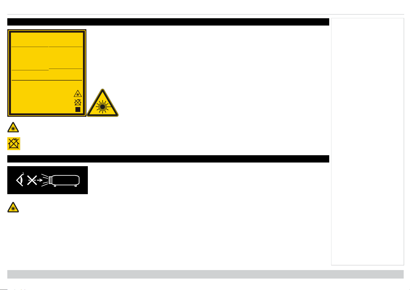
Laser information Digital Projection Ltd. M-Vision Laser 21K Series
326XXXXXX
2D
Code
GB 7247.1-2012 / IEC/EN 60825-1:2007
CLASS 1 LASER PRODUCT
一类激光产品
IEC/EN 60825-1:2014
PRODUIT LASER DE CLASSE 1
第一類雷射產品
IEC/EN 60825-1:2014
Warning ! Do not look into the beam.
No direct eye exposure to the beam
is permitted.
RG3
Hazard Distance : 0-650 cm
Avertissement ! Ne Pas Regarder
Directement Dans Le Faisceau.
L’exposition Directe Des Yeux Au
Faisceau Est Interdite.
RG3
Distance À Risque :
0-650
cm
警告 !请勿直视镜头。
眼睛不要直接暴露于光辐射 。
RG3
危险距离:0-650厘米
警告 ! 請勿直視鏡頭。
眼睛不要直接暴露於光輻射。
RG3
危險距離:0-650公分
LASER RADIATION
AVOID DIRECT EYE EXPOSURE
CLASS 3R LASER PRODUCT
Emitted Wavelength : 450-460 nm (Blue)
max pulse energy : 0.45 mJ (Blue)
Pulse duration : 0.87 ms (Blue)
Emitted Wavelength : 636-640 nm (Red)
max pulse energy : 0.77 mJ (Red)
Pulse duration : 1.77 ms (Red)
RAYONNEMENT LASER
EXPOSITION DIRECTE DANGEREUSE
POUR LES YEUX
APPAREIL À LASER DE CLASSE 3R
longueur d'onde : 450-460 nm (Bleu)
maximum énergie de impulsion : 0.45 mJ (Bleu)
durée de impulsion : 0.87 ms (Bleu)
longueur d'onde : 636-640 nm (Rouge)
maximum énergie de impulsion : 0.77 mJ (Rouge)
durée de impulsion : 1.77 ms (Rouge)
激光辐射
避免眼睛受到直接照射
3R类激光产品 波长 : 450-460 nm (蓝)
最大脉冲能量: 0.45 mJ (蓝),
脉冲时间: 0.87 ms (蓝)
3R类激光产品 波长 : 636-640 nm (红)
最大脉冲能量: 0.77 mJ (红),
脉冲时间: 1.77 ms (红)
激光輻射
避免眼睛受到直接照射
3R類雷射產品 波長: 450-460 nm (藍)
最大脈衝能量: 0.45 mJ (藍),
脈衝時間: 0.87 ms (藍)
3R類雷射產品 波長: 636-640 nm (紅)
最大脈衝能量: 0.77 mJ (紅),
脈衝時間: 1.77 ms (紅)
Laser information
Caution - use of controls or adjustments or performance of procedures other than those specified herein may result in hazardous radiation
exposure.
Not for home use.
Optical radiation
Notes
Caution - possibly hazardous optical radiation emitted from this product. Do not stare at operating light source. May be harmful to eyes. This
projector is tested according to IEC/EN62471-5:2015 (Photobiological safety of lamps and lamp systems – Part 5: Image projectors standard) and is
Risk Group 3 (high risk).
Introduction
Rev A June 2019
page3
Page 4
Digital Projection Ltd. M-Vision Laser 21K Series Light Hazard Warning
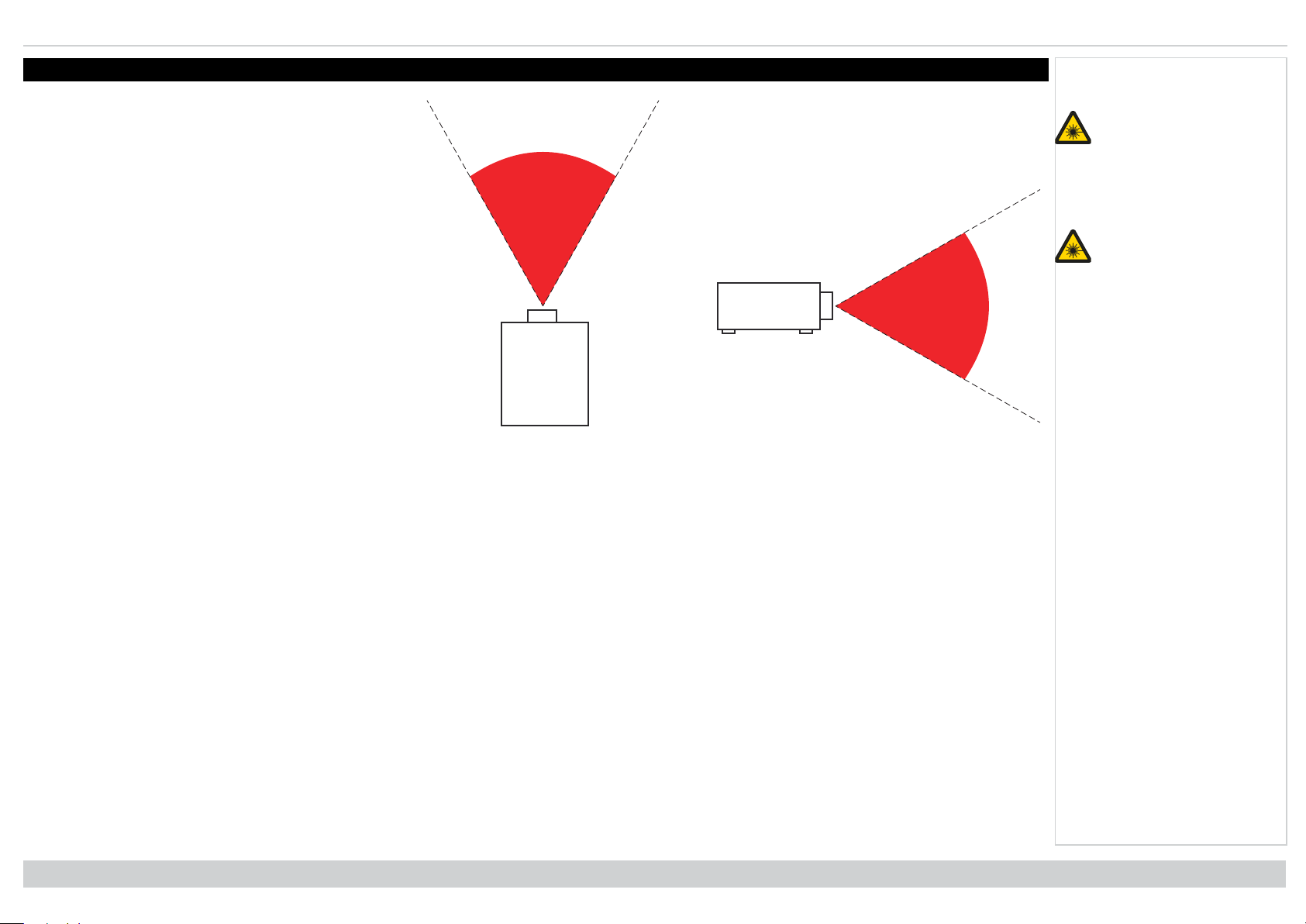
Light Hazard Warning
The hazard distance is the distance measured from the
projection lens at which the intensity or energy per unit of
surface is lower than the applicable exposure limit on the
cornea or skin. If the person is within the hazard distance, the
beam is considered unsafe for exposure.
Light Hazard Distances
The hazard distance for this projector is 6.5 m.
Notes
No direct exposure to the
beam is permitted, RG3
IEC 62471-5:2015.
Operators should control
access to the beam
within the hazard
distance or install the
projector at sufficient
height to prevent
exposures of spectators’
eyes within the hazard
distance.
Hazard Distance
Rev A June 2019
page4
Introduction
Page 5

Introduction Digital Projection Ltd. M-Vision Laser 21K Series
Introduction
Congratulations on your purchase of this Digital Projection product. Your projector has the following key features:
l WUXGA projector.
l WUXGA native resolution delivering 21,000 ISO lumens.
l Support for Frame Sequential and Dual Pipe 3D formats.
l HDBaseT® for transmission of uncompressed High Definition Video up to 100 m from the source.
l 3G-SDI with loop-through.
l Edge Blend with black level correction.
l Red laser assist for enhanced color fidelity.
l Blanking control for custom input window sizing.
l Cornerstone, Vertical & Horizontal Keystone, Pincushion & Barrel, and Image Rotation.
l Control via LAN and RS232.
l Motorised lens mount.
l Separate control of screen and source aspect ratio.
l Non-linear warp for irregular projection surfaces.
l Constant brightness mode maintains light output at selected levels.
A serial number is located on the side of the projector. Record it here:
Notes
Introduction
Rev A June 2019
page5
Page 6
Digital Projection Ltd. M-Vision Laser 21K Series Contents
Contents
About this document 2
Symbols used in this document 2
Product revision 2
Legal notice 2
Laser information 3
Optical radiation 3
Light Hazard Warning 4
Light Hazard Distances 4
Introduction 5
Contents 6
What's in the box? 10
Connecting the power supply 11
Projector overview 12
Control panel 13
Remote control 14
Notes
Switching the projector off 25
Selecting an input signal 25
Selecting a test pattern 25
Adjusting the lens 26
Lens menu 26
Remote control 26
Adjusting the image 26
Orientation 26
Geometry 26
Picture 26
Signal inputs 28
Digital inputs and outputs 28
EDID on the DisplayPort, HDMI, and HDbaseT inputs 29
Using DisplayPort/ HDMI/ HDBaseT switchers with the projector 29
3D connections 30
Infrared reception 17
Positioning the screen and projector 18
Roll and pitch 19
Stacking and rigging 20
Pin and cup stacking 20
Changing the lens 22
Inserting a new lens 22
Removing the lens 23
Fitting a lens hood 24
Operating the projector 25
Switching the projector on 25
Rev A June 2019
page6
Frame sequential 1080p 3D up to 120Hz and WUXGA 3D at 100Hz 30
Dual Pipe 1080p, WUXGA and WQXGA+ 3D sources at up to 100 and
120Hz 30
3D Sync 31
Control connections 32
LAN connection examples 33
RS232 connection example 34
Using the menus 36
Opening the Menu 36
Opening a submenu 36
Exiting menus and closing the OSD 37
Introduction
Page 7
Contents Digital Projection Ltd. M-Vision Laser 21K Series
Inside a menu 37
Accessing sub menus 38
Executing commands 38
Editing projector settings 39
Using a slider to set a value 39
Editing numeric values 40
Using the projector 41
Main menu 41
Lens menu 42
Lens control 42
Lens memory 43
Image menu 44
Color menu 45
Color space 45
Color mode 46
ColorMax 46
Manual color matching 47
Blanking 56
Keystone 57
Keystone example 58
Keystone settings 59
4 corners 60
Top right corner example 61
Rotation 62
Rotation example 63
Pincushion / barrel 64
Pincushion/ Barrel example 64
Arc 65
Custom warp 66
Warping grids 67
Custom masking 67
Edge blend menu 68
Blend start 69
Blend width 70
Notes
Color matching parameters explained 48
Color temperature 49
Gains and lifts 49
3 Color Matching 50
7 Color Matching 51
Geometry menu 52
Aspect ratio 52
Theaterscope setting 53
Digital zoom 54
Overscan 55
Introduction
Black level uplift 71
3D menu 72
3D types 73
Some 3D settings explained 74
Dark time 74
Eye swap 74
Sync offset 75
Laser menu 76
Setup menu 77
ColorMax 79
Rev A June 2019
page7
Page 8
Digital Projection Ltd. M-Vision Laser 21K Series Contents
Measured data/ target data 79
Power on / off 80
Clock adjust 81
OSDsettings 81
Memory 82
EDID Mode 82
Network menu 83
PIP menu 84
Information menu 85
Signal format 85
System status 86
Thermal status 86
Factory reset 87
Served web pages 88
Choosing a lens 90
Basic calculation 91
Basic calculation example 92
WUXGA images displayed full height 97
Diagonal screen sizes 97
Positioning the image 98
Aspect ratios explained 100
Aspect ratios examples 100
Source: 4:3 100
Source: 16:9 101
Source: 16:10 (native) 101
Aspect ratio example: TheatreScope 102
Appendix A: supported signal input modes 103
2D formats 103
3D formats 105
Appendix B: wiring details 107
Signal inputs and outputs 107
HDMI 1 and 2 107
DisplayPort 108
3G-SDI in, 3G-SDI out 109
Notes
Full lens calculation 93
Introducing TRC 93
Calculating TRC 94
TRC table 94
Calculating the throw ratio with TRC 94
Full lens calculation example 95
Screen requirements 96
Fitting the image to the display 96
WUXGA images displayed full width 96
WUXGA images displayed with a height of 1200 pixels 96
Rev A June 2019
page8
HDBaseT input 109
Control connections 110
LAN 110
RS232 110
IR input 110
Appendix C: glossary of terms 111
Introduction
Page 9
M-Vision Laser21K Series
High Brightness Digital Video Projector
INSTALLATION & QUICK START GUIDE
Rev A June 2019
119-680
Page 10
Digital Projection Ltd. M-Vision Laser 21K Series What's in the box?
PicMute
OPEN
CLOSE
MENU
EXIT INFO
HDMI1
OK
OFF ON
ALT
LENS
FOCUS ZOOM
IN
OUT
IN
OUT
SHIFT
21 3
HDMI2 DVI
DisplayPort1
HD-T 3GSDI
VGA COMP1 COMP2
HDMI3
TEST
HDMI4
DisplayPort2
R G B ALL
3D EYE PIP SWAP
4 5 6
7 8 9 0
ALT
ADDR
OSD
OFF
ON
DEFAULT
FREEZE
RE-SYNC
A B C D
USERPRESET
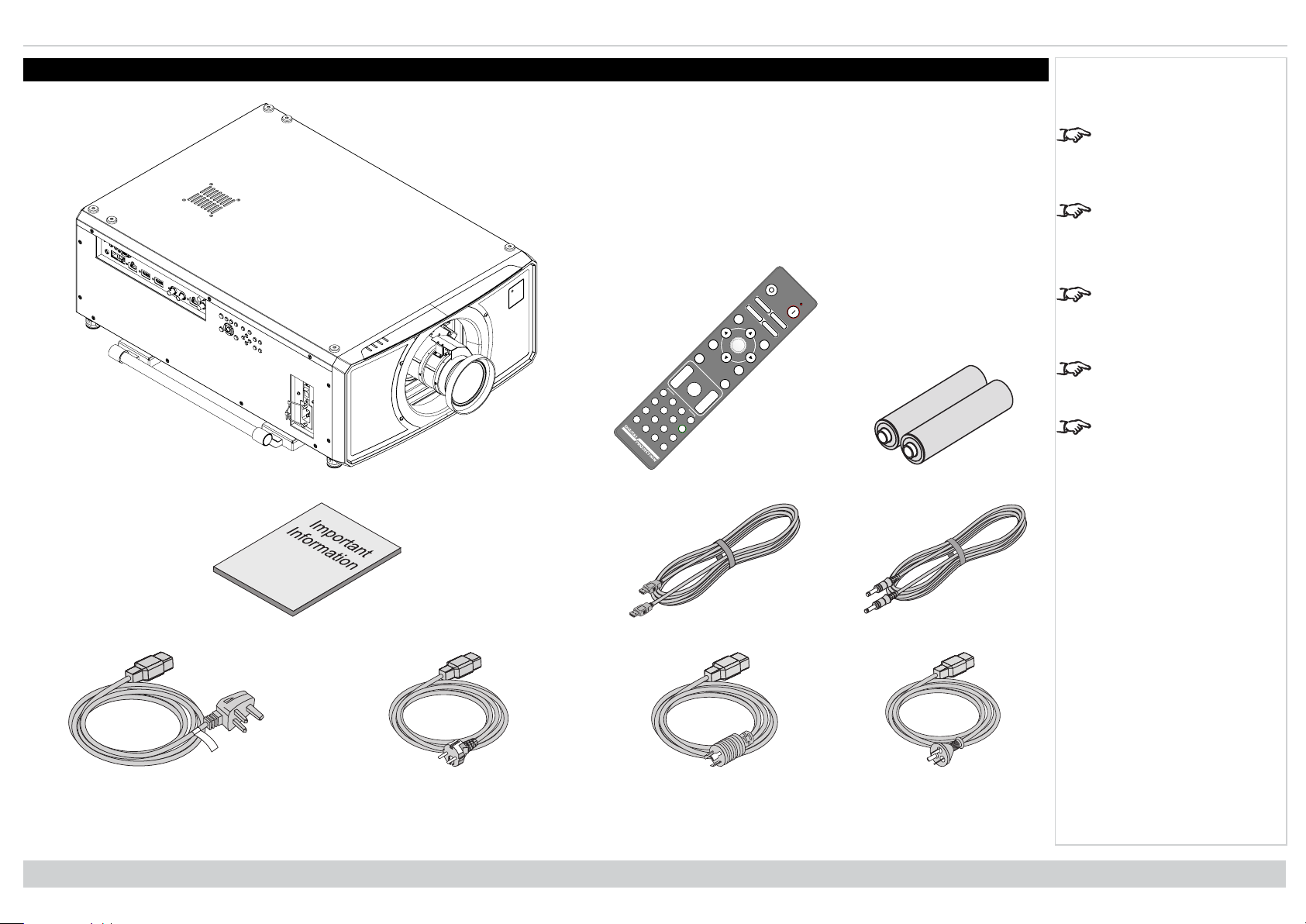
What's in the box?
Projector
Notes
Make sure your box
contains everything listed.
If any pieces are missing,
contact your dealer.
Only one remote is
supplied with the
projector.
Save and store the
original box and packing
materials, in case you
ever need to ship your
projector.
The projector is shipped
without a lens.
Only the appropriate cable
for destination territory is
supplied with the projector
Remote Control Batteries
Rev A June 2019
page10
Important Information Book HDMI Cable Remote Control Cable
Power Cable, UK Power Cable, Europe Power Cable, North America Power Cable, China
Installation & Quick Start Guide
Page 11
Connectingthe powersupply Digital Projection Ltd. M-Vision Laser 21K Series
1
1
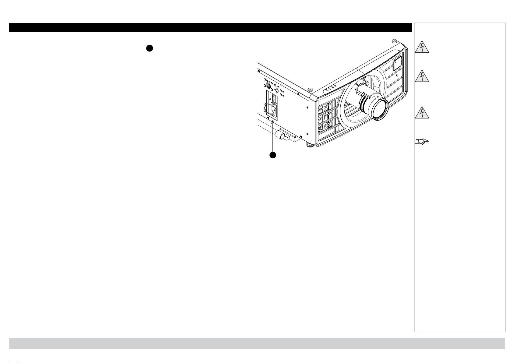
Connecting the power supply
1. Lift the cable lock up
2.
Firmly push the mains connector into the socket
3. Push the lock down to secure the cable
Notes
Use only the power cable
provided.
Ensure that the power
outlet includes a ground
connection as this
equipment MUST be
earthed.
Handle the power cable
carefully and avoid sharp
bends. Do not use a
damaged power cable.
Light output power is
reduced by approx 35%
when operating on 110V.
Installation & Quick Start Guide
Rev A June 2019
page11
Page 12
Digital Projection Ltd. M-Vision Laser 21K Series Projector overview
123
4
5
6
7
8
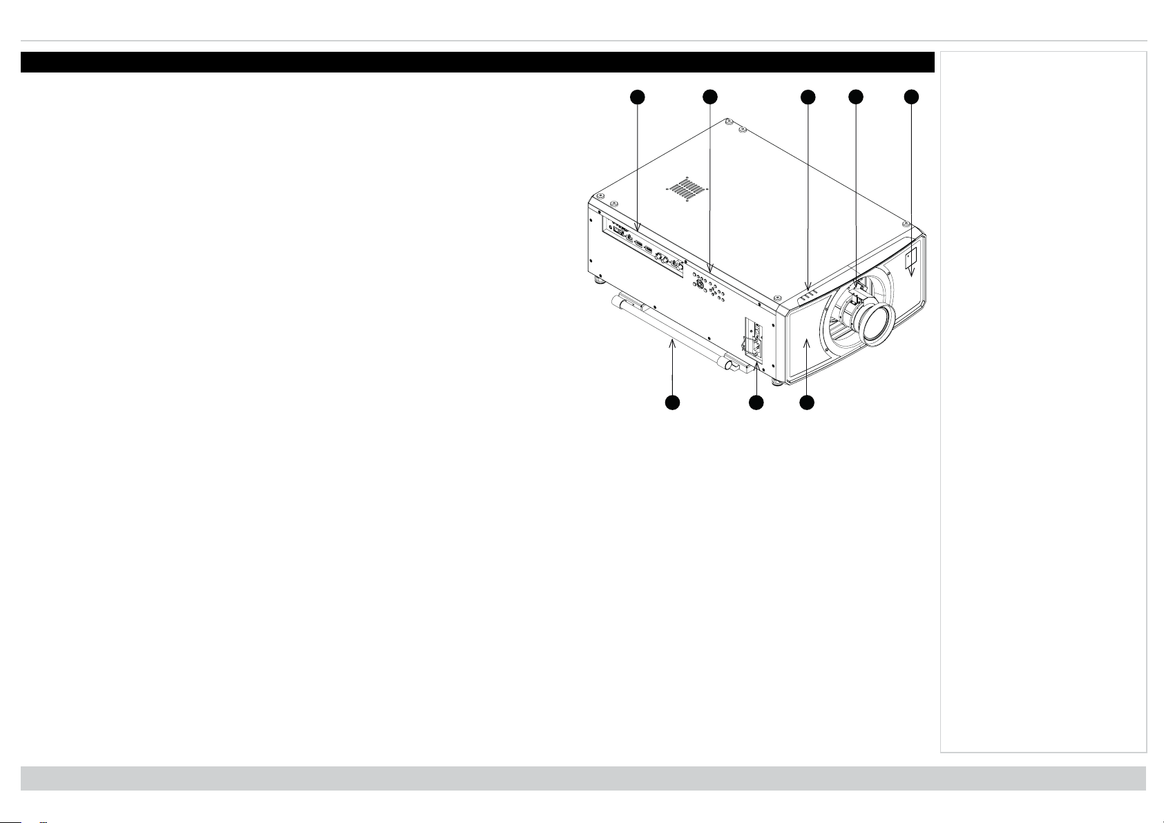
Projector overview
1. Connections panel
2. Control panel
3. Indicators
4. Lens mount
5. Front infrared window
6. Lifting handles
7. Mains socket and switch
8. Air inlet
Notes
Front View
Rev A June 2019
page12
Installation & Quick Start Guide
Page 13

Controlpanel Digital Projection Ltd. M-Vision Laser 21K Series
POWER
INPUT
AUTO
SYNC
ASPECT
CENTER
LENS
PIC MUTE
12345
6
7 8 9 10 11 12
Control panel
1. POWER
Switches the projector on and off (STANDBY).
2. INPUT
Switches to the next input source.
3. AUTO SYNC
Re-synchronises with the current input signal.
4. ASPECT
Changes the aspect ratio.
5. CENTER LENS
Centers the lens.
6. PIC MUTE Shows and hides the projected image. When
muted, the light source is completely switched off and
the screen is black.
7. MENU
Displays and exits the OSD.
8. Arrow buttons & ENTER
Navigation buttons used to highlight menu entries in the
OSD. Press ENTER to open or execute the highlighted
menu entry.
9. EXIT
Exits the current OSD page and enters the level above.
10. LENS SHIFT
Arrow buttons move the lens in the specified direction.
11. FOCUS
Plus and minus buttons move the focus in and out.
12. ZOOM
Plus and minus buttons zoom in and out.
Notes
Control Panel
Installation & Quick Start Guide
Rev A June 2019
page13
Page 14
Digital Projection Ltd. M-Vision Laser 21K Series Remote control
Pic Mute
OPEN
CLOSE
MENU
EXIT INFO
HDMI1
OK
OFF ON
ALT
LENS
FOCUS ZOOM
IN
OUT
IN
OUT
SHIFT
21 3
HDMI2 DVI
DisplayPort1
HD-T 3GSDI
VGA COMP1 COMP2
HDMI3
TEST
HDMI4
DisplayPort2
R G B ALL
3D EYE PIP SWAP
4 5 6
7 8 9 0
ALT
ADDR
OSD
OFF
ON
DEFAULT
FREEZE
RE-SYNC
A B C D
USER PRESET
8
6
543
217
9
10
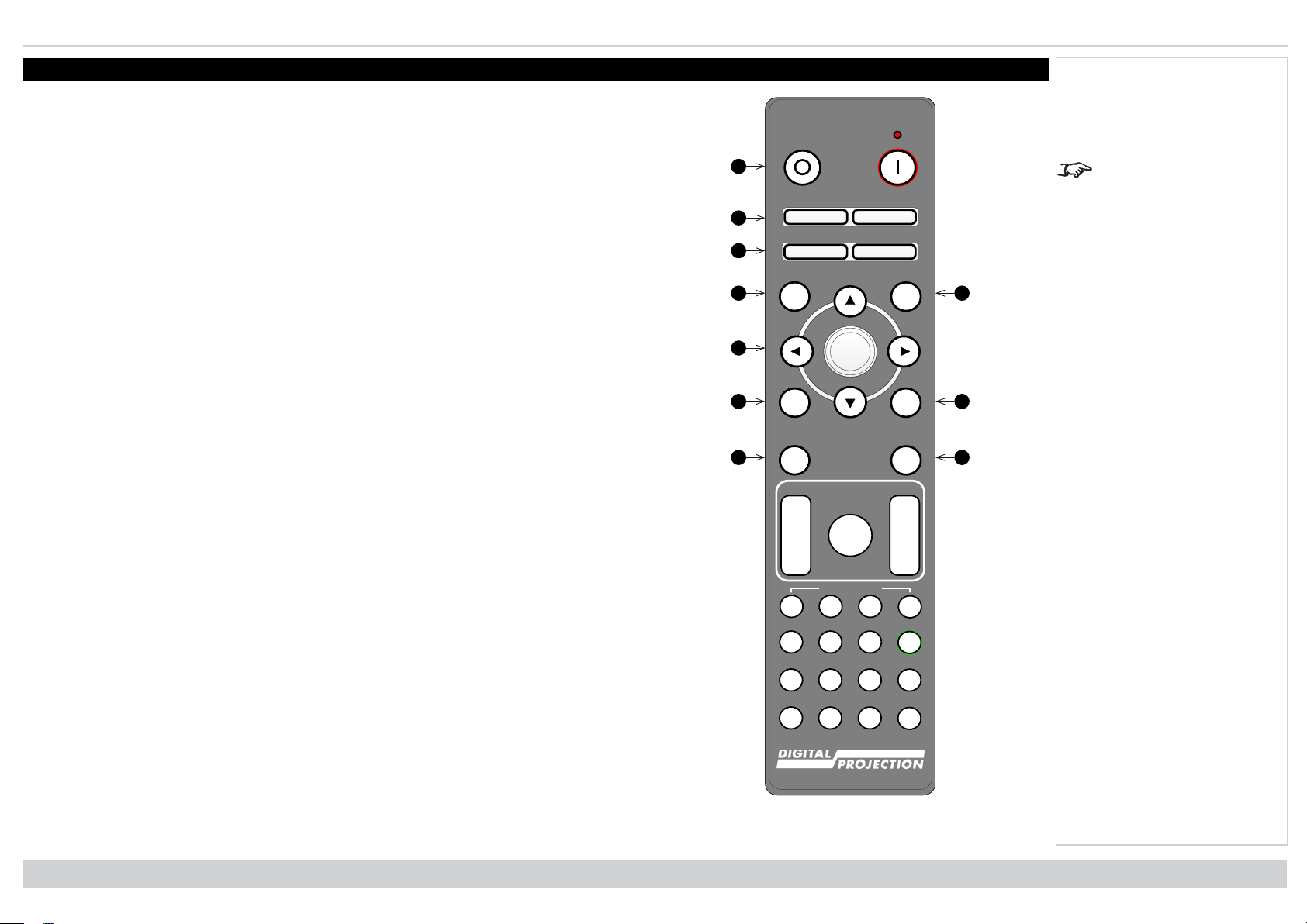
Remote control
1. Power ON / OFF
Turns power on and off.
2. Pic Mute OPEN / CLOSE
Shows and hides the projected image.
There are two PIC Mute settings:
l Laser. When off, the laser is switched off and no image is projected
l DMD Blanking. When off, the laser remains on and a black image is projected
3. OSD ON / OFF
Enable and disable screen timeout messages and control whether to show the OSD during
projection.
4. MENU
Access the OSD. If the OSD is open, press this button to go back to the previous menu.
5. Navigation (arrows and OK)
6. EXIT
7. FREEZE
8. DEFAULT
9. INFO
10. RE-SYNC
Navigate through the menus with the arrows, confirm your choice with OK.
In lens adjustment modes, the arrows are used to move, zoom or focus the lens.
See 11 below. In lens adjustment modes, or when the OSD is not showing, the OK button
switches between modes: Shift Adjustment and Zoom / Focus Adjustment.
Go up one level in the OSD. When the top level is reached, press to close the OSD.
Freeze the current frame.
When editing a parameter, press this button to restore the default value.
Access information about the projector.
Re-synchronise with the current input signal
Notes
The PIC Mute setting is
defined in the setup menu.
See Setup menu on
page77
Rev A June 2019
page14
Remote Control
Installation & Quick Start Guide
Page 15
Remotecontrol Digital Projection Ltd. M-Vision Laser 21K Series
Pic Mute
OPEN
CLOSE
MENU
EXIT INFO
HDMI1
OK
OFF ON
ALT
LENS
FOCUS ZOOM
IN
OUT
IN
OUT
SHIFT
21 3
HDMI2 DVI
DisplayPort1
HD-T 3GSDI
VGA COMP1 COMP2
HDMI3
TEST
HDMI4
DisplayPort2
R G B ALL
3D EYE PIP SWAP
4 5 6
7 8 9 0
ALT
ADDR
OSD
OFF
ON
DEFAULT
FREEZE
RE-SYNC
A B C D
USER PRESET
11
13
12
14
15
16
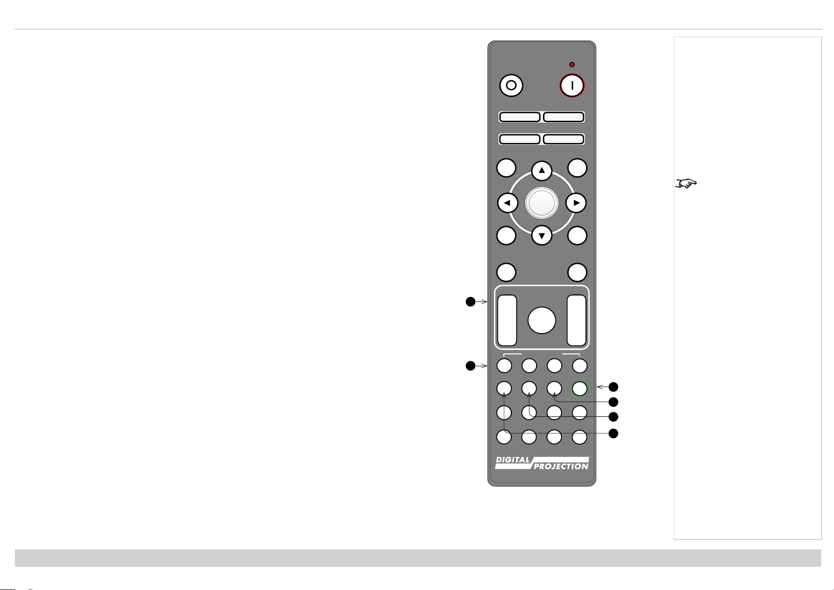
11. LENS adjustment
l FOCUS IN / OUT: adjust focus.
l SHIFT: press and hold this button, then use the Navigation arrow buttons to move the
lens.
l ZOOM IN / OUT: adjust zoom.
12. USER PRESET A, B, C, D
Load user presets.
13. ALT
Press and hold this button to access alternative functions for all buttons with a green label.
14. DVI / DisplayPort2 / numeric input 3
There is no DVI input on this projector.
Use with ALT to select the DisplayPort 2 input.
15. HDMI 2 / HDMI 4 / numeric input 2
16. HDMI 1 / HDMI 3 / numeric input 1
Select the HDMI 2 input.
There is no HDMI 4 input on this projector
Select the HDMI 1 input.
There is no HDMI input on this projector
Notes
This projector does not
use the following options
on the remote: DVI, VGA,
COMP 1 and COMP 2.
Installation & Quick Start Guide
Remote Control
Rev A June 2019
page15
Page 16
Digital Projection Ltd. M-Vision Laser 21K Series Remote control
Pic Mute
OPEN
CLOSE
MENU
EXIT INFO
HDMI1
OK
OFF ON
ALT
LENS
FOCUS ZOOM
IN
OUT
IN
OUT
SHIFT
21 3
HDMI2 DVI
DisplayPort1
HD-T 3GSDI
VGA COMP1 COMP2
HDMI3
TEST
HDMI4
DisplayPort2
R G B ALL
3D EYE PIP SWAP
4 5 6
7 8 9 0
ALT
ADDR
OSD
OFF
ON
DEFAULT
FREEZE
RE-SYNC
A B C D
USER PRESET
17
23
19
21
222418
20
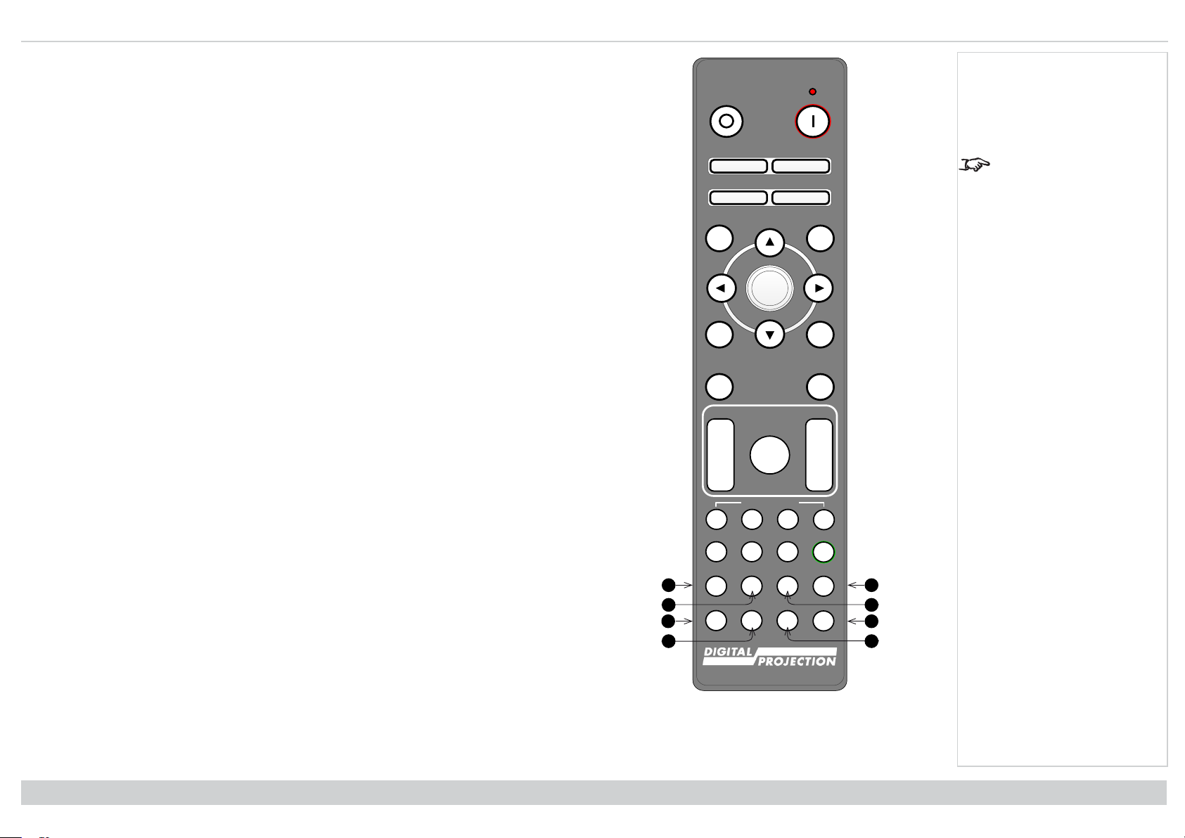
17. DISPLAYPORT 1 / R / numeric input 4
Select DisplayPort 1 input.
18. HD-T / G / numeric input 5
Select the HDBaseT input.
19. VGA / 3D / numeric input 7
There is no VGA input on this projector.
Use with ALT to toggle the 3D Format setting between Off and Auto.
20. COMP1 / EYE / numeric input 8
There is no Component 1 input on this projector.
Use with ALT to switch between left and right eye 3D dominance.
21. ADDR / ALL (with red indicator at the top)
Assign and unassign an IR remote address.
l To assign an IR remote address:
1. Press and hold this button until the red indicator starts flashing.
2. Release this button and while the red indicator is still flashing, enter a two-
l To unassign an address and return to the default address 00:
digit address using the numeric input buttons. The indicator will flash three
times quickly to confirm the change.
1. Press and hold ALT and this button simultaneously until the red indicator
flashes to confirm the change.
22. 3GSDI / B / numeric input 6
Select the 3G-SDI input.
23. TEST / SWAP / numeric input 0
Show a test pattern. Press again to show the next test pattern: White, Black, Red, Green,
Blue, Checkerboard, Crosshatch, V Burst, H Burst, Color Bar, Off..
When PIP mode is on, use this button with ALT to swap the main and sub images.
24. COMP2 / PIP / numeric input 9
There is no Component 2 input on this projector.
Use with ALT to switch on Picture In Picture (PIP) mode.
Notes
This projector does not
use the following options
on the remote: DVI, VGA,
COMP 1 and COMP 2.
Rev A June 2019
page16
Remote Control
Installation & Quick Start Guide
Page 17
Remotecontrol Digital Projection Ltd. M-Vision Laser 21K Series
40˚
40˚
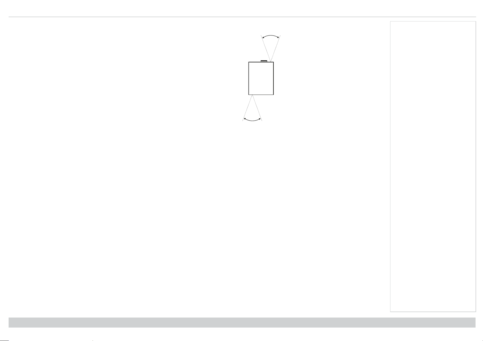
Infrared reception
The projector has infrared sensors at the front and back.
The angle of acceptance is 40°. Make sure that the remote control is within the angle of acceptance
when trying to control the projector.
Notes
Installation & Quick Start Guide
Rev A June 2019
page17
Page 18
Digital Projection Ltd. M-Vision Laser 21K Series Positioningthe screen and projector
121
2
221
1
2
2
Positioning the screen and projector
1. Install the screen, ensuring that it is in the best position for viewing by your audience.
2. Mount the projector, ensuring that it is at a suitable distance from the screen for the image to
fill the screen. Set the adjustable feet so that the projector is level, and perpendicular to the
screen.
The drawing shows the positions of the feet for table mounting, and the fixing holes for ceiling
mounting.
1. Four adjustable feet
2. Six M4 holes for ceiling mount The screws should not penetrate more than 15 mm into the
body of the projector.
Notes
Always allow the
projector to cool for 5
minutes before
disconnecting the power
or moving the projector.
Ensure that there is at
least 50 cm (19.7 in) of
space between the
ventilation outlets and
any wall, and 30 cm (11.8
in) on all other sides.
Do not use the threaded
holes for the adjustable
feet to hang or mount the
projector.
Rev A June 2019
page18
Installation & Quick Start Guide
Page 19
Positioningthe screen and projector Digital Projection Ltd. M-Vision Laser 21K Series
360˚
360˚
Roll and pitch
The projector can be operated in numerous positions.
Notes
Positioning the projector
with the lens facing down
or the inputs facing up
may reduce motor life.
Installation & Quick Start Guide
Roll
Pitch
Rev A June 2019
page19
Page 20
Digital Projection Ltd. M-Vision Laser 21K Series Positioningthe screen and projector
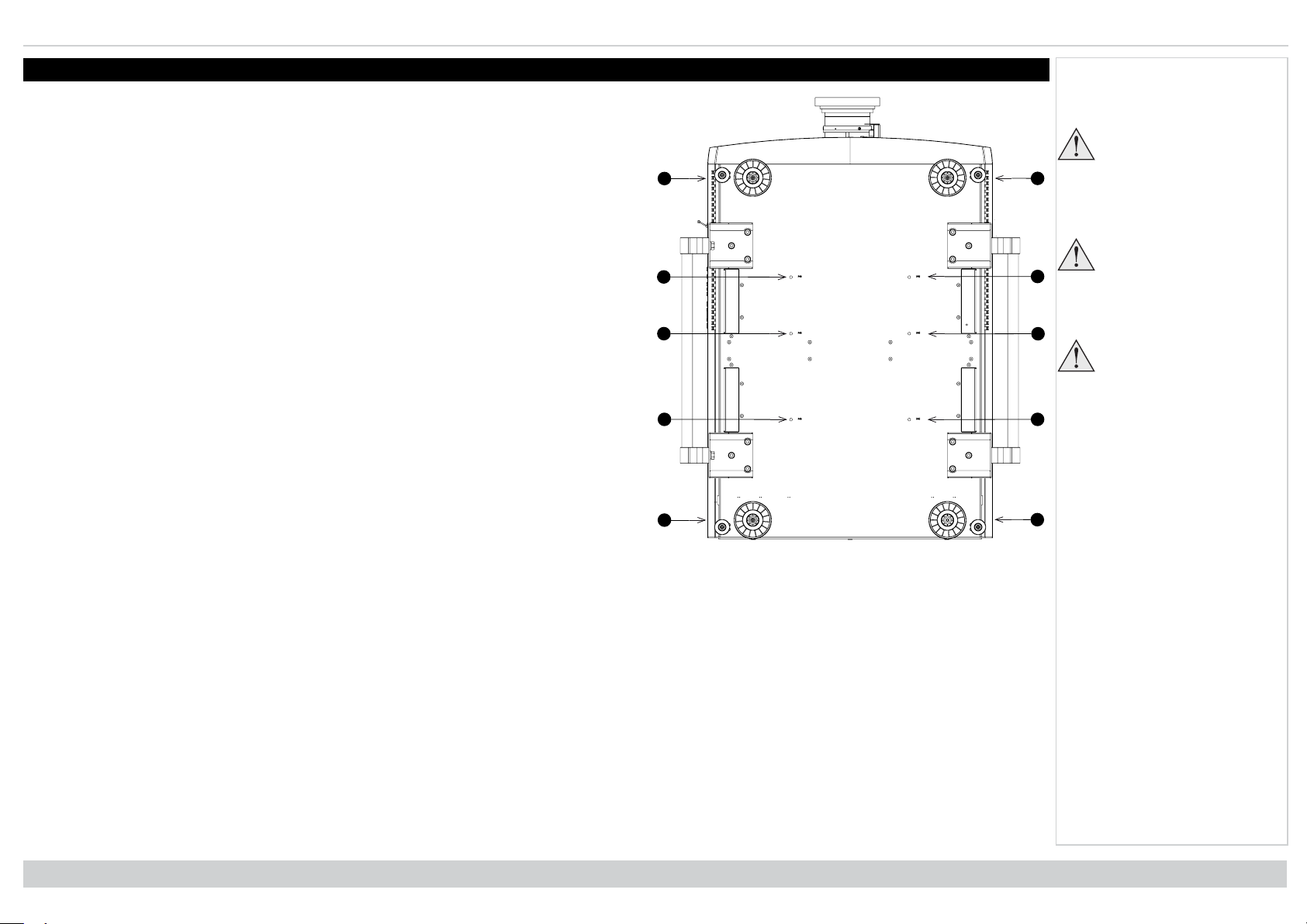
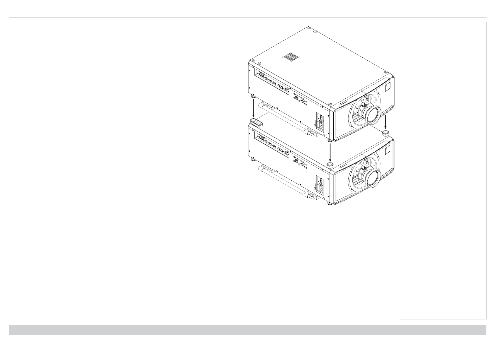
Stacking and rigging
Pin and cup stacking
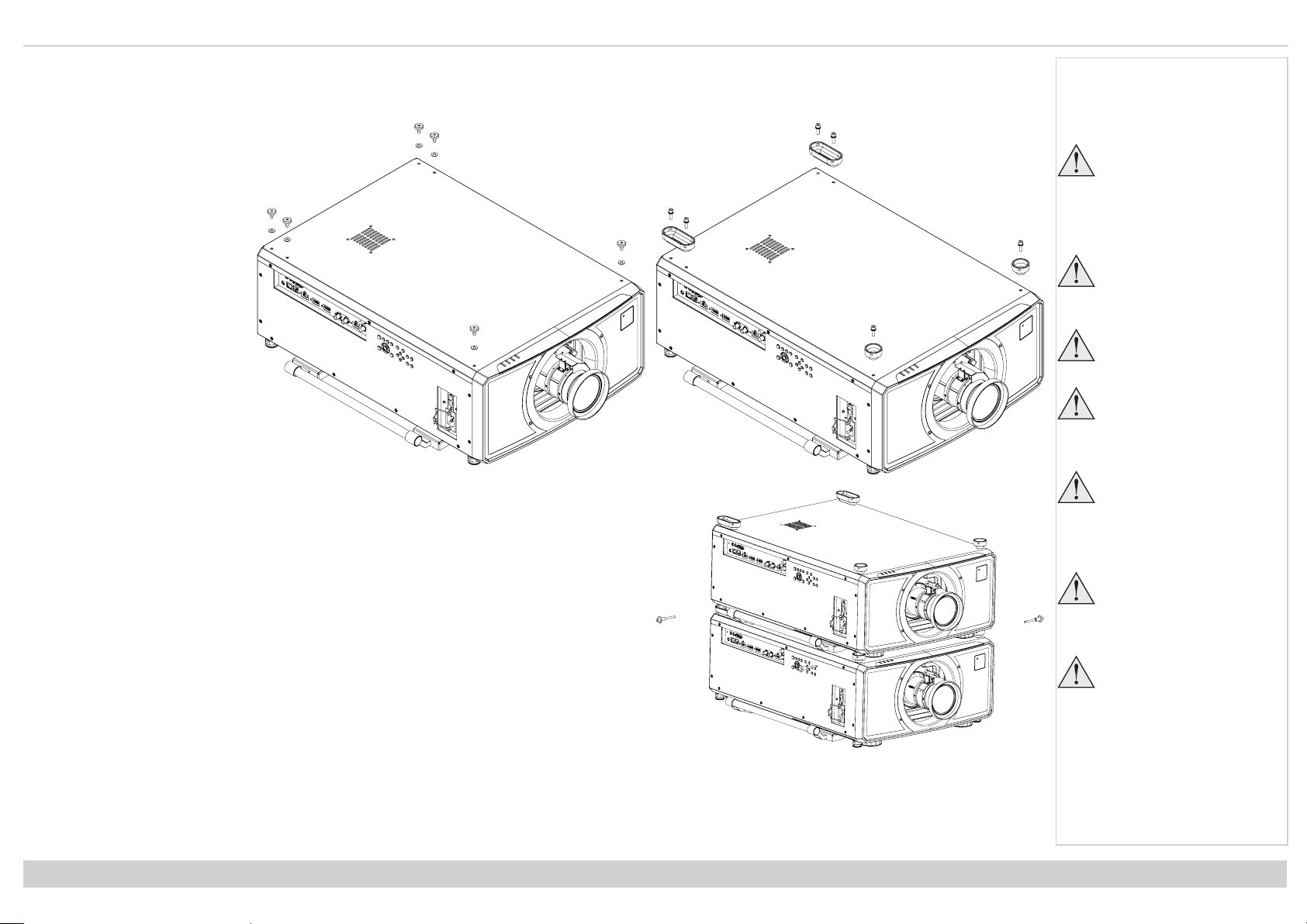
1. Remove the six screws on
the top side of the projector
that will be on the bottom of
the stack.
2. Insert and secure the
stacking tops in place of the
removed screws.
Notes
The projectors must be
in a vertical position
when they are stacked.
This will ensure that the
stresses are distributed
to all four corners of the
chassis.
Do not use the threaded
holes for the adjustable
feet to hang or mount the
projector.
Do not use the carry
handles to hang or mount
the projector.
Do not stack more than
two projectors.
Do not use the provided
eye bolts to suspend
stacked projectors. The
eye bolts can only carry
the weight of one
projector.
Rev A June 2019
page20
Use only the provided
screws with a torque of
25-30 kgf cm (2.45 - 2.94
Nm).
It is the customer’s
responsibility to ensure
that the assembly is
carried out securely.
Installation & Quick Start Guide
Page 21
Positioningthe screen and projector Digital Projection Ltd. M-Vision Laser 21K Series
3. Remove the adjustable feet from the projector that will be stacked on the top.
4. Mount the projector on top of the other projector. Ensure that all four cups are placed over
the pins on the bottom projector.
5. Use the provided holding pins to secure each connection.
Notes
Installation & Quick Start Guide
Rev A June 2019
page21
Page 22
Digital Projection Ltd. M-Vision Laser 21K Series Changingthe lens
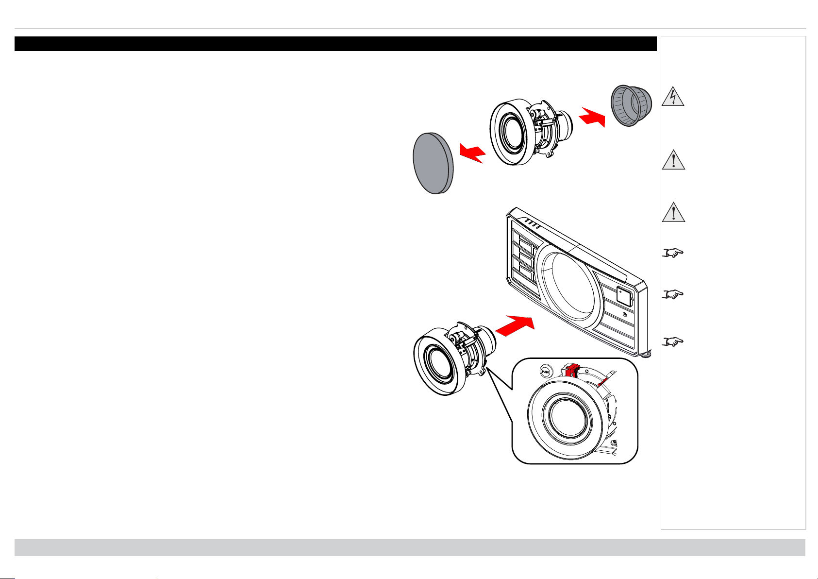
Changing the lens
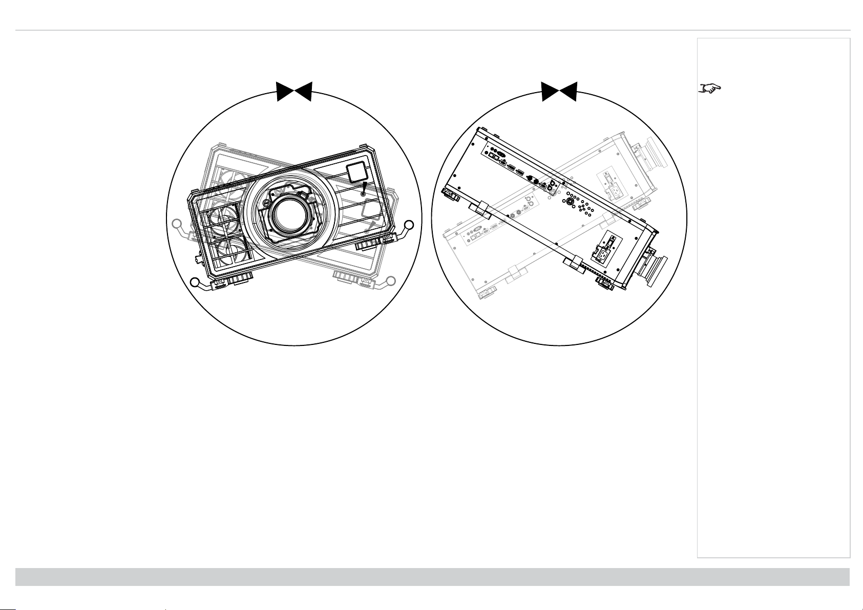
Inserting a new lens
1. Remove the front and rear lens caps
2. Insert the lens with the connector in upright position.
Notes
Before changing the
lens, always make sure
the projector is switched
off and fully
disconnected from its
power supply.
When changing the lens,
avoid using excessive
force as this may
damage the equipment.
Avoid touching the
surface of the lens as
this may result in image
impairment.
The lens is shipped
separately.
Take care to preserve the
original lens packaging
and protective caps for
future use.
Rev A June 2019
page22
The projector will not
power on without the lens
fitted.
Installation & Quick Start Guide
Page 23
Changingthe lens Digital Projection Ltd. M-Vision Laser 21K Series
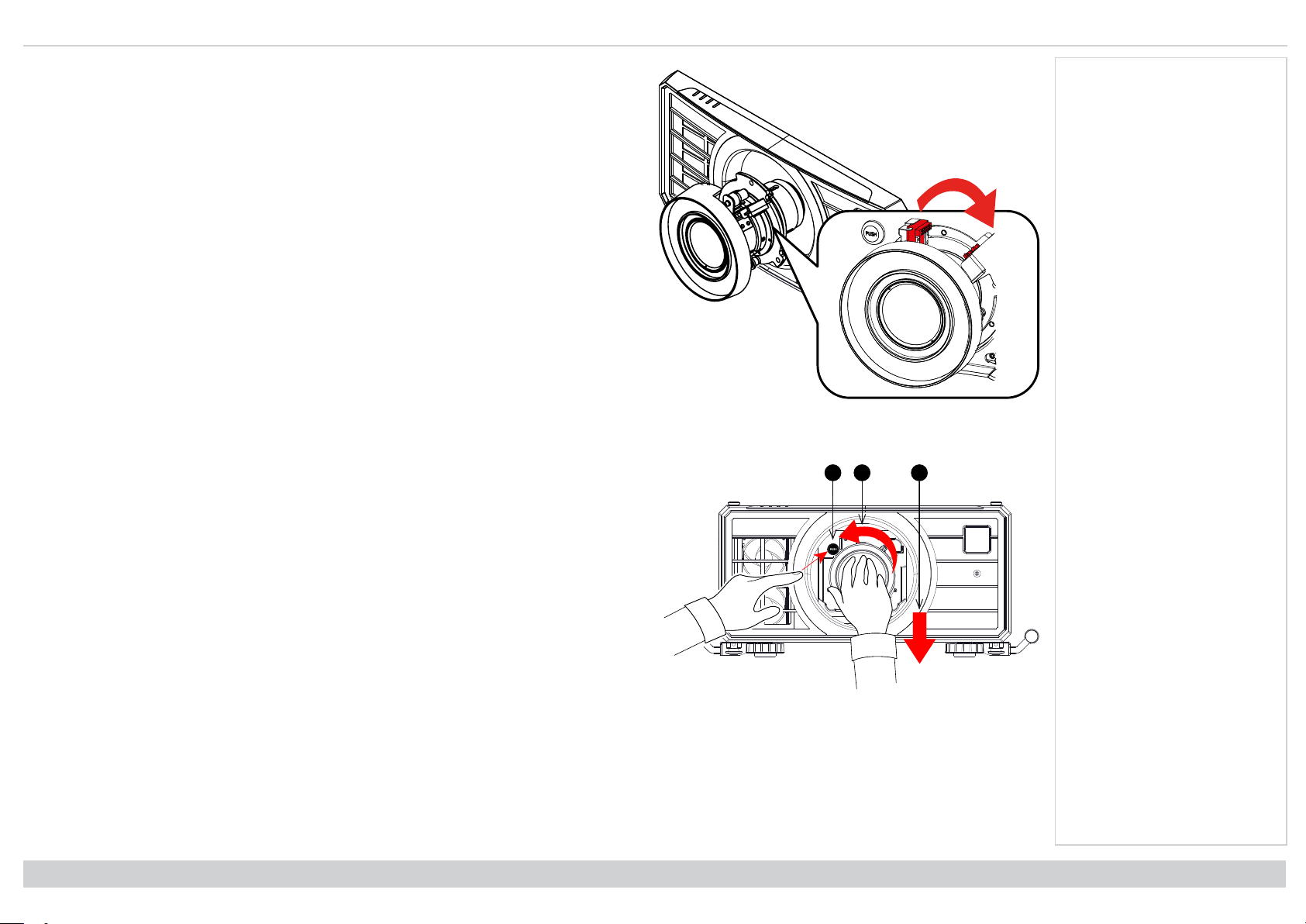
123
3. Rotate the lens clockwise until it clicks into place.
Removing the lens
1. Push the lens release button all the way in
2. Turn the lens anti-clockwise until it disengages
3. Slowly remove the lens.
Notes
Installation & Quick Start Guide
Rev A June 2019
page23
Page 24
Digital Projection Ltd. M-Vision Laser 21K Series Changingthe lens
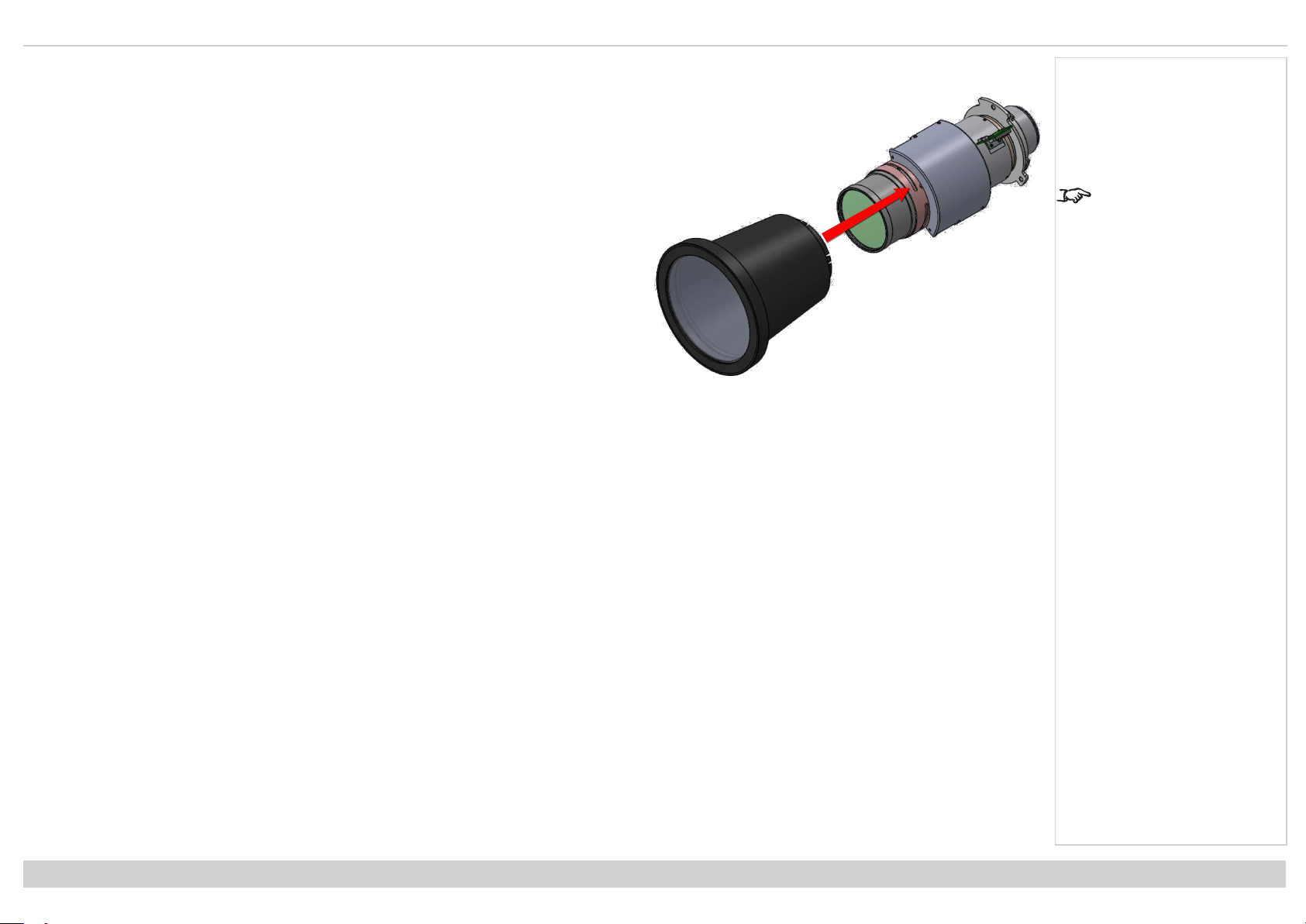
Fitting a lens hood
1. Push-fit the lens hood onto the lens.
Notes
FDA regulations requires
that a lens hood is
permanently fitted when
using the 4.00 - 7.00 : 1
zoom lens with the MVision Laser range of
projectors in the United
States of America. Fitting
can be provided by your
reseller or System
Integrator.
Rev A June 2019
page24
Installation & Quick Start Guide
Page 25
Operating the projector Digital Projection Ltd. M-Vision Laser 21K Series
Operating the projector
Switching the projector on
1. Ensure a lens is fitted. Connect the power cable between the mains supply and the projector. (See Connecting the power supply above.) Switch on at the
switch next to the power connector.
2. The POWER indicator lights red to signal that the projector is in STANDBY mode. Press one of the following buttons:
l On the remote control, the ON button
l On the projector control panel, the POWER button.
The fans begin working, then the POWER indicator begins flashing green. When the flashing stops, the POWER and LIGHT indicators both light steady green. The
projector is switched on.
Switching the projector off
1. Press OFF on the remote control or POWER on the control panel, then press again to confirm your choice.
The POWER indicator on the control panel will start flashing amber, the system will go out and the cooling fans will run for a short time until the POWER
indicator goes steady red to indicate that the projector has entered STANDBY mode.
2. If you need to switch the projector off completely, switch off at the mains power switch next to the power connector and then disconnect the power cable from
the projector.
Selecting an input signal
1. Connect one or more image sources to the projector.
2. Select the input you want to display:
l Press one of the input buttons on the remote control.
l Alternatively, open the On-screen display (OSD) by pressing MENU. Highlight Input from the main menu, press ENTER/OK and then select an input
signal using the UP and DOWN arrow buttons. Press ENTER/OK to confirm your choice.
Notes
See Connecting the
power supply on page11.
The self-test is running
when all the LEDs on the
control panel are lit.
Use only the power cable
provided.
Ensure that the power
outlet includes a ground
connection as this
equipment MUST be
earthed.
Handle the power cable
carefully and avoid sharp
bends. Do not use a
damaged power cable.
See Using the menus on
page36 for full details of
how to use the controls
and the menu system.
Selecting a test pattern
To display a test pattern:
l Press TEST on the remote control.
Change the test pattern using the LEFT and RIGHT arrow buttons. The following test patterns are available: White, Black, Red, Green, Blue, Checkerboard,
Crosshatch, V Burst, H Burst, Color Bar, Off.
l Alternatively, open the OSD by pressing MENU. Highlight Test Patterns from the main menu, then select a test pattern using the LEFT and RIGHT arrow
buttons.
After the final test pattern, the projector exits test pattern mode and returns to the main image. To view test patterns again, you need to press TEST again. If you wish
to exit the test patterns before you reach the final one, press TEST or EXIT at any time.
Installation & Quick Start Guide
Rev A June 2019
page25
Page 26

Digital Projection Ltd. M-Vision Laser 21K Series Operatingthe projector
Adjusting the lens
The lens can be adjusted using the Lens menu, or using the lens buttons on the remote control.
Lens menu
The Lens menu provides access to the Lens Control setting and the Lens Center command.
Lens Control allows Zoom, Focus and Shift adjustments using the arrow buttons. The setting operates in Zoom/Focus Adjustment and Shift Adjustment mode.
Press ENTER/SELECT to switch between the two modes.
Remote control
Use the remote control to adjust zoom, focus and shift directly, without opening a menu:
l OK enters lens control, then switches between Zoom/Focus Adjustment and Shift Adjustment.
l EXIT exits lens control and opens the Lens menu.
l MENU exits lens control and returns to the main image.
l The arrow buttons adjust zoom, focus and shift as indicated on the screen.
Adjusting the image
Orientation
This can be set from the Setup menu.
Highlight Orientation and choose from Front Tabletop, Front Ceiling, Rear Tabletop, Rear Ceiling and Auto-front.
Geometry
Notes
See Remote control on
page14 for full details of
how to adjust the lens
using the remote control.
Settings such as Keystone, Rotation, Pincushion / Barrel and Arc can be set from the Geometry menu.
Picture
Settings such as Gamma, Brightness, Contrast, Saturation, Hue and Sharpness can be set from the Image menu.
Rev A June 2019
page26
Installation & Quick Start Guide
Page 27

M-Vision Laser21K Series
High Brightness Digital Video Projector
CONNECTION GUIDE
Rev A June 2019
119-680
Page 28
Digital Projection Ltd. M-Vision Laser 21K Series Signal inputs
1
WIRED
REMOTE
RJ45
LAN
HDBaseT HDMI 1 DisplayPort 2DisplayPort 1 HDMI 2 3D SYNC - IN3G SDIIN3G SDI
OUT
3D SYNC - OUT
RS-2321 2TRIGGER
2
345
7
6
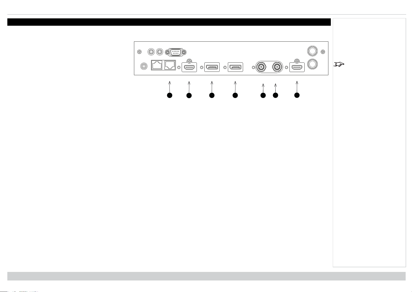
Signal inputs
Digital inputs and outputs
1. HDBaseT
Receives digital signal from HDBaseT-compliant
devices. Connect an HDBaseT cable.
2. HDMI 1
HDMI 1.4b input supporting Frame Sequential and
Dual Pipe 3D with HDCP 1.4. Also supports the
domestic Blu-Ray formats. See supported signal input
modes on page103. Connect an HDMI cable to the
connector.
3. DisplayPort 1
DisplayPort 1.1a input. Connect a DisplayPort cable to
the connector. Supports sources up to 1920 x 1200
resolution at 24 - 60 Hz. Supports HDCP.
4. DisplayPort 2
DisplayPort 1.1a input. Connect a DisplayPort cable to the connector. Supports sources up to 1920 x 1200 resolution at 24 - 60 Hz. Supports HDCP.
5. 3G-SDI in
6. 3G-SDI out
Connect a 3G-SDI cable to distribute the 3G-SDI signal to another projector.
7. HDMI 2
HDMI 1.4b input supporting Frame Sequential and Dual Pipe 3D with HDCP 1.4. Also supports the domestic Blu-Ray formats. See supported signal input
modes on page103. Connect an HDMI cable to the connector.
Notes
For simultaneous
HDBaseT and LAN
connectivity, a third-party
distribution product can be
utilised to combine
HDBaseT video stream
with LAN connection for
delivery to the projector.
Rev A June 2019
page28
Connection Guide
Page 29
Signal inputs Digital Projection Ltd. M-Vision Laser 21K Series
EDID
EDID
EDID
EDID
1 2 3
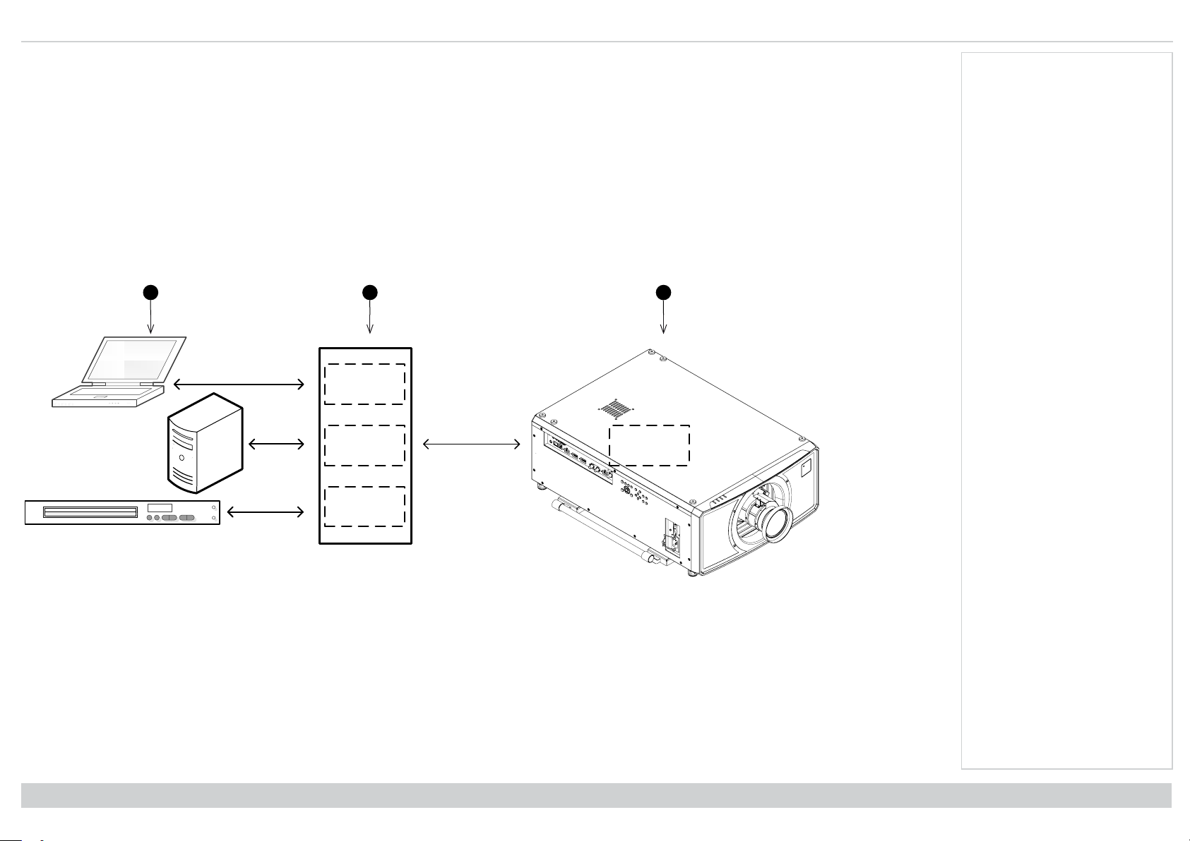
EDID on the DisplayPort, HDMI, and HDbaseT inputs
If you are using a computer graphics card or another source that obeys the EDID protocol, the source will automatically configure itself to suit the capability of the
projector.
Otherwise refer to the documentation supplied with the source to manually set the resolution to the DMD™ resolution of the projector or the nearest suitable setting.
Switch off the source, connect to the projector, then switch the source back on again.
Using DisplayPort/ HDMI/ HDBaseT switchers with the projector
When using a DisplayPort/HDMI/HDBaseT source switcher with the projector, it is important to set the switcher so that it passes the projector EDID through to the
source devices.
If this is not done, the projector may not be able to lock to the source or display the source correctly as its video output timings may not be compatible with those of
the projector. Sometimes this is called transparent, pass-through or clone mode. See your switcher’s manual for information on how to set this mode.
1. Sources
2. Switcher
3. Projector
Notes
Connection Guide
The EDIDs in the switcher should be the same as the one in the projector.
Rev A June 2019
page29
Page 30
Digital Projection Ltd. M-Vision Laser 21K Series 3D connections
WIRED
REMOTE
RJ45
LAN
HDBaseT HDMI 1 DisplayPort 2DisplayPort 1 HDMI 2 3D SYNC - IN3G SDIIN3G SDI
OUT
3D SYNC - OUT
RS-2321 2TRIGGER
1
2
3
4
5
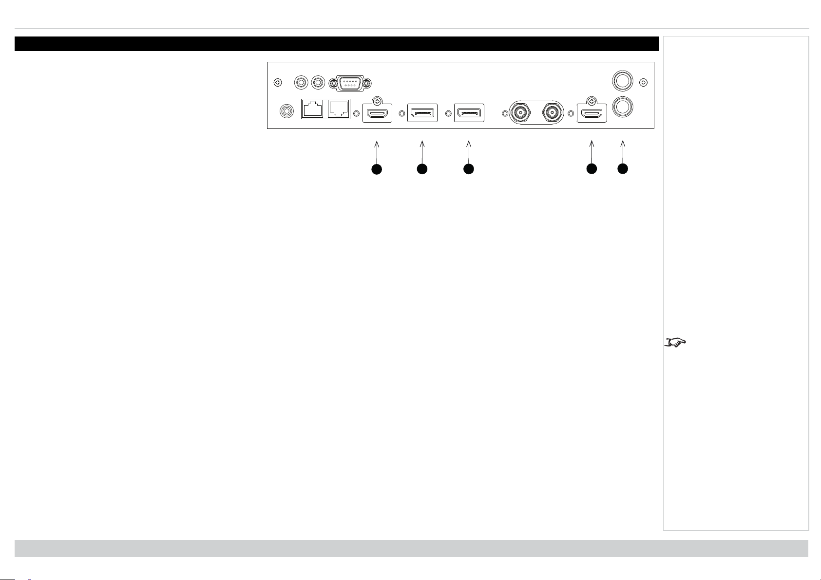
3D connections
1. HDMI 1 / Dual Pipe Left
HDMI 1.4b input supporting Frame Sequential and
Dual Pipe 3D with HDCP 1.4. Also supports the
domestic Blu-Ray formats. See supported signal input
modes on page103. Connect an HDMI cable to the
connector.
2. DisplayPort 1
DisplayPort 1.1a input supporting Frame Sequential
3D source up to 120Hz. Connect a DisplayPort cable
to the connector.
3. DisplayPort 2
DisplayPort 1.1a input supporting Frame Sequential
3D source up to 120Hz. Connect a DisplayPort cable to the connector.
4. HDMI 2 / Dual Pipe Right
HDMI 1.4b input supporting Frame Sequential and Dual Pipe 3D with HDCP 1.4. Also supports the domestic Blu-Ray formats. See supported signal input
modes on page103. Connect an HDMI cable to the connector.
5. Sync In / Sync Out
Sync In is the 3D sync input signal. Connect the 3D sync from your graphics card or server.
Sync Out is the 3D sync output signal. This is affected by settings in the 3D menu such as Dark Time and 3D Sync Offset. Connect this to an IR emitter or
ZScreen.
Frame sequential 1080p 3D up to 120Hz and WUXGA 3D at 100Hz
1. Connect to a DisplayPort input
2. Set 3D Format in the 3D menu to Frame Sequential.
Dual Pipe 1080p, WUXGA and WQXGA+ 3D sources at up to 100 and 120Hz
1. Connect the left eye output to the HDMI 1 socket and the right eye output to the HDMI 2 socket.
2. Set 3D Format in the 3D menu to Dual-Pipe.
Notes
See 3D formats on
page105 for a complete
list of supported formats
and frame rates.
Rev A June 2019
page30
Connection Guide
Page 31

3D connections Digital Projection Ltd. M-Vision Laser 21K Series
1
2
3
4
3D Sync
1. 3D Input
2. 3D Sync In
3. 3D Sync Out
4. IR emitter or Zscreen
Notes
Connection Guide
Rev A June 2019
page31
Page 32

Digital Projection Ltd. M-Vision Laser 21K Series Control connections
5
WIRED
REMOTE
RJ45
LAN
HDBaseT HDMI 1 DisplayPort 2DisplayPort 1 HDMI 2 3D SYNC - IN3G SDIIN3G SDI
OUT
3D SYNC - OUT
RS-2321 2TRIGGER
1
2
3
4
Control connections
1. Trigger 1 & Trigger 2
The Trigger outputs are defined in the Setup menu.
Each ouput can be triggered by one of the following
conditions:
l Screen trigger. A trigger output can be used to
control an electrically operated screen. The
screen will be automatically deployed when the
projector starts up and retracted when the
projector shuts down.
l Aspect ratio trigger. A trigger output can be
used to control screen shuttering for different
aspect ratios.
l RS232 trigger. A trigger output can be used to
control the screen or screen shuttering on
receipt of an RS232 command.
2. RS232
All of the projector’s features can be controlled via a serial connection, using commands described in the Protocol Guide.Use a straight-through cable to
connect directly to a computer.
3. Wired Remote
The remote control can be connected using a standard 3.5 mm mini jack cable (tip-ring-sleeve, or TRS).
4. HDBaseT/LAN
The projector’s features can be controlled via a LAN connection, using Digital Projection’s Projector Controller application or a terminal-emulation
program.
5. LAN
The projector’s features can be controlled via a LAN connection, using Digital Projection’s Projector Controller application or a terminal-emulation
program.
Notes
For a list of all commands
used to control the
projector via LAN, see the
Protocol Guide (available
separately).
Only one remote
connection (RS232 or
LAN) should be used at
any one time.
With a LAN connection the
projector can serve a web
page offering status and
projector controls.
Projector Controller is
available for download,
free of charge, from the
Digital Projection website.
Rev A June 2019
page32
Connection Guide
Page 33
Controlconnections Digital Projection Ltd. M-Vision Laser 21K Series
Un-crossed
LAN cable
Un-crossed LAN cables
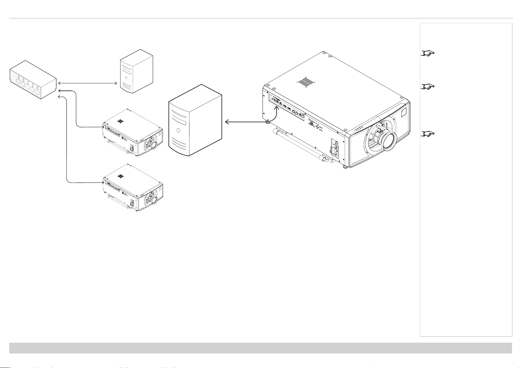
LAN connection examples
The projector’s features can be controlled via a LAN connection, using Digital Projection’s Projector Controller application or a terminal emulation program.
Notes
With a LAN connection the
projector can serve a web
page offering basic
projector controls.
Projector Controller is
available for download,
free of charge, from the
Digital Projection website.
For simultaneous
HDBaseT and LAN
connectivity, a third-party
distribution product can be
utilised to combine
HDBaseT video stream
with LAN connection for
delivery to the projector.
Connection Guide
Rev A June 2019
page33
Page 34
Digital Projection Ltd. M-Vision Laser 21K Series Control connections
Straight through cable
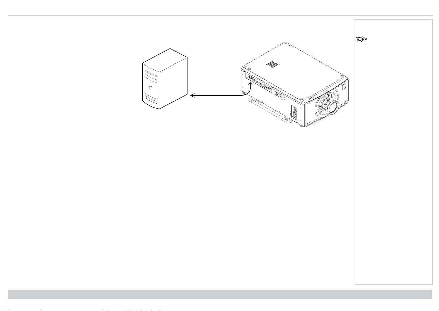
RS232 connection example
All of the projector’s features can be controlled via a serial connection, using commands described in the Protocol Guide.
Computer to Projector
Notes
The Protocol Guide is
available separately
Rev A June 2019
page34
Connection Guide
Page 35

M-Vision Laser21K Series
High Brightness Digital Video Projector
OPERATING GUIDE
Rev A June 2019
119-680
Page 36

Digital Projection Ltd. M-Vision Laser 21K Series Using the menus
Pic Mute
OPEN
CLOSE
MENU
EXIT INFO
HDMI1
OK
OFF ON
ALT
LENS
FOCUS ZOOM
IN
OUT
IN
OUT
SHIFT
21 3
HDMI2 DVI
DisplayPort1
HD-T 3GSDI
VGA COMP1 COMP2
HDMI3
TEST
HDMI4
DisplayPort2
R G B ALL
3D EYE PIP SWAP
4 5 6
7 8 9 0
ALT
ADDR
OSD
OFF
ON
DEFAULT
FREEZE
RE-SYNC
A B C D
USER PRESET
POWER
INPUT
AUTO
SYNC
ASPECT
CENTER
LENS
PIC MUTE
Using the menus
Opening the Menu
Access the various menus using
either the projector control panel or
the remote control. On either device:
1. Press the MENU button.
The on-screen display
(OSD) opens showing the
list of available menus
Notes
Projector control panel
Opening a submenu
Move up and down the list using the UP and DOWN arrow buttons.
To open a submenu:
1. Press ENTER on the control panel or OK on the remote control.
This guide refers to the above two buttons as ENTER/OK.
Rev A June 2019
page36
Remote control
Operating Guide
Page 37

Using the menus Digital Projection Ltd. M-Vision Laser 21K Series
Exiting menus and closing the OSD
To go back to the previous page:
1. Press EXIT.
To close the OSD:
1. Press MENU.
Or:
1. Go back to the top level menu
2. Press EXIT.
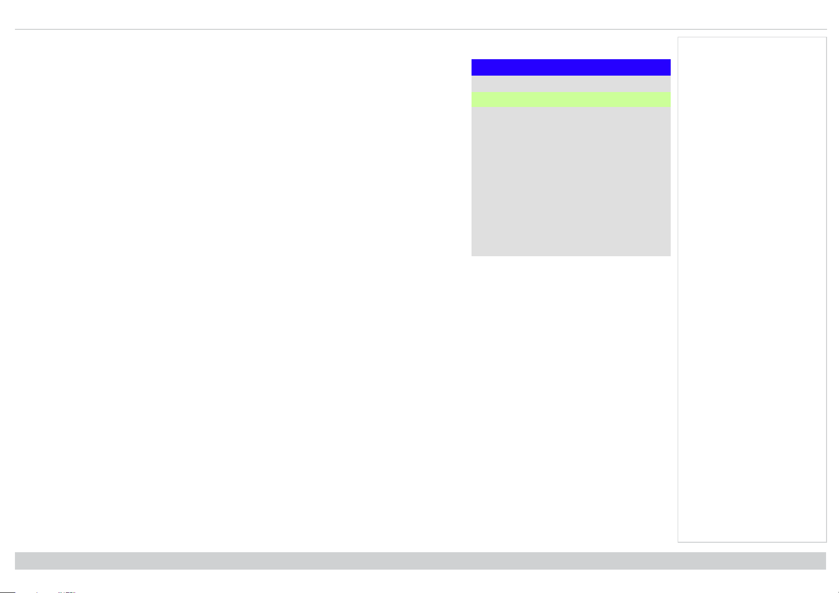
Input HDMI 1
Test Pattern
Lens ►
Image ►
Color ►
Geometry ►
Edge Blend ►
3D ►
Laser ►
Setup ►
Network ►
On Screen Display (OSD): Top Level Menu
Main Menu
▼
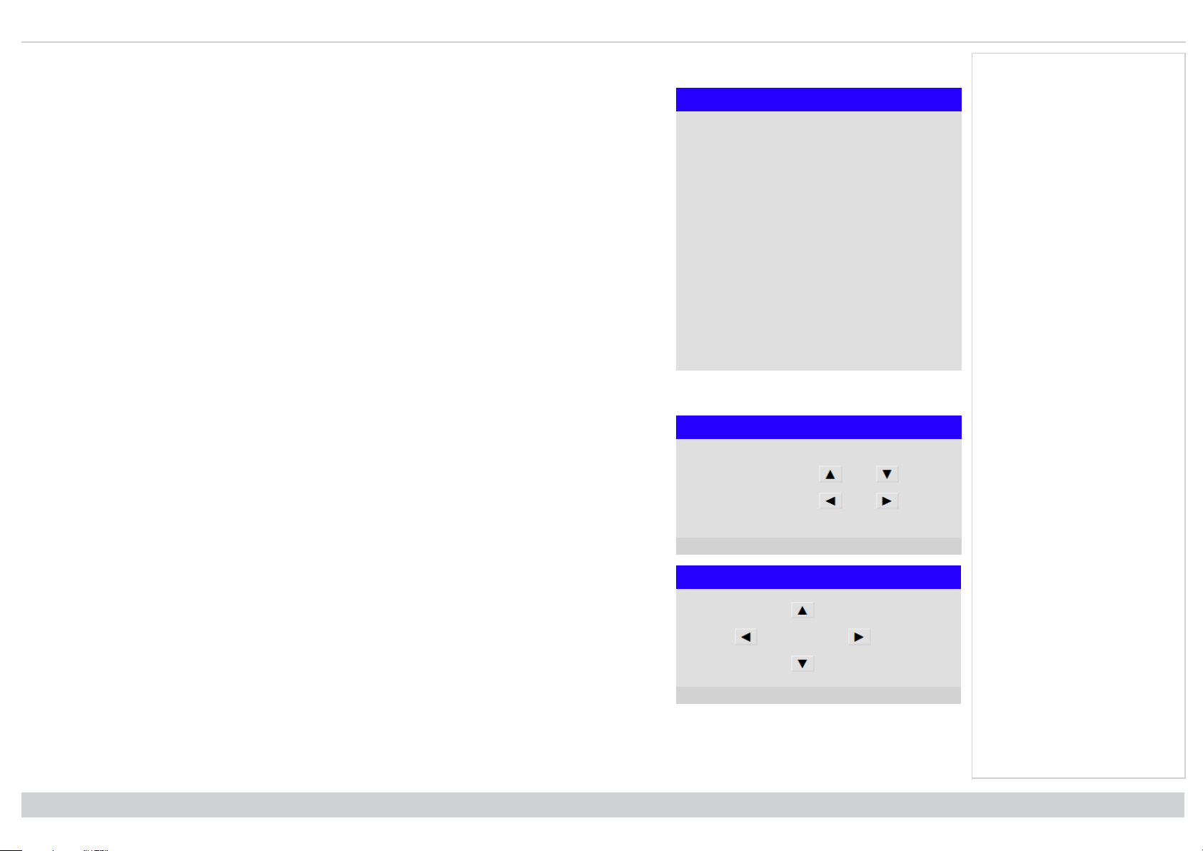
Inside a menu
When you open a menu, the page consists of the following elements:
l Title bar at the top shows which menu you have accessed.
l Highlighted item
l Available and unavailable items Unavailable items appear a pale gray color. Whether an item is
available may depend on other settings.
l The text or symbol to the right of an item shows whether the item:
l has a value that can be changed (the current value is shown)
l opens a sub-menu (an arrow button is displayed)
l executes a command (the space to the right of the item is blank).
Main Menu
▲
PIP ►
Information ►
OSD: Top Level Menu Continued
Menu Name
Highlighted Item Value
Menu Item Value
Unavailable Item Value
Slider Value
Sub-menu ►
Command
Notes
The highlighted item has
green background.
Operating Guide
Inside a menu
Rev A June 2019
page37
Page 38

Digital Projection Ltd. M-Vision Laser 21K Series Using the menus
Accessing sub menus
Use the UP and DOWN arrow buttons to highlight the sub-menu, then press ENTER/OK.
Executing commands
If the item contains a command, highlighting it reveals an OK
button.
Press ENTER/OK to execute the highlighted command.
You may be asked for confirmation. Use the ENTER/OK to
confirm, or EXIT to cancel.
Menu Item Value
Highlighted Command
Menu Name
Highlighted Command
Notes
Command Name
Warning
All [Menu] values will be lost.
Press OK to confirm
Press Exit to cancel
Confirmation Dialog
Rev A June 2019
page38
Operating Guide
Page 39

Using the menus Digital Projection Ltd. M-Vision Laser 21K Series
Editing projector settings
If the highlighted menu item contains a list of values to choose from, you can change the value by doing the
following:
1. Highlight the menu item and press ENTER/OK.
2. In the list of values that opens, use the UP and DOWN arrow buttons to highlight a value, then press
ENTER/OK again to select the highlighted value.
Using a slider to set a value
Some parameters open a slider. To set such a parameter:
1. Press the LEFT or RIGHT arrow button, or ENTER/OK. The arrow buttons will open the slider and adjust
the value at the same time. ENTER/OK will open the slider without altering the initial value.
2. Use the LEFT and RIGHT arrow buttons to move the slider.
3. When ready, press EXIT to exit the slider and return to the menu, or press MENU to exit the slider without showing the menu again.
Highlighted Item Current Value
Menu Item
Menu Item
Parameter Value
Menu Name
Highlighted Value
Value
Value
Value
List of Values
Slider
Notes
Some menu items may be
unavailable due to
settings in other menus.
Unavailable menu items
appear gray
Operating Guide
Rev A June 2019
page39
Page 40
Digital Projection Ltd. M-Vision Laser 21K Series Using the menus
Editing numeric values
Some parameters take numeric values without using sliders - for example, color matching values or IP
addresses.
1. Use the UP and DOWN arrow buttons to highlight the row containing the numeric field you wish to edit.
2. Press ENTER/OK to enter edit mode. A numeric field in edit mode is white text on blue background.
3. In edit mode:
l Use the UP arrow button to increase the numeric value.
l Use the DOWN arrow button to decrease the numeric value.
4. Use the LEFT and RIGHT arrow buttons to edit the next or previous numeric fields within the same row.
5. Once ready, press ENTER/OK to exit edit mode.
Notes
Data
Row x: 0.658 y: 0.339
Highlighted Row x: 0.315 y: 0.662
Row x: 0.146 y: 0.043
Row x: 0.276 y: 0.283
Rev A June 2019
page40
Operating Guide
Page 41

Using the projector Digital Projection Ltd. M-Vision Laser 21K Series
Using the projector
Main menu
l Input
Press ENTER/OK to open the list of available inputs.
Use the UP and DOWN arrow buttons to select an
input from the list, then press ENTER/OK to confirm
your choice. Press EXIT to return to the main menu.
l Test Pattern
Choose from: White, Black, Red, Green, Blue,
Checkerboard, Crosshatch, V Burst, H Burst, Color
Bar, Off. Use the LEFT and RIGHT arrow buttons to
switch between values.
l Lens, Image, Color, Geometry, Edge Blend, 3D,
Laser, Setup and Network.
Press ENTER/OK to open these menus and access
various settings.
Press the DOWN arrow at the bottom of the page to access
additional menus:
l PIP and Information
Press ENTER/OK to open these menus and access
various settings.
Press the UP arrow to return to the previous page.
Main Menu
Input HDMI 1
Test Pattern
Lens ►
Image ►
Color ►
Geometry ►
Edge Blend ►
3D ►
Laser ►
Setup ►
Network ►
▼
Main Menu, page 1
Main Menu
▲
PIP ►
Information ►
Main menu, page 2
Notes
See Signal inputs on
page28 for information
about the available inputs
and connections.
Selecting a test pattern
hides the OSD. Press
EXIT to hide the test
pattern, and then press
MENU to show the OSD
Operating Guide
Rev A June 2019
page41
Page 42
Digital Projection Ltd. M-Vision Laser 21K Series Using the projector
Lens menu
l Lens Lock
When this feature is On, all other Lens menu items are disabled.
l Lens Control
Opens a sub-menu, see below.
l Center Lens
Centers the lens.
l Lens Memory
Opens a sub-menu, see next page.
Lens control
Lens Control settings operate in Zoom/Focus Adjustment and Shift Adjustment mode. Press ENTER/OK to
switch between modes.
When in Zoom/Focus Adjustment mode:
l Use the UP and DOWN arrow buttons to adjust Zoom.
l Use the LEFT and RIGHT arrow buttons to adjust Focus.
Notes
Lens
Lens Lock Off
Lens Control ►
Center Lens
Lens Memory ►
Lens Control
Zoom
Focus
When in Shift Adjustment mode, use the arrow buttons to adjust Shift.
Rev A June 2019
page42
[OK] Shift Adjustment
Lens Control
Shift
[OK] Zoom / Focus Adjustment
Operating Guide
Page 43

Using the projector Digital Projection Ltd. M-Vision Laser 21K Series
Lens memory
This menu allows you to load, save and delete up to ten lens presets, containing horizontal and vertical shift
adjustment information.
Use Clear Memory to delete a memory preset if you need to save a new combination of lens settings in its
place. Overwriting a saved memory preset is not possible.
Lens Save Memory
Memory 1
Memory 2
Memory 3
Memory 4
Memory 5
Memory 6
Memory 7
Memory 8
Memory 9
Memory 10
Lens Load Memory
Memory 1
Memory 2
Memory 3
Memory 4
Memory 5
Memory 6
Memory 7
Memory 8
Memory 9
Memory 10
Lens Memory
Load Memory ►
Save Memory ►
Clear Memory ►
Lens Clear Memory
Memory 1
Memory 2
Memory 3
Memory 4
Memory 5
Memory 6
Memory 7
Memory 8
Memory 9
Memory 10
Notes
The lenses for the MVision series can only
store horizontal and
vertical shift information.
Zoom and focus memory
is not available.
Operating Guide
Rev A June 2019
page43
Page 44

Digital Projection Ltd. M-Vision Laser 21K Series Using the projector
Image menu
l Picture Mode
Choose from High Bright, Presentation and Video.
Use a different setting depending the type of input source.
Press ENTER/SELECT to open the list.
Use the UP and DOWN arrow buttons to select a picture mode from the list, then press ENTER/OK to
confirm your choice.
Press EXIT to return to the main menu.
l Dynamic Black
Set to On to allow for increased contrast in darker scenes by modulating the light source.
l Light Off Timer
When Dynamic Black is On, the Light Off Timer will define if laser light source will turn off after a period
of time has passed. The options are: Disable, 0.5, 1.0, 1.5, 2.0, 3.0, 4.0 seconds.
l Gamma
Choose a de-gamma curve from 1.0, 1.8, 2.0, 2.2, 2.35, 2.5, S-Curve, and DICOM.
Used correctly, the Gamma setting can improve contrast while maintaining good details for blacks and
whites.
If excess ambient light washes out the image and it is difficult to see details in dark areas, lower the
Gamma setting to compensate. This improves contrast while maintaining good details for blacks.
Conversely, if the image is washed out and unnatural, with excessive detail in black areas, increase the
setting.
S-Curve is an enhanced mid-tone gamma.
DICOM is a simulated DICOM display, which can be used for training applications.
l Brightness, Contrast, Saturation, Hue, Sharpness
Highlight the setting you wish to edit, and then press ENTER/OK, or the LEFT or RIGHT arrow button to open the slider.
Use the LEFT and RIGHT arrow buttons to adjust the slider.
Press EXIT to close the slider and return to the menu, or MENU to close the slider and return to the projected image.
l Noise Reduction
Choose a level of noise reduction from Off, Low, Middle and High.
l Freeze
Freezes the current frame.
l Resync
Press ENTER/OK to force the projector to resynchronise with the current input
Notes
Image
Picture Mode High Bright
Light Off Timer – – – –
Dynamic Black Off
Gamma 2.2
Brightness 100
Contrast 100
Saturation 100
Hue 100
Sharpness 10
Noise Reduction Off
Freeze
Resync
Rev A June 2019
page44
Operating Guide
Page 45

Using the projector Digital Projection Ltd. M-Vision Laser 21K Series
Color menu
Color space
In most cases, the Auto setting determines the correct colorspace to use. If it does not, you can choose a specific
colorspace:
Choose from Auto, YPbPr, YCbCr, RGB PC and RGB Video.
Color
Color Space Auto
Color Mode ColorMax
ColorMax Peak
Manual Color Matching ►
Color Temperature Native
Gains and Lifts ►
3 Color Matching ►
7 Color Matching ►
Color
Color Space Auto
Color Mode
ColorMax
Manual Color Matching
Color Temperature
Gains and Lifts
3 Color Matching
7 Color Matching
Auto
YPbPr
YCbCr
RGB PC
RGB Video
Notes
Operating Guide
Rev A June 2019
page45
Page 46

Digital Projection Ltd. M-Vision Laser 21K Series Using the projector
Color mode
The projector can work in the following color modes: ColorMax, Manual Color Matching, Color Temperature
and Gains and Lifts.
ColorMax
1. Set Color Mode to ColorMax.
2. Navigate to the ColorMax setting.
3. Choose from HDTV, Peak, User 1,User 2, 3 Color Matching and 7 Color Matching. User 1 and User 2
are user-defined color gamuts set via the Setup > ColorMax menu.
Color
Color Space Auto
Color Mode ColorMax
ColorMax
Manual Color Matching
Color Temperature
Gains and Lifts
3 Color Matching
7 Color Matching
ColorMax
ManualColor
Matching
ColorTemperature
Gains and Lifts
3 Color Matching
7 Color Matching
Color
Color Space Auto
Color Mode ColorMax
ColorMax Peak
Manual Color
Matching
Color Temperature
Gains and Lifts
3 Color Matching
7 Color Matching
HDTV
Peak
User 1
User 2
3 Color Matching
7 Color Matching
Notes
Only one color mode can
be selected at a time.
Settings used by the other
color modes are disabled.
See Setup menu on
page77 for further
information about setting
up the User 1 and User 2
color gamuts.
Rev A June 2019
page46
Operating Guide
Page 47
Using the projector Digital Projection Ltd. M-Vision Laser 21K Series
Manual color matching
1. Set Color Mode to Manual Color Matching.
2. Open the Manual Color Matching submenu.
Here you can do the following:
l Switch Auto Test Pattern On and Off.
l Adjust Hue, Saturation and Gain settings for each individual color to improve the color balance of the
projected image.
l Adjust white balance RGB values.
l Reset all values.
Manual Color Matching - Red
Hue 100
Saturation 100
Gain 100
Manual Color Matching
Auto Test Pattern Off
Red ►
Green ►
Blue ►
Yellow ►
Cyan ►
Magenta ►
White Balance ►
Reset
Manual Color Matching - White
Red 100
Green 100
Blue 100
Notes
See Color matching
parameters explained on
the next page for more
details about the Hue,
Saturation and Gain
settings.
Operating Guide
Rev A June 2019
page47
Page 48

Digital Projection Ltd. M-Vision Laser 21K Series Using the projector
Color matching parameters explained
The levels of hue, saturation and gain in the Manual Color
Matching menu change the color values in the following ways:
1. Hue Specifies the position of each color (red, yellow,
green, cyan, blue and magenta) relative to its
neighboring colors.
2. Saturation Specifies the level of white in each color
(i.e. how “pale” each color is).
3. Gain Controls the amount of light that goes into each
color, i.e. the lowest gain would produce black.
Notes
Rev A June 2019
page48
Operating Guide
Page 49

Using the projector Digital Projection Ltd. M-Vision Laser 21K Series
Color temperature
1. Set Color Mode to Color Temperature.
2. Navigate to the Color Temperature setting. Choose a value from 3200K (warmer) to 9300K (cooler) or
Native (no correction).
Gains and lifts
1. Set Color Mode to Gains and Lifts.
2. Open the Gains and Lifts submenu.
Lifts allow you to adjust black levels of individual colors, while gains adjust the bright part of the scale.
Set the sliders as required
Color
Color Space Auto
Color Mode Color Temperature
ColorMax Peak
Manual Color Matching ►
Color Temperature Native
Gains and Lifts
3 Color Matching
7 Color Matching
3200K
5400K
6500K
7500K
9300K
Native
Gains and Lifts
Red Lift 100
Green Lift 100
Blue Lift 100
Red Gain 100
Green Gain 100
Blue Gain 100
Notes
Operating Guide
Rev A June 2019
page49
Page 50
Digital Projection Ltd. M-Vision Laser 21K Series Using the projector
3 Color Matching
1. Set Color Mode to 3 Color Matching.
2. Open the 3 Color Matching submenu.
Here you can do the following:
l Switch Auto Test Pattern On and Off.
l Adjust the RGB settings for each individual color to alter its hue.
l Adjust the Gain value of the white balance.
l Reset all values.
3 Color Matching - Red
Red 100
Green 100
Blue 100
3 Color Matching
Auto Test Pattern Off
Red ►
Green ►
Blue ►
White Balance ►
Reset ►
3 Color Matching - White
Gain 100
Notes
In 3 color and 7 color
matching, the contribution
of red, green and blue can
be adjusted for each color.
This allows the tint of each
color to be matched
across multiple projectors.
Rev A June 2019
page50
Operating Guide
Page 51

Using the projector Digital Projection Ltd. M-Vision Laser 21K Series
7 Color Matching
1. Set Color Mode to 7 Color Matching.
2. Open the 7 Color Matching submenu.
Here you can do the following:
l Switch Auto Test Pattern On and Off.
l Adjust the RGB settings for each individual color to alter its hue.
l Adjust the Gain value of the white balance.
l Reset all values.
7 Color Matching - Red
Red 100
Green 100
Blue 100
7 Color Matching
Auto Test Pattern Off
Red ►
Green ►
Blue ►
Yellow ►
Cyan ►
Magenta ►
White Balance ►
Reset
7 Color Matching - White
Gain 100
Notes
In 3 color and 7 color
matching, the contribution
of red, green and blue can
be adjusted for each color.
This allows the tint of each
color to be matched
across multiple projectors.
Operating Guide
Rev A June 2019
page51
Page 52

Digital Projection Ltd. M-Vision Laser 21K Series Using the projector
Geometry menu
This menu allows you to compensate for image distortions caused by an unusual projection angle or irregular
screen surface.
Aspect ratio
This feature defines the aspect ratio of the source. Use the Setup > Screen Setting to define the screen aspect ratio.
If you choose a preset aspect ratio from here, it will give you the best fit for your selection.
Choose from:
l 5:4
l 4:3
l 16:10
l 16:9
l 1.88
l 2.35
l TheaterScope
l Source
l Unscaled
Geometry
Aspect Ratio Source
Digital Zoom ►
Overscan Off
Blanking ►
Warping Mode Keystone ►
Warping Grids Off
Custom Masking Off
Notes
Select the Warping Mode
you want to use before
opening its submenu.
Image scaling and aspect
ratio are also influenced
by Setup > Screen
Setting.
See Theaterscope setting
on the facing page for
further information about
the TheaterScope aspect
ratio.
Rev A June 2019
page52
Operating Guide
Page 53

Using the projector Digital Projection Ltd. M-Vision Laser 21K Series
Black margin – part of the source
Black margin – part of the source
Theaterscope setting
The TheaterScope setting is used in combination with an anamorphic lens to restore 2.35: images packed into a 16:9 frame. Such images are projected with black
lines at the top and bottom of the 16:9 screen to make up for the difference in aspect ratios.
Without an anamorphic lens and without the TheaterScope setting applied, a 16:9 source containing a 2.35:1 image looks like this:
If we change the setting to TheaterScope, the black lines will disappear but the image will stretch vertically to reach the top and bottom of the DMD™:
An anamorphic lens will stretch the image horizontally, restoring the original 2.35 ratio:
Notes
TheaterScope is used with
an anamorphic lens.
If you use TheaterScope,
set your screen aspect
ratio to 16:9.
Operating Guide
Rev A June 2019
page53
Page 54

Digital Projection Ltd. M-Vision Laser 21K Series Using the projector
Digital zoom
Digital zooming enlarges a section of the image, while the area outside the enlarged section is cropped out to
preserve the overall image size.
l Digital Zoom defines the level of zoom that needs to be applied. If Digital Zoom is set to 0, then the other
settings in the menu will be disabled.
l Digital Pan and Digital Scan specify the area that is being enlarged:
l Digital Pan adjusts the horizontal coordinates.
l Digital Scan adjusts the vertical coordinates.
The Reset command restores the default Digital Zoom, Digital Pan and Digital Scan values.
Digital Zoom
Digital Zoom 0
Digital Pan 0
Digital Scan 0
Reset
Notes
Digital Zoom is a
temporary setting and not
retained after an input
change or power cycle.
Rev A June 2019
page54
Operating Guide
Page 55

Using the projector Digital Projection Ltd. M-Vision Laser 21K Series
Overscan
Use this setting to compensate for noisy or badly defined image edges.
Crop removes unwanted artifacts from the edges of your image by cropping the edges.
Zoom increases the size of the image to force the edges off-screen
Geometry
Aspect Ratio Source
Digital Zoom ►
Overscan Off
Blanking
Warping Mode
Keystone
4 Corners
Rotation ►
Pincushion / Barrel ►
Arc ►
Custom Warp ►
Off
Crop
Zoom
Notes
Operating Guide
Rev A June 2019
page55
Page 56
Digital Projection Ltd. M-Vision Laser 21K Series Using the projector
Blanking
Use this feature to:
l fit an odd-sized screen;
l cut off timecode dots in the top line of a picture;
l cut off subtitles, etc.
Select the edge you wish to blank and use the LEFT and RIGHT arrow buttons to determine the amount of
correction.
Use the Reset command to restore blanked edges.
Notes
Blanking
Top 0
Bottom 0
Left 0
Right 0
Reset
Rev A June 2019
page56
Operating Guide
Page 57

Using the projector Digital Projection Ltd. M-Vision Laser 21K Series
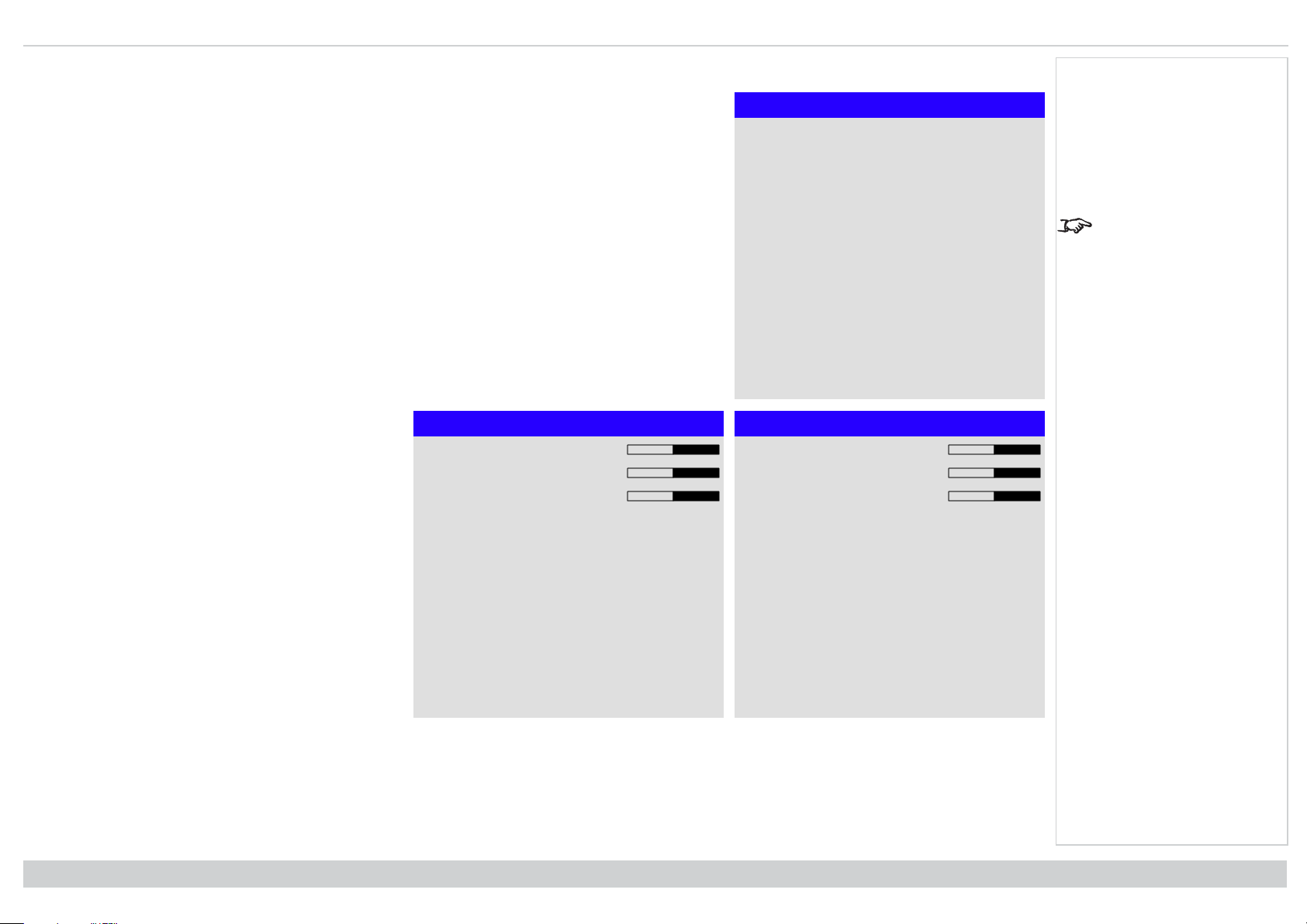
Keystone
Use this setting to compensate for any distortion caused by the projector being in a different horizontal or vertical
plane to the screen.
Keystone
H Keystone 0
V Keystone 0
Rotation 0
Reset
Notes
Max rotation in Keystone
is reduced from normal
rotation
Operating Guide
Rev A June 2019
page57
Page 58

Digital Projection Ltd. M-Vision Laser 21K Series Using the projector
Keystone example
Notes
The resulting image is distortedThe projector is positioned at an angle
The image is corrected when Keystone is
applied
Rev A June 2019
page58
Operating Guide
Page 59
Using the projector Digital Projection Ltd. M-Vision Laser 21K Series
1
2
3 4 5
Keystone settings
1. Projector to the left The projector is positioned to the
left of the screen. To correct, apply a positive
Horizontal Keystone value using the RIGHT arrow
button.
2. Projector to the right The projector is positioned to the
right of the screen. To correct, apply a negative
Horizontal Keystone value using the LEFT arrow
button.
3. Projector high The projector is positioned above the
screen at a downward angle. To correct, apply a
negative Vertical Keystone value using the DOWN
arrow button.
4. Projector low The projector is positioned below the
screen at an upward angle. To correct, apply a positive
Vertical Keystone value using the UP arrow button.
5. Projector straight The projector is directly opposite the
screen at a right angle both horizontally and vertically.
No correction is needed.
Notes
Operating Guide
Horizontal and vertical keystone corrections
Rev A June 2019
page59
Page 60
Digital Projection Ltd. M-Vision Laser 21K Series Using the projector
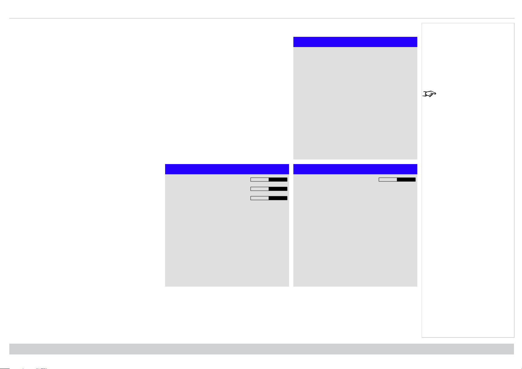
4 corners
For each corner, apply horizontal and / or vertical correction as necessary to restore the rectangular shape of the
image.
4 Corners
Top Left Corner ►
Top Right Corner ►
Bottom Left Corner ►
Bottom Right Corner ►
Reset
Notes
Corner corrections
provide a simple setup for
awkward installations and
irregular shaped screens
that may distort the image.
To apply a similar (but
less flexible) correction,
while preserving the
original aspect ratio of the
image, use the Keystone
menu.
Rev A June 2019
page60
Operating Guide
Page 61
Using the projector Digital Projection Ltd. M-Vision Laser 21K Series
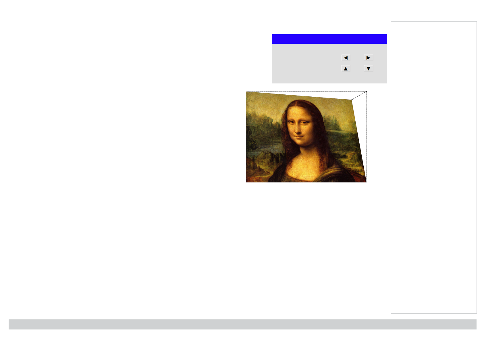
Top right corner example
In this illustration, the top right corner requires both horizontal and vertical correction.
Notes
Top Right Corner Adjustment
Top Right Corner x 0
Top Right Corner y 0
Operating Guide
Rev A June 2019
page61
Page 62

Digital Projection Ltd. M-Vision Laser 21K Series Using the projector
Rotation
Use this feature for example to correct a mounting error causing the image not to be level with the screen.
Notes
Rotation
Rotation 0
Reset
Rev A June 2019
page62
Operating Guide
Page 63
Using the projector Digital Projection Ltd. M-Vision Laser 21K Series
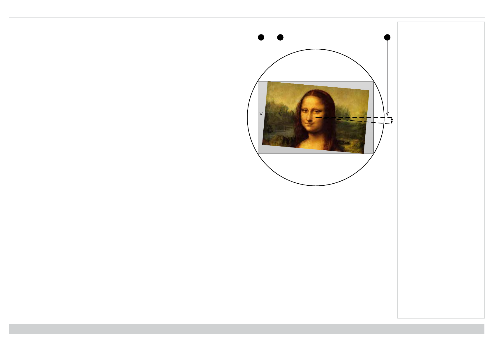
123
Rotation example
1. DMD™ area
The DMD™ is not rotated. It still covers the area that would be occupied by the image
without correction.
2. Rotated image
The image is smaller than the surrounding DMD™ area. It is scaled in order to remain within
the DMD™ area.
3. Angle of rotation
Each step on the slider is 0.25° of rotation. In this example the angle is 5°, therefore Rotation
value is 20.
Notes
Operating Guide
Rev A June 2019
page63
Page 64

Digital Projection Ltd. M-Vision Laser 21K Series Using the projector
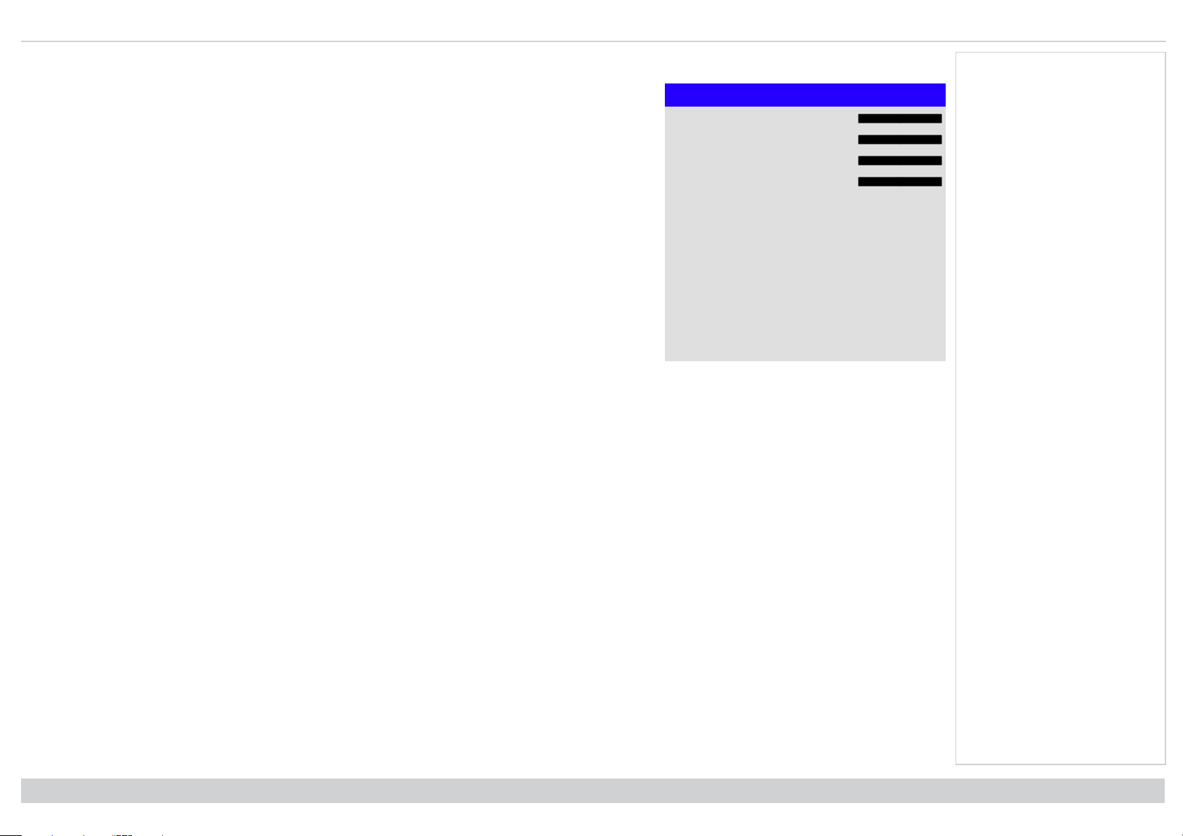
Pincushion / barrel
Pincushion or barrel distortions are the result of poor or incorrect tensioning of the screen or using a surface that
is not flat.
Use the Pincushion / Barrel control to compensate electronically for such distortions.
You can also use this menu to make simple panoramic screen corrections without using external processors.
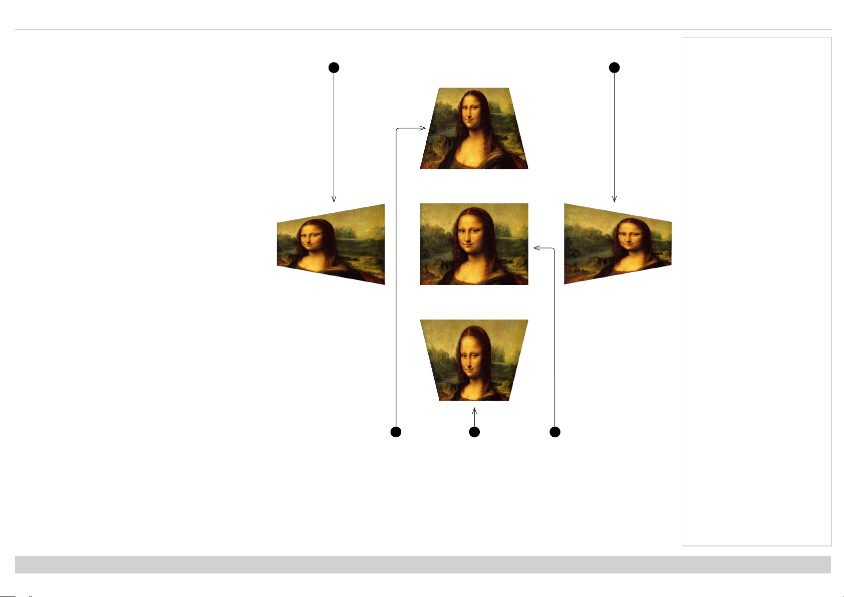
Pincushion/ Barrel example
The illustration shows pincushion
and barrel correction applied both
horizontally and vertically, in equal
measures.
Notes
Pincushion / Barrel
H Pin/Barrel 0
V Pin/Barrel 0
Keystone ►
Reset
Rev A June 2019
page64
BarrelPincushion
Operating Guide
Page 65

Using the projector Digital Projection Ltd. M-Vision Laser 21K Series
Arc
This feature is similar to Pincushion / Barrel but allows you to apply curvature to each edge of the image
independently so you can have any combination of corrections.
Arc
Top 0
Bottom 0
Left 0
Right 0
Reset
Notes
Please note that a positive
Arc value on any edge
will reduce the image size
as the projector needs to
maintain the aspect ratio.
A negative Arc value will
not affect the overall
image size.
Operating Guide
Rev A June 2019
page65
Page 66

Digital Projection Ltd. M-Vision Laser 21K Series Using the projector
Custom warp
This feature permits selection of predefined User warp maps. Use the Projector Controller PC application to
create the custom warp maps.
Custom warp maps provide non-linear curvature correction for curved or spherical screens and other irregular
shaped surfaces such as building mapping.
Notes
Custom Warp
Off
User 1
User 2
Rev A June 2019
page66
Operating Guide
Page 67

Using the projector Digital Projection Ltd. M-Vision Laser 21K Series
Warping grids
Switch warping grids on to overlay a grid onto the warped image.
Custom masking
This feature permits selection of predefined masks. Use the Projector Controller PC application to create the custom masks.
Use this feature to apply a custom mask to an area of the image. Select from Off, User 1 and User 2.
Notes
Operating Guide
Rev A June 2019
page67
Page 68
Digital Projection Ltd. M-Vision Laser 21K Series Using the projector
Edge blend menu
Use this menu to blend together images from an array of two or more projectors. The feature feathers the light
output of the projector within the edges that overlap with other projectors in the array: as a result, the
overlapping edges are evenly lit and easily blend in with the rest of the image.
l Edge Blend
Enable and disable Edge Blend
l Align Pattern
Add markers to the image showing the edges of the blend area and making the overlaps more visible to
help adjust the physical position of the projectors in the array.
l Blend Start
Determine the start point of the blended regions. top, bottom, left right
l Blend Width
Determine the width of the blended regions.
l Black Level Uplift
Adjust black levels to compensate if the blended regions appear brighter than the rest of the image.
l Reset
Reset all Edge Blend settings to their factory default values.
Edge Blend
Edge Blend On
Align Pattern Off
Blend Start ►
Blend Width ►
Black Level Uplift ►
Reset
Notes
When Edge Blend is set to
Off, all other edge blend
settings are disabled.
The picture in the blend
region needs to be
delivered to all
overlapping projectors,
which may require a
special setup of the
source.
Rev A June 2019
page68
Operating Guide
Page 69

Using the projector Digital Projection Ltd. M-Vision Laser 21K Series
123
4
Blend start
Use the blend start options to deactivate pixels at the edge of the image and set the start point for the blended
region. Use the LEFT and RIGHT arrow buttons to set the start point of the blended regions:
1. Top
2. Bottom
3. Left
4. Right
Notes
Blend Start
Top 0
Bottom 0
Left 0
Right 0
Operating Guide
Rev A June 2019
page69
Page 70

Digital Projection Ltd. M-Vision Laser 21K Series Using the projector
123
4
Blend width
Use the LEFT and RIGHT arrow buttons to set the width of the blended regions:
1. Top
2. Bottom
3. Left
4. Right
Notes
Blend Width
Top 0
Bottom 0
Left 0
Right 0
Rev A June 2019
page70
Operating Guide
Page 71

Using the projector Digital Projection Ltd. M-Vision Laser 21K Series
123
4
4
Black level uplift
Black in the blended regions appears less dark than in the rest of the image. To compensate for this, use this
menu to raise the black levels of the rest of the image:
l Set All to the required amount of black level correction. This will apply equal correction to the black
levels of all colors
l If necessary, use the individual color sliders (Red, Green and Blue) for fine adjustment.
You may experience artifacts at the edges where the blended region of one projector overlaps the pond of
mirrors of its neighbor. In the example below, the blended image comes from two projectors,1and2. Both
images have black level uplift applied; as a result, artifacts3and4have emerged at the edges where the
black level uplift region of one projector overlaps the pond of mirrors of the other.
To remove the artifacts, you need to slightly reduce the size of the black level uplift region of each projector so it
does not overlap the pond of mirrors of the other projector.
l Depending on your array, use Top, Bottom, Left and/or Right to reduce the black level uplift size. In the
example below, use the Right slider of the projector on the left1to remove the artifact on the right
, and the Left slider of the projector on the right2to remove the artifact on the left3.
Black Level Uplift
Select Area
Top 0
Bottom 0
Left 0
Right 0
Color Adjustment
All ◄ ►
Red 0
Green 0
Blue 0
Notes
Enable Align Pattern from
the Edge Blend menu to
see the black level uplift
area.
Operating Guide
Rev A June 2019
page71
Page 72

Digital Projection Ltd. M-Vision Laser 21K Series Using the projector
3D menu
Use this menu to enable, disable and set up 3D input, as follows:
l 3D Format — Off, Auto, Side-by-side, Top and Bottom, Dual Pipe and Frame Sequential.
Frame Sequential is for sources where Left and Right eye images are delivered as alternate frames from
a single input. Dual Pipe is for sources where Left and Right eye are delivered on separate inputs.
l DLP Link — Off / On.
DLP Link On emits a sync pulse for the 3D glasses via the projected image. DLP Link Off will send the
sync pulse to the sync out connector to use with an external third party emitter.
l Eye Swap — Normal and Reverse.
(set to Reverse if the left- and right-eye images are displayed in the wrong order)
l Dark Time — 0.65 ms, 1.3 ms and 1.95 ms.
Set to reduce the effect of banding and image overlapping when viewed through 3D glasses.
3D Sync
l Offset.
Use the LEFT and RIGHT arrow buttons to compensate for image overlapping (ghosting) when viewed
through 3D glasses.
l Reference— External and Internal.
Select the source of the 3D sync. Internal is referenced to the incoming video. External is for Frame
Sequential 3D sources and is supplied by the graphics card or player.
3D
3D Format Auto
DLP Link Off
Eye Swap Normal
Dark Time 1.95 ms
3D Sync
Offset 100
Reference Internal
Notes
If 3D Format is set to Off,
all other 3D settings will
be unavailable.
See 3D connections on
page30 for more
information about
supported 3D formats.
The following settings are
not available when 3D is
on:
Image >Picture Mode,
Dynamic Black, Freeze.
Geometry > Digital Zoom,
Overscan.
PIP > all settings.
Also: See 3D types on the
facing page and See
Some 3D settings
explained on page74
See 3D formats on
page105 for 3D
resolutions and frame
rates.
Rev A June 2019
page72
Operating Guide
Page 73

Using the projector Digital Projection Ltd. M-Vision Laser 21K Series
L
R
HDMI 1
HDMI 2
L R L R
3D types
To display a 3D image if is first necessary to select the 3D format. This can either be Frame Sequential or Dual Pipe. These formats are described below:
l Dual Pipe (LEFT and RIGHT) The left and right eye images are delivered on two separate
HDMI links, which the projector will interleave for 3D display.
l Frame Sequential For sequential 3D, an external sync is required to identify left and right
frames. If no sync is available from the sequential source, the projector will generate an
output sync, but it may then be necessary to manually set the Eye Swap each time the player
is started.
Dark Time and Sync Offset need to be set only once, to optimize the image for the glasses in use.
Dual Pipe
Notes
Operating Guide
Sequential
Rev A June 2019
page73
Page 74

Digital Projection Ltd. M-Vision Laser 21K Series Using the projector
Fully On
Fully Off
Left Right
Dark Time
Dark
Time
Dark
Time
LEFT 1 LEFT 2 LEFT 3RIGHT 1 RIGHT 2 RIGHT 3
LEFT 1 LEFT 2 LEFT 3RIGHT 1 RIGHT 2 RIGHT 3
Some 3D settings explained
Dark time
Banding can be caused if the image is displayed before each
eye of the 3D switching glasses or ZScreen is not fully open.
Dark Time allows you to minimize this effect.
Eye swap
The outgoing 3D frames are in pairs - the dominant frame
being presented first. You can determine which frame should
be the dominant one.
By convention the default setting is Left.
Notes
In order to achieve
maximum light output and
a smooth grayscale, whilst
eliminating ghosting, the
following procedure is
recommended:
1. Set Dark Time to a
value appropriate to the
glasses or ZScreen, say
1.3 ms or 1.95 ms.
2. Adjust Sync Offset time
to eliminate ghosting and
achieve a smooth
grayscale.
3. Repeat steps 1 and 2
until the best result is
obtained.
Dominance Left
Rev A June 2019
page74
Dominance Right
Operating Guide
Page 75

Using the projector Digital Projection Ltd. M-Vision Laser 21K Series
Incoming video
Incoming sync signal
Video signal with processing
delays (and dark time
adjustment)
Sync output signal after
delay adjustments
Sync offset
The sync signal from the 3D server will be in phase with the
frames generated by its graphics card. However, to
compensate for switching delays in the glasses or ZScreen,
Sync Offset is used to adjust the sync output signal sent to the
ZScreen or 3D glasses to minimise overlapping (ghosting in
the image when viewed through the 3D glasses.
Notes
Operating Guide
Rev A June 2019
page75
Page 76

Digital Projection Ltd. M-Vision Laser 21K Series Using the projector
Laser menu
l Power Mode
l Eco will automatically set the laser power to 80%.
l Normal will set the power to 100%.
l Set to Custom if you wish to adjust the power manually.
l Power Level
This setting is only available if Power Mode is set to Custom.
Choose a value between 20 and 100, ranging from 20% to 100% laser power.
l Constant Brightness
Once a Custom Power Mode has been set, then Constant Brightness can be turned ON.
This setting will maintain the brightness until the maximum laser power has been reached. The lower the
power level the longer it will be maintained.
Notes
Laser
Power Mode Normal
Power Level – – – –
Constant Brightness Off
Rev A June 2019
page76
Operating Guide
Page 77
Using the projector Digital Projection Ltd. M-Vision Laser 21K Series
Setup menu
l Orientation
Choose from Front Tabletop, Front Ceiling, Rear Tabletop, Rear Ceiling and Auto-front.
l High Altitude
Choose from On, Auto and Quiet.
l Standby Mode
Choose from SuperECO, ECO and Normal.
SuperECO uses minimal power and disables power ON via LAN.
ECO uses a low power setting but enables power ON via Ethernet port only.
Normal enables power ON via both HDBase-T/LAN and Ethernet ports.
l Screen Setting
Choose from 16:10, 16:9 and 4:3.
l ColorMax Setting
Set up user-defined color gamut values.
l Power On/Off
Access the submenu to set up automatic projector power on and power off.
l Clock Adjust
Access the submenu to set current date and local time.
l Startup Logo
Set this to On if you want the DP logo to show when the projector is first switched on.
l Blank Screen
Choose from Logo, Black, Blue and White.
l Auto Source
If this setting is On, the projector will automatically search for an active input source.
Setup
Orientation Auto-front
High Altitude Auto
Standby Mode Normal
Screen Setting 16:10
ColorMax Setting ►
Clock Adjust ►
Startup Logo On
Blank Screen Logo
Auto Source Off
OSD Settings ►
▼
Notes
Auto-front automatically
detects the projector’s
position and sets Table or
Ceiling orientation
accordingly.
Highlight the DOWN arrow at the bottom of the page and press ENTER/OK to navigate to the second Setup menu page.
Operating Guide
Rev A June 2019
page77
Page 78
Digital Projection Ltd. M-Vision Laser 21K Series Using the projector
l Trigger1 and Trigger 2
Setup
Choose from Screen, 5:4, 4:3, 16:10, 16:9, 1.88, 2.35, TheaterScope, Source, Unscaled or RS232 to
determine what will cause each trigger output to activate.
l Infrared Remote
Set to Off if you wish to disable the remote control.
l IR Code
The projector and the remote control need a matching IR code: a two-digit number between 00 and 99.
The default IR code is 00. This is also a master code, which, if assigned to a remote, will work regardless
of the value assigned to the projector.
l To assign an IR code for the projector: Select IR code. Use the UP and DOWN arrow buttons to
change the values.
l To assign an IR code for the remote, press and hold the ADDR button on the remote until the
On indicator starts flashing. Release the ADDR button and while the indicator is still flashing,
enter a two digit address using the numeric input buttons. The indicator will flash three times
Trigger-1 Off
Trigger-2 Off
Infrared Remote On
IR Code 0
IR Code Reset
OSD Settings ►
Memory ►
Electronic Shutter Enabled
EDID Mode ►
▲
quickly to confirm the change.
l IR Code Reset
Use this command to unassign an IR code from the projector. This will revert the IR Code value to 00.
To unassign an IR code from the remote control, press and hold ALT and ADDR simultaneously until
the On indicator flashes to confirm the change.
l OSD Settings
Access this submenu to adjust the appearance and position of the on-screen display.
l Memory
Access this submenu to save up to four presets containing custom combinations of image settings, or to recall a saved preset.
l Image Latency
Select Fast for improved latency.
Select Normal when image corruption occurs. Image corruption (frame tearing) may occur when a high level of warping is applied to the image and fast
latency is selected. See Geometry menu on page52 for information about image warping.
l Electronic Shutter
Set to On to turn the laser off when the PIC Mute activated.
Set to Off to project a black image when PIC Mute is activated.
l EDID Mode
Access this submenu to set the frame rate and display resolution for each input type.
Notes
The Projector Controller
software is available for
download from the Digital
Projection website, free of
charge.
A wired remote control will
also be disabled if
Infrared Remote is set to
Off.
Highlight the UP arrow at the top of the page and press ENTER/OK to go back to the first Setup menu page.
Rev A June 2019
page78
Operating Guide
Page 79

Using the projector Digital Projection Ltd. M-Vision Laser 21K Series
ColorMax
ColorMax permits seven point color matching of red, green, blue, yellow, cyan, magenta and white.
You can enter your own gamut values here, or edit values you have imported using the Projector Controller
software.
Defining your own colorspace with individual x and y coordinates for each color enables you to match not only
the whites but each individual color as well.
Highlight the submenu you wish to open and press ENTER/OK to confirm your choice.
Measured data/ target data
1. Use the UP and DOWN arrow buttons to highlight a
color, then use the LEFT and RIGHT arrow buttons to
navigate to the x or y coordinate.
2. Use the UP and DOWN arrow buttons to increase
and decrease the value, respectively.
3. Exit edit mode:
l press ENTER/OK, if you want to save the
edited values.
l press EXIT, if you do not wish to save the
edited values
4. If necessary, highlight another color and repeat the
procedure.
Red x: 0.658 y: 0.339
Green x: 0.315 y: 0.662
Blue x: 0.146 y: 0.043
White x: 0.276 y 0.283
Reset
Measured Data
ColorMax
Measured Data ►
Target Data - User1 ►
Target Data - User 2 ►
Target Data - User1
Red x: 0.640 y: 0.390
Green x:0.300 y: 0.600
Blue x: 0.150 y: 0.060
Yellow x: 0.419 y: 0.505
Cyan x: 0.225 y: 0.329
Magenta x: 0.321 y: 0.154
White x: 0.285 y: 0.302
Notes
The Projector Controller
software is available for
download from the Digital
Projection website, free of
charge.
This tool is best used in
conjunction with a
specialized light meter (a
photo spectrometer) to
measure color parameters
within a particular
installation. However, the
preloaded generic factory
default data set is
designed to give more
than satisfactory results.
Operating Guide
Rev A June 2019
page79
Page 80

Digital Projection Ltd. M-Vision Laser 21K Series Using the projector
Power on / off
l Auto Power Off
Set this to On if you want the projector to go into STANDBY mode when no input source is detected for
20 minutes.
l Auto Power On
Set this to On if you want the projector to start up immediately when the mains is connected. Set this to
Off if you want the projector to go into STANDBY mode when the mains is connected. In this case, the
projector will not start up until the POWER button is pressed on the control panel or the ON button is
pressed on the remote control.
l Scheduled on/off
Access this submenu to create a weekly schedule for automatic on and off times:
1. Set a schedule:
2. To enable the schedule, set Schedule to On.
l Use the UP and DOWN arrow buttons to highlight a row, then press ENTER/OK to enable
edit mode.
l Within a row, navigate with the LEFT and RIGHT arrow buttons. Set values with the UP
and DOWN arrow buttons.
l To exit edit mode, press ENTER/OK. Alternatively, press EXIT if you don’t want the
changes to take effect. Move to another row using the UP and DOWN arrow buttons.
Power on/off Management
Auto Power Off Off
Auto Power On Off
Scheduled on-off ►
Scheduled on-off
Schedule Off
S M T W T F S
On 12:34
Time
Notes
Rev A June 2019
page80
Off 12:34
On 12:34
Off 12:34
Operating Guide
Page 81

Using the projector Digital Projection Ltd. M-Vision Laser 21K Series
Clock adjust
Use this menu to set date (in dd:MM:yyyy format), time (in HH:mm format) and time zone.
The date and time set here will affect any schedule created within the Power On/Off menu.
OSDsettings
l Language sets the OSD language.
l Menu Position determines where the OSD should appear on the screen when activated.
l Menu Transparency sets OSD transparency between 0% (no transparency), 25%, 50% and 75%.
l Time Out determines how long the OSD should remain on screen if no buttons are pressed. Choose
Always On to disable this feature.
l Message Box determines whether projector status messages should appear on the screen.
l Menu RotationChoose from Off, Clockwise and Anticlockwise. Select a rotation option to rotate the
OSD menu when the projector is displaying in portrait.
Notes
Clock Adjust
Date (dd:MM:yyyy) 30:11:2017
Time (HH:mm) 16:00
Time Zone UTC 00
OSD Settings
Language English
Menu Position Center
Menu Transparency 0
Time Out 30 Seconds
Message Box On
Menu Rotation Off
Operating Guide
Rev A June 2019
page81
Page 82

Digital Projection Ltd. M-Vision Laser 21K Series Using the projector
Memory
The current image settings can be saved as a preset, which you can recall later. The default settings can be
recalled at any time as well.
Up to four custom presets can be stored for each input.
The following settings are saved in a preset:
l From the Image menu — Dynamic Black, Gamma, Brightness, Contrast, Saturation, Hue, Sharpness
and Noise Reduction
l From the Color menu — Color Space, Color Mode, ColorMax, Color Temperature, Dynamic Black,
RGB Lift and RGB Gain
l From the Geometry menu — Aspect Ratio and Overscan.
To recall a saved preset:
l Select Recall Memory and press ENTER/OK, then select a preset from Preset A to Preset D. Select
Default to load factory default values.
To save a preset:
l Select Save Settings and press ENTER/OK, then choose from Preset A, Preset B, Preset C and
Preset D.
EDID Mode
Each signal input type is available in the menu. Select the appropriate frame rate and display resolution for each
input.
Memory
Recall Memory Default
Save Settings Preset A
EDID Mode
HDMI 1 4K/60 HDR
HDMI 2 4K/60 HDR
HDMI 3 1920x1200xp60
HDMI 4 1920x1200xp60
DisplayPort 4K/60
HDBaseT 4K/60
Notes
Presets from one input
cannot be applied to
another input.
See on page1 for
information about the
parameters that can be
saved in a memory preset.
Rev A June 2019
page82
Operating Guide
Page 83

Using the projector Digital Projection Ltd. M-Vision Laser 21K Series
Network menu
l Network Mode
Choose between Projector Control and Service.
l DHCP, IP, Subnet Mask, Gateway, DNS
Set DHCP to On if the IP address is to be assigned by a DHCP server, or Off if it is to be set here.
If DHCP is On, it will not be possible to edit IP Address, Subnet Mask, Gateway or DNS.
If DHCP is set to Off, edit IP Address, Subnet Mask, Gateway and DNS as required.
l MAC This field is read-only.
l AMX Switch on or off
Notes
Network
Network Mode Projector Control
DHCP Off
IP 192.168 .000.10
Subnet Mask 255 .255 .255.000
Gateway 000.000.000 .000
DNS 000 .000 .000.000
MAC 00:18: 28:2d: f2: 06
AMX (Device Discovery) Off
Operating Guide
Rev A June 2019
page83
Page 84

Digital Projection Ltd. M-Vision Laser 21K Series Using the projector
PIP menu
l PIP Turn PIP on and off.
l Source Select an input source for the PIP image. Any combinations are possible between main and PIP
input source, as long as one of the inputs is either DisplayPort or 3G-SDI.
l Position Set the location of the PIP image on the screen. Choose from Top-Left, Top-Right, Bottom-Left,
Bottom-Right and PBP.
Notes
PIP
PIP Off
Source HDMI1
Position Top-Left
Rev A June 2019
page84
Operating Guide
Page 85

Using the projector Digital Projection Ltd. M-Vision Laser 21K Series
Information menu
This menu gives information about software and hardware configuration, input source and laser operating times
It also allows you to restore the factory default settings.
Signal format
Notes
Information
Model Name M-VisionLaser21K
Serial Number X000XXXXX0000
Software Version 1 MD03-SE10-FE09
Software Version 2 STEP_D08-24-17-3120
Software Version 3 2.0.16.0-P503
Active / PIP Source HDMI 1
Signal Format ►
Laser Hours 2
System Status ►
Thermal Status ►
Factory Reset
Signal Format
Active Source
Timing 1080p/60Hz
H Refresh 67.500 KHz
V Refresh 60.00 Hz
Pixel Clock 148.500 MHz
Operating Guide
PIP Source
Timing 576p/50Hz
H Refresh 31.250 KHz
V Refresh 50.00 Hz
Pixel Clock 27.0 MHz
Rev A June 2019
page85
Page 86

Digital Projection Ltd. M-Vision Laser 21K Series Using the projector
System status
Thermal status
Notes
System Status
Atmospheric Pressure 98988 Pa (116m)
AC Voltage 160V - 264V
Ceiling Mode 0
Tilt Angle 4 deg
Portrait Angle 0 deg
Altitude Mode Auto
Laser Power 100%
License Key License Pass,
Timeout,Not Expired
Constant Brightness Off
Thermal Status
Inlet Temp. Ti=24 / Ta=34 °C
DMD Temp. Tc=38 °C
LD 1-2 Temp. B8=56 / B15=52 °C
Fan 1-4 Speed 1399/1402 /1391/1686
Fan 5-8 Speed 1410/1200 /1205/1686
Fan 9-12 Speed 1211/ 1407 /1410/1691
Fan 13-16 Speed 1709/3005 /3007/ 2495
Fan 17-20 Speed 2986/2984 /4984/ 4493
Fan 20-23 Speed 3020/3015 /2517
Water Pump Speed 3506/3026
Rev A June 2019
page86
Operating Guide
Page 87

Using the projector Digital Projection Ltd. M-Vision Laser 21K Series
Factory reset
To restore the factory default settings:
1. Navigate to Factory Reset and press ENTER/OK.
2. When prompted, press ENTER/OK to confirm your choice, or press EXIT to cancel.
Information
Model Name M-Vision Laser 21K
Serial Number X000XXXXX0000
Software Version 1 MD03-SE10-FE09
Factory Reset
Warning
All user settings will be lost
Press OK to confirm
Press Exit to cancel
Thermal Status ►
Factory Reset
Notes
Factory reset does not
reset the Network settings,
or High Altitude mode
Operating Guide
Rev A June 2019
page87
Page 88

Digital Projection Ltd. M-Vision Laser 21K Series Served web pages
Served web pages
The served web pages allow you to control the projector remotely via LAN.
The default IP address is 192.168.0.100.
Notes
Rev A June 2019
page88
Operating Guide
Page 89

M-Vision Laser21K Series
High Brightness Digital Video Projector
REFERENCE GUIDE
Rev A June 2019
119-680
Page 90

Digital Projection Ltd. M-Vision Laser 21K Series Choosinga lens
Choosing a lens
A number of lenses are available. Which lens you choose depends on the screen size, image aspect ratio, throw distance and light output.
The following table shows all available lenses in order of their throw ratios:
Throw ratios Focus range Lens shift Part No
0.84 - 1.03 : 1 1.5 m - 10 m
1.20 - 1.56 : 1 zoom 1 m - 8 m
1.50 - 2.00 : 1 zoom 2 m - 12 m
2.00 - 4.00 : 1 zoom 2.5 m - 15 m
4.00 - 7.00 : 1 zoom 4 m - 42 m
To choose a lens, calculate the throw ratio required. Allow a tolerance of +/- 3% in the throw ratio calculation.
V: 0.37 (U) 0.37 (D)
H: 0.12 (L) 0.12 (R)
V: 0.5 (U) 0.5 (D) frame
H: 0.15 (L) 0.15 (R) frame
V: 0.5 (U) 0.3 (D) frame
H: 0.15 (L) 0.15 (R) frame
V: 0.5 (U) 0.3 (D) frame
H: 0.15 (L) 0.15 (R) frame
V: 0.5 (U) 0.3 (D) frame
H: 0.15 (L) 0.15 (R) frame
114-313
117-573
118-578
118-588
117-463
Notes
Rev A June 2019
page90
ReferenceGuide
Page 91

Choosing a lens Digital Projection Ltd. M-Vision Laser 21K Series
1
2
Basic calculation
Identify the required lens by calculating the throw ratio.
A throw ratio is the ratio of the throw distance2to the screen width1:
1. Use the formula above to obtain the required throw ratio.
2. Allow a tolerance of +/- 3% in the throw ratio calculation and match the throw ratio with a
lens from the table below:
Throw ratios Focus range
0.84 - 1.03 : 1 1.5 m - 10 m
1.20 - 1.56 : 1 zoom 1 m - 8 m
Notes
The basic calculation on
this page does not take
into consideration DMD™
and image size, which
could affect the throw
ratio.See Full lens
calculation on page93 for
a more complex and
realistic calculation.
When calculating the
throw ratio, be sure to use
identical measurement
units for both the throw
distance and the screen
width.
See Choosing a lens on
the previous page for
information about
individual lens part
numbers
1.50 - 2.00 : 1 zoom 2 m - 12 m
2.00 - 4.00 : 1 zoom 2.5 m - 15 m
4.00 - 7.00 : 1 zoom 4 m - 42 m
3. Ensure the required throw distance is within the range covered by the lens.
ReferenceGuide
Rev A June 2019
page91
Page 92
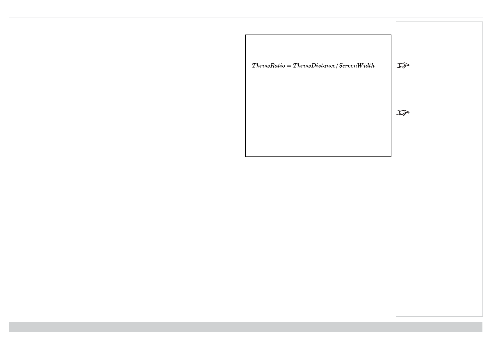
Digital Projection Ltd. M-Vision Laser 21K Series Choosinga lens
Basic calculation example
1. Calculate the throw ratio using the formula.
Your screen is 4.5m wide and you wish to place the projector approximately 11m from the
screen. The throw ratio will then be
11 ÷ 4.5= 2.44
2. Match the result with the lens table.
The lens matching a throw ratio of 2.44 is the 2.00 - 4.00 : 1 zoom lens .
3. Check whether the lens covers the required throw distance.
The focus range quoted for the 2.00 - 4.00 : 1 zoom lens is 2.5 - 15m.The required distance
of 11m is within the range.
INFORMATION YOU NEED FOR THIS CALCULATION
The throw ratio formula:
Allow a tolerance of +/- 3% in the throw ratio calculation.
The lens table:
Throw ratios Focus range
0.84 - 1.03 : 1 1.5 m - 10 m
1.20 - 1.56 : 1 zoom 1 m - 8 m
1.50 - 2.00 : 1 zoom 2 m - 12 m
2.00 - 4.00 : 1 zoom 2.5 m - 15 m
4.00 - 7.00 : 1 zoom 4 m - 42 m
Notes
The basic calculation on
this page does not take
into consideration DMD™
and image size, which
could affect the throw
ratio.See Full lens
calculation on the facing
page for a more complex
and realistic calculation.
See Choosing a lens on
page90 for information
about individual lens part
numbers.
Rev A June 2019
page92
ReferenceGuide
Page 93
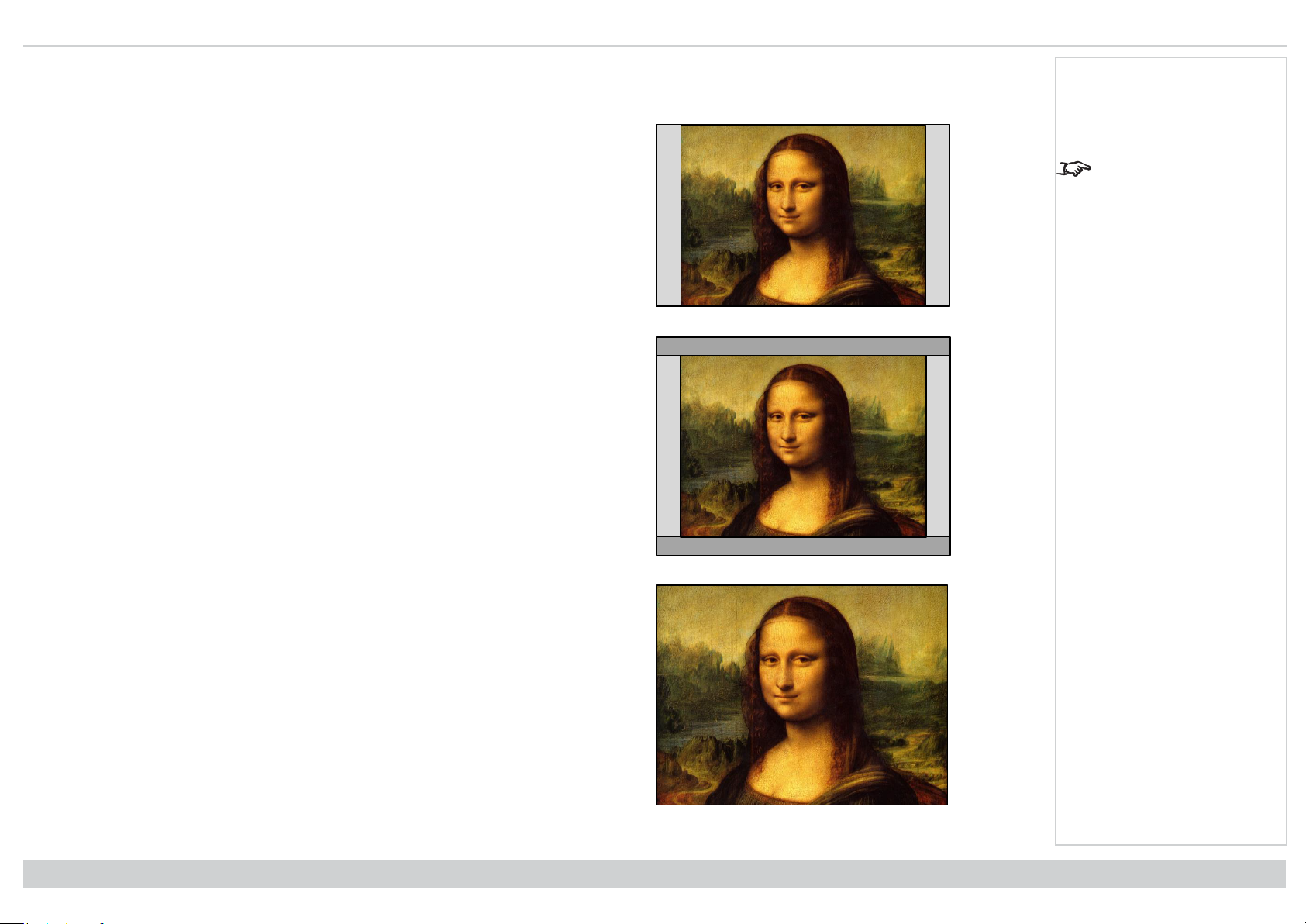
Choosing a lens Digital Projection Ltd. M-Vision Laser 21K Series
Fig 1
Fig 2
Fig 3
Full lens calculation
Introducing TRC
The choice of lens will affect the image size and will address discrepancies between the DMD™
resolution and the source.
When an image fills the height of the DMD™ but not the width, it uses less than 100% of the DMD™
surface. A lens chosen using the basic formula may produce an image that is considerably smaller
than the actual screen.
To compensate for loss of screen space in such situations, you need to increase the throw ratio
using a Throw Ratio Correction (TRC).
Example
Fig. 1 illustrates a 4:3 image within a 16:9 display
When a 16:9 projector is used for a 4:3 image, the image does not fill the width of the DMD™,
creating a pillarboxing effect - blank spaces to the left and right.
Fig. 2 shows the same image projected on a 4:3 screen using a standard lens (chosen with the
basic calculation).
The DMD™ accurately fills the width of the screen; however, the pillarboxing is now part of the
projected image and is transferred to the screen.
The DMD™ does not fill the height of the screen, which has caused letterboxing - further blank
spaces at the top and bottom of the screen.
The image is now surrounded by blank space, which can be removed if the throw ratio is increased.
Notes
TRC can only be applied if
greater than 1. If TRC is 1
or less, disregard it and
calculate the throw ratio
using the basic formula.
Fig. 3 shows the image projected on the same screen with a lens chosen using TRC. The increased
throw ratio has allowed the 4:3 image to fill the 4:3 screen seamlessly
ReferenceGuide
Rev A June 2019
page93
Page 94

Digital Projection Ltd. M-Vision Laser 21K Series Choosinga lens
Calculating TRC
To calculate TRC, use the following formula:
TRC table
Alternatively, you can save time by referencing the following table, which shows the TRC value for some popular image formats:
2.35:1 (Scope) 1920 x 817 pixels TRC < 1, not used
1.85:1 (Flat) 1920 x 1037 pixels TRC < 1, not used
1.78:1 (16:9) 1920 x 1080 pixels TRC < 1, not used
1.6:1 (16:10) 1920 x 1200 pixels TRC < 1, not used (native aspect ratio)
1.33:1 (4:3) 1596 x 1200 pixels TRC = 1.2
1.25:1 (5:4) 1500 x 1200 pixels TRC = 1.28
Calculating the throw ratio with TRC
1. For TRC > 1, amend the basic throw ratio formula as follows:
Allow a tolerance of +/- 3% in the throw ratio calculation.
2. Once a throw ratio is established, identify the matching lens from the table:
Throw ratios Focus range
0.84 - 1.03 : 1 1.5 m - 10 m
1.20 - 1.56 : 1 zoom 1 m - 8 m
1.50 - 2.00 : 1 zoom 2 m - 12 m
2.00 - 4.00 : 1 zoom 2.5 m - 15 m
4.00 - 7.00 : 1 zoom 4 m - 42 m
Notes
TRC can only be applied if
greater than 1. If TRC is 1
or less, disregard it and
calculate the throw ratio
using the basic formula.
TRC can only be applied if
greater than 1. If TRC is 1
or less, disregard it and
calculate the throw ratio
using the basic formula
3. Ensure the required throw distance is within the range of the matching lens.
Rev A June 2019
page94
ReferenceGuide
Page 95

Choosing a lens Digital Projection Ltd. M-Vision Laser 21K Series
Full lens calculation example
Your screen is 4.5m wide; you wish to place the projector approximately 11m from the screen.
The source is 4:3.
1. Calculate TRC as follows:
TRC = 1.6 / 1.33 = 1.2.
2. Calculate the throw ratio:
Throw ratio = 11 / 4.5 x 1.2 = 2.04
3. Allow a tolerance of +/- 3% in the throw ratio calculation and find a match in the lens
table.
The table shows that the matching lens is the 2.00 - 4.00 : 1 zoom lens.
4. Check whether the lens covers the required throw distance.
The focus range quoted for the 2.00 - 4.00 : 1 zoom lens is 2.5m - 15m. The required
distance of 11 m is within the range.
Notes
INFORMATION YOU NEED FOR THESE CALCULATIONS
The TRC formula
The TRC table (to use instead of the formula)
2.35:1 (Scope) TRC < 1, not used
1.85:1 (Flat) TRC < 1, not used
1.78:1 (16:9) TRC < 1, not used
1.6:1 (16:10) TRC < 1, not used (native aspect ratio)
1.33:1 (4:3) TRC = 1.2
1.25:1 (5:4) TRC = 1.28
The throw ratio formula
Allow a tolerance of +/- 3% in the throw ratio calculation.
The lens table:
ReferenceGuide
Throw ratios Focus range
0.84 - 1.03 : 1 1.5 m - 10 m
1.20 - 1.56 : 1 zoom 1 m - 8 m
1.50 - 2.00 : 1 zoom 2 m - 12 m
2.00 - 4.00 : 1 zoom 2.5 m - 15 m
4.00 - 7.00 : 1 zoom 4 m - 42 m
Rev A June 2019
page95
Page 96

Digital Projection Ltd. M-Vision Laser 21K Series Screen requirements
full width = 1920 pixels
2.35:1 (Scope)
= 817 pixels
16:10 (full height)
= 1200 pixels
16:9 1.78:1
= 1080 pixels
full height
= 1200 pixels
4:3 = 1.33:1 = 1596 pixels
full width = 1920 pixels
16:10 = 1.6:1 = 1920 pixels
Screen requirements
Fitting the image to the display
If the source image supplied to the projector is smaller than the WUXGA resolution, the image will not fill the display. The following examples show how a number
of common formats may be displayed, depending on your DMD™ resolution.
WUXGA images displayed full width
WUXGA images displayed with a height of 1200 pixels
Notes
Rev A June 2019
page96
ReferenceGuide
Page 97

Screen requirements DigitalProjection Ltd. M-Vision Laser 21K Series
4:3 = 1.33:1 = 1596 pixels
WUXGA = 16:10 = 1.6:1 = 1920 pixels
full height
= 1200 pixels
H = height
W = width
D = diagonal
WUXGA images displayed full height
Diagonal screen sizes
Screen sizes are sometimes specified by their diagonal size (D). When dealing with large screens
and projection distances at different aspect ratios, it is more convenient to measure screen width
(W) and height (H).
The example calculations below show how to convert diagonal sizes into width and height, at
various aspect ratios.
Notes
2.35:1 (Scope)
W = D x 0.92 H = D x 0.39
1.85:1
W = D x 0.88 H = D x 0.47
16:9 = 1.78:1
W = D x 0.87 H = D x 0.49
16:10 = 1.6:1 (native aspect ratio for WUXGA projectors)
W = D x 0.85 H = D x 0.53
ReferenceGuide
Rev A June 2019
page97
Page 98

Digital Projection Ltd. M-Vision Laser 21K Series Positioning the image
Shifting the lens up (rising front)
Centred Lens
Shifting the lens down (falling front)
Positioning the image
The normal position for the projector is at the centre of the
screen. However, you can set the projector above or below
the centre, or to one side, and adjust the image using the
Lens shift feature (known as rising and falling front) to
maintain a geometrically correct image.
Notes
See Lens control on
page42 for more
information on shifting the
lens.
Whenever possible,
position the projector so
that the lens is centered
for the highest quality
image
Rev A June 2019
page98
ReferenceGuide
Page 99

Positioningthe image Digital Projection Ltd. M-Vision Laser 21K Series
Combined shift is reduced
Full horizontal or vertical shift
Any single adjustment outside the
ranges specified on the following
page may result in an unacceptable
level of distortion, particularly at the
corners of the image, due to the
image passing through the
periphery of the lens optics.
If the lens is to be shifted in two
directions combined, the maximum
range without distortion will be
somewhat less, as can be seen in
the illustrations.
Notes
See Lens control on
page42 for more
information on shifting the
lens.
ReferenceGuide
Rev A June 2019
page99
Page 100

Digital Projection Ltd. M-Vision Laser 21K Series Aspect ratios explained
Aspect Ratio 16:10
1
1
Aspect Ratio: Source / 4:3
Aspect ratios explained
The appearance of a projected image on the screen depends on a combination of the following:
l The display resolution is WUXGA with a 1920 x 1200 resolution, corresponding to an aspect ratio of 16:10
l The aspect ratio of the input signal: usually 4:3, 16:9 or 16:10
l The value of the Aspect Ratio setting of the projector:
l 16:9, 4:3, 16:10 and 5:4 stretch the image to the selected aspect ratio. 16:9 leaves black bars at the top and bottom of the screen (letterboxing
effect); 4:3 and 5:4 leave black bars at the sides of the screen (pillarboxing).
l TheaterScope is a special setting used in combination with an anamorphic lens, an optional accessory. It removes letterboxing from a 2.35:1 source
packed into a 16:9 frame.
l Source shows the image with its original aspect ratio, if this does not match the native aspect ratio of the DMD
either fit the full width or height of the display.
Aspect ratios examples
1. Unused screen areas
Source: 4:3
TM
, then the image will be scaled to
Notes
Rev A June 2019
page100
ReferenceGuide
 Loading...