

Page 1
M-Vision Laser 18K Series
High Brightness Digital Video Projector
4INSTALLATION AND QUICK-START GUIDE
4CONNECTION GUIDE
4OPERATING GUIDE
4REFERENCE GUIDE
Rev C December 2017
118-056C
Page 2
Digital Projection M-Vision Laser 18K Series
About This Document
Follow the instructions in this manual carefully to ensure safe and long-lasting use of the projector.
Symbols used in this manual
Many pages in this document have a dedicated area for notes. The information in that area is accompanied by the following symbols:
WARNING: this symbol indicates that there is a danger of physical injury to yourself and/or damage to the equipment
unless the instructions are closely followed.
ELECTRICAL WARNING: this symbol indicates that there is a danger of electrical shock unless the instructions are closely
followed.
LIGHT HAZARD WARNING: this symbol indicates that there is a danger of exposure to intensive light that may result in
personal injury unless the instructions are closely followed.
LASER WARNING: this symbol indicates that there is a potential hazard of eye exposure to laser radiation unless the
instructions are closely followed.
NOTE: this symbol indicates that there is some important information that you should read.
Notes
Product revision
Because we at Digital Projection continually strive to improve our products, we may change specications and designs, and add new features
without prior notice.
Updates may be available online - visit the Digital Projection website for all latest documents.
Legal notice
Trademarks and trade names mentioned in this document remain the property of their respective owners.
Digital Projection disclaims any proprietary interest in trademarks and trade names other than its own.
Copyright © 2017 Digital Projection Ltd. All rights reserved.
Rev C December 2017
page i
Page 3
Digital Projection M-Vision Laser 18K Series
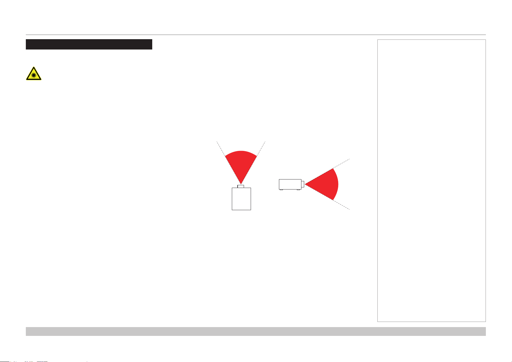
Risk Group 3 Information
Light hazard warning
Failure to comply with the following may result in serious injury:
• No direct exposure to the beam is permitted, RG3 IEC 62471-5:2015.
• Operators control access to the beam within the hazard distance or install the projector at sufcient height to prevent
exposures of spectators’ eyes within the hazard distance.
The hazard distance (Fig. 1) is the distance measured from the projection lens at which the intensity or energy per unit of surface is lower
than the applicable exposure limit on the cornea or skin. If the person is within the hazard distance, the beam is considered unsafe for
exposure.
The hazard distance for this projector is 600 cm.
Fig. 1: hazard distance
Notes
Rev C December 2017
page ii
Page 4
Digital Projection M-Vision Laser 18K Series
WIRED
REMOTE
RJ45
LAN
HDBaseT HDMI 1 DisplayPort 2DisplayPort 1 HDMI 2 3D SYNC - IN3G SDIIN3G SDI
OUT
3D SYNC - OUT
RS-2321 2TRIGGER
AC MAINS
交流電源輸入
AC POWER
SWITCH
交流電源開關
POWER
MENU EXIT
LENS
SHIFT
INPUT ASPECT PIC MUTE
AUTO
SYNC
CENTER
LENS
FOCUS ZOOM
3G SDI
OUT
3D SYNC - OUT
AC MAINS
交流電源輸入
AC POWER
SWITCH
交流電源開關
POWER
MENU EXIT
LENS
SHIFT
INPUT ASPECT PIC MUTE
AUTO
SYNC
CENTER
LENS
FOCUS ZOOM
CLASS 1 LASER PRODUCT
PRODUIT LASER DE CLASSE 1
GB 7247.1-2012 / IEC/EN 60825-1:2007
激光辐射
避免眼睛受到直接照射
3R类激光产品
波长 : 450-460 nm
最大脉冲能量: 0.48 mJ,
脉冲时间: 0.93 ms
激光輻射
避免眼睛受到直接照射
3R類激光產品
波長: 450-460 nm
最大脈衝能量: 0.48 mJ,
脈衝時間: 0.93 ms
RAYONNEMENT LASER
EXPOSITION DIRECTE DANGEREUSE
POUR LES YEUX
APPAREIL À LASER DE CLASSE 3R
longueur d'onde : 450-460nm
maximum énergie de impulsion : 0.48 mJ,
durée de impulsion : 0.93 ms
LASER RADIATION
AVOID DIRECT EYE EXPOSURE
CLASS 3R LASER PRODUCT
Emitted wavelength : 450-460 nm
Max. Pulse energy: 0.48 mJ,
Pulse duration: 0.93 ms
3262163400
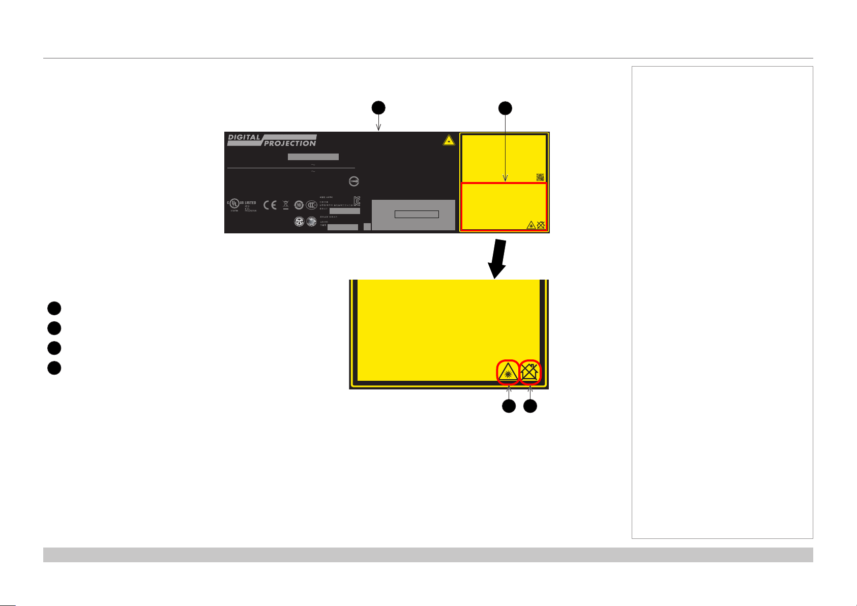
Light hazard labels on the body of the projector
Light hazard labelling is part of the product label.
(
數位投影機/数字投影机
M-Vision Laser yyyyyy
MSIP-REM-DVP-XXXXXXXXX
Product label
1
Risk Group 3 label
2
Hazard Warning symbol
3
Not For Home Use logo
4
DLP PROJECTOR / DLP Projecteur
Model/Modèle
AC Input / Entrée CA
AC Input / Entrée CA
制造商 : Digital Projection Limited
Greenside Way Middleton Manchester, M24 1XX UK
製造地:中國 / 制造地:中国 / Made in China
326XXXXXXX WJ XXXX
(型號 / 型号) :
(輸入 / 输入) : 200-240V 50/60Hz 9.3A
(輸入 / 输入) : 110-130V 50/60Hz 11.7A
:
KTLZUXXXXX-XXXXX
:
:
/ :
+822-515-5303
:
1
Complies with FDA performance standards for laser
products except for deviations pursuant to Laser
Notice No. 50, dated June 24, 2007
)
This device complies with part 15 of the FCC rules.
Operation is subject to the following two conditions:
(1) this device may not cause harmful interference, and
(2) this device must accept any interference received,
including interference that may cause undesired operation.
CAN ICES-3(A) /NMB-3(A)
警告使用者:此為甲類資訊技術設備,於居住環境中使用,可能會
造成射頻擾動,在此中情況下,使用者會被要求採取某些適當的對策。
R41086
RoHS
警告使用者: 此为A级产品,在生活环境中,该产品可能会造成无线
电干扰。在这种情况下,可能需要用户对干扰采取切实可行的措施。
Part No.: 118-053A
델타 비디오 디스플레이
시스템 (우장) 리미티드
QR
Code
Warning ! Do not look into the beam.
No direct eye exposure to the beam
Avertissement ! Ne Pas Regarder
Directement Dans Le Faisceau.
L’exposition Directe Des Yeux Au
Code 39 or 128 of serial no
*XXXXXXXXXXXXX*
MANUFACTURED YYYY.MM.DD
一类激光产品
IEC/EN 60825-1:2014
is permitted.
RG3
Hazard Distance : 0-600cm
Faisceau Est Interdite.
Distance À Risque : 0-600cm
RG3
LASER RADIATION
AVOID DIRECT EYE EXPOSURE
CLASS 3R LASER PRODUCT
Emitted wavelength : 450-460 nm
Max. Pulse energy: 0.48 mJ,
Pulse duration: 0.93 ms
RAYONNEMENT LASER
EXPOSITION DIRECTE DANGEREUSE
POUR LES YEUX
APPAREIL À LASER DE CLASSE 3R
longueur d'onde : 450-460nm
maximum énergie de impulsion : 0.48 mJ,
durée de impulsion : 0.93 ms
GB 7247.1-2012 / IEC/EN 60825-1:2007
CLASS 1 LASER PRODUCT
一类激光产品
IEC/EN 60825-1:2014
Warning ! Do not look into the beam.
No direct eye exposure to the beam
is permitted.
RG3
Hazard Distance : 0-600cm
Avertissement ! Ne Pas Regarder
Directement Dans Le Faisceau.
L’exposition Directe Des Yeux Au
Faisceau Est Interdite.
RG3
Distance À Risque : 0-600cm
第一類雷射產品
IEC/EN 60825-1:2014
眼睛不要直接暴露于光辐射 。
眼睛不要直接暴露於光輻射。
警告 !请勿直视镜头。
RG3
危险距离:0-600厘米
警告 ! 請勿直視鏡頭。
RG3
危險距離:0-600公分
2
激光辐射
避免眼睛受到直接照射
3R类激光产品
波长 : 450-460 nm
最大脉冲能量: 0.48 mJ,
脉冲时间: 0.93 ms
激光輻射
避免眼睛受到直接照射
3R類激光產品
波長: 450-460 nm
最大脈衝能量: 0.48 mJ,
脈衝時間: 0.93 ms
PRODUIT LASER DE CLASSE 1
第一類雷射產品
IEC/EN 60825-1:2014
警告 !请勿直视镜头。
眼睛不要直接暴露于光辐射 。
RG3
危险距离:0-600厘米
警告 ! 請勿直視鏡頭。
眼睛不要直接暴露於光輻射。
RG3
危險距離:0-600公分
Notes
3262163400
43
Rev C December 2017
page iii
Page 5
Digital Projection M-Vision Laser 18K Series
Laser Information
LASER LIGHT
AVOID DIRECT EYE EXPOSURE
CLASS 3R LASER PRODUCT
455-470nm <13Watts
CLASSIFIED EN/IEC 60825-1 2007
Caution - use of controls or adjustments or performance of procedures other than those specied herein may result in
hazardous radiation exposure.
Notes
Rev C December 2017
page iv
Page 6
Digital Projection M-Vision Laser 18K Series
Introduction
Congratulations on your purchase of this Digital Projection product.
Your projector has the following key features:
• WUXGA native resolution projector delivering 18,000 ISO lumens.
• Support for Frame Sequential and Dual Pipe 3D formats as well as Frame Packed, Side-by-Side etc. formats.
• HDBaseT® for transmission of uncompressed High Denition Video up to 100 m from the source.
• 3G-SDI with loop-through.
• Blanking control for custom input window sizing.
• Edge Blending with black level correction.
• Cornerstone, Vertical & Horizontal Keystone, Pincushion & Barrel, and Image Rotation.
• Non-Linear warp for irregular projection surfaces.
• Separate control of screen and source aspect ratio.
• Contstant brightness mode maintains light output at selected levels.
• Control via LAN and RS232.
• Motorised lens mount.
Notes
A serial number is located on the side of the projector. Record it here:
Rev C December 2017
page v
Page 7

Digital Projection M-Vision Laser 18K Series
CONTENTS
INSTALLATION AND QUICK-START GUIDE ..............................1
WHAT’S IN THE BOX?
CONNECTING THE POWER SUPPLY
PROJECTOR OVERVIEW
Front and rear views
Control panel
Projector indicators ................................................................................ 7
REMOTE CONTROL
Infrared reception
POSITIONING THE SCREEN AND PROJECTOR
Roll and pitch
Stacking instructions
CHANGING THE LENS
Inserting a new lens
Removing the lens
OPERATING THE PROJECTOR
Switching the projector on
Switching the projector off
Selecting an input signal
Selecting a test pattern
Adjusting the lens
Adjusting the image............................................................................. 21
................................................................... 3
............................................. 4
............................................................... 5
............................................................................. 5
......................................................................................... 6
....................................................................... 8
................................................................................ 11
........................... 12
...................................................................................... 13
........................................................................... 14
................................................................. 17
............................................................................ 17
.............................................................................. 18
.................................................... 19
................................................................... 19
................................................................... 19
..................................................................... 20
....................................................................... 20
................................................................................ 21
CONNECTION GUIDE ............................................................................23
SIGNAL INPUTS AND OUTPUTS
Digital inputs and outputs
EDID on the DisplayPort, HDMI and HDBaseT inputs
Using DisplayPort/HDMI/HDBaseT switchers with the projector
3D connections
Frame sequential 1080p and WUXGA 3D sources at 100 and 120 Hz ............... 27
Dual Pipe 1080p, WUXGA and WQXGA 3D sources at 100 and 120 Hz ............27
................................................................................... 27
3D Sync............................................................................................... 28
3D Sync In ......................................................................................... 28
3D Sync Out ....................................................................................... 28
CONTROL CONNECTIONS
LAN connection examples
RS232 connection example
.................................................. 25
.................................................................... 25
........................ 26
........ 26
........................................................... 29
.................................................................. 30
............................................................... 31
Rev C December 2017
page vi
Page 8

Digital Projection M-Vision Laser 18K Series
CONTENTS (continued)
OPERATING GUIDE ................................................................................33
USING THE MENUS
Opening the OSD
Opening a menu.................................................................................. 35
Exiting menus and closing the OSD.................................................... 35
Inside a menu...................................................................................... 36
Accessing sub-menus ........................................................................... 36
Executing commands............................................................................ 36
Editing projector settings
Using a slider to set a value .................................................................... 37
Editing numeric values .......................................................................... 37
USING THE PROJECTOR
Main menu
Lens menu
Lens Control ....................................................................................... 39
Lens Memory ...................................................................................... 40
Image menu
Color menu.......................................................................................... 42
Color Space ....................................................................................... 42
Color Mode ........................................................................................ 43
Geometry menu
Aspect Ratio ....................................................................................... 48
Digital Zoom ....................................................................................... 50
Overscan ........................................................................................... 51
Blanking ............................................................................................ 52
Keystone ........................................................................................... 53
4 Corners .......................................................................................... 55
..................................................................... 35
................................................................................ 35
..................................................................... 37
............................................................. 38
.......................................................................................... 38
.......................................................................................... 39
........................................................................................ 41
.................................................................................. 48
Rotation ............................................................................................ 56
Pincushion / Barrel ............................................................................... 57
Arc ................................................................................................... 58
Custom Warp ..................................................................................... 58
Edge Blend menu................................................................................ 59
Blend Width........................................................................................ 60
Black Level Uplift ................................................................................. 61
3D menu.............................................................................................. 62
3D types ............................................................................................ 63
Some 3D settings explained ................................................................... 64
Laser menu
Setup menu
ColorMax Setting ................................................................................. 68
Power On/Off ...................................................................................... 69
Clock Adjust ....................................................................................... 70
OSD Settings ...................................................................................... 71
Memory ............................................................................................. 71
Network menu
PIP menu
Information menu
Signal Format ..................................................................................... 74
System Status .................................................................................... 75
Thermal Status.................................................................................... 75
Factory Reset ..................................................................................... 76
......................................................................................... 65
......................................................................................... 66
..................................................................................... 72
............................................................................................ 73
................................................................................ 74
Rev C December 2017
page vii
Page 9

Digital Projection M-Vision Laser 18K Series
CONTENTS (continued)
REFERENCE GUIDE ................................................................................77
THE DMD™
CHOOSING A LENS
Basic calculation
Basic calculation example
Full lens calculation
Full lens calculation example
POSITIONING THE SCREEN AND PROJECTOR
POSITIONING THE IMAGE
FRAME RATES AND PULLDOWNS EXPLAINED
Interlaced and progressive scan
Frame rates of image sources
Pulldowns - conversion into destination formats
APPENDIX A: LENS PART NUMBERS
APPENDIX B: SUPPORTED SIGNAL INPUT MODES
2D formats........................................................................................... 95
3D formats........................................................................................... 98
.................................................................................. 79
..................................................................... 81
................................................................................. 82
................................................................... 83
............................................................................. 84
Introducing TRC .................................................................................. 84
Calculating TRC .................................................................................. 85
Calculating the throw ratio with TRC ......................................................... 86
.............................................................. 87
........................... 88
........................................................... 89
........................... 91
......................................................... 91
............................................................ 91
................................. 92
2:3 (normal) pulldown ........................................................................... 92
2:3:3:2 (advanced) pulldown ................................................................... 93
.......................................... 94
.................... 95
APPENDIX D: GLOSSARY OF TERMS
....................................... 102
APPENDIX C: WIRING DETAILS
RS232
Trigger 1 & Trigger 2
Wired remote control
Sync IN and Sync OUT
............................................................................................... 100
......................................................................... 101
......................................................................... 101
..................................................................... 101
................................................ 100
Rev C December 2017
page viii
Page 10

Digital Projection M-Vision Laser 18K Series
This page is intentionally left blank.
Page 11
M-Vision Laser 18K Series
High Brightness Digital Video Projector
4
INSTALLATION AND QUICK-START GUIDE
Rev C December 2017
Page 12

Digital Projection M-Vision Laser 18K Series
IN THIS GUIDE
IN THIS GUIDE
WHAT’S IN THE BOX? .....................................................................................3
CONNECTING THE POWER SUPPLY
PROJECTOR OVERVIEW
Front and rear views ...................................................................................................5
Control panel ...............................................................................................................6
Projector indicators ........................................................................................................... 7
REMOTE CONTROL
Infrared reception ......................................................................................................11
.................................................................................5
..........................................................................................8
POSITIONING THE SCREEN AND PROJECTOR
Roll and pitch ............................................................................................................13
Stacking instructions ................................................................................................14
CHANGING THE LENS
Inserting a new lens ..................................................................................................17
Removing the lens ....................................................................................................18
..................................................................................17
OPERATING THE PROJECTOR
Switching the projector on .......................................................................................19
Switching the projector off .......................................................................................19
Selecting an input signal ..........................................................................................20
Selecting a test pattern .............................................................................................20
Adjusting the lens .....................................................................................................21
Adjusting the image ..................................................................................................21
...........................................................4
.....................................12
...................................................................19
Installation and Quick-Start Guide
Rev C December 2017
Page 13
Digital Projection M-Vision Laser 18K Series
PicMute
OFF
ON
MENU
EXIT INFO
HDMI1
OK
OFF ON
ALT
LENS
FOCUS ZOOM
IN
OUT
IN
OUT
SHIFT
21 3
HDMI2 DVI
DISPLAYPORT
HD-T 3GSDI
VGA COMP1 COMP2
BRI
TEST
CON GAMMA
R G B ALL
3D EYE PIP SWAP
4 5 6
7 8 9 0
ALT
ADDR
OSD
OFF
ON
DEFAULT
FREEZE
RE-SYNC
A B C D
USERPRESET
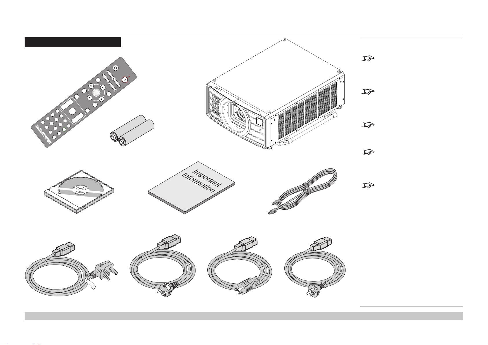
WHAT’S IN THE BOX?
What’s In The Box?
Remote control
2x AAA batteries
Projector
Notes
Make sure your box contains
everything listed. If any pieces are
missing, contact your dealer.
You should save the original box
and packing materials, in case you
ever need to ship your projector.
The projector is shipped without a
lens.
Only one power cable - dependent
on the destination territory - will be
supplied with the projector.
A stacking kit is also provided in
some regions.
User Manual on disc Important Information
Power cable, United Kingdom Power cable, China
Installation and Quick-Start Guide
HDMI cable
Power cable, Europe Power cable, North America
Rev C December 2017
page 3
Page 14
Digital Projection M-Vision Laser 18K Series
CONNECTING THE POWER SUPPLY
Connecting The Power Supply
Firmly push the mains connector into the socket 1, then press the ON/OFF switch 2.
1 2
Notes
Use only the power cable
provided.
Ensure that the power outlet
includes a ground connection as
this equipment MUST be earthed.
Handle the power cable carefully
and avoid sharp bends. Do not
use a damaged power cable.
When operating on 110V Light
output power is reduced by approx
35%.
Installation and Quick-Start Guide
Rev C December 2017
page 4
Page 15
Digital Projection M-Vision Laser 18K Series
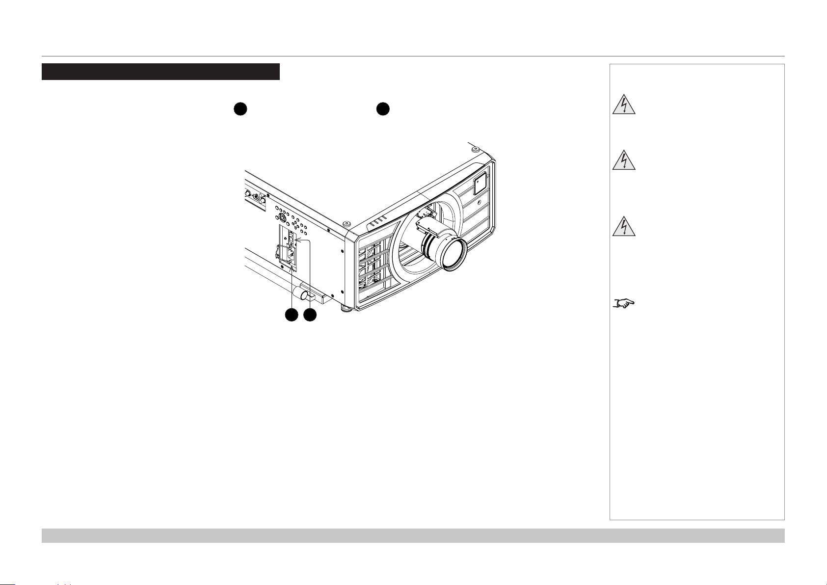
PROJECTOR OVERVIEW
Projector Overview
Front and rear views
Indicators: TEMP, LIGHT, STATUS and POWER
1
Lens mount
2
Air inlet
3
Lifting handle
4
Air inlet
5
Front infrared window
6
Stacking feet
7
Air outlet
8
Rear infrared window
9
Connections panel
10
1
2
5
6
3
4
7
Notes
Front view
12108
119
Lifting handle
11
Control panel
12
Adjustable feet
13
Stacking feet
14
Mains socket and switch
15
Installation and Quick-Start Guide
14 1513
Rear view
Rev C December 2017
page 5
Page 16
Digital Projection M-Vision Laser 18K Series
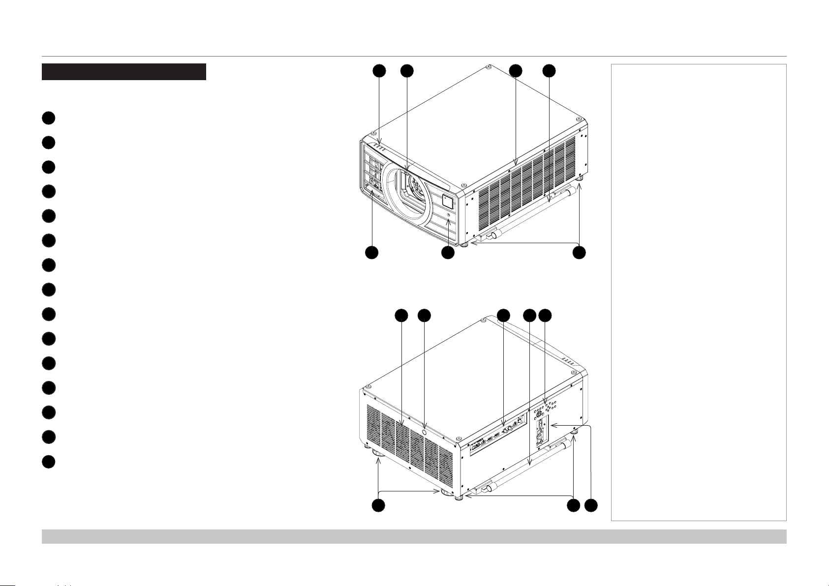
PROJECTOR OVERVIEW
Control panel
POWER
1
2
3
4
5
6
7
8
9
10
11
12
Switches the projector on and off
(STANDBY).
INPUT
Switches to the next input source.
AUTO SYNC
Re-synchronises with the current input
signal.
ASPECT
Changes the aspect ratio.
CENTER LENS
Centers the lens.
PIC MUTE
Shows and hides the projected image.
When OFF, the light source is completely
switched off and the screen is black.
MENU
Displays and exits the OSD.
Arrow buttons & ENTER
Navigation buttons used to highlight menu
entries in the OSD.
Press ENTER to open or execute the
highlighted menu entry.
EXIT
Exits the current OSD page and enters the
level above.
LENS SHIFT arrow buttons
Each of these buttons moves the lens in the
specied direction.
FOCUS plus and minus buttons
Used to move the focus in and out.
ZOOM plus and minus buttons
Used to zoom in and out.
1 2 3 4 5 6
POWER
7 8 9 10 11 12
INPUT
AUTO
SYNC
ASPECT
CENTER
LENS
PIC MUTE
Notes
AUTO SYNC and ASPECT do not
work when the projector uses HDMI
3 or 4.
Installation and Quick-Start Guide
Rev C December 2017
page 6
Page 17
Digital Projection M-Vision Laser 18K Series
PROJECTOR OVERVIEW
Projector indicators
TEMP. Off = no problem
Flashing red = temperature error
LIGHT Off = light is switched off
Flashing green = light is preparing to switch on
Flashing red (cycles of six ashes) = light module failure
On, green = light is switched on
STATUS Off = no problem
Flashing red (continuously) = cover error
Flashing red (cycles of four ashes) = fan error
On, red = system error
POWER Off = the projector is switched off
Flashing green = the projector is warming up
Flashing amber = the projector is cooling down
On, red = STANDBY mode
On, green = the projector is switched on
Notes
POWERSTAT U SLIGHTTEMP.
Installation and Quick-Start Guide
Rev C December 2017
page 7
Page 18
Digital Projection M-Vision Laser 18K Series
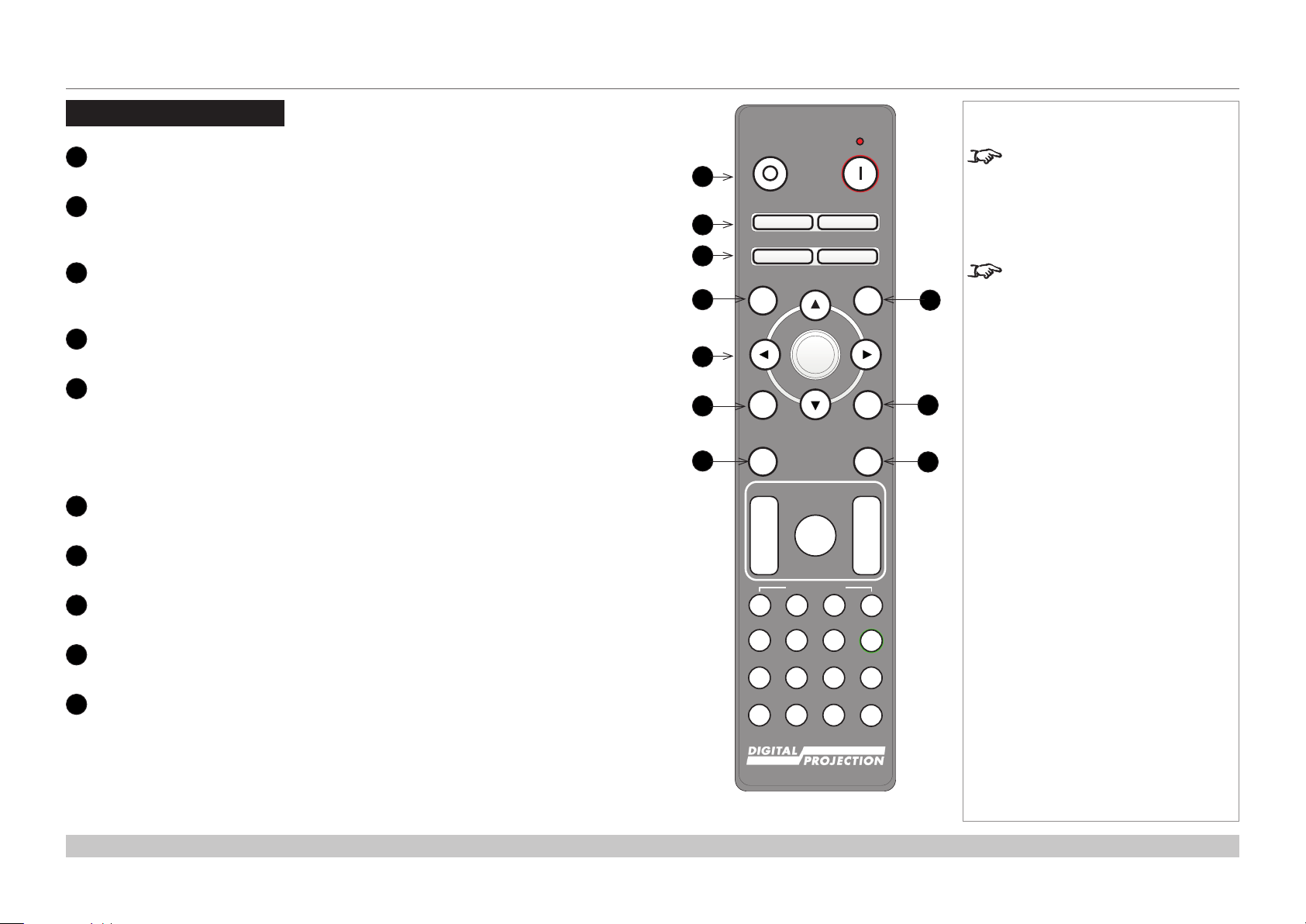
REMOTE CONTROL
Remote Control
1
Power ON / OFF
Turns power on and off.
2
Pic Mute OPEN / CLOSED
Shows and hides the projected image.
When CLOSED, the light source is completely switched off and the screen is black.
2
OSD ON / OFF
Enable and disable screen timeout messages and control whether to show the OSD
during projection.
4
MENU
Access the OSD. If the OSD is open, press this button to go back to the previous menu.
5
Navigation (arrows and OK)
Navigate through the menus with the arrows, conrm your choice with OK.
In lens adjustment modes, the arrows are used to move, zoom or focus the lens. See 11
below.
In lens adjustment modes, or when the OSD is not showing, the OK button switches
between modes: Shift Adjustment and Zoom / Focus Adjustment.
6
EXIT
Go up one level in the OSD. When the top level is reached, press to close the OSD.
7
FREEZE
Freeze the current frame.
8
DEFAULT
When editing a parameter, press this button to restore the default value.
9
INFO
Access information about the projector.
10
RE-SYNC
Re-synchronise with the current input signal.
Notes
OFF ON
1
Pic Mute
2
3
4
5
6
7
OPEN
OFF
MENU
EXIT INFO
FREEZE
FOCUS ZOOM
IN
OUT
USER PRESET
CLOSE
OSD
ON
DEFAULT
8
OK
9
RE-SYNC
10
LENS
IN
SHIFT
OUT
A B C D
HDMI2 DVI
HDMI1
HDMI3
DisplayPort1
21 3
DisplayPort2
HDMI4
HD-T 3GSDI
ALT
ALT
ADDR
4 5 6
R G B ALL
VGA COMP1 COMP2
7 8 9 0
3D EYE PIP SWAP
TEST
FREEZE and RE-SYNC are not
available when the projector uses
input HDMI 3 or 4.
This projector does not use the
following options on the remote:
DVI, VGA, COMP 1 and COMP 2.
continues on next page...
Installation and Quick-Start Guide
Remote control
Rev C December 2017
page 8
Page 19
MENU
EXIT INFO
OK
OSD
OFF
ON
DEFAULT
Digital Projection M-Vision Laser 18K Series
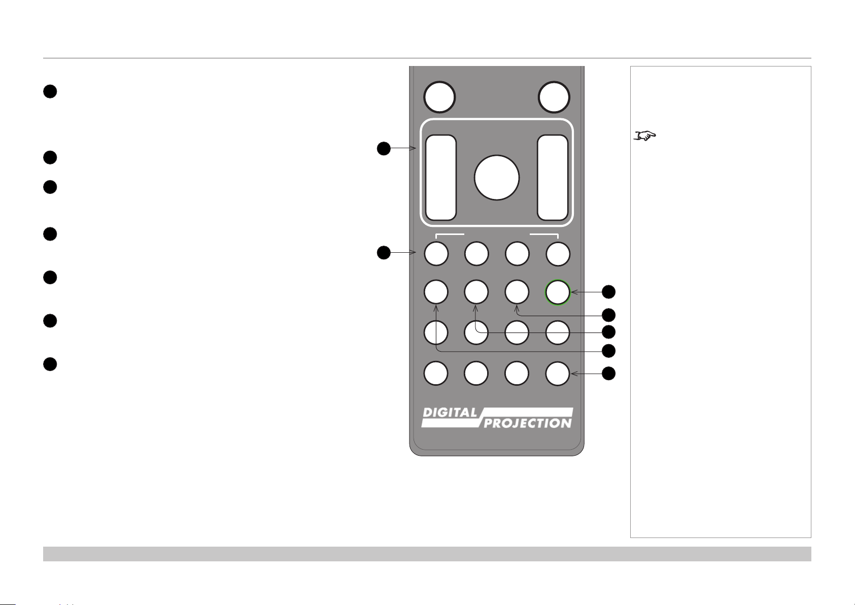
11
LENS adjustment
FOCUS IN / OUT: adjust focus.
SHIFT: press and hold this button, then use the Navigation arrow
buttons to move the lens.
ZOOM IN / OUT: adjust zoom.
12
USER PRESET A, B, C, D
Load user presets.
13
ALT
14
Press and hold this button to access alternative functions for all
buttons with a green label.
DVI / DisplayPort2 / numeric input 3
There is no DVI input on this projector.
Use with
15
HDMI 2 / HDMI 4 / numeric input 2
ALT to select the DisplayPort 2 input.
Select the HDMI 1 input.
Use with ALT to select the HDMI 4 input.
16
HDMI 1 / HDMI 3 / numeric input 1
Select the HDMI 1 input.
Use with ALT to select the HDMI 3 input.
17
TEST / SWAP / numeric input 0
Show a test pattern. Press again to show the next test pattern:
...Off, White, Black, Red, Green, Blue, CheckerBoard,
CrossHatch, V Burst, H Burst, ColorBar...
When PIP mode is on, use this button with ALT to swap the main and
sub images.
REMOTE CONTROL
FREEZE
FOCUS ZOOM
11
12
IN
OUT
A B C D
HDMI1
HDMI3
DisplayPort1
4 5 6
R G B ALL
VGA COMP1 COMP2
7 8 9 0
3D EYE PIP SWAP
LENS
SHIFT
USER PRESET
HDMI2 DVI
21 3
HDMI4
DisplayPort2
HD-T 3GSDI
RE-SYNC
IN
OUT
ALT
ALT
ADDR
TEST
Notes
This projector does not use the
following options on the remote:
HDMI 3 and HDMI 4
DVI, VGA, COMP 1 and COMP 2.
13
14
15
16
17
continues on next page...
Installation and Quick-Start Guide
Remote control
Rev C December 2017
page 9
Page 20
Pic Mute
OPEN
CLOSE
MENU
EXIT INFO
OK
LENS
FOCUS ZOOM
OSD
OFF
ON
DEFAULT
FREEZE
RE-SYNC
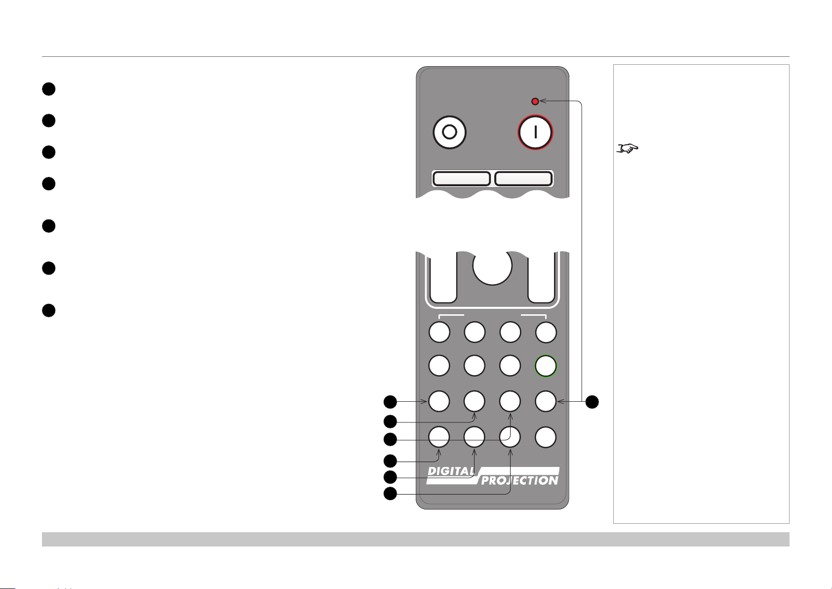
Digital Projection M-Vision Laser 18K Series
17
DISPLAYPORT 1 / R / numeric input 4
18
HD-T / G / numeric input 5
Select DisplayPort 1 input.
Select the HDBaseT input.
19
3GSDI / B / numeric input 6
Select the 3G-SDI input.
20
VGA / 3D / numeric input 7
There is no VGA input on this projector.
Use with ALT to toggle the 3D Format setting between Off and Auto.
21
COMP1 / EYE / numeric input 8
22
23
There is no Component 1 input on this projector.
Use with
ALT to switch between left and right eye 3D dominance.
COMP2 / PIP / numeric input 9
There is no Component 2 input on this projector.
Use with ALT to switch on Picture In Picture (PIP) mode.
ADDR / ALL (with red indicator at the top)
Assign and unassign an IR remote address.
To assign an address:
1. Press and hold this button until the indicator starts ashing.
2. Release this button and while the indicator is still ashing, enter
a two-digit address using the numeric input buttons. The indicator
will ash three times quickly to conrm the change.
To unassign an address and return to the default address 00,
• Press and hold ALT and this button simultaneously until the
indicator ashes to conrm the change.
REMOTE CONTROL
OFF ON
Remote control top
IN
OUT
A B C D
HDMI1
HDMI3
DisplayPort1
17
18
19
20
21
22
4 5 6
R G B ALL
VGA COMP1 COMP2
7 8 9 0
3D EYE PIP SWAP
Pic Mute
OPEN
SHIFT
USER PRESET
HDMI2 DVI
21 3
HDMI4
HD-T 3GSDI
CLOSE
OSD
DisplayPort2
Notes
This projector does not use the
following options on the remote:
HDMI 3 and HDMI 4
DVI, VGA, COMP 1 and COMP 2.
IN
OUT
ALT
ALT
ADDR
23
TEST
Installation and Quick-Start Guide
Remote control bottom
Rev C December 2017
page 10
Page 21
Digital Projection M-Vision Laser 18K Series
REMOTE CONTROL
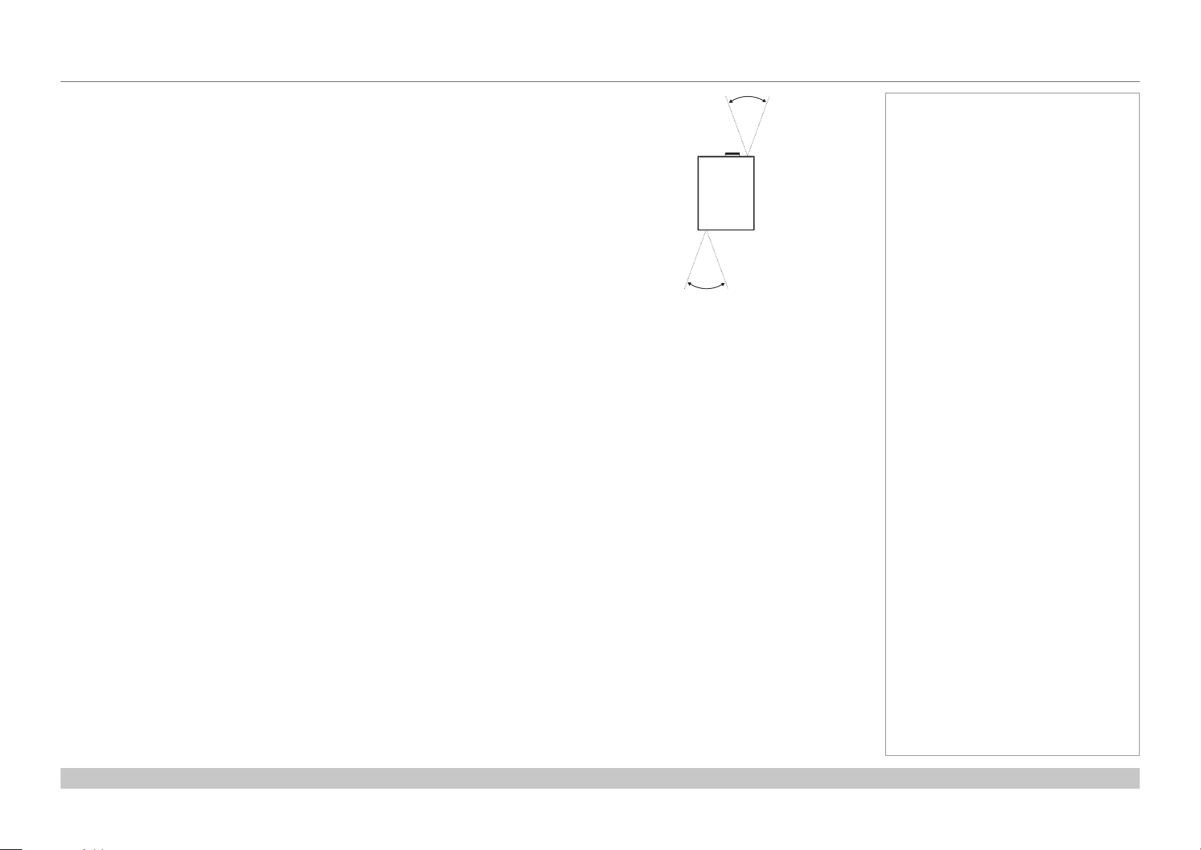
Infrared reception
The projector has infrared sensors at the front and back.
The angle of acceptance is 40°. Make sure that the remote control is within the angle of acceptance
when trying to control the projector.
40°
40°
Infrared reception
Notes
Installation and Quick-Start Guide
Rev C December 2017
page 11
Page 22
Digital Projection M-Vision Laser 18K Series
POSITIONING THE SCREEN AND PROJECTOR
Positioning The Screen And Projector
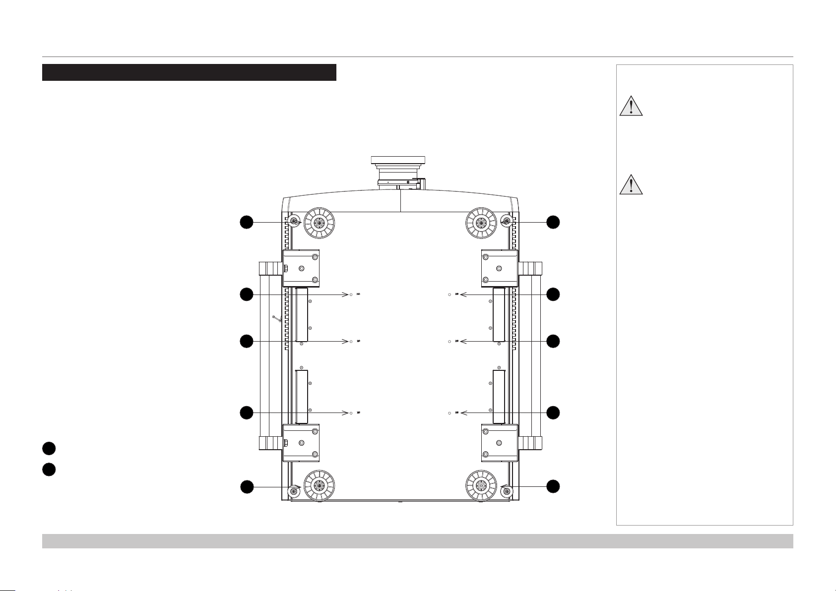
1. Install the screen, ensuring that it is in the best position for viewing by your audience.
2. Mount the projector, ensuring that it is at a suitable distance from the screen for the image to ll the screen. Set the adjustable feet so that
the projector is level, and perpendicular to the screen.
The drawing below shows the positions of the feet for table mounting, and the xing holes for ceiling mounting.
1
2
2
1
2
2
Notes
Always allow the projector
to cool for 5 minutes before
disconnecting the power or
moving the projector.
Ensure that there is at least 50
cm (19.7 in) of space between the
ventilation outlets and any wall,
and 30 cm (11.8 in) on all other
sides.
1
Four adjustable feet
2
Six M6 holes for ceiling mount
The screws should not penetrate
more than 15 mm into the body of
the projector.
Installation and Quick-Start Guide
2
1
2
1
Rev C December 2017
page 12
Page 23
Digital Projection M-Vision Laser 18K Series
POSITIONING THE SCREEN AND PROJECTOR
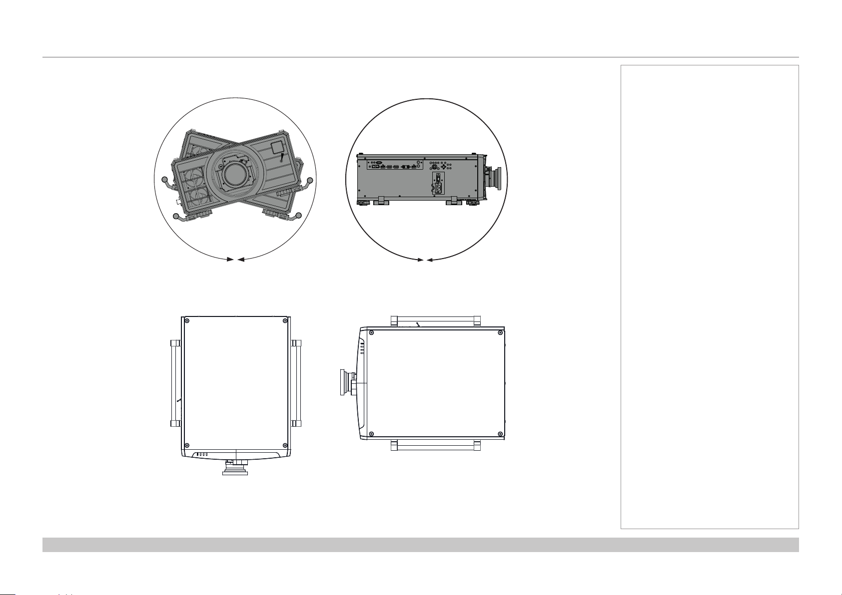
Roll and pitch
The projector can be operated in any position, as shown in the illustration.
360°
Roll
Fig. 1 Roll and pitch - any position is possible
However, the following positions are to be avoided as they can reduce motor life:
Notes
360°
Pitch
Installation and Quick-Start Guide
Lens facing down Inputs and outputs facing up
Fig. 2 Positions to avoid
Rev C December 2017
page 13
Page 24
Digital Projection M-Vision Laser 18K Series
POSITIONING THE SCREEN AND PROJECTOR
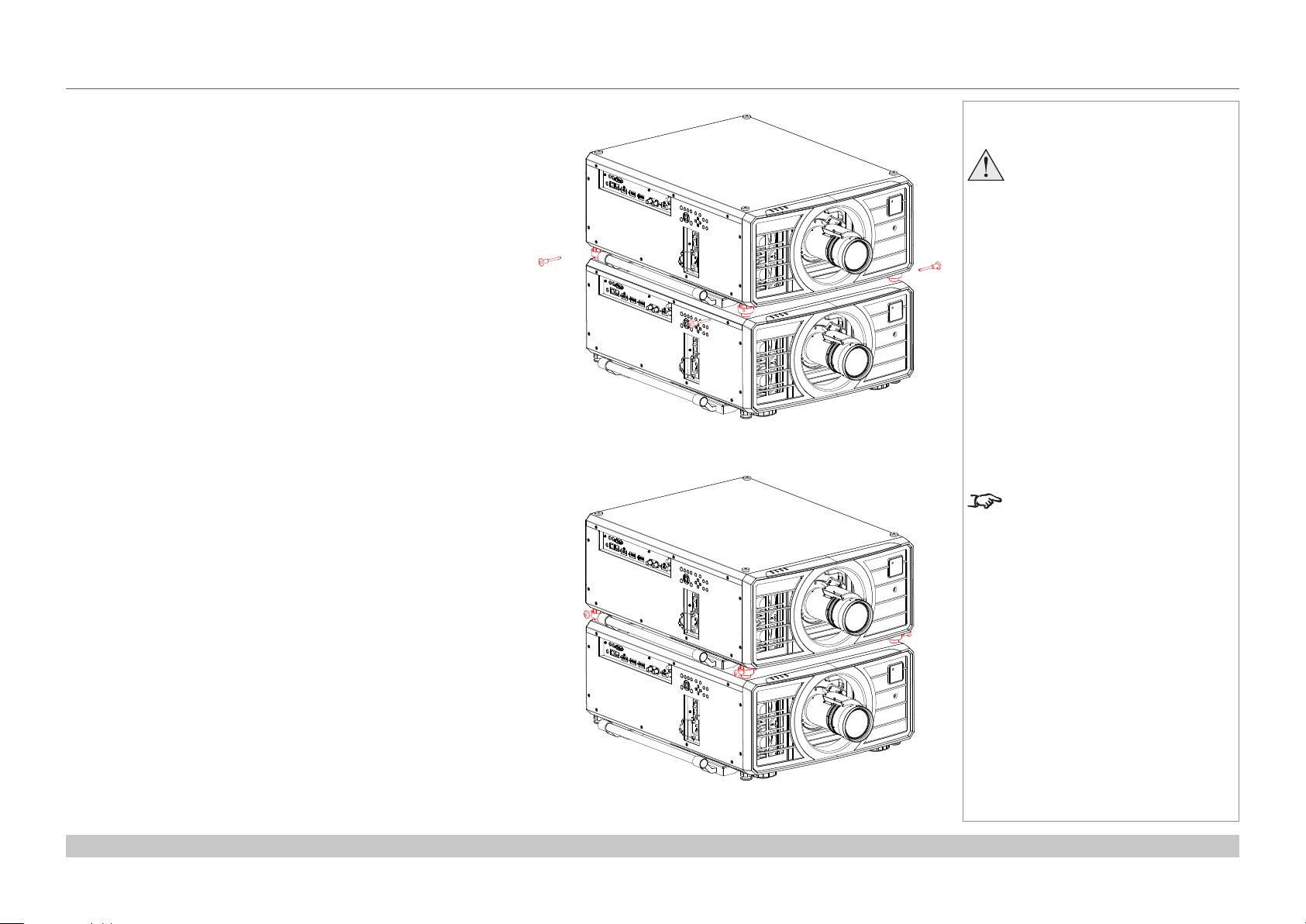
Stacking instructions
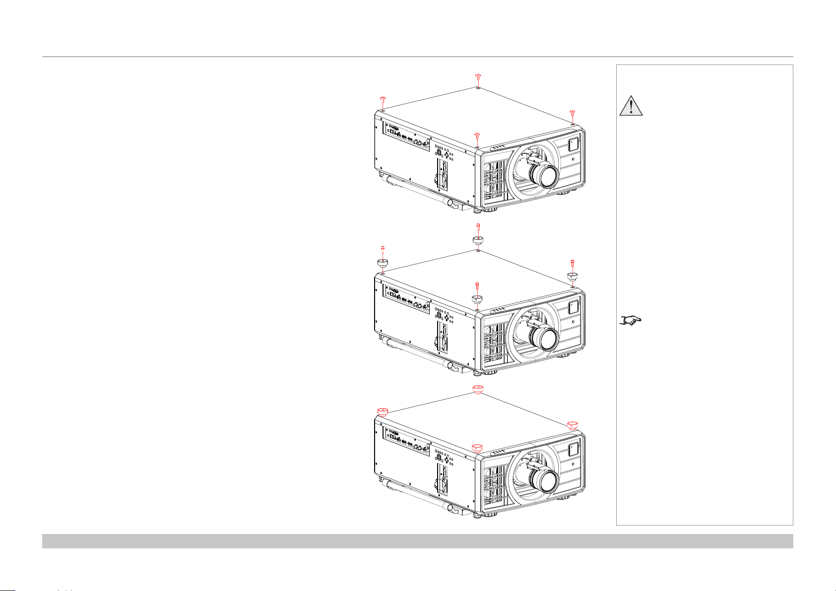
1. On the bottom projector, remove the four screws on the top side. Insert and
secure the stacking tops in their place.
Notes
When stacking projectors, the stack
MUST be vertical, to ensure that the
stresses are distributed to all four
chassis corners.
Do not stack more than two
projectors.
Do not use the provided eye bolts to
suspend more than one projector.
The eye bolts must not be used with
stacks as they can carry the weight of
one projector only.
Do not use the lifting handles when
stacking. The handles will carry the
weight of one projector only.
Use only the provided screws with
a torque of 25-30 kgf cm (2.45 - 2.94
Nm).
It is the customer’s responsibility to
ensure that the assembly is carried
out securely.
The stacking kit is provided in the
box as standard in some regions. It
is also available to order separately.
Installation and Quick-Start Guide
Rev C December 2017
page 14
Page 25
Digital Projection M-Vision Laser 18K Series
POSITIONING THE SCREEN AND PROJECTOR
Stacking instructions continued
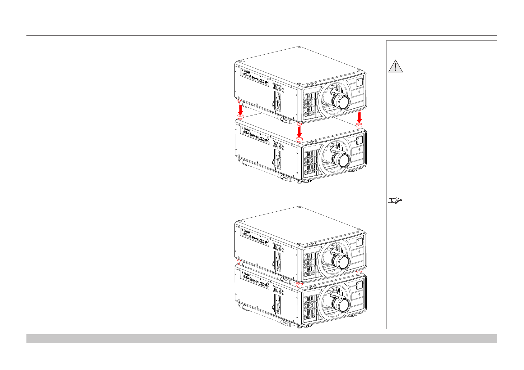
2. Remove the four adjustable feet of the top projector.
3. Slide the top projector over the bottom projector so the stacking feet are
coupled with the stacking tops on the bottom projector.
Notes
When stacking projectors, the stack
MUST be vertical, to ensure that the
stresses are distributed to all four
chassis corners.
Do not stack more than two
projectors.
Do not use the provided eye bolts to
suspend more than one projector.
The eye bolts must not be used with
stacks as they can carry the weight of
one projector only.
Do not use the lifting handles when
stacking. The handles will carry the
weight of one projector only.
Use only the provided screws with
a torque of 25-30 kgf cm (2.45 - 2.94
Nm).
It is the customer’s responsibility to
ensure that the assembly is carried
out securely.
The stacking kit is provided in the
box as standard in some regions. It
is also available to order separately.
Installation and Quick-Start Guide
Rev C December 2017
page 15
Page 26
Digital Projection M-Vision Laser 18K Series
POSITIONING THE SCREEN AND PROJECTOR
Stacking instructions continued
4. Use the provided holding pins to secure each connection.
Notes
When stacking projectors, the stack
MUST be vertical, to ensure that the
stresses are distributed to all four
chassis corners.
Do not stack more than two
projectors.
Do not use the provided eye bolts to
suspend more than one projector.
The eye bolts must not be used with
stacks as they can carry the weight of
one projector only.
Do not use the lifting handles when
stacking. The handles will carry the
weight of one projector only.
Use only the provided screws with
a torque of 25-30 kgf cm (2.45 - 2.94
Nm).
It is the customer’s responsibility to
ensure that the assembly is carried
out securely.
The stacking kit is provided in the
box as standard in some regions. It
is also available to order separately.
Installation and Quick-Start Guide
Rev C December 2017
page 16
Page 27
Digital Projection M-Vision Laser 18K Series
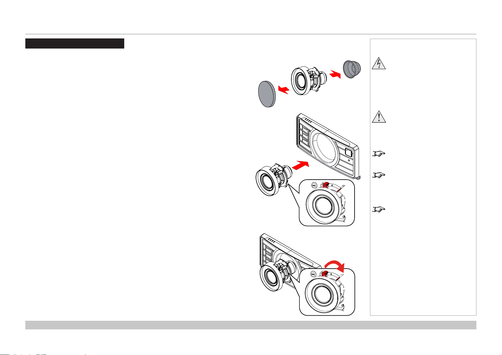
CHANGING THE LENS
Changing The Lens
Inserting a new lens
1. Remove the front and rear lens caps.
2. Insert the lens, keeping the connector in upright position.
Notes
Before changing the lens,
always make sure the projector
is switched off and fully
disconnected from its power
supply.
When changing the lens, avoid
using excessive force as this may
damage the equipment.
The lens is shipped separately.
Take care to preserve the original
lens packaging and protective caps
for future use.
The projector will not power on
without the lens tted.
3. Rotate the lens clockwise until it clicks into place.
Installation and Quick-Start Guide
Rev C December 2017
page 17
Page 28
Digital Projection M-Vision Laser 18K Series
CHANGING THE LENS
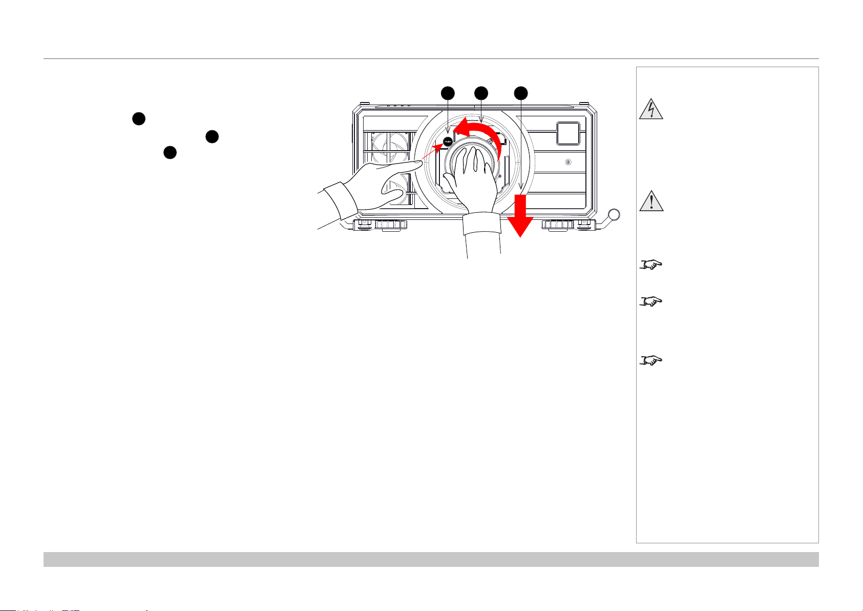
Removing the lens
1. Push the button 1 all the way in.
2. Rotate the lens counterclockwise 2 until it disengages.
3. Slowly pull the lens out 3.
Notes
1 32
Before changing the lens,
always make sure the projector
is switched off and fully
disconnected from its power
supply.
When changing the lens, avoid
using excessive force as this may
damage the equipment.
The lens is shipped separately.
Take care to preserve the original
lens packaging and protective caps
for future use.
The projector will not power on
without the lens tted.
Installation and Quick-Start Guide
Rev C December 2017
page 18
Page 29
Digital Projection M-Vision Laser 18K Series
OPERATING THE PROJECTOR
Operating The Projector
Switching the projector on
1. Ensure a lens is tted. Connect the power cable between the mains supply and the projector. (See Connecting the power supply
above.) Switch on at the switch next to the power connector.
2. The POWER indicator lights red to signal that the projector is in STANDBY mode. Press one of the following buttons:
• On the remote control, the ON button
• On the projector control panel, the POWER button.
The fans begin working, then the
both light steady green. The projector is switched on.
Switching the projector off
1. Press OFF on the remote control or POWER on the control panel, then press again to conrm your choice.
POWER indicator on the control panel will start ashing amber, the system will go out and the cooling fans will run for a short time
The
until the POWER indicator goes steady red to indicate that the projector has entered STANDBY mode.
2. If you need to switch the projector off completely, switch off at the mains power switch next to the power connector and then disconnect
the power cable from the projector.
POWER indicator begins ashing green. When the ashing stops, the POWER and LIGHT indicators
Notes
See also Connecting The Power
Supply earlier in this guide.
The self-test is running when all the
LEDs on the control panel are lit.
Use only the power cable
provided.
Ensure that the power outlet
includes a ground connection as
this equipment MUST be earthed.
Handle the power cable carefully
and avoid sharp bends. Do not
use a damaged power cable.
Installation and Quick-Start Guide
Rev C December 2017
page 19
Page 30
Digital Projection M-Vision Laser 18K Series
OPERATING THE PROJECTOR
Selecting an input signal
1. Connect one or more image sources to the projector.
2. Select the input you want to display:
• Press one of the input buttons on the remote control.
• Alternatively, open the On-screen display (OSD) by pressing MENU. Highlight Input from the main menu, press ENTER/OK and then
select an input signal using the UP and DOWN arrow buttons. Press ENTER/OK to conrm your choice.
Selecting a test pattern
To display a test pattern:
• Press TEST on the remote control.
Change the test pattern using the
White, Black, Red, Green, Blue, Checkerboard, CrossHatch, V Burst, H Burst, ColorBar, Aspect Ratios, Off
LEFT and RIGHT arrow buttons. Test patterns are displayed in the following order:
• Alternatively, open the OSD by pressing MENU. Highlight Test Patterns from the main menu, then select a test pattern using the LEFT
and RIGHT arrow buttons.
After the nal test pattern, the projector exits test pattern mode and returns to the main image. T
TEST again. If you wish to exit the test patterns before you reach the nal one,
o view test patterns again, you need to press
• press TEST or EXIT at any time.
Notes
For full details of how to use the
controls and the menu system, see
the Operating Guide.
Installation and Quick-Start Guide
Rev C December 2017
page 20
Page 31

Digital Projection M-Vision Laser 18K Series
OPERATING THE PROJECTOR
Adjusting the lens
The lens can be adjusted using the Lens menu, or using the lens buttons on the remote control.
Lens menu
The Lens menu provides access to the Lens Control setting and the Lens Center command.
Lens Control allows Zoom, Focus and Shift adjustment using the arrow buttons. The setting operates in Zoom/Focus Adjustment and
Shift Adjustment mode.
ENTER/SELECT to switch between the two modes.
Press
Remote control
Use the remote control to adjust zoom, focus and shift directly, without opening a menu:
• OK enters lens control, then switches between Zoom/Focus Adjustment and Shift Adjustment.
• EXIT exits lens control and opens the Lens menu.
• MENU exits lens control and returns to the main image.
• The arrow buttons adjust zoom, focus and shift as indicated on the screen.
Adjusting the image
Orientation
• This can be set from the Setup menu.
Highlight Orientation and choose from Front Tabletop, Front Ceiling, Rear Tabletop, Rear Ceiling and Auto-front.
Notes
For full details of how to adjust
the lens using the remote control,
see Remote Control earlier in this
guide.
Setup menu
Geometry
• Settings such as Keystone, Rotation, Pincushion / Barrel and Arc can be set from the Geometry menu.
Picture
• Settings such as Gamma, Brightness, Contrast, Saturation, Hue and Sharpness can be set from the Image menu.
Installation and Quick-Start Guide
Geometry menu
Image menu
Rev C December 2017
page 21
Page 32

Digital Projection M-Vision Laser 18K Series
This page is intentionally left blank.
Installation and Quick-Start Guide
Page 33

M-Vision Laser 18K Series
High Brightness Digital Video Projector
4
CONNECTION GUIDE
Rev C December 2017
Page 34

Digital Projection M-Vision Laser 18K Series
IN THIS GUIDE
IN THIS GUIDE
SIGNAL INPUTS AND OUTPUTS ................................................................25
Digital inputs and outputs ........................................................................................25
EDID on the DisplayPort, HDMI and HDBaseT inputs ...........................................26
Using DisplayPort/HDMI/HDBaseT switchers with the projector .........................26
3D connections .........................................................................................................27
Frame sequential 1080p and WUXGA 3D sources at 100 and 120 Hz ..........................27
Dual Pipe 1080p, WUXGA and WQXGA 3D sources at 100 and 120 Hz .......................27
3D Sync ......................................................................................................................28
3D Sync In ......................................................................................................................28
3D Sync Out ....................................................................................................................28
CONTROL CONNECTIONS
LAN connection examples .......................................................................................30
RS232 connection example .....................................................................................31
...........................................................................29
Connection Guide
Rev C December 2017
Page 35

Digital Projection M-Vision Laser 18K Series
SIGNAL INPUTS AND OUTPUTS
Signal Inputs and outputs
Digital inputs and outputs
HDBaseT
1
Receives digital signal from HDBaseT-compliant devices.
HDMI 1
2
HDMI 1.4a.
DisplayPort 1 / DisplayPort 2
3
DisplayPort 1.1a.
3G-SDI in / 3G-SDI out
4
From the 3G-SDI out port, connect a 3G-SDI cable to distribute the 3G-SDI signal to another projector.
HDMI 2
5
HDMI 1.4a.
Notes
For simultaneous HDBaseT and
LAN connectivity, a third-party
distribution product can be utilised
to combine HDBaseT video stream
with LAN connection for delivery to
the projector.
Connection Guide
3D SYNC - OUT
RS-2321 2TRIGGER
1
2 3
4 53
Rev C December 2017
page 25
Page 36

Digital Projection M-Vision Laser 18K Series
SIGNAL INPUTS AND OUTPUTS
EDID on the DisplayPort, HDMI and HDBaseT inputs
If you are using a computer graphics card or another source that obeys the EDID protocol, the source will automatically congure itself to suit
the projector.
Otherwise refer to the documentation supplied with the source to manually set the resolution to the DMD™ resolution of the projector or the
nearest suitable setting. Switch off the source, connect to the projector, then switch the source back on again.
Using DisplayPort/HDMI/HDBaseT switchers with the projector
When using a DisplayPort/HDMI/HDBaseT source switcher with the projector, it is important to set the switcher so that it passes the projector
EDID through to the source devices. If this is not done, the projector may not be able to lock to the source or display the source correctly as
its video output timings may not be compatible with those of the projector. Sometimes this is called transparent, pass-through or clone mode.
See your switcher’s manual for information on how to set this mode.
1
Sources
2
Switcher
3
Projector
1 32
EDID
EDID
EDID
EDID
Notes
Connection Guide
The EDIDs in the switcher should be the same as the one in the projector.
Rev C December 2017
page 26
Page 37

Digital Projection M-Vision Laser 18K Series
SIGNAL INPUTS AND OUTPUTS
3D connections
Frame sequential 1080p and WUXGA 3D sources at 100 and 120 Hz
1. Connect to a DisplayPort input.
2. Set 3D Format in the 3D menu to Frame Sequential.
Dual Pipe 1080p, WUXGA and WQXGA 3D sources at 100 and 120 Hz
1. Connect the left eye output to the HDMI 1 socket and the right eye output to the HDMI 2 socket.
2. Set 3D Format in the 3D menu to Dual-Pipe.
RS-2321 2TRIGGER
Notes
See 3D formats in the Reference
Guide for a complete list of
supported formats and frame rates.
While the projector can receive
100/120Hz and display 3D at
100/120Hz, video processing is
limited to 60Hz.
This also applies to Dual Pipe 3D at
60 Hz per input.
3D SYNC - OUT
1
HDMI 1 / Dual Pipe LEFT
2
DisplayPort 1
3
DisplayPort 2
4
HDMI 2 / Dual Pipe RIGHT
Connection Guide
1
2 3
4
Rev C December 2017
page 27
Page 38

Digital Projection M-Vision Laser 18K Series
SIGNAL INPUTS AND OUTPUTS
3D Sync
3D Sync In
Sync input signal. Connect the 3D sync from your graphics card or server.
3D Sync Out
Sync output signal. This may be affected by the
Connect this to your IR emitter or ZScreen.
RS-2321 2TRIGGER
Sync Offset setting in the 3D Control menu.
3D SYNC - OUT
1
2
1
2
3D Sync IN
3D Sync OUT
Notes
Connection Guide
3 4 5
3
3D input
4
3D Sync In
5
3D Sync OUT
6
6
IR emitter or ZScreen
Rev C December 2017
page 28
Page 39

Digital Projection M-Vision Laser 18K Series
CONTROL CONNECTIONS
Control Connections
1
2
3
4
5
6
Trigger 1
Trigger 2
The Trigger outputs are activated by one of the three following conditions, as set in the Setup menu:
• Screen trigger: can be connected to an electrically operated screen, automatically deploying the screen when the projector
starts up, and retracting the screen when the projector shuts down.
• Aspect ratio trigger: can be used to control screen shuttering for different aspect ratios.
• RS232 trigger: can be used to control the screen or screen shuttering on receipt of an RS232 command
RS232
• All of the projector’s features can be controlled via a serial connection, using commands described in the Protocol Guide.
• Use a straight-through cable to connect directly to a computer.
Wired Remote
The remote control can be connected using a standard 3.5 mm mini jack cable (tip-ring-sleeve, or TRS).
LAN
This dedicated LAN connection can be used if HDBaseT/LAN is already being used for HDBaseT signal input.
HDBaseT/LAN
The projector’s features can be controlled via a LAN connection, using Digital Projection’s Projector Controller application or a
terminal-emulation program.
1 2 3
Notes
For a list of all commands used to
control the projector via LAN, see
the Protocol Guide.
Only one remote connection (RS232
or LAN) should be used at any one
time.
With a LAN connection the projector
can serve a web page offering basic
projector controls.
Trigger 1 and Trigger 2 are not
available with HDMI 3 and 4 inputs.
Projector Controller is available for
download, free of charge, from the
Digital Projection website.
4
Connection Guide
3D SYNC - OUT
RS-2321 2TRIGGER
5 6
Rev C December 2017
page 29
Page 40

Digital Projection M-Vision Laser 18K Series
3D SYNC - OUT
CONTROL CONNECTIONS
LAN connection examples
The projector’s features can be controlled via a LAN connection, using Digital Projection’s Projector Controller application or a terminalemulation program
Un-crossed
LAN cable
Computer
Un-crossed LAN cables
Projector
Computer
Notes
With a LAN connection the projector
can serve a web page offering basic
projector controls.
Projector Controller is available for
download, free of charge, from the
Digital Projection website.
For simultaneous HDBaseT and
LAN connectivity, a third-party
distribution product can be utilised
to combine HDBaseT video stream
with LAN connection for delivery to
the projector.
Hub or LAN
Connection Guide
Projector
Projector
1
LAN
2
HDBaseT/LAN
RS-2321 2TRIGGER
1 2
Rev C December 2017
page 30
Page 41

Digital Projection M-Vision Laser 18K Series
3D SYNC - OUT
CONTROL CONNECTIONS
RS232 connection example
All of the projector’s features can be controlled via a serial connection, using commands described in the Protocol Guide.
Straight-
through cable
Computer
Projector
Notes
The Protocol Guide is available
separately.
1
Connection Guide
1
RS-2321 2TRIGGER
RS-232
Rev C December 2017
page 31
Page 42

Digital Projection M-Vision Laser 18K Series
This page is intentionally left blank.
Connection Guide
Page 43

M-Vision Laser 18K Series
High Brightness Digital Video Projector
4
OPERATING GUIDE
Rev C December 2017
Page 44

Digital Projection M-Vision Laser 18K Series
CONTENTS
CONTENTS
USING THE MENUS ................................................................................35
OPENING THE OSD
OPENING A MENU
EXITING MENUS AND CLOSING THE OSD
INSIDE A MENU
Accessing sub-menus
Executing commands
EDITING PROJECTOR SETTINGS
Using a slider to set a value
Editing numeric values
..................................................................... 35
....................................................................... 35
.................................. 35
........................................................................... 36
......................................................................... 36
.......................................................................... 36
................................................ 37
................................................................ 37
........................................................................ 37
USING THE PROJECTOR ....................................................................38
MAIN MENU
LENS MENU
Lens Control
Lens Memory
IMAGE MENU
COLOR MENU.............................................................................. 42
Color Space
Color Mode.......................................................................................... 43
GEOMETRY MENU
Aspect Ratio
Digital Zoom
Overscan
Blanking
Keystone
Operating Guide
................................................................................. 38
................................................................................. 39
........................................................................................ 39
...................................................................................... 40
............................................................................... 41
........................................................................................ 42
....................................................................... 48
........................................................................................ 48
........................................................................................ 50
............................................................................................. 51
.............................................................................................. 52
............................................................................................. 53
4 Corners
Rotation
Pincushion / Barrel
Arc
Custom Warp
EDGE BLEND MENU
Blend Width
Black Level Uplift................................................................................. 61
3D MENU
3D types
Some 3D settings explained
LASER MENU
SETUP MENU
ColorMax Setting................................................................................. 69
Power On/Off
Clock Adjust
OSD Settings
Memory
NETWORK MENU
PIP MENU
INFORMATION MENU
Signal Format
System Status
Thermal Status
Factory Reset
............................................................................................ 55
............................................................................................... 56
.............................................................................. 57
....................................................................................................... 58
...................................................................................... 58
.................................................................... 59
......................................................................................... 60
..................................................................................... 62
.............................................................................................. 63
............................................................... 65
.............................................................................. 66
.............................................................................. 67
...................................................................................... 70
........................................................................................ 71
...................................................................................... 72
............................................................................................... 72
........................................................................ 73
.................................................................................... 74
.................................................................. 75
...................................................................................... 75
..................................................................................... 76
.................................................................................... 76
...................................................................................... 77
Rev C December 2017
Page 45

Digital Projection M-Vision Laser 18K Series
FREEZE
RE-SYNC
USING THE MENUS
Using The Menus
Opening the OSD
Access the various menus using
either the projector control panel or
the remote control. On either device,
• press the MENU button.
The on-screen display (OSD) opens
showing the list of available menus.
Opening a menu
Move up and down the list using the
UP and DOWN arrow buttons.
To open a menu,
• press ENTER on the control
panel or
control.
This guide refers to the above two
buttons as
Exiting menus and
closing the OSD
To go back to the previous page,
• press EXIT.
When you reach the top level,
pressing
To close the OSD from any page,
• press MENU.
OK on the remote
ENTER/OK.
EXIT will close the OSD.
POWER
Input
Test Pattern
Lens
Image
Color
Geometry
Edge Blend
3D
Laser
Setup
Network
INPUT
AUTO
SYNC
ASPECT
CENTER
LENS
PIC MUTE
Projector control panel
Main Menu
HDMI 1
PIP
u
u
u
u
u
u
u
u
u
q
Information
On-screen display (OSD): top level menus
OFF ON
MENU
EXIT INFO
Remote control
Main Menu
p
OFF
OFF
Notes
Pic Mute
ON
OSD
ON
DEFAULT
OK
u
u
Operating Guide
Rev C December 2017
page 35
Page 46

Digital Projection M-Vision Laser 18K Series
USING THE MENUS
Inside a menu
When you open a menu, the page consists of the following elements:
• Title bar at the top
Shows which menu you have accessed.
• Highlighted item
• Available and unavailable items
Unavailable items appear a pale gray color. Whether an item is available may depend
on other settings.
• The text or symbol to the right of an item shows whether the item:
• has a value that can be changed (the current value is shown)
• opens a sub-menu (an arrow button is displayed)
• executes a command (the space to the right of the item is blank).
Accessing sub-menus
Use the
ENTER/OK.
Executing commands
If the item contains a command, highlighting it reveals an
Press
UP and DOWN arrow buttons to highlight the sub-menu, then press
OK button.
ENTER/OK to execute the highlighted command.
Menu Name
Highlighted Item
Menu Item
Unavailable Item
Slider
Sub-menu
Command
Value
Value
Value
Value
Inside a menu
Menu Name
Menu Item Value
Highlighted Command
Notes
The highlighted item has green
background.
u
OK
You may be asked for conrmation. Use the
Operating Guide
ENTER/OK to conrm, or EXIT to cancel.
Highlighted command
Command Name
WARNING
All [Menu] values will be lost.
Press OK to confirm
Press Exit to cancel
Conrmation dialog
Rev C December 2017
page 36
Page 47

Digital Projection M-Vision Laser 18K Series
USING THE MENUS
Editing projector settings
If the highlighted menu item contains a list of values to choose from, you can change the
value by doing the following:
1. Highlight the menu item and press ENTER/OK.
2. In the list of values that opens, use the UP and DOWN arrow buttons to
highlight a value, then press ENTER/OK again to select the highlighted value.
Using a slider to set a value
Some parameters open a slider. To set such a parameter:
1. Press the LEFT or RIGHT arrow button, or ENTER/OK.
The arrow buttons will open the slider and adjust the value at the same time.
ENTER/OK will open the slider without altering the initial value.
2. Use the LEFT and RIGHT arrow buttons to move the slider.
3. When ready, press EXIT to exit the slider and return to the menu, or press MENU to
exit the slider without showing the menu again.
Editing numeric values
Some parameters take numeric values without using sliders - for example, color matching
values or IP addresses.
1. Use the UP and DOWN arrow buttons to highlight the row containing the
numeric eld you wish to edit.
2. Press ENTER/OK to enter edit mode. A numeric eld in edit mode is white text on
blue background.
3. In edit mode:
• Use the UP arrow button to increase the numeric value.
• Use the DOWN arrow button to decrease the numeric value.
4. Use the LEFT and RIGHT arrow buttons to edit the next or previous numeric
elds within the same row.
5. Once ready, press ENTER/OK to exit edit mode.
Menu Name
Highlighted Item Current Value
Menu Item
Menu Item
Highlighted Value
Value
Value
Value
List of values
Parameter
Value
Slider
Data
Row
Highlighted Row
Row
Row x: 0.276 y: 0.283
x: 0.658 y: 0.339
x: 0.315 y: 0.662
x: 0.146 y: 0.043
Numeric values
Notes
Some menu items may be
unavailable due to settings in other
menus. Unavailable menu items
appear gray.
Operating Guide
Rev C December 2017
page 37
Page 48

Digital Projection M-Vision Laser 18K Series
USING THE PROJECTOR
Using The Projector
Main menu
• Input
ENTER/OK to open the list of available inputs.
Press
Use the
ENTER/OK to conrm your choice.
Press
• Test Pattern
Choose from:
...Off, White, Black, Red, Green, Blue, Cyan, Yellow, Magenta...
Use the
• Lens, Image, Color, Geometry, Edge Blend, 3D, Laser, Setup and Network
Press ENTER/OK to open these menus and access various settings.
Press the
• PIP and Information
Press ENTER/OK to open these menus and access various settings.
Press the
UP and DOWN arrow buttons to select an input from the list, then press
EXIT to return to the main menu.
LEFT and RIGHT arrow buttons to switch between values.
DOWN arrow at the bottom of the page to access additional menus:
UP arrow to return to the previous page.
Input
Test Pattern
Lens
Image
Color
Geometry
Edge Blend
3D
Laser
Setup
Network
PIP
Information
Main Menu
q
Main Menu
p
HDMI 1
Notes
See Signal Inputs in the
u
u
u
u
u
u
u
u
u
u
u
Connection Guide for further
information about the available
inputs and connections.
Selecting a test pattern hides the
OSD. Press EXIT to hide the test
pattern, and then press MENU to
show the OSD.
Operating Guide
Main menu, page 1 and 2
Rev C December 2017
page 38
Page 49

Digital Projection M-Vision Laser 18K Series
USING THE PROJECTOR
Lens menu
• Lens Lock
When this feature is On, all other Lens menu items are disabled.
• Lens Control
Opens a sub-menu, see below.
• Center Lens
Centers the lens.
• Lens Memory
Opens a sub-menu, see next page.
Lens Control
Lens Control settings operate in Zoom/Focus Adjustment and Shift Adjustment
mode. Press
When in
ENTER/OK to switch between modes.
Zoom/Focus Adjustment mode:
• Use the UP and DOWN arrow buttons to adjust Zoom.
• Use the LEFT and RIGHT arrow buttons to adjust Focus.
Lens
Lens Lock
Lens Control
Center Lens
Lens Memory
Lens Control
Zoom
Focus
[Enter] Shift Adjustment
p
t
Notes
Off
u
u
q
u
When in
Shift Adjustment mode, use the arrow buttons to adjust Shift.
Operating Guide
Lens Control
p
Shift
t
q
[Enter] Zoom / Focus Adjustment
u
Rev C December 2017
page 39
Page 50

Digital Projection M-Vision Laser 18K Series
USING THE PROJECTOR
Lens menu continued from previous page
Lens Memory
This menu allows you to load, save and delete up to ten lens presets, containing position,
zoom, focus and shift adjustment information.
For example, if using different screen sizes and aspect ratios, you can save zoom, focus
and positioning for each screen size and aspect ratio in a dedicated preset.
Use
Clear Memory to delete a memory preset if you need to save a new combination of
lens settings in its place. Overwriting a saved memory preset is not possible.
Memory 1
Memory 2
Memory 3
Memory 4
Memory 5
Memory 6
Memory 7
Memory 8
Memory 9
Memory 10
Lens Load Memory
OK
Memory 1
Memory 2
Memory 3
Memory 4
Memory 5
Memory 6
Memory 7
Memory 8
Memory 9
Memory 10
Lens Save Memory
OK
Load Memory
Save Memory
Clear Memory
Lens Clear Memory
Memory 1
Memory 2
Memory 3
Memory 4
Memory 5
Memory 6
Memory 7
Memory 8
Memory 9
Memory 10
Notes
Lens Memory
u
u
u
OK
Operating Guide
Rev C December 2017
page 40
Page 51

Digital Projection M-Vision Laser 18K Series
Brightness
100
USING THE PROJECTOR
Image menu
• Picture Mode
Choose from High Bright, Presentation and Video.
Use a different setting depending the type of input source.
Press ENTER/SELECT to open the list.
Use the UP and DOWN arrow buttons to select a picture mode from the list, then
press ENTER/OK to conrm your choice.
Press EXIT to return to the main menu.
• Dynamic Black
Set to On to allow for increased contrast in darker scenes by modulating the light
source.
• Light Off Timer
When Dynamic Black is On, the Laser light source may turn off depending upon the
setting of the Light Off Timer. Options are: Disable, 0.5, 1.0, 1.5, 2.0, 3.0, 4.0
seconds.
• Gamma
Choose a de-gamma curve from 1.0, 1.8, 2.0, 2.2, 2.35, 2.5, S-Curve and DICOM.
Used correctly, the Gamma setting can improve contrast while maintaining good
details for blacks and whites.
If excess ambient light washes out the image and it is difcult to see details in dark
areas, lower the Gamma setting to compensate. This improves contrast while
maintaining good details for blacks. Conversely, if the image is washed out and
unnatural, with excessive detail in black areas, increase the setting.
S-Curve is an enhanced mid-tone gamma.
DICOM is a simulated DICOM display, which can be used for training applications.
• Brightness, Contrast, Saturation, Hue, Sharpness, Noise Reduction
Highlight the setting you wish to edit, and then press ENTER/OK, or the LEFT or
RIGHT arrow button to open the slider.
Use the LEFT and RIGHT arrow buttons to adjust the slider.
Press EXIT to close the slider and return to the menu, or MENU to close the slider
and return to the projected image.
• Freeze
Freezes the current frame.
• Resync
Press ENTER/OK to force the projector to resynchronise with the current input.
Image
Picture Mode
Dynamic Black
Light Off Timer ----
Gamma
Brightness
Contrast
Saturation
Hue
Sharpness
Noise Reduction
Freeze
Resync
High Bright
Off
2.2
100
100
100
100
10
Off
Notes
Operating Guide
Rev C December 2017
page 41
Page 52

Digital Projection M-Vision Laser 18K Series
USING THE PROJECTOR
Color menu
Color Space
In most cases, the
you can choose a specic colorspace:
Choose from
Auto setting determines the correct colorspace to use. If it does not,
Auto, YPbPr, YCbCr, RGB PC and RGB Video.
Color
Color Space
Color Mode
ColorMax
Manual Color Matching
Color Temperature
Gains and Lifts
Color
Color Space
Color Mode
ColorMax
Manual Color Matching
Color Temperature
Gains and Lifts
Auto
ColorMax
Peak
Native
Auto
Native
ColorMax
Auto
Auto
Peak
YPbPr
100
YCbCr
Native
100
RGB PC
100
RGB Video
Notes
u
u
u
u
Operating Guide
Rev C December 2017
page 42
Page 53

Digital Projection M-Vision Laser 18K Series
USING THE PROJECTOR
Color Mode
The projector can work in the following color modes:
Color Temperature and Gains and Lifts.
ColorMax
ColorMax, Manual Color Matching,
1. Set Color Mode to ColorMax.
2. Navigate to the ColorMax setting. Choose from HDTV, Peak, User 1 and User 2.
User 1 and User 2 are user-dened color gamuts set via the Setup > ColorMax menu.
Color
Color Space
Color Mode
ColorMax
Manual Color Matching
Color Temperature
Gains and Lifts
Color
Color Space
Color Mode
ColorMax
Manual Color Matching
Color Temperature
Gains and Lifts
Auto
ColorMax
ColorMax
Manual Color Matching
Color Temperature
Gains and Lifts
Auto
ColorMax
Peak
HDTV
Peak
User 1
User 2
Notes
Only one color mode can be
selected at a time. Settings used by
the other color modes are disabled.
See Setup menu for further
information about setting up the
User 1 and User 2 color gamuts.
Operating Guide
Rev C December 2017
page 43
Page 54

Digital Projection M-Vision Laser 18K Series
USING THE PROJECTOR
Color menu continued from previous page
Manual Color Matching
1. Set Color Mode to Manual Color
Matching.
2. Open the Manual Color Matching
submenu.
Here you can do the following:
• Switch Auto Test Pattern On
and Off.
• Adjust Hue, Saturation
Gain settings for each
and
individual color to improve the
color balance of the projected
image.
• Adjust white balance RGB
values.
• Reset all values.
Manual Color Matching — Red
Hue
Saturation
Gain
100
100
100
Manual Color Matching
Auto Test Pattern
Red
Green
Blue
Yellow
Cyan
Magenta
White Balance
Reset
Off
Manual Color Matching — White
Red
Green
Blue
100
100
100
Notes
u
u
u
u
u
u
u
For more details about the Hue,
Saturation and Gain settings,
see Color matching parameters
explained further in this guide.
Operating Guide
Rev C December 2017
page 44
Page 55

Digital Projection M-Vision Laser 18K Series
USING THE PROJECTOR
Color menu continued from previous page
Color matching parameters explained
The levels of hue, saturation and gain in the
Manual Color Matching menu change the
color values in the following ways:
1
Hue
Species the position of each color
(red, yellow, green, cyan, blue and
magenta) relative to its neighboring
colors.
2
Saturation
Species the level of white in each
color (i.e. how “pale” each color is).
3
Gain
Controls the amount of light that goes
into each color, i.e. the lowest gain
would produce black.
MAGENTA
RED
WHITE
CYAN
1
YELLOW
GREENBLUE
Notes
2
RED
BLACK
3
Operating Guide
Rev C December 2017
page 45
Page 56

Digital Projection M-Vision Laser 18K Series
USING THE PROJECTOR
Color menu continued from previous page
Color Temperature
1. Set Color Mode to Color Temperature.
2. Navigate to the Color Temperature setting. Choose a value from 3200K (warmer)
to 9300K (cooler) or Native (no correction).
Color
Color Space
Color Mode
ColorMax
Manual Color Matching
Color Temperature
Gains and Lifts
Auto
Color Temperature
Peak
u
Native
3200K
5400K
6500K
7500K
9300K
Native
u
Notes
Operating Guide
Rev C December 2017
page 46
Page 57

Digital Projection M-Vision Laser 18K Series
USING THE PROJECTOR
Color menu continued from previous page
Gains and Lifts
Lifts allow you to adjust black levels of individual colors, while gains adjust the bright part
of the scale.
Set the sliders as required.
Red Lift
Green Lift
Blue Lift
Red Gain
Green Gain
Blue Gain
Reset
Notes
Gains and Lifts
100
100
100
100
100
100
Operating Guide
Rev C December 2017
page 47
Page 58

Digital Projection M-Vision Laser 18K Series
USING THE PROJECTOR
Geometry menu
This menu allows you to compensate for image distortions caused by an unusual projection
angle or irregular screen surface.
Aspect Ratio
This feature denes the aspect ratio of the source. Use the
If you choose a preset aspect ratio from here, it will give you the best t for your selection.
Choose from:
Setup > Screen Setting to dene the screen aspect ratio.
• 5:4
• 4:3
• 16:10
• 16:9
• 1.88
• 2.35
• TheaterScope
• Source
• Unscaled
Geometry
Aspect Ratio
Digital Zoom
Overscan
Blanking
Keystone
4 Corners
Rotation
Pincushion / Barrel
Arc
Custom Warp
Source
Off
Off
Notes
u
u
u
u
u
u
u
Only one of the following should be
used at any one time. Keystone,
4 Corners, Rotation,
Pincushion/Barrel and Arc
For more complex adjustments use
Custom Warp later in this section.
Image scaling and aspect ratio are
also inuenced by Setup > Screen
Setting
See next page for further information
about the TheaterScope aspect
ratio.
.
Operating Guide
Rev C December 2017
page 48
Page 59

Digital Projection M-Vision Laser 18K Series
Black margin – part of the source
Black margin – part of the source
USING THE PROJECTOR
Theaterscope setting
The TheaterScope setting is used in combination with an anamorphic lens to restore 2.35:1 images packed into a 16:9 frame. Such images
are projected with black lines at the top and bottom of the 16:9 screen to make up for the difference in aspect ratios.
Without an anamorphic lens and without the TheaterScope setting applied, a 16:9 source containing a 2.35:1 image looks like this:
If we change the setting to
the DMD™:
TheaterScope, the black lines will disappear but the image will stretch vertically to reach the top and bottom of
Notes
TheaterScope is used with an
anamorphic lens.
If you use TheaterScope, set the
screen aspect ratio to 16:9.
An anamorphic lens will stretch the image horizontally, restoring the original 2.35 ratio:
Operating Guide
Rev C December 2017
page 49
Page 60

Digital Projection M-Vision Laser 18K Series
Digital Zoom
USING THE PROJECTOR
.Geometry menu continued from previous page
Digital Zoom
Digital zooming enlarges a section of the image, while the area outside the enlarged
section is cropped out to preserve the overall image size.
• Digital Zoom denes the level of zoom that needs to be applied. If Digital Zoom is
set to 0, then the other settings in the menu will be disabled.
• Digital Pan and Digital Scan specify the area that is being enlarged:
• Digital Pan adjusts the horizontal coordinates.
• Digital Scan adjusts the vertical coordinates.
Reset command restores the default Digital Zoom, Digital Pan and Digital Scan
The
values.
Digital Zoom
Digital Pan
Digital Scan
Reset
Notes
0
0
0
Operating Guide
Rev C December 2017
page 50
Page 61

Digital Projection M-Vision Laser 18K Series
USING THE PROJECTOR
Geometry menu continued from previous page
Overscan
Use this setting to compensate for noisy or badly dened image edges.
Crop removes unwanted artifacts from the edges of your image by cropping the edges.
Zoom increases the size of the image to force the edges off-screen.
Geometry
Aspect Ratio
Digital Zoom
Overscan
Blanking
Keystone
4 Corners
Rotation
Pincushion / Barrel
Arc
Source
Off
Off
Crop
Zoom
Notes
u
u
u
u
u
u
u
Operating Guide
Image with noisy edges Overscanned image
Rev C December 2017
page 51
Page 62

Digital Projection M-Vision Laser 18K Series
USING THE PROJECTOR
Geometry menu continued from previous page
Blanking
Use this feature to:
• t an odd-sized screen;
• cut off timecode dots in the top line of a picture;
• cut off subtitles, etc.
Select the edge you wish to blank and use the
determine the amount of correction.
Use the
Reset command to restore blanked edges.
LEFT and RIGHT arrow buttons to
Top
Bottom
Left
Right
Reset
Notes
Blanking
0
0
0
0
Operating Guide
Rev C December 2017
page 52
Page 63

Digital Projection M-Vision Laser 18K Series
USING THE PROJECTOR
Geometry menu continued from previous page
Keystone
Use this setting to compensate for any distortion caused by the projector being in a
different horizontal or vertical plane to the screen.
Keystone example
1
The projector is positioned at an angle
2
The resulting image is distorted
3
The image is corrected when Keystone is applied
H Keystone
V Keystone
Rotation
Reset
Notes
Keystone
0
0
0
Operating Guide
21 3
Rev C December 2017
page 53
Page 64

Digital Projection M-Vision Laser 18K Series
USING THE PROJECTOR
Geometry menu continued from previous page
Keystone settings
1
Projector to the left
The projector is positioned
to the left of the screen.
To correct, apply a positive
Horizontal Keystone
value using the RIGHT
arrow button.
2
Projector to the right
The projector is positioned
to the right of the screen.
To correct, apply a negative
Horizontal Keystone
value using the LEFT arrow
button.
3
Projector high
The projector is positioned
above the screen at a
downward angle.
To correct, apply a negative
Vertical Keystone value
using the DOWN arrow
button.
Notes
1
2
4
Projector low
The projector is positioned
below the screen at an
upward angle.
To correct, apply a positive
Vertical Keystone value
using the UP arrow button.
5
Projector straight
The projector is directly
opposite the screen at a
right angle both horizontally
and vertically.
No correction is needed.
Operating Guide
4
53
Horizontal and vertical keystone corrections
Rev C December 2017
page 54
Page 65

Digital Projection M-Vision Laser 18K Series
USING THE PROJECTOR
Geometry menu continued from previous page
4 Corners
For each corner, apply horizontal and / or vertical correction as necessary to restore the
rectangular shape of the image.
Top Right Corner example
In this illustration, the top right corner requires both horizontal and vertical correction.
4 Corners
Top Left Corner
Top Right Corner
Bottom Left Corner
Bottom Right Corner
Reset
Top Right Corner Adjustment
Top Right Corner x
Top Right Corner y
t
p
Notes
u
u
u
u
0
u
0
q
Corner corrections provide a simple
setup for awkward installations and
irregular shaped screens that may
distort the image. To apply a similar
(but less exible) correction, while
preserving the original aspect ratio
of the image, use the Keystone
menu.
Operating Guide
Top Right Corner correction
Rev C December 2017
page 55
Page 66

Digital Projection M-Vision Laser 18K Series
USING THE PROJECTOR
Geometry menu continued from previous page
Rotation
Use this feature for example to correct a mounting error causing the image not to be level
with the screen.
Rotation example
1
DMD™ area
The DMD™ is not rotated. It still covers the area that would be occupied by the
image without correction.
2
Rotated image
The image is smaller than the surrounding DMD™ area. It is scaled in order to
remain within the DMD™ area.
3
Angle of rotation
The angle equals a quarter of the Rotation setting.
In this example the angle is 5°, therefore
1
Rotation = 20.
Rotation
Reset
Notes
Rotation
0
2
Operating Guide
3
Rev C December 2017
page 56
Page 67

Digital Projection M-Vision Laser 18K Series
USING THE PROJECTOR
Geometry menu continued from previous page
Pincushion / Barrel
Pincushion or barrel distortions are the result of poor or incorrect tensioning of the screen
or using a surface that is not at.
Use the
Pincushion / Barrel control to compensate electronically for such distortions.
You can also use this menu to make simple panoramic screen corrections without using
external processors.
Pincushion / Barrel example
H Pin/Barrel
V Pin/Barrel
Keystone
Reset
Pincushion / Barrel
The illustration shows pincushion and barrel correction applied both horizontally and vertically, in equal measures.
Notes
0
0
u
Operating Guide
Pincushion Barrel
Rev C December 2017
page 57
Page 68

Digital Projection M-Vision Laser 18K Series
USING THE PROJECTOR
Geometry menu continued from previous page
Arc
This feature is similar to
Pincushion / Barrel but allows you to apply curvature to each
edge of the image independently so you can have any combination of corrections.
Custom Warp
Settings User 1 and User 2 are selections of user created predownloaded custom warp maps.
Top
Bottom
Left
Right
Reset
Geometry
Aspect Ratio
Digital Zoom & Shift
Overscan
Blanking
Keystone
4 Corners
Rotation
Pincushion / Barrel
Custom Warp
Arc
0
0
0
0
Source
Off
Off
User 1
User 2
Notes
Please note that a positive Arc
value on any edge will reduce the
image size as the projector needs to
maintain the aspect ratio.
A negative Arc value will not affect
the overall image size.
Custom warp maps may be created
using the Digital Projection -
u
u
u
u
u
u
Projector Controller PC
application.
The Projector Controller software
is available for download from the
Digital Projection website, free of
charge.
Operating Guide
Rev C December 2017
page 58
Page 69

Digital Projection M-Vision Laser 18K Series
USING THE PROJECTOR
Edge Blend menu
Use this menu to blend together images from an array of two or more projectors.
The feature feathers the light output of the projector within the edges that overlap with
other projectors in the array: as a result, the overlapping edges are evenly lit and easily
blend in with the rest of the image.
• Edge Blend
Enable and disable Edge Blend
• Align Pattern
Add markers to the image showing the edges of the blend area and making the
overlaps more visible to help adjust the physical position of the projectors in the array.
• Blend Width
Determine the width of the blended regions.
• Black Level Uplift
Adjust black levels to compensate if the blended regions appear brighter than the rest
of the image.
• Reset
Reset all Edge Blend settings to their factory default values.
Edge Blend
Edge Blend
Align Pattern
Blend Width
Black Level Uplift
Reset
On
Off
Notes
When Edge Blend is set to Off,
u
u
all other edge blend settings are
disabled.
The picture in the blend region
needs to be delivered to all
overlapping projectors, which
may require a special setup of the
source.
Operating Guide
Rev C December 2017
page 59
Page 70

Digital Projection M-Vision Laser 18K Series
USING THE PROJECTOR
Edge Blend menu continued from previous page
Blend Width
Use the
LEFT and RIGHT arrow buttons to set the width of the blended regions:
1
Top
2
Bottom
3
Left
4
Right
3
1 2
Notes
Blend Width
Top
Bottom
Left
Right
4
0
0
0
0
Operating Guide
Rev C December 2017
page 60
Page 71

Digital Projection M-Vision Laser 18K Series
USING THE PROJECTOR
Edge Blend menu continued from previous page
Black Level Uplift
Black in the blended regions appears less dark than in the rest of the image. To
compensate for this, use this menu to raise the black levels of the rest of the image:
• Set All to the required amount of black level correction. This will apply equal
correction to the black levels of all colors.
• If necessary, use the individual color sliders (Red, Green and Blue) for ne
adjustment.
You may experience artifacts at the edges where the blended region of one projector
overlaps the pond of mirrors of its neighbor. In the example below, the blended image
comes from two projectors,
1
and 2. Both images have black level uplift applied;
as a result, artifacts 3 and 4 have emerged at the edges where the black level uplift
region of one projector overlaps the pond of mirrors of the other.
To remove the artifacts, you need to slightly reduce the size of the black level uplift region
of each projector so it does not overlap the pond of mirrors of the other projector.
• Depending on your array, use Top, Bottom, Left and/or Right to reduce the black
level uplift size. In the example below, use the
1
to remove the artifact on the right 4, and the Left slider of the projector
left
2
on the right
to remove the artifact on the left 3.
1 2
Right slider of the projector on the
Black Level Uplift
Select Area
Top
Bottom
Left
Right
Colour Adjustment
All
Red
Green
Blue
Notes
Enable Align Pattern from the
Edge Blend menu to see the black
0
0
0
0
u
t
0
0
0
level uplift area.
Operating Guide
3 4
Rev C December 2017
page 61
Page 72

Digital Projection M-Vision Laser 18K Series
USING THE PROJECTOR
3D menu
Use this menu to enable, disable and set up 3D input, as follows:
• 3D Format — Off, Auto, Side-bySide (half), Top and Bottom, Dual Pipe and
Frame Sequential.
Frame Sequential is displayed at the incoming rate whereas Dual Pipe is for
sources where Left and Right eye are delivered on separate inputs.
• DLP Link — Off / On.
DLP Link On emits a sync pulse for the 3D glasses via the projected image. DLP
Link Off will send the sync pulse to the sync out connector to use with an external
third party emitter.
• Eye Swap — Normal and Reverse (set to Reverse if the left- and right-eye images
are displayed in the wrong order)
• Dark Time — 0.65 ms, 1.3 ms and 1.95 ms. Set to reduce the effect of banding and
image overlapping when viewed through 3D the glasses.
3D Sync
• Offset — use the LEFT and RIGHT arrow buttons to compensate for image
overlappng (ghosting) when viewed through 3D glasses.
• Reference— External and Internal. This is information only.
3D Format
DLP Link
Eye Swap
Dark Time
3D Sync
Offset
Reference
3D
100
Auto
Off
Normal
1.95 ms
Internal
Notes
.
If 3D Format is set to Off, all other
3D settings will be unavailable.
For further information about
supported 3D formats, see 3D
connections in the Connection
Guide.
When 3D is on, the following
settings become unavailable:
• Image > Picture Mode,
Dynamic Black, Freeze.
• Geometry > Digital Zoom,
Overscan.
• PIP > all settings.
See also 3D types and Some 3D
settings explained further in this
guide.
See Appendix B: Supported
Signal Input Modes > 3D formats
in the Reference Guide for 3D
resolutions and frame rates.
Operating Guide
Rev C December 2017
page 62
Page 73

Digital Projection M-Vision Laser 18K Series
USING THE PROJECTOR
3D menu continued from previous page
3D types
In most situations you can use the
help you set up the 3D input manually.
The following 3D formats are supported:
Auto setting to have the projector automatically detect the format. Otherwise, consider the notes below to
• Dual Pipe (LEFT and RIGHT)
The left and right eye images are delivered on two separate HDMI links, which the projector will interleave for 3D display.
L
HDMI 1
R
HDMI 2
Dual Pipe
• Frame Sequential
Displayport and HDMI inputs can accept Frame Sequential formats where both left and right eye images are delivered on a single cable.
Up to 120Hz can be received and displayed. Frames rates of 50Hz or 60Hz will be displayed at 100Hz or 120Hz respectively.
.
For sequential 3D, an external sync is required to identify left and right frames. If no sync is available from the sequential source, the
projector will generate an output sync, but it may then be necessary to manually reset the dominance each time the player is started.
Notes
Processing through the projector
is limited 60Hz. Therefore while
120Hz sequential or Dual Pipe can
be accepted and displayed it will
drop to 60Hz for processing and
then frame double after processing.
L R L R
Operating Guide
Frame Sequential
Rev C December 2017
page 63
Page 74

Digital Projection M-Vision Laser 18K Series
USING THE PROJECTOR
3D menu continued from previous page
• Frame Packing
This format will be detected, re-synchronised, frame-multiplied and displayed at 96 Hz with the left eye /
right eye dominance automatically extracted from the video data. You need to optimize Dark Time and
Sync Delay manually to suit your chosen switching glasses.
• Top and Bottom
Sets the projector to reformat the video frames and map them to the display with the left eye / right
eye dominance automatically extracted from the video data. You need to optimize Dark Time and
Sync Delay manually to suit your chosen switching glasses.
• Side by Side (Half): interlaced and progressive, 50 and 60Hz
The side-by-side image will be de-interlaced (if appropriate), resized and then sequentially displayed at
100 or 120 Hz. The left eye / right eye dominance will be automatically extracted from the video data,
however you will need to optimize Dark Time and Sync Delay manually to suit your chosen switching
glasses.
Notes
L
R
Frame Packing
L
R
Top-and-Bottom
L R
Dark Time and Sync Delay need to be set only once, to optimize the image for the glasses in use.
Operating Guide
Side-by-Side (Half)
Rev C December 2017
page 64
Page 75

Digital Projection M-Vision Laser 18K Series
USING THE PROJECTOR
3D menu continued from previous page
Some 3D settings explained
Dark Time
Banding can be caused if the image is displayed before
each eye of the 3D switching glasses or ZScreen is
not fully open. Dark Time allows you to minimize this
effect.
Eye Swap
The outgoing 3D frames are in pairs - the dominant
frame being presented rst. You can determine which
frame should be the dominant one.
By convention the default setting is
Sync Offset
Left.
The sync signal from the 3D server will be in phase with
the frames generated by its graphics card. However,
to compensate for switching delays in the glasses or
ZScreen, Sync Offset is used to adjust the sync output
signal sent to the ZScreen or 3D glasses to minimise
overlapping (ghosting in the image when viewed
through the 3D glasses
Fully on
Fully off
sync signal
Incoming
video
Incoming
Left Right
Dark
time
Dominance Left
LEFT 1 RIGHT 1 LEFT 2 RIGHT 2 LEFT 3 RIGHT 3
Dominance Right
Dark
time
Dark
time
LEFT 3RIGHT 1 LEFT 1 RIGHT 2 LEFT 2 RIGHT 3
Notes
In order to achieve maximum light
output and a smooth grayscale,
whilst eliminating ghosting,
the following procedure is
recommended:
1. Set Dark Time to a value
appropriate to the glasses or
ZScreen, say 1.3 ms or 1.95 ms.
2. Adjust Sync Offset time to eliminate
ghosting and achieve a smooth
grayscale.
3. Repeat steps 1 and 2 until the best
result is obtained.
Operating Guide
Video signal with
processing delays (and
dark time adjustment)
Sync output signal
after delay adjustment
Rev C December 2017
page 65
Page 76

Digital Projection M-Vision Laser 18K Series
USING THE PROJECTOR
Laser menu
• Power Mode
• Eco will automatically set the laser power to 80%.
• Normal will set the power to 100%.
• Set to Custom if you wish to adjust the power manually.
• Power Level
This setting is only available if Power Mode is set to Custom.
Choose a value between 20 and 100, ranging from 20% to 100% laser power.
• Constant Brightness
Once a Custom brightness has been set, then Constant Brightness can be turned
ON. This setting will maintain the brightness until the maximum laser power has been
reached. The lower the power level the longer it will be maintained.
Power Mode
Power Level
Constant Brightness
Laser
Notes
Normal
— — — —
Off
Operating Guide
Rev C December 2017
page 66
Page 77

Digital Projection M-Vision Laser 18K Series
USING THE PROJECTOR
Setup menu
• Orientation
Choose from Front Tabletop, Front Ceiling, Rear Tabletop, Rear Ceiling and
Auto-front..
• High Altitude
Choose from On, Auto and Quiet.
• Standby Mode
Choose from SuperECO, ECO and Normal.
SuperECO uses minimal power and disables power ON via LAN.
ECO uses a low power setting but enables power ON via Ethernet port only.
Normal enables power ON via both HDBase-T/LAN and Ethernet ports.
• Screen Setting
Choose from 16:10, 16:9 and 4:3.
• ColorMax Setting
Set up user-dened color gamut values.
• Power On/Off
Access the submenu to set up automatic projector power on and power off.
• Clock Adjust
Access the submenu to set current date and local time.
• Startup Logo
Set this to On if you want the DP logo to show when the projector is rst switched on.
• Blank Screen
Choose from Logo, Black, Blue and White.
• Auto Source
If this setting is On, the projector will automatically search for an active input source.
• OSD Settings
Access this submenu to adjust the appearance and position of the on-screen display.
Orientation
High Altitude
Standby Mode
Screen Setting
ColorMax Setting
Power On/Off
Clock Adjust
Startup Logo
Blank Screen
Auto Source
OSD Settings
Setup
q
Auto-front
Auto
SuperECO
16:9
On
Logo
Off
Notes
Auto-front automatically detects
the projector’s position and sets the
orientation accordingly.
.
u
u
u
u
Highlight the
to the second Setup menu page.
DOWN arrow at the bottom of the page and press ENTER/OK to navigate
Operating Guide
Rev C December 2017
page 67
Page 78

Digital Projection M-Vision Laser 18K Series
USING THE PROJECTOR
Setup menu continued from previous page
• Trigger1 and Trigger 2
Choose from Screen, 5:4, 4:3, 16:10, 16:9, 1.88, 2.35, TheaterScope, Source,
Unscaled or RS232 to determine what will cause each trigger output to activate.
• Infrared Remote
Set to Off if you wish to disable the remote control.
• IR Code
The projector and the remote control need a matching IR code: a two-digit number
between 00 and 99.
The default IR code is 00. This is also a master code, which, if assigned to a remote,
will work regardless of the value assigned to the projector.
To assign an IR code for the projector:
1. Select IR Code.
2. Use the UP and DOWN arrow buttons to change the values.
To assign an IR code for the remote:
1. Press and hold the ADDR button on the remote until the indicator starts ashing.
2. Release the ADDR button and while the indicator is still ashing, enter a two-
digit address using the numeric input buttons. The indicator will ash three times
quickly to conrm the change.
• IR Code Reset
Use this command to unassign an IR code from the projector. This will revert the IR
Code value to 00.
To unassign an IR code from the remote control,
• Press and hold ALT and ADDR simultaneously until the indicator ashes to
conrm the change.
• Memory
Access this submenu to save up to four presets containing custom combinations of
image settings, or to recall a saved preset.
• Image Latency
Choose either Normal or Fast.
Fast offers reduced latency for both 2D and 3D sources. Normal should be used in
cases where large amounts of geometry or warp have been applied.
Highlight the
rst Setup menu page.
UP arrow at the top of the page and press ENTER/OK to go back to the
Setup
p
Trigger-1 Off
Trigger-2 Off
Infrared Remote
IR Code
IR Code Reset
Memory
Image Latency Normal
On
0
Notes
If you turn the remote control off,
you can only turn it back on again
from the control panel or via the
Projector Controller application.
The Projector Controller software
u
is available for download from the
Digital Projection website, free of
charge.
A wired remote control will also be
disabled if Infrared Remote is set
to Off.
Operating Guide
Rev C December 2017
page 68
Page 79

Digital Projection M-Vision Laser 18K Series
USING THE PROJECTOR
Setup menu continued from previous page
ColorMax Setting
ColorMax Setting permits seven point
color matching of red, green, blue,
yellow, cyan, magenta and white.
You can enter your own gamut values
here, or edit values you have imported
using the Projector Controller
software.
Dening your own colorspace with
individual x and y coordinates for each
color enables you to match not only the
whites but each individual color as well.
Highlight the submenu you wish to
open and press
ENTER/OK to conrm
your choice.
Measured Data / Target Data
1. Use the UP and DOWN arrow
buttons to highlight a color, then
use the
LEFT and RIGHT
arrow buttons to navigate to the x
y coordinate.
or
2. Use the UP and DOWN arrow
buttons to increase and decrease
the value, respectively.
3. Exit edit mode:
• press ENTER/OK, if you want
to save the edited values.
• press EXIT, if you do not wish
to save the edited values
4. If necessary, highlight another color
and repeat the procedure.
Measured Data
Red
Green
Blue
White x: 0.276 y: 0.283
Reset
x: 0.658 y: 0.339
x: 0.315 y: 0.662
x: 0.146 y: 0.043
ColorMax
Measured Data
Target Data – User 1
Target Data – User 2
Target Data – User 1
Red
Green
Blue
Yellow x: 0.419 y: 0.505
Cyan
Magenta
White x: 0.285 y: 0.302
x: 0.640 y: 0.390
x: 0.300 y: 0.600
x: 0.150 y: 0.060
x: 0.225 y: 0.329
x: 0.321 y: 0.154
Notes
u
u
u
The Projector Controller software
is available for download from the
Digital Projection website, free of
charge.
This tool is best used in conjunction
with a specialized light meter (a
photo spectrometer) to measure
color parameters within a particular
installation. However, the preloaded
generic factory default data set
is designed to give more than
satisfactory results.
Operating Guide
Rev C December 2017
page 69
Page 80

Digital Projection M-Vision Laser 18K Series
USING THE PROJECTOR
Setup menu continued from previous page
Power On/Off
• Auto Power Off
Set this to On if you want the projector to go into STANDBY mode when no input
source is detected for 20 minutes.
• Auto Power On
Set this to On if you want the projector to start up immediately when the mains is
connected.
Set this to
is connected. In this case, the projector will not start up until the POWER button is
pressed on the control panel or the ON button is pressed on the remote control.
Off if you want the projector to go into STANDBY mode when the mains
• Scheduled on/off
Access this submenu to create a weekly schedule for automatic on and off times:
1. Set a schedule:
• Use the UP and DOWN arrow buttons to highlight a row, then press
ENTER/OK to enable edit mode.
• Within a row, navigate with the LEFT and RIGHT arrow buttons. Set
values with the UP and DOWN arrow buttons.
• To exit edit mode, press ENTER/OK. Alternatively, press EXIT if you don’t
want the changes to take effect. Move to another row using the UP and
DOWN arrow buttons.
2. To enable the schedule, set Schedule to On.
Power On/Off
Auto Power Off
Auto Power On
Scheduled on/off
Off
Off
Scheduled on/off
Schedule Off
S M T W T F S Time
On T ¨ ¨ ¨ ¨ ¨ ¨ 12: 34
Off
T ¨ ¨ ¨ ¨ ¨ ¨ 12: 34
T ¨ ¨ ¨ ¨ ¨ ¨ 12: 34
On
Off
T ¨ ¨ ¨ ¨ ¨ ¨ 12: 34
Notes
u
Operating Guide
Rev C December 2017
page 70
Page 81

Digital Projection M-Vision Laser 18K Series
USING THE PROJECTOR
Setup menu continued from previous page
Clock Adjust
Use this menu to set date (in
zone.
The date and time set here will affect any schedule created within the
menu.
dd:MM:yyyy format), time (in HH:mm format) and time
Power On/Off
Clock Adjust
Date (dd:MM:yyyy)
Time (HH:mm)
Time Zone
20:11:2015
14:00
UTC 0
Notes
Notes
Operating Guide
Rev C December 2017
page 71
Page 82

Digital Projection M-Vision Laser 18K Series
USING THE PROJECTOR
Setup menu continued from previous page
OSD Settings
• Language sets the OSD language.
• Menu Position determines where the OSD should appear on the screen when
activated.
• Menu Transparency sets OSD transparency between 0% (no transparency), 25%,
50% and 75%.
• Time Out determines how long the OSD should remain on screen if no buttons are
pressed. Choose Always On to disable this feature.
• Message Box determines whether projector status messages should appear on the
screen.
Memory
The current image settings can be saved as a preset, which you can recall later. The
default settings can be recalled at any time as well.
Up to four custom presets can be stored for each input.
The following settings are saved in a preset:
• From the Image menu — Dynamic Black, Gamma, Brightness, Contrast,
Saturation, Hue, Sharpness and Noise Reduction
• From the Color menu — Color Space, Color Mode, ColorMax,
Color Temperature, RGB Lift and RGB Gain
• From the Geometry menu — Aspect Ratio and Overscan
• From the 3D Menu — 3D Format, DLPLink, Sync, Dark Time, Sync Offset
To recall a saved preset:
• Select Recall Memory and press ENTER/OK, then select a preset from Preset A to
Preset D. Select Default to load factory default values.
OSD Settings
Language
Menu Position
Menu Transparency
Time Out
Message Box
Memory
Recall Memory
Save Settings
Notes
English
Center
0
30 Seconds
On
Presets from one input cannot be
applied to another input.
Default
Preset A
To save a preset:
• Select Save Settings and press ENTER/OK, then choose from Preset A, Preset B,
Preset C and Preset D.
Operating Guide
Rev C December 2017
page 72
Page 83

Digital Projection M-Vision Laser 18K Series
USING THE PROJECTOR
Network menu
• Network Mode
Choose between Projector Control and Service.
• DHCP, IP, Subnet Mask, Gateway, DNS
Set DHCP to On if the IP address is to be assigned by a DHCP server, or Off if it is to
be set here.
DHCP is On, it will not be possible to edit IP Address, Subnet Mask, Gateway or
If
DNS.
DHCP is set to Off, edit IP Address, Subnet Mask, Gateway and DNS as
If
required.
• MAC
This eld is read-only.
• AMX (Device Discovery)
Switch on or off.
Network
Network Mode Projector Control
DHCP
IP
Subnet Mask
Gateway
DNS
MAC
AMX (Device Discovery)
Off
192 . 168 . 000 . 100
255 . 255 . 255 . 000
000 . 000 . 000 . 000
000 . 000 . 000 . 000
00: 18: 27: 2d: f2: 06
On
Notes
Operating Guide
Rev C December 2017
page 73
Page 84

Digital Projection M-Vision Laser 18K Series
USING THE PROJECTOR
PIP menu
• PIP
Turn PIP on and off.
• Source
Select an input source for the PIP image.
Any combinations are possible between main and PIP input source, as long as one of
the inputs is either
DisplayPort or 3G-SDI.
• Position
Set the location of the PIP image on the screen. Choose from Top-Left, Top-Right,
Bottom-Left, Bottom-Right and PBP.
PIP
Source
Position
PIP
Notes
Off
HDMI1
Top-Left
Operating Guide
Rev C December 2017
page 74
Page 85

Digital Projection M-Vision Laser 18K Series
USING THE PROJECTOR
Information menu
This menu gives information about software and hardware conguration, input source and
laser operating times It also allows you to restore the factory default settings.
Signal Format
Information
Model Name
Serial Number
Software Version 1
Software Version 2
Laser Hours
Active / PIP Source
Signal Format
System Status
Thermal Status
Factory Reset
Signal Format
Active Source
Timing
H Refresh
V Refresh
Pixel Clock
Notes
E-Vision Laser 4K
X000XXXXX0000
MD02-SE07-FD01
LE02-19-RD02-3092
2
HDMI 1
u
u
u
1080p/60Hz
67.500 KHz
60.00 Hz
148.500 MHz
Operating Guide
PIP Source
Timing
H Refresh
V Refresh
Pixel Clock
576p/50Hz
31.250 KHz
50.00 Hz
27.0 MHz
Rev C December 2017
page 75
Page 86

Digital Projection M-Vision Laser 18K Series
USING THE PROJECTOR
Information menu continued from previous page
System Status
Thermal Status
System Status
Atmospheric Pressure
AC Voltage
Ceiling Mode
Tilt Angle
Portrait Angle
Altitude Mode
Laser Power
Constant Brightness Off
Thermal Status
Inlet Temp.
DMD Temp.
LD 1-2 Temp.
Fan 1-4 Speed
Fan 5-8 Speed
Fan 9-12 Speed
Fan 13-16 Speed
Fan 17-20 Speed
Fan 21-23 Speed
Water Pump Speed
98988 Pa (116 m)
160V – 264V
0
4 deg
0 deg
Low
100%
Ti=24 / Ta=34 °C
Tc=38 °C
B9=56 / B15=52 °C
1399 / 1402 / 1391 / 1686
1410 / 1200 / 1205 / 1686
1211 / 1407 / 1410 / 1691
1709 / 3005 / 3007 / 2495
2986 / 2984 / 2984 / 4493
3020 / 3015 / 2517
3506 / 3026
Notes
Operating Guide
Rev C December 2017
page 76
Page 87

Digital Projection M-Vision Laser 18K Series
Information
Serial Number
Software Version 1
Model Name
X000XXXXX0000
MD03-SE10-FE09
E-Vision Laser 8500
Factory Reset
USING THE PROJECTOR
Information menu continued from previous page
Factory Reset
To restore the factory default settings:
1. Navigate to Factory Reset and press ENTER/OK.
2. When prompted, press ENTER/OK to conrm your choice, or press EXIT to cancel.
Software Version 2
Active Source
WARNING
All user settings will be lost!
Signal Format
Laser Hours
Press OK to confirm
Press Exit to cancel
System Status
LE07-14-RE04-3092
HDMI
00041 HRS
Notes
u
u
Operating Guide
Rev C December 2017
page 77
Page 88

M-Vision Laser 18K Series
High Brightness Digital Video Projector
4
REFERENCE GUIDE
Rev C December 2017
Page 89

Digital Projection M-Vision Laser 18K Series
IN THIS GUIDE
IN THIS GUIDE
CHOOSING A LENS ........................................................................................79
Basic calculation .......................................................................................................80
Basic calculation example .......................................................................................81
Full lens calculation ..................................................................................................82
Introducing TRC ..............................................................................................................82
Calculating TRC ..............................................................................................................83
Calculating the throw ratio with TRC ...............................................................................84
Full lens calculation example ..................................................................................85
POSITIONING THE IMAGE
APPENDIX A: LENS PART NUMBERS
APPENDIX B: SUPPORTED SIGNAL INPUT MODES
2D formats .................................................................................................................89
3D formats .................................................................................................................92
APPENDIX C: WIRING DETAILS
RS232 .........................................................................................................................94
Trigger 1 & Trigger 2 .................................................................................................95
Wired remote control ................................................................................................95
Sync IN and Sync OUT .............................................................................................95
APPENDIX D: GLOSSARY OF TERMS
...........................................................................86
.......................................................88
.............................89
.................................................................94
.......................................................96
Reference Guide
Rev C December 2017
Page 90

Digital Projection M-Vision Laser 18K Series
CHOOSING A LENS
Choosing A Lens
A number of lenses are available. Which lens you choose depends on the screen size, image aspect ratio, throw distance and light output.
The following table shows all available lenses in order of their throw ratios:
Throw ratios Focus range Lens shift
1.20 - 1.56 : 1 zoom 1 m - 8 m V: 0.5 (U) 0.5 (D) frame
H: 0.15 (L) 0.15 (R) frame
1.50 - 2.00 : 1 zoom 2 m - 12 m V: 0.5 (U) 0.3 (D) frame
H: 0.15 (L) 0.15 (R) frame
2.00 - 4.00 : 1 zoom 2.5 m - 15 m V: 0.5 (U) 0.3 (D) frame
H: 0.15 (L) 0.15 (R) frame
4.00 - 7.00 : 1 zoom 4 m - 42 m V: 0.5 (U) 0.3 (D) frame
H: 0.15 (L) 0.15 (R) frame
To choose a lens, calculate the throw ratio required.
Notes
Throw distance calculations are
based on the distance from the outer
end of the lens, which will vary from
lens to lens.
The distance between the front
of the projector chassis and the
outer end of the lens is called lens
extension. Lens extensions is
measured when the lens is focused
at innity, and fully extended.
Refer to the projector CAD drawings
for individual lens extension gures.
For information about individual lens
part numbers, see Appendix A at
the end of this document.
Reference Guide
Rev C December 2017
page 80
Page 91

Digital Projection M-Vision Laser 18K Series
CHOOSING A LENS
Basic calculation
Identify the required lens by calculating the throw ratio.
A throw ratio is the ratio of the throw distance to the
screen width:
Throw ratio =
1. Use the formula above to obtain the required throw
ratio.
2. Match the throw ratio with a lens from the table below:
Throw ratios Focus range
1.20 - 1.56 : 1 zoom 1 m - 8 m
1.50 - 2.00 : 1 zoom 2 m - 12 m
2.00 - 4.00 : 1 zoom 2.5 m - 15 m
4.00 - 7.00 : 1 zoom 4 m - 42 m
3. Ensure the required throw distance is within the range
covered by the lens.
Throw distance
Screen width
1
Throw distance
2
Screen width
Notes
The lens table shown on this page
includes High Brightness lenses
only. For a full list, see Appendix A
1
2
at the end of this document.
The basic calculation on this page
does not take into consideration
DMD™ and image size, which could
affect the throw ratio. For a more
complex and realistic calculation,
see Full lens calculation in this
section.
When calculating the throw ratio, be
sure to use identical measurement
units for both the throw distance and
the screen width.
For information about individual lens
part numbers, see Appendix A at
the end of this document.
Reference Guide
Rev C December 2017
page 81
Page 92

Digital Projection M-Vision Laser 18K Series
CHOOSING A LENS
Basic calculation example
1. Calculate the throw ratio using the formula.
Your screen is 4.5 m wide and you wish to place the projector
approximately 10 m from the screen. The throw ratio will then be
= 2.22
11
4.5
2. Match the result with the lens table.
The lens matching a throw ratio of 2.22 is
zoom lens.
3. Check whether the lens covers the required throw distance.
The focus range quoted for the 2.00 - 4.00 : 1 zoom lens is 2.5 15 m. The required distance of 10 m is within the range.
the 2.00 - 4.00 : 1
INFORMATION YOU NEED FOR THIS CALCULATION
• The throw ratio formula:
Throw ratio =
Throw distance
Screen width
• The lens table:
Throw ratios Focus range
1.20 - 1.56 : 1 zoom 1 m - 8 m
1.50 - 2.00 : 1 zoom 2 m - 12 m
2.00 - 4.00 : 1 zoom 2.5 m - 15 m
4.00 - 7.00 : 1 zoom 4 m - 42 m
Notes
The lens table shown on this page
includes High Brightness lenses
only. For a full list, see Appendix A
at the end of this document.
The basic calculation on this page
does not take into consideration
DMD™ and image size, which could
affect the throw ratio. For a more
complex and realistic calculation,
see Full lens calculation in this
section.
For information about individual lens
part numbers, see Appendix A at
the end of this document.
Reference Guide
Rev C December 2017
page 82
Page 93

Digital Projection M-Vision Laser 18K Series
CHOOSING A LENS
Full lens calculation
Introducing TRC
The choice of lens will affect the image size and will address discrepancies between the
DMD™ resolution and the source.
When an image lls the height of the DMD™ but not the width, it uses less than 100% of
the DMD™ surface. A lens chosen using the basic formula may produce an image that is
considerably smaller than the actual screen.
To compensate for loss of screen space in such situations, you need to increase the throw
ratio using a Throw Ratio Correction (TRC).
Example
Fig. 1 illustrates a 4:3 image within a WUXGA DMD™.
When a WUXGA projector is used for a 4:3 image, the image does not ll the width of the
DMD™, creating a pillarboxing effect - blank spaces to the left and right.
Fig. 2 shows the same image projected on a 4:3 screen using a standard lens (chosen with
the basic calculation).
The DMD™ accurately lls the width of the screen; however, the pillarboxing is now part of the
projected image and is transferred to the screen.
The DMD™ does not ll the height of the screen, which has caused letterboxing - further
blank spaces at the top and bottom of the screen.
The image is now surrounded by blank space, which can be removed if the throw ratio is
increased.
Notes
TRC can only be applied if greater
than 1. If TRC is 1 or less, disregard
it and calculate the throw ratio using
the basic formula.
Fig. 1
Fig. 2
Fig. 3 shows the image projected on the same screen with a lens chosen using TRC.
The increased throw ratio has allowed the 4:3 image to ll the 4:3 screen seamlessly.
Reference Guide
Fig. 3
Rev C December 2017
page 83
Page 94

Digital Projection M-Vision Laser 18K Series
CHOOSING A LENS
Calculating TRC
To calculate TRC, use the following formula:
TRC =
TRC table
Alternatively, you can save time by referencing the following table, which shows the TRC value for some popular image formats:
2.35:1 (Scope), 1920 x 817 pixels TRC < 1, not used
1.85:1 (Flat), 1920 x 1037 pixels TRC < 1, not used
1.78:1 (16:9), 1920 x 1080 TRC < 1, not used
1.66:1 (Vista), 1792 x 1080 pixels TRC < 1, not used
1.6:1 (16:10), 1728 x 1080 pixels TRC = 1, not used (native resolution)
1.33:1 (4:3), 1440 x 1080 pixels TRC = 1.2
1.25:1 (5:4), 1350 x 1080 pixels TRC = 1.28
1.6 (DMD™ aspect ratio)
Source aspect ratio
Notes
TRC can only be applied if greater
than 1. If TRC is 1 or less, disregard
it and calculate the throw ratio using
the basic formula.
Reference Guide
Rev C December 2017
page 84
Page 95

Digital Projection M-Vision Laser 18K Series
CHOOSING A LENS
Calculating the throw ratio with TRC
1. For TRC > 1, amend the basic throw ratio formula as follows:
Throw ratio =
2. Once a throw ratio is established, identify the matching lens from the table:
Throw ratios Focus range
1.20 - 1.56 : 1 zoom 1 m - 8 m
1.50 - 2.00 : 1 zoom 2 m - 12 m
2.00 - 4.00 : 1 zoom 2.5 m - 15 m
4.00 - 7.00 : 1 zoom 4 m - 42 m
3. Ensure the required throw distance is within the range of the matching lens.
Throw distance
Screen width x TRC
Notes
The lens table shown on this page
includes High Brightness lenses
only. For a full list, see Appendix A
at the end of this document.
TRC can only be applied if greater
than 1. If TRC is 1 or less, disregard
it and calculate the throw ratio using
the basic formula.
Reference Guide
Rev C December 2017
page 85
Page 96

Digital Projection M-Vision Laser 18K Series
CHOOSING A LENS
Full lens calculation example
Your screen is 4.5 m wide; you wish to place the projector
approximately 10 m from the screen. The source is 4:3.
1. Calculate TRC as follows:
TRC =
2. Calculate the throw ratio:
Throw ratio =
3. Find a match in the lens table.
The table shows that the matching lens is the 1.50 - 2.00 : 1
zoom lens.
4. Check whether the lens covers the required throw distance.
The focus range quoted for the 1.50 - 2.00 : 1 zoom lens is
2 - 12 m. The required distance of 10 m is within the range.
1.6
1.33
= 1.2
10
4.5 x 1.2
= 1.85
INFORMATION YOU NEED FOR THESE CALCULATIONS
TRC =
• The TRC formula
DMD™ aspect ratio
Source aspect ratio
• The TRC table (to use instead of the formula)
2.35:1 (Scope) TRC not used
1.85:1 (Flat) TRC not used
1.78:1 (16:9) TRC not used
1.66:1 (Vista) TRC not used
1.6:1 (16:10) TRC not used (native resolution)
1.33:1 (4:3) TRC = 1.2
1.25:1 (5:4) TRC = 1.28
Throw ratio =
• The throw ratio formula
Throw distance
Screen width x TRC
• The lens table:
Notes
The lens table shown on this page
includes High Brightness lenses
only. For a full list, see Appendix A
at the end of this document.
Reference Guide
Throw ratios Focus range
1.20 - 1.56 : 1 zoom 1 m - 8 m
1.50 - 2.00 : 1 zoom 2 m - 12 m
2.00 - 4.00 : 1 zoom 2.5 m - 15 m
4.00 - 7.00 : 1 zoom 4 m - 42 m
Rev C December 2017
page 86
Page 97

Digital Projection M-Vision Laser 18K Series
POSITIONING THE IMAGE
Positioning The Image
The normal position for the projector is at the centre of the screen. However, you can set the projector above or below the centre, or to one side,
and adjust the image using the Lens shift feature (known as rising and falling front) to maintain a geometrically correct image.
Shifting the lens up (rising front)
Notes
Reference Guide
Centered lens
Shifting the lens down (falling front)
Rev C December 2017
page 87
Page 98

Digital Projection M-Vision Laser 18K Series
Any single adjustment outside the ranges specied on the following page may result in an unacceptable level of distortion, particularly at the
corners of the image, due to the image passing through the periphery of the lens optics.
If the lens is to be shifted in two directions combined, the maximum range without distortion will be somewhat less, as can be seen in the
illustrations below.
POSITIONING THE IMAGE
Notes
Reference Guide
Full horizontal or vertical shift Combined shift is reduced
Rev C December 2017
page 88
Page 99

Digital Projection M-Vision Laser 18K Series
APPENDIX A: LENS PART NUMBERS
Appendix A: Lens Part Numbers
Throw ratios Part number Focus range Lens shift
0.84-1.03:1 114-313 1.5m - 10m
1.20 - 1.56 : 1 zoom 117-573 1 m - 8 m
1.50 - 2.00 : 1 zoom 118-578 2 m - 12 m
2.00 - 4.00 : 1 zoom 118-588 2.5 m - 15 m
4.00 - 7.00 : 1 zoom 117-483 4 m - 42 m
V: 0.37 (U) 0.37 (D) frame
H: 0.12 (L) 0.12 (R) frame
V: 0.5 (U) 0.5 (D) frame
H: 0.15 (L) 0.15 (R) frame
V: 0.5 (U) 0.3 (D) frame
H: 0.15 (L) 0.15 (R) frame
V: 0.5 (U) 0.3 (D) frame
H: 0.15 (L) 0.15 (R) frame
V: 0.5 (U) 0.3 (D) frame
H: 0.15 (L) 0.15 (R) frame
Notes
Throw distance calculations are
based on the distance from the outer
end of the lens, which will vary from
lens to lens.
The distance between the front
of the projector chassis and the
outer end of the lens is called lens
extension. Lens extensions is
measured when the lens is focused
at innity, and fully extended.
Refer to the projector CAD drawings
for individual lens extension gures.
The 0.38 : 1 xed lens has no
adjustable shift value. However,
the lens has an inherent offset
depending on image size. See
the UST documentation published
separately on the Digital Projection
website.
Reference Guide
The 0.84 - 1.03 : 1 zoom lens has
an additional feature permitting
focus correction for curved screens.
The front ring of the lens is a
manual control which provides focus
curvature adjustment to correct for
the different focal distances between
center and corner.
Rev C December 2017
page 89
Page 100

Digital Projection M-Vision Laser 18K Series
APPENDIX B: SUPPORTED SIGNAL INPUT MODES
Appendix B: Supported Signal Input Modes
2D formats
HDMI / HDBaseT
Remark
Signal Format
PC 640x480 31.469 59.94 25.175 X X VESA DMT
640x480 37.500 74.99 31.500 X X VESA DMT
640x480 43.269 85 36.000 X X VESA DMT
800x600 37.879 60.32 40.000 X X VESA DMT
800x600 46.875 75 49.500 X X VESA DMT
800x600 53.674 85.06 56.250 X X VESA DMT
848x480 23.674 47.95 25.000 X X VESA CVT
848x480 31.020 60 33.750 X X VESA DMT
1024x768 48.363 60 65.000 X X VESA DMT
1024x768 56.476 70.07 75.000 X X VESA DMT
1024x768 60.023 75 78.750 X X VESA DMT
1024x768 68.677 85 94.500 X X VESA DMT
1152x864 67.5 75 108.000 VESA DMT
1280x720 35.531 47.95 57.987 X X VESA GTF
1280 x 768 47.776 60 79.500 X X VESA DMT
1280 x 768 60.289 74.89 102.250 X X VESA DMT
1280 x 768 68.633 84.84 117.500 X X VESA DMT
1280 x 800 49.702
1280 x 800 62.795 74.93 106.500 X X VESA DMT
1280 x 960 60.000 60 108.000 X X VESA DMT
1280 x 960 85.938 85 148.500 X X VESA DMT
1280x1024 63.981 60.02 108.000 X X VESA DMT
1280x1024 79.976 75.02 135.000 X X VESA DMT
1280x1024 91.146 85.02 157.500 X X VESA DMT
Resolution
H Freq. (KHz)
Frame Rate
(Hz)
60 83.500 X X VESA DMT
PCLK (MHz)
DisplayPort
RGB
YUV 8-bit
YUV 10-bit
YUV 12-bit
HD/SDI/3G
Notes
Reference Guide
Rev C December 2017
page 90
 Loading...