

Page 1

Rev A January 2014
USER MANUAL
INSTALLATION AND QUICK-START GUIDE
CONNECTION GUIDE
OPERATING GUIDE
REMOTE COMMUNICATIONS GUIDE
REFERENCE GUIDE
115-072A
M-Vision 930 Series
High Brightness Digital Video Projector
Page 2
Digital Projection M-Vision 930 Series NoTOC
i
Rev A January 2014
Digital Projection M-Vision 930 Series
i
About This Document
Follow the instructions in this manual carefully to ensure safe and long-lasting use of the projector.
Symbols used in this manual
Many pages in this document have a dedicated area for notes. The information in that area is accompanied by the following symbols:
WARNING: this symbol indicates that there is a danger of physical injury to yourself and/or damage to the equipment unless
the instructions are closely followed.
ELECTRICAL WARNING: this symbol indicates that there is a danger of electrical shock unless the instructions are closely
followed.
NOTE: this symbol indicates that there is some important information that you should read.
Product revision
Because we at Digital Projection continually strive to improve our products, we may change specications and designs, and add new features
without prior notice.
Legal notice
Trademarks and trade names mentioned in this document remain the property of their respective owners.
Digital Projection disclaims any proprietary interest in trademarks and trade names other than its own.
Copyright © 2014 Digital Projection Ltd. All rights reserved.
Notes
Page 3

Digital Projection M-Vision 930 Series NoTOC
ii
Rev A January 2014
Digital Projection M-Vision 930 Series
ii
Introduction
Congratulations on your purchase of this Digital Projection product.
Your projector has the following key features:
• Support for most 3D formats.
• HDBaseT® for transmission of uncompressed High Denition Video up to 100 m from the source.
• Edge Blend.
• Blanking control for custom input window sizing.
• Cornerstone, Vertical & Horizontal Keystone, Pincushion & Barrel, and Image Rotation.
• Control via LAN and RS232.
• Motorised lens mount.
A serial number is located on the back of the projector. Record it here:
Notes
Page 4

Digital Projection M-Vision 930 Series NoTOC
iii
Rev A January 2014
Digital Projection M-Vision 930 Series
iii
CONTENTS
INSTALLATION AND QUICK-START GUIDE ..............................1
WHAT’S IN THE BOX? ...................................................................3
CONNECTING THE POWER SUPPLY ............................................. 4
PROJECTOR OVERVIEW ............................................................... 5
Front and rear views ............................................................................. 5
Control panel indicators ........................................................................ 6
REMOTE CONTROL ....................................................................... 7
Infrared reception .................................................................................. 9
POSITIONING THE SCREEN AND PROJECTOR ........................... 10
CHANGING THE LENS ................................................................. 11
Inserting a new lens ............................................................................ 11
Removing the lens .............................................................................. 12
CHANGING THE FILTERS ............................................................ 13
CHANGING THE LAMPS .............................................................. 15
OPERATING THE PROJECTOR .................................................... 17
Switching the projector on ................................................................... 17
Switching the projector off ................................................................... 17
Selecting an input signal or test pattern .............................................. 18
Input signal ........................................................................................ 18
Test pattern ........................................................................................ 18
Adjusting the lens ................................................................................ 19
Adjusting the image............................................................................. 20
Orientation ......................................................................................... 20
Keystone ........................................................................................... 20
Picture .............................................................................................. 20
CONNECTION GUIDE ............................................................................21
SIGNAL INPUTS .......................................................................... 23
Digital inputs and outputs .................................................................... 23
Analog inputs ...................................................................................... 24
EDID on the DVI and VGA inputs........................................................25
Using HDMI/DVI switchers with the projector ..................................... 25
3D connections ................................................................................... 26
3D sources up to 60Hz requiring frame doubling and left/right interleaving .......... 26
Frame sequential 3D sources up to 120Hz ................................................. 26
Dual Pipe 3D ...................................................................................... 26
3D Sync............................................................................................... 27
3D Sync in ......................................................................................... 27
3D Sync out ....................................................................................... 27
CONTROL CONNECTIONS ........................................................... 28
LAN connection examples .................................................................. 29
RS232 connection example ................................................................ 30
Page 5

Digital Projection M-Vision 930 Series NoTOC
iv
Rev A January 2014
Digital Projection M-Vision 930 Series
iv
OPERATING GUIDE ................................................................................31
USING THE MENUS ..................................................................... 33
Opening the OSD ................................................................................ 33
Opening a menu.................................................................................. 33
Exiting menus and closing the OSD.................................................... 33
Inside a menu...................................................................................... 34
Accessing sub-menus ........................................................................... 34
Executing commands............................................................................ 34
Editing projector settings ..................................................................... 35
Choosing a value from a list ................................................................... 35
Changing the value without viewing the list ................................................. 35
Using a slider to set a value .................................................................... 35
USING THE PROJECTOR ............................................................. 36
Main menu .......................................................................................... 36
Aspect Ratio ....................................................................................... 37
Presets ............................................................................................. 38
Overscan ........................................................................................... 39
3D Control ......................................................................................... 40
3D types ............................................................................................ 41
Some 3D settings explained ................................................................... 42
Main menu continued from previous page .................................................. 43
Frame rate multiplication in 3D images ...................................................... 43
Input Select ........................................................................................ 44
Resync ............................................................................................. 44
Image menu ........................................................................................ 45
Advanced Image menu ....................................................................... 46
Colorspace ........................................................................................ 46
Gamma ............................................................................................. 46
Color Temperature ............................................................................... 46
Dynamic Black .................................................................................... 47
Adaptive Contrast ................................................................................ 47
RGB Adjust ........................................................................................ 47
Fine Sync .......................................................................................... 48
Lamps menu ....................................................................................... 49
Alignment menu .................................................................................. 50
Lens Control ....................................................................................... 51
Center Lens ....................................................................................... 51
Warp ................................................................................................ 52
Blanking ............................................................................................ 56
Edge Blend ........................................................................................ 57
Control menu....................................................................................... 59
OSD Settings ...................................................................................... 60
Service menu ...................................................................................... 61
Factory Reset ..................................................................................... 61
CONTENTS (continued)
Page 6

Digital Projection M-Vision 930 Series NoTOC
v
Rev A January 2014
Digital Projection M-Vision 930 Series
v
REMOTE COMMUNICATIONS GUIDE ..........................................63
INTRODUCTION ........................................................................... 65
Network setup ..................................................................................... 65
Serial Port setup.................................................................................. 65
Remote communications commands .................................................. 66
Examples .......................................................................................... 66
COMMAND GUIDE ....................................................................... 67
MAIN menu ......................................................................................... 67
IMAGE menu....................................................................................... 68
ADVANCED menu ..............................................................................69
LAMPS menu ...................................................................................... 70
ALIGNMENT menu ............................................................................. 70
CONTROL menu ................................................................................. 71
SERVICE menu .................................................................................. 72
Miscellaneous commands ................................................................... 73
REFERENCE GUIDE ................................................................................75
THE DMD™ .................................................................................. 78
CHOOSING A LENS ..................................................................... 80
Basic calculation ................................................................................. 81
Basic calculation example ................................................................... 82
Full lens calculation ............................................................................. 83
Introducing TRC .................................................................................. 83
Calculating TRC .................................................................................. 84
Calculating the throw ratio with TRC ......................................................... 85
Full lens calculation example .............................................................. 86
SCREEN REQUIREMENTS ........................................................... 87
Fitting the image to the DMD™ ........................................................... 87
WUXGA images displayed full width ......................................................... 87
WUXGA images displayed with a height of 1080 pixels .................................. 88
WUXGA images displayed full height ........................................................ 89
Diagonal screen sizes ......................................................................... 90
Fitting the image to the screen ............................................................ 91
Positioning the screen and projector ................................................... 92
POSITIONING THE IMAGE ........................................................... 93
Maximum offset range ......................................................................... 95
ASPECT RATIOS EXPLAINED ...................................................... 96
Aspect ratio examples ......................................................................... 97
FRAME RATES AND PULLDOWNS EXPLAINED ........................... 99
Interlaced and progressive scan ......................................................... 99
Frame rates of image sources ............................................................ 99
Pulldowns - conversion into destination formats ............................... 100
2:3 (normal) pulldown ......................................................................... 100
2:3:3:2 (advanced) pulldown ................................................................. 101
APPENDIX A: LENS PART NUMBERS ........................................ 102
APPENDIX B: LENS CHARTS .................................................... 103
How to use the lens charts ................................................................... 103
TRC values applied in the charts ........................................................... 104
Full DMD™ width images ..................................................................... 105
1.25:1 images ................................................................................... 106
1.33:1 images ................................................................................... 107
CONTENTS (continued)
Page 7

Digital Projection M-Vision 930 Series NoTOC
vi
Rev A January 2014
Digital Projection M-Vision 930 Series
vi
APPENDIX C: SUPPORTED SIGNAL INPUT MODES .................. 108
2D input modes ................................................................................. 108
3D input modes ................................................................................. 110
APPENDIX D: MENU MAP ...........................................................112
APPENDIX E: WIRING DETAILS ..................................................117
Signal inputs and outputs .................................................................. 117
VGA ............................................................................................... 117
HDMI 1 and 2 ................................................................................... 118
DVI ................................................................................................ 119
Component 2 .................................................................................... 120
Control connections .......................................................................... 121
LAN ............................................................................................... 121
RS232 ............................................................................................ 121
Trigger 1 & Trigger 2 ........................................................................... 122
Wired remote control .......................................................................... 122
USB ............................................................................................... 122
3D Sync IN and 3D Sync OUT .............................................................. 122
APPENDIX F: GLOSSARY OF TERMS ........................................ 123
CONTENTS (continued)
TECHNICAL SPECIFICATIONS .................................................. 134
Models............................................................................................... 134
Inputs and outputs............................................................................. 135
Bandwidth ......................................................................................... 135
Remote control and keypad .............................................................. 135
Automation control ............................................................................ 135
Color temperature ............................................................................. 135
Lenses............................................................................................... 136
Lens mount ....................................................................................... 136
Mechanical mounting ........................................................................ 136
Orientation......................................................................................... 136
Electrical and physical specications ................................................ 137
Safety & EMC regulations ................................................................. 137
Page 8

Digital Projection M-Vision 930 Series
This page is intentionally left blank.
Page 9

Rev A January 2014
INSTALLATION AND QUICK-START GUIDE
M-Vision 930 Series
High Brightness Digital Video Projector
Page 10

Digital Projection M-Vision 930 Series IN THIS GUIDE Installation and Quick-Start Guide
Rev A January 2014
IN THIS GUIDE
What’s In The Box? ............................................................................................. 3
Connecting The Power Supply ........................................................................ 4
Projector Overview ............................................................................................. 5
Front and rear views ...................................................................................................5
Control panel indicators .............................................................................................6
Remote Control .................................................................................................... 7
Infrared reception ........................................................................................................9
Positioning The Screen And Projector ....................................................... 10
Changing The Lens ........................................................................................... 11
Inserting a new lens ..................................................................................................11
Removing the lens ....................................................................................................12
Changing The Filters ........................................................................................ 13
Changing The Lamps ....................................................................................... 15
Operating The Projector ................................................................................. 17
Switching the projector on .......................................................................................17
Switching the projector off .......................................................................................17
Selecting an input signal or test pattern .................................................................18
Input signal ......................................................................................................................18
Test pattern .....................................................................................................................18
Adjusting the lens .....................................................................................................19
Adjusting the image ..................................................................................................20
Orientation ......................................................................................................................20
Keystone .........................................................................................................................20
Picture .............................................................................................................................20
Page 11

Digital Projection M-Vision 930 Series WHAT’S IN THE BOX? Installation and Quick-Start Guide
3
Rev A January 2014
What’s In The Box?
Notes
Make sure your box contains
everything listed. If any pieces are
missing, contact your dealer.
You should save the original box
and packing materials, in case you
ever need to ship your projector.
The projector is shipped without a
lens.
Only one power cable - dependent
on the destination territory - will be
supplied with the projector.
Remote control
(112-196)
2x AA batteries
User Guides on CD
(115-071)
Important Information (115-073)
Power cable, Europe
(112-001)
Power cable, North America
(112-002)
Projector (114-259)
Power cable, United Kingdom
(112-000)
2
PIC
MUTE
4
B
SHARP
O-SCAN
NR
GAMMA
C-TEMP
TEST
LENS
3D
SWAP
3D
FORMAT
2D/3D
ENTER
SOURCE
3
5
1
ASPECT
RATIO
MENU
USERMEMORY
C
A
|
ON POWER OFF
HDMI cable
Page 12

Digital Projection M-Vision 930 Series CONNECTING THE POWER SUPPLY Installation and Quick-Start Guide
4
Rev A January 2014
Connecting The Power Supply
1. Make sure the voltage switch is
set to the correct voltage.
2. Make sure the mains power
button is in the OFF position.
3. Lift the cable lock up, push the
mains connector in rmly and push
the lock down to secure the cable.
4. Switch the mains power button
ON.
Notes
Use only the power cable
provided.
Ensure that the power outlet
includes a ground connection as
this equipment MUST be earthed.
Handle the power cable carefully
and avoid sharp bends. Do not
use a damaged power cable.
31 2
1
Voltage switch
1
Mains power button
1
AC mains inlet with cable lock
Page 13

Digital Projection M-Vision 930 Series PROJECTOR OVERVIEW Installation and Quick-Start Guide
5
Rev A January 2014
Projector Overview
Front and rear views
1
Air inlet
2
Lens
3
Front infrared window
4
Air inlet
5
Connection panel
6
Control panel
7
Rear infrared window
8
Lamp enclosures with air outlets
9
Mains inlet with power button and voltage switch
10
Air outlet
11
Adjustable feet
12
Air inlet
Notes
Front view
2
3
1
11
4
Rear view
8
7
6
5
9
12
10
Page 14

Digital Projection M-Vision 930 Series PROJECTOR OVERVIEW Installation and Quick-Start Guide
6
Rev A January 2014
Control panel indicators
During power on, all LED indicators become lit while the projector is
running a self test.
At the end of the self test only the STANDBY indicator remains lit.
When the projector goes from STANDBY to ON mode, the STANDBY
indicator is switched off and the ON indicator is lit.
The ON indicator ashes during cool down.
Indicators
1
ON
2
ERROR
3
STANDBY
Error codes
If the projector detects an error, the red ERROR indicator will ash as shown in the chart below.
For example, if the lamp door is left open, the ERROR indicator will ash twice followed by a pause, then the sequence will repeat until the
error condition is corrected.
Condition ERROR indicator behavior
Lamp fail Flashes once, then pauses, then repeats.
Lamp door open Flashes twice, then pauses, then repeats.
Fan failure
Flashes three times, then pauses, then repeats.
Over temperature Flashes four times, then pauses, then repeats.
Filter failure Flashes ve times, then pauses, then repeats.
System error On.
ENTER
ON ERROR
LED STATUS STANDBY
MENU STBY
INPUT
1 32
Notes
During startup all LEDs light up
at the same time to indicate the
projector is carrying out a self-test.
delay
delay
delay
delay
delay
Page 15

Digital Projection M-Vision 930 Series REMOTE CONTROL Installation and Quick-Start Guide
7
Rev A January 2014
Remote Control
1
Power ON / OFF
2
Input selection
Select input source.
3
Navigation
Navigate through the menus with the arrows, conrm your choice with ENTER.
4
MENU
Access the projector OSD (on-screen display).
5
User Memory
Load preset A, B or C.
6
CONTRAST
Bring up the Contrast control, then adjust the value with the LEFT and RIGHT
arrow buttons..
7
GAMMA
Switch to the next Gamma value:
...1.0, 1.8, 2.0, 2.2, 2.35, 2.5...
8
LENS
Adjust lens position, zoom and focus with the arrow buttons.
9
2D/3D
Switch between 2D and 3D mode.
10
PIC MUTE
Close the shutter.
It takes a few seconds to switch the image back on.
11
ASPECT RATIO
Switch to the next aspect ratio:
...16:9, TheaterScope, 4:3, 4:3 Narrow, 16:10, 5:4, Native...
continues on next page...
Notes
Input selection buttons:
• 1 - HDMI 1
• 2 - VGA
• 3 - Component 2
• 4 - Component 1
• 5 - DVI
You can create and later recall up
to four presets using the OSD. For
further information, see Presets in
the Operating Guide.
Presets can also be recalled through
protocol. For further information,
see MAIN menu in the Remote
Communications Guide.
Remote control
2
PIC
MUTE
4
B
SHARP
O-SCAN NRGAMMA
C-TEMP TESTLENS
3D
SWAP3DFORMAT
2D/3D
ENTER
SOURCE
3
5
1
ASPECT
RATIO
MENU
USER MEMORY
CA
|
ON POWER OFF
1
2
4
5
7
9
10
3
11
6
8
Page 16

Digital Projection M-Vision 930 Series REMOTE CONTROL Installation and Quick-Start Guide
8
Rev A January 2014
Remote control - continued from previous page
12
BRIGHTNESS
Bring up the Brightness control, then adjust the value with the LEFT and
RIGHT arrow buttons.
13
O-SCAN
Switch to Overscan mode:
...Off, Crop, Zoom...
14
C-TEMP
Switch to the next color temperature:
...5400K, 6500K, 7500K, 9300K, Native...
15
3D SWAP
Switch 3D source dominance from left to right eye (left eye signal rst) and vice
versa.
16
SHARP
Bring up the Sharpness control, then adjust the value with the LEFT and
RIGHT arrow buttons.
17
NR
Bring up the Noise Reduction control, then adjust the value with the LEFT and
RIGHT arrow buttons.
18
TEST
Show a test pattern. Press again to show the next test pattern:
...Off, White, Black, Red, Green, Blue, CheckerBoard, CrossHatch, V Burst,
H Burst, ColorBar...
19
3D FORMAT
Switch between 3D formats as follows:
...Off, Auto, Side-by-Side (Half), Top-and-Bottom, Dual Pipe, Frame
Sequential...
Notes
Remote control
2
PIC
MUTE
4
B
SHARP
O-SCAN NRGAMMA
C-TEMP TESTLENS
3D
SWAP3DFORMAT
2D/3D
ENTER
SOURCE
3
5
1
ASPECT
RATIO
MENU
USER MEMORY
CA
|
ON POWER OFF
13
15
16
12
14
17
18
19
Page 17

Digital Projection M-Vision 930 Series REMOTE CONTROL Installation and Quick-Start Guide
9
Rev A January 2014
Infrared reception
The projector has infrared sensors at the front and back.
The angle of acceptance is 40°. Make sure that the remote control is within the angle of acceptance
when trying to control the projector.
40°
40°
Infrared reception
Notes
The infrared receivers are disabled
when a remote control is connected
via a cable. For more information,
see Wired remote control in the
Connection Guide.
Page 18
Digital Projection M-Vision 930 Series POSITIONING THE SCREEN AND PROJECTOR Installation and Quick-Start Guide
10
Rev A January 2014
Positioning The Screen And Projector
1. Install the screen, ensuring that it is in the best position for viewing by your audience.
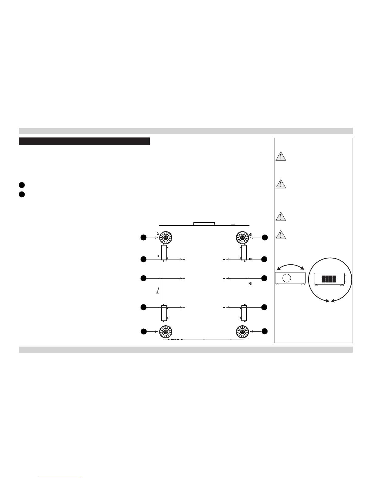
2. Mount the projector, ensuring that it is at a suitable distance from the screen for the image to ll the screen. Set the adjustable feet so that
the projector is level, and perpendicular to the screen.
The drawing below shows the positions of the feet for table mounting, and the xing holes for ceiling mounting.
1
Four adjustable feet
2
Six M6 holes for ceiling mount
The screws should not penetrate more than 15 mm into the body of the projector.
Notes
Always allow the projector
to cool for 5 minutes before
disconnecting the power or
moving the projector.
Ensure that there is at least 30
cm (12 in) of space between the
ventilation outlets and any wall,
and 10 cm (4 in) on all other
sides.
Do not stack more than 3
projectors.
Do not tilt the projector more than
±12° from side to side when in
use, as this may cause system
failure.
±12°
360°
1
2
1
1
1
2
2
2
2
2
Page 19

Digital Projection M-Vision 930 Series CHANGING THE LENS Installation and Quick-Start Guide
11
Rev A January 2014
Changing The Lens
Inserting a new lens
1. Remove the lens cover.
2. Insert the lens, keeping
the connector in upright
position.
3. Rotate the lens clockwise
until it clicks into place.
Notes
Before changing the lens,
always make sure the projector
is switched off and fully
disconnected from its power
supply.
When changing the lens, avoid
using excessive force as this may
damage the equipment.
Take care to preserve the original
lens packaging and protective caps
for future use.
Page 20

Digital Projection M-Vision 930 Series CHANGING THE LENS Installation and Quick-Start Guide
12
Rev A January 2014
Removing the lens
1. Push the button 1 all the way in.
2. Rotate the lens counterclockwise 2 until it disengages.
3. Slowly pull the lens out 3.
Notes
Before changing the lens,
always make sure the projector
is switched off and fully
disconnected from its power
supply.
When changing the lens, avoid
using excessive force as this may
damage the equipment.
Take care to preserve the original
lens packaging and protective caps
for future use.
1 32
Page 21

Digital Projection M-Vision 930 Series CHANGING THE FILTERS Installation and Quick-Start Guide
13
Rev A January 2014
Changing The Filters
The projector contains four identical replaceable lters accessible via the air inlets.
To replace the lters on the right-hand side of the projector:
1. Loosen the two screws on the cover of the air inlet and remove the cover. 2. Pull out the old lters.
3. Insert the new lters into the slots. 4. Reattach the cover and tighten the screws.
Notes
Beforechangingthelters,
always make sure the projector
is switched off and fully
disconnected from its power
supply.
Whenchangingthelters,avoid
using excessive force as this may
damage the equipment.
Page 22

Digital Projection M-Vision 930 Series CHANGING THE FILTERS Installation and Quick-Start Guide
14
Rev A January 2014
To replace the lters on the left-hand side of the projector:
1. Loosen the three screws on the cover of the air inlet and remove the cover. 2. Pull out the old lters.
3. Insert the new lters into the slots. 4. Reattach the cover and tighten the screws.
Notes
Page 23
Digital Projection M-Vision 930 Series CHANGING THE LAMPS Installation and Quick-Start Guide
15
Rev A January 2014
Changing The Lamps
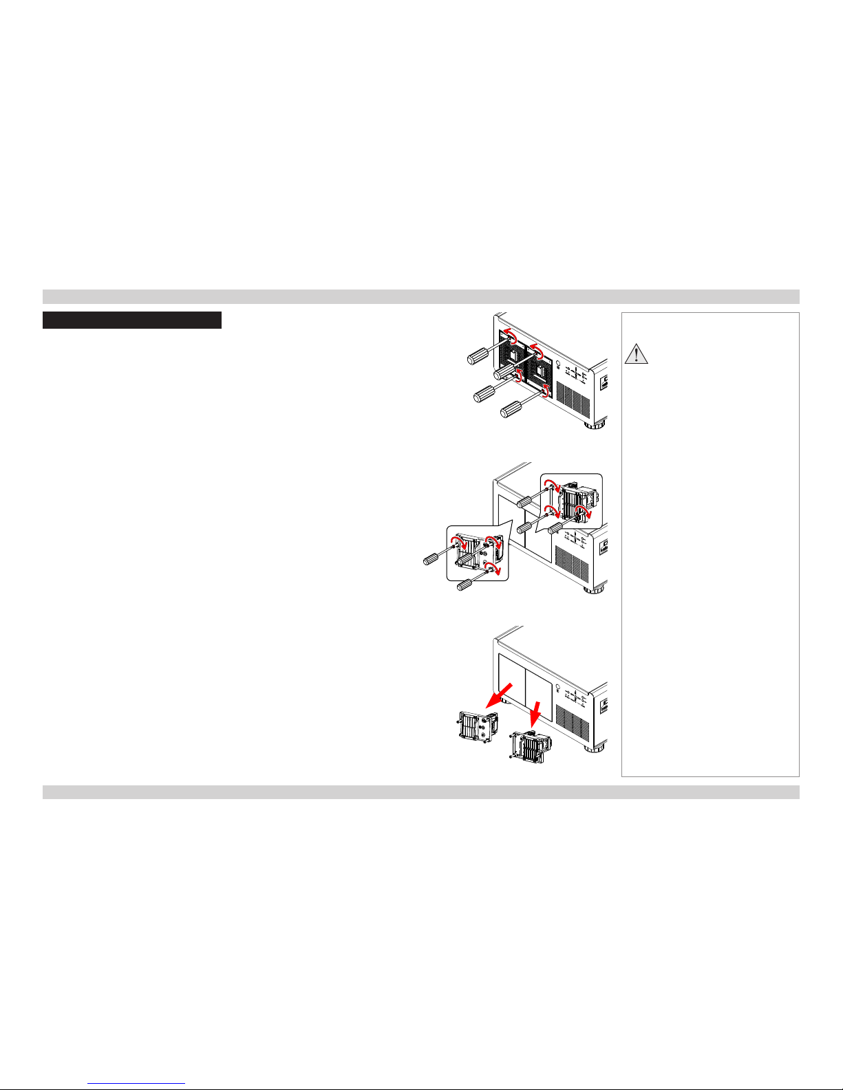
1. Remove the lamp cover (Fig. 1).
2. Loosen the screws of the lamp modules (Fig. 2).
3. Pull the lamp modules out of the enclosures (Fig. 3).
Fig. 1
Fig. 2
Fig. 3
Notes
Before removing the lamp
modules for replacement, turn
off the projector and unplug the
power cord.
Let the projector cool for
approximately 60 minutes.
Page 24

Digital Projection M-Vision 930 Series CHANGING THE LAMPS Installation and Quick-Start Guide
16
Rev A January 2014
4. Insert the new lamps (Fig 4).
5. Replace the lamp covers (Fig. 5).
6. Firmly secure the screws on the lamp covers (Fig. 6).
Notes
Fig. 4
Fig. 5
Fig. 6
Page 25

Digital Projection M-Vision 930 Series OPERATING THE PROJECTOR Installation and Quick-Start Guide
17
Rev A January 2014
Operating The Projector
Switching the projector on
1. Connect the power cable between the mains supply and the projector. Switch on at the switch next to the power connector.
Wait until the self-test has completed and the STANDBY indicator on the projector control panel shows amber. The system will be off and
the projector will be in STANDBY mode.
2. Press ON on the remote control or STBY on the control panel to switch the projector on. The ON indicator on the control panel ashes
blue for a few seconds while the lamp comes up to full brightness.
Switching the projector off
1. Press OFF on the remote control or STBY on the control panel, then press the button again to conrm.
The lamp will switch off, the ON indicator on the control panel will start ashing blue and the cooling fans will run for a short time until the
projector enters STANDBY mode.
2. If you need to switch the projector off completely, switch off at the mains power switch next to the power connector and then disconnect
the power cable from the projector.
Notes
See also Connecting The Power
Supply earlier in this guide.
The self-test is running when all the
LEDs on the control panel are lit.
Use only the power cable
provided.
Ensure that the power outlet
includes a ground connection as
this equipment MUST be earthed.
Handle the power cable carefully
and avoid sharp bends. Do not
use a damaged power cable.
Page 26
Digital Projection M-Vision 930 Series OPERATING THE PROJECTOR Installation and Quick-Start Guide
18
Rev A January 2014
Selecting an input signal or test pattern
Input signal
• Connect an image source to the projector. The signal should be automatically detected by the projector, and should be displayed within
two or three seconds.
• If more than one signal is connected, then select the input you want to display:
• Press one of the input buttons on the remote control, or
• Open the On-screen display (OSD) by pressing MENU. Highlight Input Select from the Main menu, then select an input signal
using the LEFT and RIGHT arrow buttons.
Test pattern
To display a test pattern:
• Open the OSD by pressing MENU. Highlight Test Patterns from the Alignment menu, then select a test pattern using the LEFT and
RIGHT arrow buttons.
Notes
For full details of how to use the
controls and the menu system, see
the Operating Guide.
Page 27
Digital Projection M-Vision 930 Series OPERATING THE PROJECTOR Installation and Quick-Start Guide
19
Rev A January 2014
Adjusting the lens
The lens can be adjusted using Lens Control from the Alignment menu, or using
the LENS button on the remote control. Both methods open the Lens Control
setting in the OSD.
Lens Control allows you to adjust Zoom, Focus and Shift using the arrow
buttons. The setting operates in Zoom/Focus Adjustment and Shift Adjustment
mode. While adjusting the lens, you can display either the source image or an
alignment grid.
When in Zoom/Focus Adjustment mode:
• Use the UP and DOWN arrow buttons to adjust Zoom.
• Use the LEFT and RIGHT arrow buttons to adjust Focus.
When in Shift Adjustment mode, use the arrow buttons to adjust Shift.
Press ENTER/SELECT to switch between modes as follows:
• Zoom/Focus Adjustment mode with the source image
• Shift Adjustment mode with the source image
• Zoom/Focus Adjustment mode with an alignment grid
• Shift Adjustment mode with an alignment grid
Lens Control
[Enter] Shift Adjustment
Zoom
Focus
Lens Control
[Enter] Zoom/Focus Adjustment
Shift
Notes
Page 28

Digital Projection M-Vision 930 Series OPERATING THE PROJECTOR Installation and Quick-Start Guide
20
Rev A January 2014
Adjusting the image
Orientation
• This can be set from the Alignment menu.
Highlight Projector Mode and choose from Front Tabletop, Front Ceiling, Rear Tabletop and Rear Ceiling.
Keystone
• This can be set from the Alignment > Warp menu.
Picture
• Settings such as Brightness and Contrast can be set from the Image menu.
• You can also set Brightness, Contrast or Gamma by pressing BRIGHTNESS, CONTRAST or GAMMA on the remote control.
Notes
Main Menu
Setup
Main Menu
Geometry
Main Menu
Image
For full details of how to use the
controls and the menu system, see
the Operating Guide.
Page 29
Rev A January 2014
CONNECTION GUIDE
M-Vision 930 Series
High Brightness Digital Video Projector
Page 30

Digital Projection M-Vision 930 Series IN THIS GUIDE Connection Guide
Rev A January 2014
IN THIS GUIDE
Signal Inputs ....................................................................................................... 23
Digital inputs and outputs ........................................................................................23
Analog inputs ............................................................................................................24
EDID on the DVI and VGA inputs .............................................................................25
Using HDMI/DVI switchers with the projector ........................................................25
3D connections .........................................................................................................26
3D sources up to 60Hz requiring frame doubling and left/right interleaving ...................26
Frame sequential 3D sources up to 120Hz .....................................................................26
Dual Pipe 3D ...................................................................................................................26
3D Sync ......................................................................................................................27
3D Sync in .......................................................................................................................27
3D Sync out ....................................................................................................................27
Control Connections ........................................................................................ 28
LAN connection examples .......................................................................................29
RS232 connection example ......................................................................................30
Page 31

Digital Projection M-Vision 930 Series SIGNAL INPUTS Connection Guide
23
Rev A January 2014
Signal Inputs
Digital inputs and outputs
1
HDBaseT
Receives digital signal from HDBaseT-compliant
devices.
2
HDMI 1, HDMI 2, Dual Pipe 3D
Two identical single HDMI 1.4 inputs which support
HDCP 1.1 and DVI 1.0.
Used together, the two sockets become a dual HDMI
input which supports Dual Pipe 3D.
Dual Pipe 3D supports sources up to 1920x1200
resolution at frame rates consistent with up to 148.5
Mpx/sec/pipe (including blanking).
3
DVI
This input has a DVI-I connector, which can receive
either analog (DVI-A) or digital (DVI-D) signal from a
compatible source.
Supports sources up to 1920x1200 resolution,
24-120 Hz. Supports HDCP.
Notes
For a complete listing of pin
congurations for all signal and
control connectors, see Appendix
E: Wiring Details in the Reference
Guide.
The DVI input is designed to handle
high bandwidth signals (above 60
Hz) in addition to lower frequencies.
Digital connections
1
HDBaseT
2
HDMI 1 & HDMI 2
3
DVI
3
2
1
Page 32

Digital Projection M-Vision 930 Series SIGNAL INPUTS Connection Guide
24
Rev A January 2014
Analog inputs
1
Component 1
2
Component 2
The Component inputs use colorspaces assigned from
the Colorspace setting in the Advanced menu. Set
Colorspace to Auto and the projector will automatically
detect and assign the colorspace as required.
Otherwise, assign the colorspace as follows:
• When using RGsB, set Colorspace to RGB PC or
RGB Video.
• When using YPbPr, set Colorspace to YPbPr.
• When using YCbCr, set Colorspace to YCbCr.
3
DVI
This input has a DVI-I connector, which can receive
either analog (DVI-A) or digital (DVI-D) signal from a
compatible source.
4
VGA
This input receives analog signals from a computer.
When using this input, it is best to use a fully wired VGA
cable to connect the source to the projector. This will
allow the source to determine the projector’s capabilities
via DDC and show an optimized image. Such cables
can be identied as they have a blue connector shell.
Analog connections
1
Component 1
2
Component 2
3
DVI
4
VGA
43
1 2
Notes
For a complete listing of pin
congurations for all signal and
control connectors, see Appendix
E: Wiring Details in the Reference
Guide.
Page 33

Digital Projection M-Vision 930 Series SIGNAL INPUTS Connection Guide
25
Rev A January 2014
EDID on the DVI and VGA inputs
If you are using a computer DVI card or another source that obeys the EDID protocol, the source will automatically congure itself to suit the
projector.
Otherwise refer to the documentation supplied with the source to manually set the resolution to the DMD™ resolution of the projector or the
nearest suitable setting. Switch off the source, connect to the projector, then switch the source back on again.
Using HDMI/DVI switchers with the projector
When using an HDMI/DVI source switcher with the projector, it is important to set the switcher so that it passes the projector EDID through to
the source devices. If this is not done, the projector may not be able to lock to the source or display the source correctly as its video output
timings may not be compatible with those of the projector. Sometimes this is called transparent, pass-through or clone mode. See your
switcher’s manual for information on how to set this mode.
1
Sources
2
Switcher
3
Projector
Notes
The EDIDs in the switcher should be the same as the one in the projector.
1 32
EDID
EDID
EDID
EDID
Page 34

Digital Projection M-Vision 930 Series SIGNAL INPUTS Connection Guide
26
Rev A January 2014
3D connections
3D sources up to 60Hz requiring frame doubling and left/right interleaving
1. Connect to either of the following inputs on the connection panel:
• HDMI 1
• HDMI 2
• HDBaseT
2. Set 3D Format in the Main > 3D Control menu to match the format of the incoming signal. Choose from Auto, Side-by-Side (Half) and
Top-and-Bottom.
Frame sequential 3D sources up to 120Hz
1. Connect to the DVI input.
2. Set DVI Frame Sequential in the Main > 3D Control menu to On.
Dual Pipe 3D
1. Connect the left eye output to the HDMI 1 socket and the right eye output to the HDMI 2 socket.
2. Set 3D Format in the Main > 3D Control menu to Dual Pipe.
Notes
For a complete listing of pin
congurations for all signal and
control connectors, see Appendix
E: Wiring Details in the Reference
Guide.
The Frame Packing format is
automatically detected by the
projector.
1
HDBaseT
2
DVI
3
HDMI 1 / Dual Pipe LEFT
4
HDMI 2 / Dual Pipe RIGHT
4
2
3
1
Page 35

Digital Projection M-Vision 930 Series SIGNAL INPUTS Connection Guide
27
Rev A January 2014
3D Sync
3D Sync in
• Sync input signal.
1. Connect the 3D sync from your graphics
card or server.
2. Set External 3D Sync in the Main >
3D Control menu to On.
3D Sync out
• Sync output signal. This may be affected by
the Sync Delay setting in the 3D Control
menu.
Connect this to your IR emitter or ZScreen.
Notes
For a complete listing of pin
congurations for all signal and
control connectors, see Appendix
E: Wiring Details in the Reference
Guide.
5643
3
3D input
4
3D Sync In
5
3D Sync Out
6
IR emitter or ZScreen
1
Sync In
2
Sync Out
2
1
Page 36

Digital Projection M-Vision 930 Series CONTROL CONNECTIONS Connection Guide
28
Rev A January 2014
Control Connections
1
LAN
• All of the projector’s features can be controlled via a LAN
connection, using commands described in the Remote
Communications Guide.
• Use a crossed LAN cable to connect directly to a computer, or an
uncrossed cable to connect to a network hub.
2
RS232
• All of the projector’s features can be controlled via a serial
connection, using commands described in the Remote
Communications Guide.
• Use a null-modem cable to connect directly to a computer, or a
straight cable to connect to a modem.
3
Trigger 1 & Trigger 2
The Trigger outputs are activated by one of the three following
conditions, as set in the Control menu:
• Screen trigger: can be connected to an electrically operated screen,
automatically deploying the screen when the projector starts up, and
retracting the screen when the projector shuts down.
• Aspect ratio trigger: can be used to control screen shuttering for
different aspect ratios.
• RS232 trigger: can be used to control the screen or screen
shuttering on receipt of an RS232 command
4
Wired remote control
• If infrared signals from the remote control cannot reach the projector
due to excessive distance or obstructions such as walls or cabinet
doors, you can connect an external IR repeater to the remote control
input, and position its IR sensor within range of the operator.
5
USB
The USB port is used for rmware updates only.
Notes
For a list of all commands used to
control the projector via LAN, see
the Remote Communications
Guide.
For a complete listing of pin
congurations for all signal and
control connectors, see Appendix
E: Wiring Details in the Reference
Guide.
Only one remote connection (RS232
or LAN) should be used at any one
time.
Plugging in the remote control cable
will disable the infrared receivers.
Control connections
1
5
2 3 4
Page 37

Digital Projection M-Vision 930 Series CONTROL CONNECTIONS Connection Guide
29
Rev A January 2014
LAN connection examples
The projector’s features can be controlled via a LAN connection, using a standard internet browser or a terminal-emulation program.
Notes
Computer
Projector
Projector
Un-crossed LAN cables
Hub or LAN
1
1
LAN
Projector
Computer
Crossed
LAN cable
Page 38

Digital Projection M-Vision 930 Series CONTROL CONNECTIONS Connection Guide
30
Rev A January 2014
RS232 connection example
Notes
1
1
RS232
Projector
Computer
Null-modem
cable
Page 39

Rev A January 2014
OPERATING GUIDE
M-Vision 930 Series
High Brightness Digital Video Projector
Page 40

Digital Projection M-Vision 930 Series IN THIS GUIDE Operating Guide
Rev A January 2014
IN THIS GUIDE
Using The Menus ............................................................................................... 33
Opening the OSD ......................................................................................................33
Opening a menu ........................................................................................................33
Exiting menus and closing the OSD .......................................................................33
Inside a menu ............................................................................................................34
Accessing sub-menus .....................................................................................................34
Executing commands ......................................................................................................34
Editing projector settings .........................................................................................35
Choosing a value from a list ............................................................................................35
Changing the value without viewing the list ....................................................................35
Using a slider to set a value ............................................................................................35
Using The Projector ......................................................................................... 36
Main menu .................................................................................................................36
Aspect Ratio ....................................................................................................................37
Presets ............................................................................................................................38
Overscan .........................................................................................................................39
3D Control .......................................................................................................................40
3D types ..........................................................................................................................41
Some 3D settings explained ...........................................................................................42
Main menu continued from previous page ......................................................................43
Frame rate multiplication in 3D images ...........................................................................43
Input Select .....................................................................................................................44
Resync ............................................................................................................................44
Image menu ...............................................................................................................45
Advanced Image menu .............................................................................................46
Colorspace ......................................................................................................................46
Gamma ...........................................................................................................................46
Color Temperature ..........................................................................................................46
Dynamic Black ................................................................................................................47
Adaptive Contrast ...........................................................................................................47
RGB Adjust .....................................................................................................................47
Fine Sync ........................................................................................................................48
Lamps menu ..............................................................................................................49
Alignment menu ........................................................................................................50
Lens Control ....................................................................................................................51
Center Lens ....................................................................................................................51
Warp ................................................................................................................................52
Blanking ..........................................................................................................................56
Edge Blend .....................................................................................................................57
Control menu .............................................................................................................59
OSD Settings ..................................................................................................................60
Service menu .............................................................................................................61
Factory Reset ..................................................................................................................61
Page 41

Digital Projection M-Vision 930 Series USING THE MENUS Operating Guide
33
Rev A January 2014
Using The Menus
Opening the OSD
Access the various menus using either the projector control panel or the remote
control. On either device,
• press the MENU button.
The on-screen display (OSD) opens showing the list of available menus.
Opening a menu
Move up and down the list using the UP and DOWN arrow buttons. To open a menu,
• press ENTER (on the remote control) or SELECT (on the control panel).
This guide refers to the above two buttons as ENTER/SELECT.
Exiting menus and closing the OSD
To go back to the previous page,
• press MENU.
When you reach the top level, pressing MENU will close the OSD.
Notes
Projector control panel
2
PIC
MUTE
4
ENTER
SOURCE
3
6
1
ASPECT
RATIO
MENU
USER MEMORY
|
ON POWER OFF
Remote control
On-screen display (OSD): top level
(list of available menus)
ENTER
ON ERROR
LED STATUS STANDBY
MENU STBY
INPUT
Select Item
[Enter] Submenu
[Menu] Exit
IMAGE
ADVANCED IMAGE
LAMPS
ALIGNMENT
CONTROL
MAIN
SERVICE
Page 42

Digital Projection M-Vision 930 Series USING THE MENUS Operating Guide
34
Rev A January 2014
Inside a menu
When you open a menu, the page consists of the following elements:
• Title bar at the top
Shows which menu (and sub-menu) you have accessed.
• Highlighted item
• Available and unavailable items
Unavailable items appear grayed out. Whether an item is available may
depend on other settings.
• Text next to each item
Shows whether the item:
• has a value that can be changed (shows the current value)
• opens a sub-menu (< Enter >)
• executes a command (< Execute >)
Accessing sub-menus
Use the UP and DOWN arrow buttons to highlight the sub-menu, then press
ENTER/SELECT.
Executing commands
If the item contains a command, press ENTER/SELECT to execute it.
You may be asked for conrmation. Use the LEFT and RIGHT arrow buttons
to select your answer and then press ENTER/SELECT.
Notes
The highlighted item has white text
on a blue background.
Inside a menu
Reset Everything
Yes No
Conrmation dialog
MENU>>Sub-menu>>
Select Item
Adjust
[Menu] Return
Menu Item
Unavailable Item
Slider
Sub-menu
Command
Highlighted Item
Value
Value
Numeric value
< Enter >
< Execute >
Value
Page 43
Digital Projection M-Vision 930 Series USING THE MENUS Operating Guide
35
Rev A January 2014
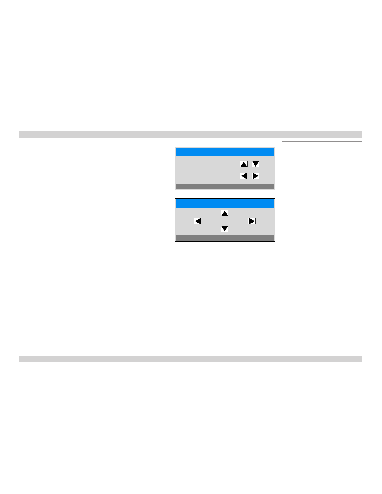
Editing projector settings
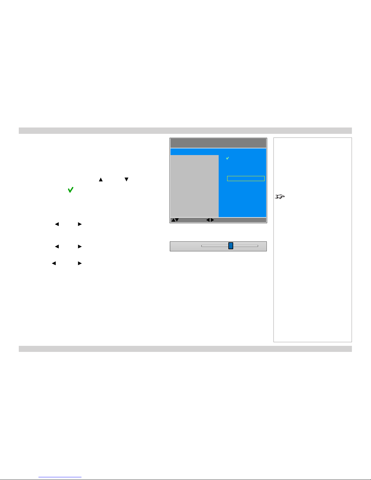
If the highlighted menu item is a setting with a list of values to choose from, you
can change the value in two different ways.
Choosing a value from a list
To access the list of values and then make a selection:
1. Highlight the menu item and press ENTER/SELECT.
2. On the new page that opens, use the UP and DOWN arrow buttons to
highlight a value, then press ENTER/SELECT again.
A green “check” symbol marks the current selection.
3. Press MENU to exit the list.
Changing the value without viewing the list
Some menu items allow you to switch to the next or previous value without
viewing the list:
• Press the LEFT or RIGHT arrow button.
Using a slider to set a value
Some parameters with a numeric value open a slider. To set such a parameter:
1. Press the LEFT or RIGHT arrow button, or ENTER/SELECT. The arrow
buttons will open the slider and adjust the value at the same time.
ENTER/SELECT will open the slider without altering the initial value.
2. Use the LEFT and RIGHT arrow buttons to move the slider.
3. When ready, press MENU to exit the slider.
Notes
Some menu items may be
unavailable due to settings in other
menus. Unavailable menu items
appear gray.
List of values
Parameter 101
Slider
MENU>>
Select Item
Adjust
[Menu] Return
Item
Unavailable Item
Item
Item
Item
Highlighted Item
Current Value
Value
Value
Highlighted Value
Value
Value
Page 44

Digital Projection M-Vision 930 Series USING THE PROJECTOR Operating Guide
36
Rev A January 2014
Using The Projector
The projector settings are grouped into seven menus as shown in the illustration.
Main menu
Selecting Main from the top level opens the Main menu.
Notes
If no input is connected, the Image
and Advanced Image menus will
be unavailable.
Select Item
[Enter] Submenu
[Menu] Exit
IMAGE
ADVANCED IMAGE
LAMPS
ALIGNMENT
CONTROL
MAIN
SERVICE
MAIN >>
Select Item
Adjust
[Menu] Return
Presets
Overscan
3D Control
Input Select
Resync
Aspect Ratio
< Enter >
Off
< Enter >
HDMI 1
< Execute >
16:10
Page 45

Digital Projection M-Vision 930 Series USING THE PROJECTOR Operating Guide
37
Rev A January 2014
Main menu continued from previous page
Aspect Ratio
Choose from:
• 16:9
• TheaterScope
• 4:3
• 4:3 Narrow
• 16:10
• 5:4
• Native
To change the aspect ratio:
1. From the Main menu, open Aspect Ratio.
2. From the list on the right, select a new aspect ratio and press
ENTER/SELECT.
Notes
For examples of how the different
aspect ratios affect screen
dimensions, see Aspect Ratios
Explained in the Reference Guide.
MAIN >>
Select Item
Adjust
[Menu] Return
Presets
Overscan
3D Control
Input Select
Resync
Aspect Ratio
TheaterScope
4:3
4:3 Narrow
16:10
5:4
16:9
Native
Page 46

Digital Projection M-Vision 930 Series USING THE PROJECTOR Operating Guide
38
Rev A January 2014
Main menu continued from previous page
Presets
The current image settings can be saved as a preset, which you can recall later.
The default settings can be recalled at any time as well.
Up to four custom presets can be stored for each input source you use.
The following settings are saved in a preset:
• From the Main menu — Aspect Ratio and Overscan
• From the Image menu — Brightness, Contrast, Saturation, Hue,
Sharpness and Noise Reduction
• From the Advanced Image menu — Colorspace, Gamma,
Color Temperature, Color Gamut, RGB Adjust, RGB Gains and Adaptive
Contrast
To recall a saved preset:
• Highlight Recall Preset and then use the LEFT and RIGHT arrow
buttons to select preset A, B, C, D, or Default.
To save a preset:
• Highlight Save Preset and then use the LEFT and RIGHT arrow
buttons to select preset A, B, C, or D.
Press MENU to leave the Presets page.
Alternatively, you can recall presets A, B and C with the USER MEMORY buttons
on your remote control.
MAIN >> Presets >>
Select Item
Adjust
[Menu] Return
Save Preset
Recall Preset
Preset B
Preset C
Preset D
Default
Preset A
2
PIC
MUTE
4
B
SHARP
ENTER
SOURCE
3
6
1
ASPECT
RATIO
MENU
USER MEMORY
CA
|
ON POWER OFF
1
USER MEMORY buttons on the remote control
1
Notes
Page 47

Digital Projection M-Vision 930 Series USING THE PROJECTOR Operating Guide
39
Rev A January 2014
Main menu continued from previous page
Overscan
Use this setting to compensate for noisy or badly dened image edges.
Crop removes unwanted artifacts from the edges of your image by cropping the
edges. Zoom increases the size of the image to force the edges off-screen.
To enable Overscan:
1. On the Main menu, highlight Overscan.
2. Use the LEFT and RIGHT arrow buttons to select Crop or Zoom.
Notes
MAIN >>
Select Item
Adjust
[Menu] Return
Presets
Overscan
3D Control
Input Select
Resync
Aspect Ratio
< Enter >
Off
< Enter >
HDMI 1
< Execute >
16:10
Image with noisy edges Overscanned image
Page 48

Digital Projection M-Vision 930 Series USING THE PROJECTOR Operating Guide
40
Rev A January 2014
Main menu continued from previous page
3D Control
Use this sub-menu to enable, disable and set up 3D input, as follows:
• 3D Format — Off, Auto, Side by Side (Half), Top and Bottom and
Dual Pipe.
• DLP Link — On (if you are using 3D glasses that can utilise the DLP Link®
signal embedded in the image) and Off
• 3D Swap — Normal and Rever se (set to Rever se if the left- and right-eye
images are displayed in the wrong order)
• Dark Time — 1ms, 1.5ms, 2ms and 2.5ms. Set to reduce the effect of
images overlapping while the glasses are switching
• Sync Delay — use the LEFT and RIGHT arrow buttons to compensate
for signal processing delays in the projector.
• 1080p24 3D Display — Sets the frame rate multiplication for Frame Packed
3D. If you set this to 144Hz, 30 lines are cropped from the top and bottom of
the frame; 96 Hz displays the full frame.
• DVI Frame Sequential
• External 3D Sync
MAIN >> 3D Control >>
Select Item
Adjust
[Menu] Return
3D Swap
Dark Time
Sync Delay
1080p24 3D Display
DVI Frame Sequential
3D Format
Normal
1ms
100
96Hz
Off
Auto
External 3D Sync Off
DLP Link Off
Notes
For further information about
supported 3D formats, see 3D
connections in the Connection
Guide.
If 3D Format is set to Off, or if
no 3D signal is detected in Auto
mode, the following settings will be
unavailable:
• DLP Link
• 3D Swap
• Dark Time
• Sync Delay
Frame Sequential is supported on
the DVI input only.
3D video is only possible on the
HDMI, HDBaseT and DVI inputs.
The Frame Packing format is
automatically detected by the
projector.
See also 3D types and Some 3D
settings explained further in this
guide.
Page 49

Digital Projection M-Vision 930 Series USING THE PROJECTOR Operating Guide
41
Rev A January 2014
Main menu continued from previous page
3D types
In most situations you can use the Auto setting to have the projector automatically detect the
format. Otherwise, consider the notes below to help you set up the 3D input manually.
The following 3D formats are supported:
• Dual Pipe (LEFT and RIGHT)
The left and right eye images are delivered on two separate HDMI links, which the projector
will interleave for 3D display.
• Frame Packing
This format will be detected, re-synchronised, frame-multiplied and displayed at 144 Hz with
the left eye / right eye dominance automatically extracted from the video data. You need to
optimize Dark Time and Sync Delay manually to suit your chosen switching glasses.
• Top-and-Bottom
Sets the projector to reformat the video frames and map them to the display with the left eye /
right eye dominance automatically extracted from the video data. You need to optimize Dark
Time and Sync Delay manually to suit your chosen switching glasses.
• Side-by-Side (Half): interlaced and progressive, 50 and 60Hz
The side-by-side image will be de-interlaced (if appropriate), resized and then sequentially
displayed at 100 or 120 Hz. The left eye / right eye dominance will be automatically extracted
from the video data, however you will need to optimize Dark Time and Sync Delay manually
to suit your chosen switching glasses.
Dark Time and Sync Delay need to be set only once, to optimize the image for the glasses in
use.
L
R
Frame Packing
L
R
Top-and-Bottom
L R
Side-by-Side (Half)
L
R
Dual Pipe
HDMI 1
HDMI 2
Notes
Page 50

Digital Projection M-Vision 930 Series USING THE PROJECTOR Operating Guide
42
Rev A January 2014
Main menu continued from previous page
Some 3D settings explained
Dark Time
Ghosting can be caused by the left and right images
overlapping during the time that the ZScreen or 3D
glasses are switching. Dark Time allows you to
minimize this effect.
3D Swap
The outgoing 3D frames are in pairs - the dominant
frame being presented rst. You can determine which
frame should be the dominant one.
By convention the default setting is Left.
Sync Delay
The sync signal from the 3D server will be in phase with
the frames generated by its graphics card. However,
to compensate for processing delays in the projector,
Sync Delay introduces a delay to the sync output
signal sent to the ZScreen or 3D glasses.
Fully on
Fully off
Left
Right
Dark
time
Dark
time
Dark
time
Dominance Left
Dominance Right
LEFT 1 RIGHT 1 LEFT 2 RIGHT 2 LEFT 3 RIGHT 3
LEFT 3RIGHT 1 LEFT 1 RIGHT 2 LEFT 2 RIGHT 3
Incoming
video
Incoming
sync signal
Video signal with
processing delays (and
dark time adjustment)
Sync output signal
after delay adjustment
Notes
In order to achieve maximum light
output and a smooth grayscale,
whilst eliminating ghosting,
the following procedure is
recommended:
1. Set Dark Time to a value
appropriate to the glasses or
ZScreen, say 1 ms or 1.5 ms.
2. Adjust Sync Delay time to eliminate
ghosting and achieve a smooth
grayscale.
3. Repeat steps 1 and 2 until the best
result is obtained.
Page 51

Digital Projection M-Vision 930 Series USING THE PROJECTOR Operating Guide
43
Rev A January 2014
Main menu continued from previous page
Frame rate multiplication in 3D images
When displaying a low frame rate 3D video, the projector
multiplies the frame rate to obtain a icker-free image. For
example, a 60Hz frame rate is doubled to 120 Hz, or a 48 Hz
frame rate is tripled to 144 Hz.
Frame rate multiplication is an automatic process. It occurs in
the background and cannot be modied by the user.
Notes
L1
R1
L2 R2
L1L1R1 R2L2 L3R2
R1 L3
L2
IN
OUT
x2 example
Page 52

Digital Projection M-Vision 930 Series USING THE PROJECTOR Operating Guide
44
Rev A January 2014
Main menu continued from previous page
Input Select
This setting controls the input source used by the projector. Choose from the
following input sources:
• HDMI 1
• HDMI 2
• RGB
• COMP 1
• COMP 2
• DVI
• HDBaseT
To change the input source, highlight Input Select, and then:
• Press ENTER/SELECT and then select a source from the list.
Resync
Press ENTER/SELECT to force the projector to resynchronize with the current
input signal.
Notes
See Signal Inputs in the
Connection Guide for further
information about the available
inputs and connections.
MAIN >>
Select Item
Adjust
[Menu] Return
Presets
Overscan
3D Control
Input Select
Resync
Aspect Ratio
< Enter >
Off
< Enter >
HDMI 1
< Execute >
16:10
Page 53

Digital Projection M-Vision 930 Series USING THE PROJECTOR Operating Guide
45
Rev A January 2014
Image menu
Highlight the setting you wish to edit, and then press ENTER/SELECT, or the
LEFT or RIGHT arrow button to open the slider.
Use the LEFT and RIGHT arrow buttons to adjust the slider.
Press MENU to close the slider.
Notes
IMAGE >>
Select Item
Adjust
[Menu] Return
Contrast
Brightness
Saturation
Hue
Sharpness
Picture Mode
100
100
100
100
0
Bright
Noise Reduction 0
Page 54

Digital Projection M-Vision 930 Series USING THE PROJECTOR Operating Guide
46
Rev A January 2014
Advanced Image menu
Colorspace
In most cases, the Auto setting determines the correct colorspace to use. If it
does not, you can choose a specic colorspace:
Choose from Auto, YPbPr, YCbCr, RGB PC and RGB Video.
Gamma
Choose a de-gamma curve from 1.0, 1.8, 2.0, 2.2, 2.35 and 2.5.
Used correctly, the Gamma setting can improve contrast while maintaining good
details for blacks and whites.
If excess ambient light washes out the image and it is difcult to see details in dark
areas, lower the Gamma setting to compensate. This improves contrast while
maintaining good details for blacks. Conversely, if the image is washed out and
unnatural, with excessive detail in black areas, increase the setting.
Color Temperature
Choose a value from 5400 (warmer) to 9300 (cooler) or Native (no correction).
Highlight the setting you wish to edit, and then either press ENTER/SELECT to
access it, or use the LEFT and RIGHT arrow buttons to switch between
values.
Press MENU to go back.
Notes
ADVANCED IMAGE >>
Select Item
Adjust
[Menu] Return
Gamma
Color Temperature
Adaptive Contrast
RGB Adjust
Fine Sync
Colorspace
2.2
6500K
Off
< Enter >
< Enter >
Auto
Off
Dynamic Black
Page 55

Digital Projection M-Vision 930 Series USING THE PROJECTOR Operating Guide
47
Rev A January 2014
Advanced Image menu continued from previous page
Dynamic Black
Allows for increased contrast in darker scenes by modulating the light source.
Adaptive Contrast
Expands the light and dark portions of the contrast curve of the image, depending
on the mean luminance of the image.
RGB Adjust
Adjust the RGB offset and gain settings to improve the color balance of the
projected image.
Highlight the setting you wish to edit, and then press ENTER/SELECT, or the
LEFT or RIGHT arrow button to open the slider.
Use the LEFT and RIGHT arrow buttons to adjust the slider.
Press MENU to close the slider.
Notes
ADVANCED IMAGE >> RGB Adjust >>
Select Item
Adjust
[Menu] Return
Green Offset
Blue Offset
Red Gain
Green Gain
Blue Gain
Red Offset
100
100
100
100
100
100
Page 56

Digital Projection M-Vision 930 Series USING THE PROJECTOR Operating Guide
48
Rev A January 2014
Advanced Image menu continued from previous page
Fine Sync
• V Position and H Position
Set the sliders as required.
• Phase
Adjusts the phase of the pixel sampling clock relative to the incoming signal.
Adjust the phase if noise is visible.
• Tracking
Adjusts the frequency of the pixel sampling clock. Flicker or vertical banding
indicate poor tracking.
• Sync Level
Adjusts the voltage level of the signal detection circuitry. Adjust if the projector
loses sync during scenes where the signal drops below black.
Highlight the setting you wish to edit, and then press ENTER/SELECT, or the
LEFT or RIGHT arrow button to open the slider.
Use the LEFT and RIGHT arrow buttons to adjust the slider.
Press MENU to close the slider.
Notes
Some of the settings within the Fine
Sync sub-menu, Phase, Tracking
and Sync Level, affect only RGB
and Component input sources.
These settings are not available
if the projector is using a different
source.
Adjust the Phase after adjusting
Tracking.
ADVANCED IMAGE >> Fine Sync >>
Select Item
Adjust
[Menu] Return
H Position
Phase
Tracking
Sync Level
V Position
100
100
100
100
100
Page 57
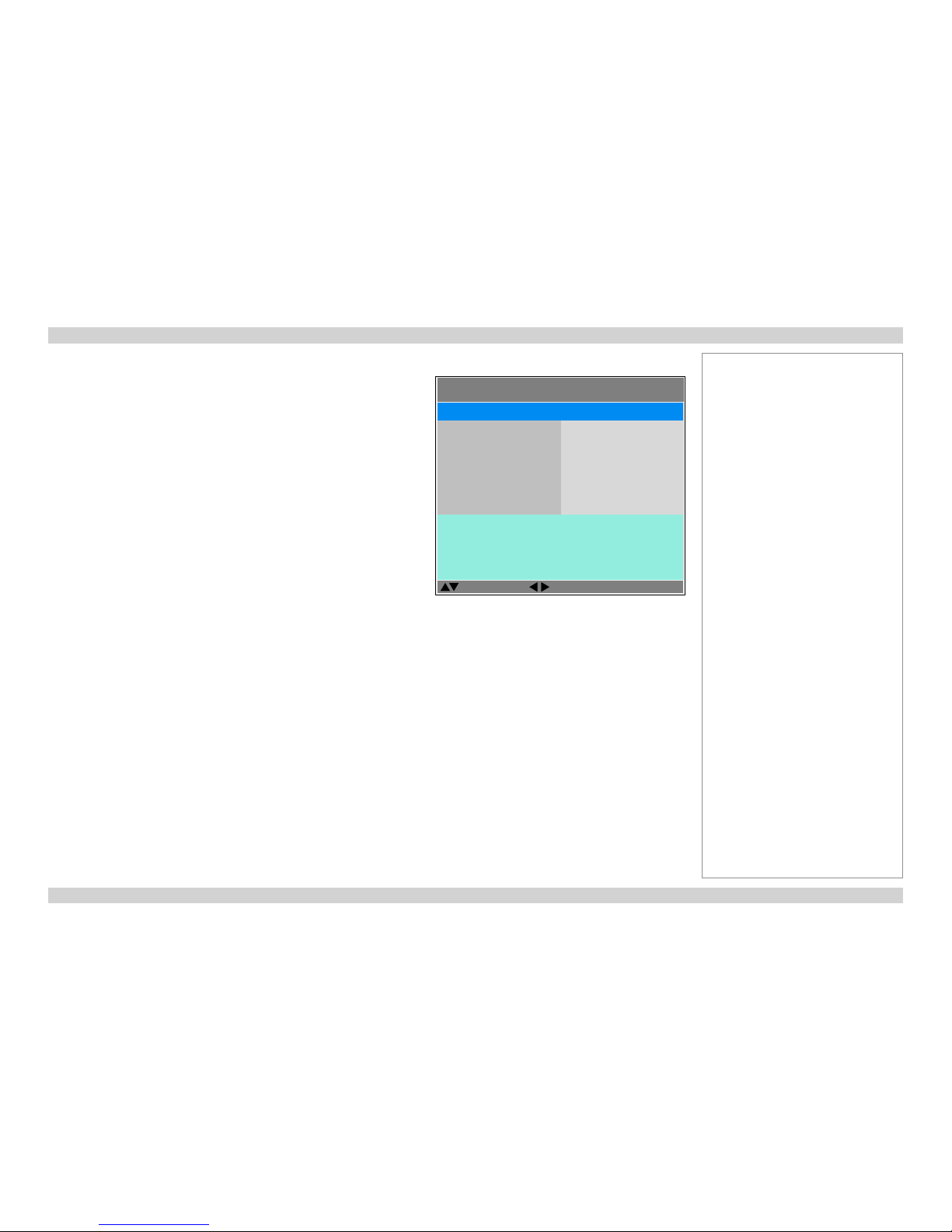
Digital Projection M-Vision 930 Series USING THE PROJECTOR Operating Guide
49
Rev A January 2014
Lamps menu
• Lamp Mode
Eco will automatically set the lamp power to 80%. Normal will set the power
to 92%.Set to Power if you wish to adjust the power manually, from 80% to
100%.
• Power
Use the slider to set lamp power. This setting is only available if Lamp Mode
is set to Power.
• Lamp Select
Choose between Single, Dual, Lamp 1 and Lamp 2.
• High Altitude
On increases the fan speed to compensate for reduced air density at high
altitude.
The following menu items show information only:
• Lamp1 Status, Lamp2 Status
• Lamp1 Run Time, Lamp2 Run Time
Notes
LAMPS >>
Select Item
Adjust
[Menu] Return
Power
Lamp Select
High Altitude
Lamp Mode
20 (100%)
Dual
Off
Power
Lamp1 Status:
Lamp1 Run Time:
ON
76 HRS
Lamp2 Status: ON
Lamp2 Run Time: 76 HRS
Page 58
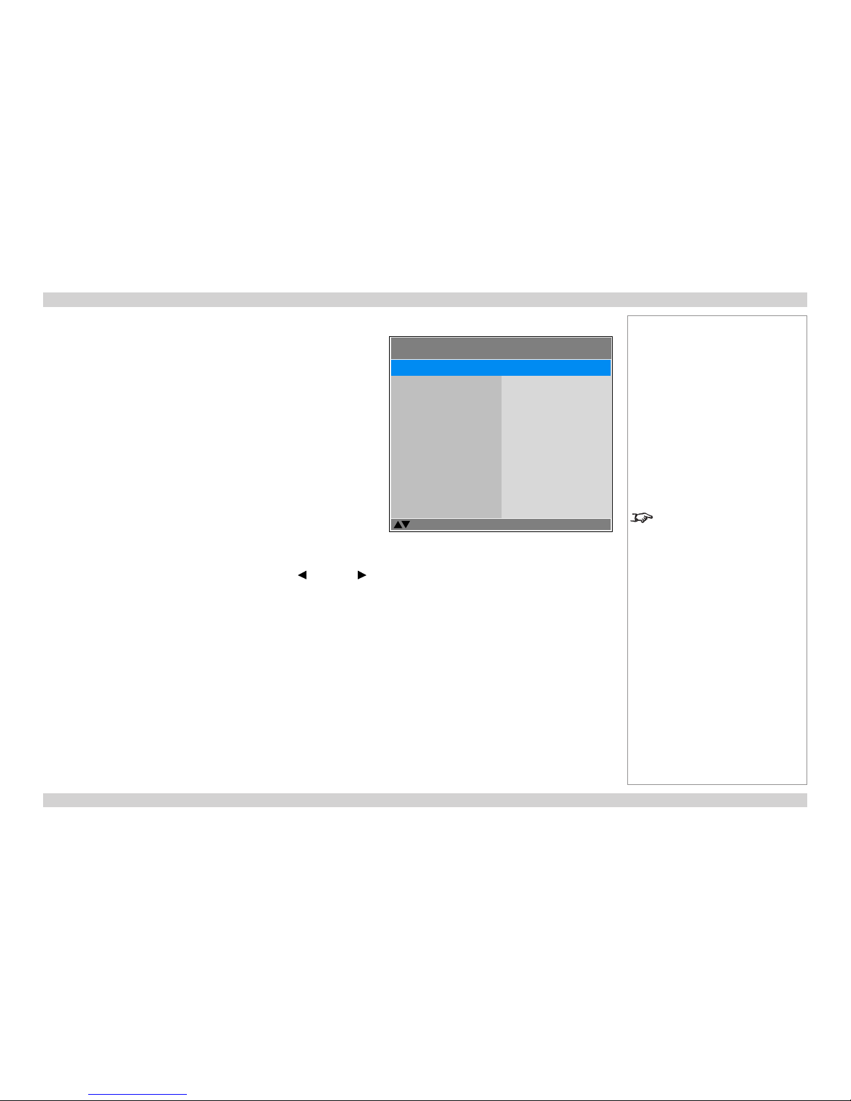
Digital Projection M-Vision 930 Series USING THE PROJECTOR Operating Guide
50
Rev A January 2014
Alignment menu
This menu contains the following settings:
• Lens Control
Adjust Focus, Zoom and Lens Shift.
• Center Lens
Center the lens.
• Warp
Compensate for image distortions caused by an unusual projection angle or
irregular screen surface.
• Blanking
Turn off areas around the edges of the image.
• Edge Blend
Create a combined image by blending the adjoining edges of two or more
individual images.
Test Patterns
Choose from:
...Off, White, Black, Red, Green, Blue, CheckerBoard, CrossHatch, V
Burst, H Burst, ColorBar...
Highlight the setting you wish to edit, and then either press ENTER/SELECT to
access it. When selecting a test pattern, you can use the LEFT and RIGHT
arrow buttons to switch between values.
Press MENU to go back.
Notes
Selecting a test pattern hides the
OSD. Pressing MENU then hides
the test pattern and shows the OSD.
ALIGNMENT >>
Select Item
[Enter] Submenu
[Menu] Exit
Center Lens
Warp
Blanking
Edge Blend
Test Patterns
Lens Control
< Enter >
< Enter >
< Enter >
< Enter >
Off
< Enter >
Page 59
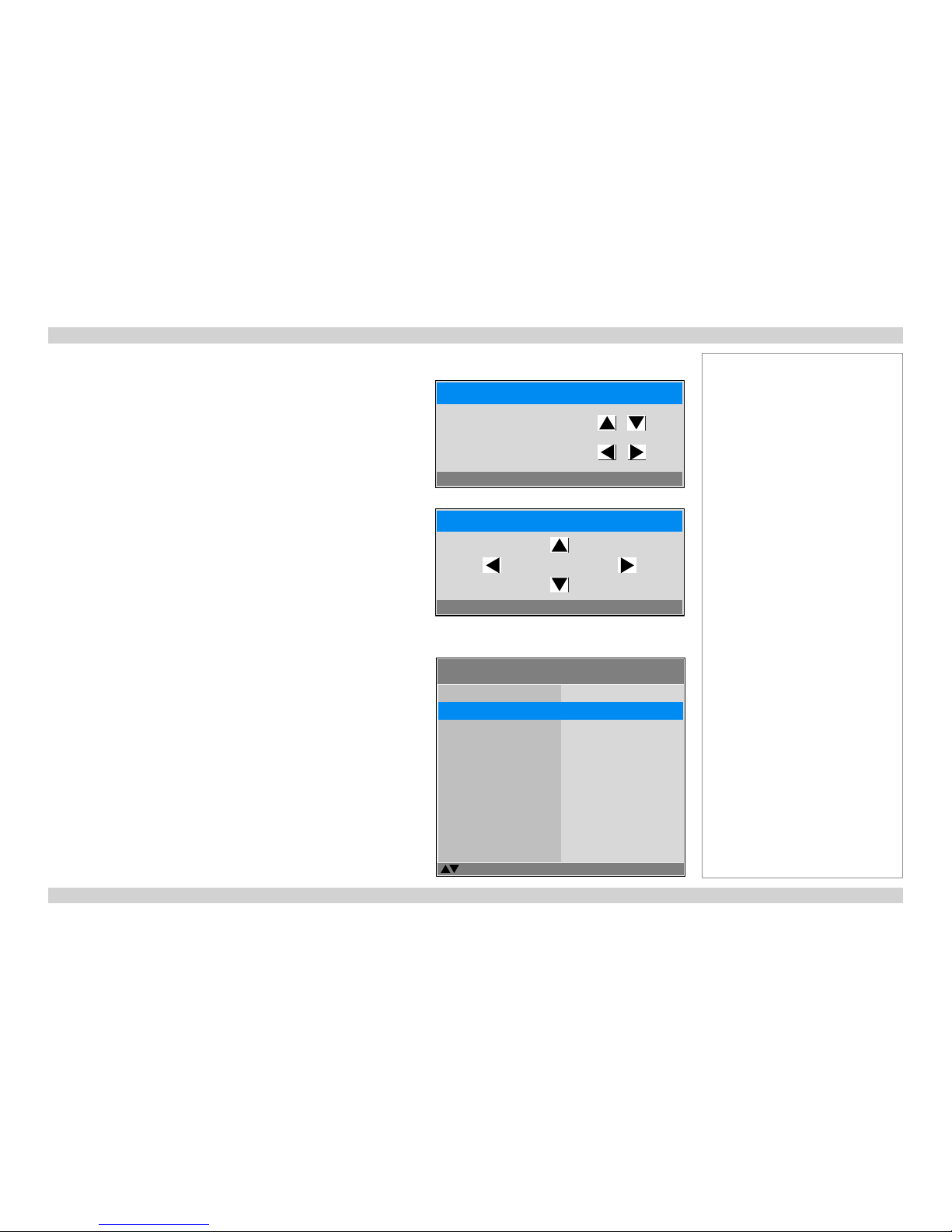
Digital Projection M-Vision 930 Series USING THE PROJECTOR Operating Guide
51
Rev A January 2014
Alignment menu continued from previous page
Lens Control
This settings operates in Zoom/Focus Adjustment and Shift Adjustment mode.
When in Zoom/Focus Adjustment mode:
• Use the UP and DOWN arrow buttons to adjust Zoom.
• Use the LEFT and RIGHT arrow buttons to adjust Focus.
When in Shift Adjustment mode, use the arrow buttons to adjust Shift.
Press ENTER/SELECT to switch between modes as follows:
• Zoom/Focus Adjustment mode with the source image
• Shift Adjustment mode with the source image
• Zoom/Focus Adjustment mode with an alignment grid
• Shift Adjustment mode with an alignment grid
...
Center Lens
Highlight Center Lens from the Alignment menu and press ENTER/SELECT.
Notes
ALIGNMENT >>
Select Item
[Enter] Submenu
[Menu] Exit
Center Lens
Warp
Blanking
Edge Blend
Test Patterns
Lens Control
< Enter >
< Enter >
< Enter >
< Enter >
Off
< Enter >
Lens Control
[Enter] Shift Adjustment
Zoom
Focus
Lens Control
[Enter] Zoom/Focus Adjustment
Shift
Page 60

Digital Projection M-Vision 930 Series USING THE PROJECTOR Operating Guide
52
Rev A January 2014
Alignment menu continued from previous page
Warp
• Keystone
Compensate for any distortion caused by the projector being in a different
horizontal or vertical plane to the screen.
• Rotation
Set the slider to rotate the image.
• Pincushion / Barrel
Set the slider to correct for any distortion caused by the screen being concave
or convex
• Corners
Set the sliders to stretch the image from each of the four corners.
• Reset
Reset all Warp settings to their factory default values.
Keystone example
1
The projector is positioned at an angle
2
The resulting image is distorted
3
The image is corrected when Keystone is applied
Notes
Some controls in the Warp menu
may be unavailable depending on
other settings.
ALIGNMENT >> Warp >>
Select Item
[Enter] Execute
[Menu] Exit
Rotation
Pincushion / Barrel
Top Left Corner
Top Right Corner
Bottom Left Corner
Keystone
< Enter >
< Enter >
< Enter >
< Enter >
< Enter >
< Enter >
Bottom Right Corner < Enter >
Reset < Enter >
1 2 3
Page 61

Digital Projection M-Vision 930 Series USING THE PROJECTOR Operating Guide
53
Rev A January 2014
Alignment menu continued from previous page
Keystone settings
1
Projector to the left
The projector is positioned
to the left of the screen.
To correct, apply a positive
Horizontal Keystone
value using the RIGHT
arrow button.
2
Projector to the right
The projector is positioned
to the right of the screen.
To correct, apply a negative
Horizontal Keystone
value using the LEFT arrow
button.
3
Projector high
The projector is positioned
above the screen at a
downward angle.
To correct, apply a negative
Vertical Keystone value
using the LEFT arrow
button.
4
Projector low
The projector is positioned
below the screen at an
upward angle.
To correct, apply a positive
Vertical Keystone value
using the RIGHT arrow
button.
5
Projector straight
The projector is directly
opposite the screen at a
right angle both horizontally
and vertically.
No correction is needed.
Notes
Horizontal and vertical keystone corrections
1
4
2
53
Page 62
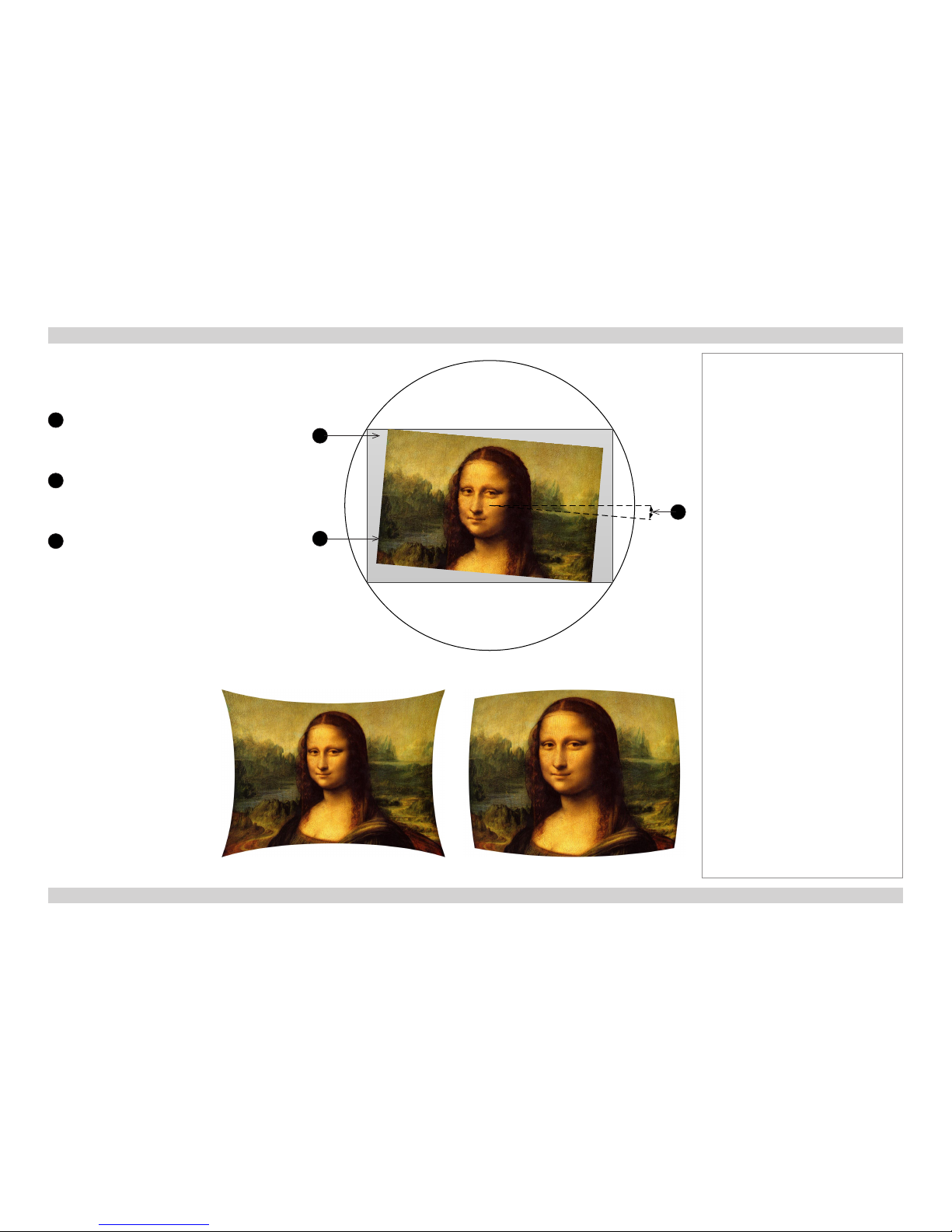
Digital Projection M-Vision 930 Series USING THE PROJECTOR Operating Guide
54
Rev A January 2014
Alignment menu continued from previous page
Rotation
1
DMD™ area
The DMD™ is not rotated. It still covers the
area that would be occupied by the image
without correction.
2
Rotated image
The image is smaller than the surrounding
DMD™ area. It is scaled in order to remain
within the DMD™ area.
3
Angle of rotation
The angle equals a quarter of the Rotation
setting.
In this example the angle is 5°, therefore
Rotation = 20.
Pincushion / Barrel
Notes
Pincushion Barrel
1
2
3
Page 63
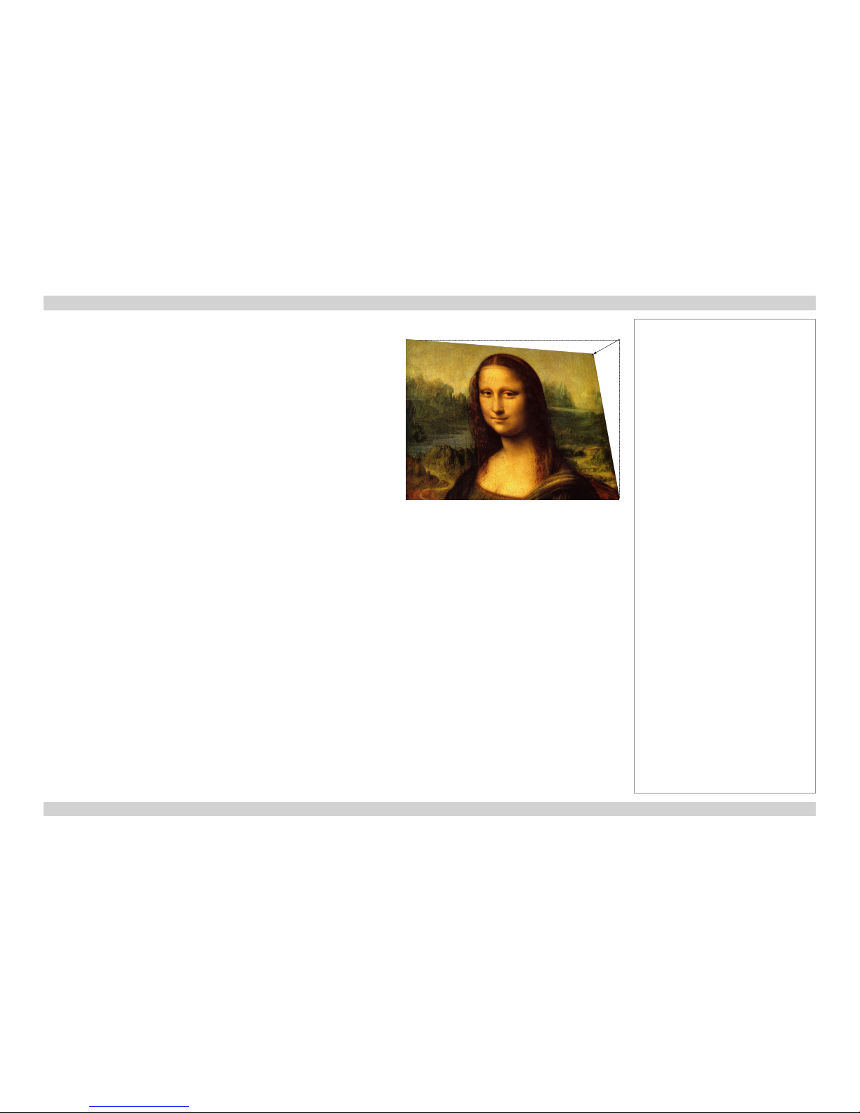
Digital Projection M-Vision 930 Series USING THE PROJECTOR Operating Guide
55
Rev A January 2014
Alignment menu continued from previous page
Corners
For each corner, apply horizontal and / or vertical correction as necessary to restore
the rectangular shape of the image.
In this illustration, the top right corner requires both horizontal and vertical correction.
Notes
Top Right Corner correction
Page 64

Digital Projection M-Vision 930 Series USING THE PROJECTOR Operating Guide
56
Rev A January 2014
Alignment menu continued from previous page
Blanking
Select the edge you wish to blank and adjust the slider to determine the amount.
ALIGNMENT >> Blanking >>
Select Item
[Menu] Exit
Bottom
Left
Right
Reset
Top
0
0
0
< Enter >
0
Adjust
Notes
Page 65
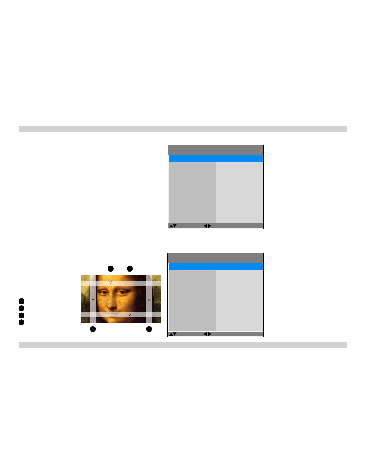
Digital Projection M-Vision 930 Series USING THE PROJECTOR Operating Guide
57
Rev A January 2014
Alignment menu continued from previous page
Edge Blend
• Status
Enable and disable Edge Blend
• White Level
Determine the width of the blended regions
• Black Level
Adjust black levels to compensate if the blended regions appear brighter than
the rest of the image.
• Reset
Reset all Edge Blend settings to their factory default values.
• Adjust Lines
When switched on, this feature makes the overlaps more visible and helps
adjust the physical position of the projectors in the array.
White Level
Use these sliders to set the width of the blended regions:
1
Top
2
Bottom
3
Left
4
Right
ALIGNMENT >> Edge Blend
Select Item
[Menu] Exit
White Level
Black Level
Reset
Adjust Lines
Status
< Enter >
< Enter >
< Enter >
On
On
Adjust
ALIGNMENT >> Edge Blend >> White Level
Select Item
[Menu] Exit
Left
Right
Top
0
0
0
0
Bottom
Adjust
3
1 2
4
Notes
Page 66

Digital Projection M-Vision 930 Series USING THE PROJECTOR Operating Guide
58
Rev A January 2014
Alignment menu continued from previous page
Black Level
Black in the blended regions appears less dark than in the rest of the image.
Use this menu to raise black levels in the unblended regions to achieve a uniform
black level.
Black level uplift is available for up to two edges, and they must be opposite each
other. For example, you can set black level to Top and Bottom, or to Left and
Right, but not to Top and Left.
1. Select Area
Stray light from the pond of mirrors of the DMD™ will elevate the black level
outside the blended regions. Adjust the slider to align the black level uplift
area with the edge of the pond of mirrors. The possible values are 8, 16, 24
and 32 pixels.
If required, adjust the opposite edge as well.
2. Adjust
Navigate to the Adjust group of settings and set All to the required amount of
black level correction. This will apply equal correction to the black levels of all colors.
If necessary, use the individual color sliders for ne adjustment.
ALIGNMENT >> Edge Blend >> Black Level
Select Item
[Menu] Exit
Top
Bottom
Left
Right
Select Area
0
Adjust
All 0
Red 0
Green 0
Blue 0
Adjust
Notes
Availability of black level area
controls depends on settings in the
White Level menu.
Enable Adjust Lines from the
Edge Blend menu to see the black
level uplift area.
Page 67

Digital Projection M-Vision 930 Series USING THE PROJECTOR Operating Guide
59
Rev A January 2014
Control menu
• OSD Settings
Adjust the appearance and position of the on-screen display.
• Blank Screen
Choose from Splash, Black, Blue and White.
• Projection Mode
Choose from Front Tabletop, Front Ceiling, Rear Tabletop and
Rear Ceiling.
• Auto Power Off
Set this to On if you want the projector to go into Standby mode when no
input source is detected for 20 minutes.
• Auto Power On
• Set this to On if you want the projector to start up immediately when the
mains is connected.
• Set this to Off if you want the projector to go into Standby mode when
the mains is connected. In this case, the projector will not start up until the
POWER button is pressed on the control panel or the remote control.
• Startup Splash
Set this to On if you want the DP logo to show when the projector is rst
switched on.
• Trigger1 and Trigger 2
Choose from Screen, 16:9, TheaterScope, 4:3, 4:3 Narrow or RS232 to
determine what will cause each trigger output to activate.
• Auto-Source
If this setting is On, the projector will automatically search for an input source
in case its current input is disconnected.
• Infrared Remote
Switch the remote control on and off.
• RS232 Control
• Set this to Projector RS232 if you want to use the RS232 port for RS232
connection.
• Set to HDBaseT RS232 if you want to use the HDBaseT port for RS232
connection.
Notes
If you turn the remote control off,
you can only turn it back on again
from the control panel.
CONTROL >>
Select Item
[Enter] Execute
[Menu] Return
Blank Screen
Projection Mode
Auto Power Off
Auto Power On
Startup Splash
OSD Settings
Splash
Front Tabletop
Off
Off
On
< Enter >
Trigger 1 Screen
Trigger 2
Auto Source
Infrared Remote
RS232 Control
Screen
Off
On
Projector RS232
Network < Enter >
Page 68

Digital Projection M-Vision 930 Series USING THE PROJECTOR Operating Guide
60
Rev A January 2014
Control menu continued from previous page
OSD Settings
• Menu Position
Select from the list where you want the OSD to appear on the screen.
• Menu Transparency
Choose between 0% (no transparency), 25%, 50% and 75%.
• Time Out
The menus will disappear if no buttons are pressed within the selected length
of time. If you want the menus to remain on screen permanently, then select
Always On.
• Message Box
If you do not want status messages to be displayed, set this to Off.
Notes
CONTROL >> OSD Settings
Select Item
[Menu] Return
Menu Transparency
Time Out
Message Box
Menu Position
0%
30 Seconds
On
Center
Adjust
Page 69

Digital Projection M-Vision 930 Series USING THE PROJECTOR Operating Guide
61
Rev A January 2014
Service menu
This menu gives information about software and hardware conguration, input
source and lamp operating times. It also allows you to restore the factory default
settings.
Factory Reset
To restore the factory default settings:
1. Navigate to Factory Reset and press ENTER/SELECT.
2. When prompted, use the LEFT and RIGHT arrow buttons to highlight the
Yes button and then press ENTER/SELECT to conrm your choice.
Notes
Reset Everything
Yes No
SERVICE >>
Select Item
[Enter] Execute
[Menu] Return
Factory Reset < Execute >
Model Name :
Serial Number :
M–Vision WUXGA 930–3D
W343AGFCY0002
Software Version 1 :
FPGA Version :
ME11–GE04–8B05–011D
LE03–RE01–3C3C
Active Source :
Signal Format :
HDMI1
67.39KHz/60.00Hz/148.50MHz
Lamp1 Run Time :
Lamp2 Run Time :
76 HRS
76 HRS
2.0–1.0_4.0–2.0
Software Version 2 :
1080p/60Hz
Page 70

Digital Projection M-Vision 930 Series Operating Guide
This page is intentionally left blank.
Page 71

Rev A January 2014
REMOTE COMMUNICATIONS GUIDE
M-Vision 930 Series
High Brightness Digital Video Projector
Page 72

Digital Projection M-Vision 930 Series IN THIS GUIDE Remote Communications Guide
Rev A January 2014
IN THIS GUIDE
Introduction ........................................................................................................ 65
Network setup ...........................................................................................................65
Serial Port setup ........................................................................................................65
Remote communications commands .....................................................................66
Examples ........................................................................................................................66
Command Guide ................................................................................................ 67
MAIN menu ................................................................................................................67
IMAGE menu ..............................................................................................................68
ADVANCED menu .....................................................................................................69
LAMPS menu .............................................................................................................70
ALIGNMENT menu ....................................................................................................70
CONTROL menu ........................................................................................................71
SERVICE menu ..........................................................................................................72
Miscellaneous commands ........................................................................................73
Page 73

Digital Projection M-Vision 930 Series INTRODUCTION Remote Communications Guide
65
Rev A January 2014
Introduction
The projector can be controlled by using an external control system or a PC via an RS232 or LAN interface, using a terminal-emulation
program.
Network setup
1. Connect the projector to a LAN network.
2. Open the Setup > Network menu and edit network settings. The default IP address is 192.168.0.100 and the TCP port number is 7000.
Serial Port setup
• Baud rate 9600 bps
• Data length 8 bits
• Stop bits one
• Parity none
• Flow control none
Notes
For details on connecting the
projector to an RS232 or LAN
network, see Control Connections
in the Connection Guide.
Page 74
Digital Projection M-Vision 930 Series INTRODUCTION Remote Communications Guide
66
Rev A January 2014
Remote communications commands
Commands are used to simulate menu operations and determine the settings of the projector, and use the following format:
• All commands consist of ASCII text strings starting with “op”, followed by the command name as shown in the Command Guide section
below. Depending on the command, these may be followed by operator and value. Each command line ends with an ASCII Carriage
Return character (code 13):
op command operator <value>
• The <command> string determines which setting the command will affect.
• Spaces are required before the command, operator and value.
• The <operator> string can take one of the following formats:
Operator type <operator> Description
Set
= <value>
Makes the setting take the <value>.
Get
?
Asks what the current value is.
The value is returned as an ASCII text string.
Increment
+
Increments the value.
Decrement
-
Decrements the value.
Execute Performs an action. No operator is entered for this type of command.
Examples
op aspect = 1
sets the aspect ratio to TheaterScope
op aspect ? asks what is the current aspect ratio
op resync commands the projector to resynchronize with the current input signal
op aspect=1 is an invalid instruction because of the missing spaces before the operator and the value
op zoomio +
zooms in the image
Notes
To set the default value of a
command, simply enter the
command name and
, without an
operator. For example
op aspect.ratio will set
the aspect ratio to 0 (Source).
The projector response begins with
“ACK:” , to show your input has
been acknowledged.
For example, if you send
op aspect.ratio = 1,
the projector will return
ACK:aspect.ratio = 1
and will change the aspect ratio
accordingly.
If your command has been rejected,
due to a syntax error or another
problem, the projector response will
be “ERR:” and a brief description of
the problem:
•ERR:Invalid Command - the
command is not recognized
•ERR:NA - the command is valid
but the projector is not in the
right mode to respond
•ERR:Command Execution
Fail - the command is valid but
the projector is not in the right
mode to respond
•ERR:Invalid Command
Header - the command header
is incorrect
•ERR:Invalid Command
Operating Type - the
operator does not match the
command
Page 75
Digital Projection M-Vision 930 Series COMMAND GUIDE Remote Communications Guide
67
Rev A January 2014
Command Guide
<command> <operator> <values>
MAIN menu
aspect = ?
0 = 16:9
1 = TheaterScope
2 = 4:3
3 = 4:3 Narrow
4=16:10
5=5:4
6=Native
recall.mem = ?
0 = Preset A
1 = Preset B
2 = Preset C
3 = Preset D
4 = Default
save.mem = ?
0 = Preset A
1 = Preset B
2 = Preset C
3 = Preset D
overscan = ?
0 = Off
1 = Crop
2 = Zoom
3d.format = ?
0 = Off
1 = Auto
2 = Side-by-Side (Half)
3 =Top-and-Bottom
4 = Dual Pipe
3d.sync = ?
0 = Normal
1 = Reverse
3d.dlplink = ?
0 = off
1 = on
3d.darktime = ?
0 = 1 ms
1 = 1.5 ms
2 = 2 ms
3 = 2.5 ms
Notes
3d.sync is identical to the 3D
Swap command in the MAIN menu.
Set to 0 (Normal) to use HDMI 1 for
the left eye and HDMI 2 for right; set
to 1 (Reverse) if you wish to reverse.
3d.darktime will only be carried
out if the projector is in 3D mode.
Page 76

Digital Projection M-Vision 930 Series COMMAND GUIDE Remote Communications Guide
68
Rev A January 2014
<command> <operator> <values>
MAIN menu (continued)
3d.syncdelay = ?
0 to 200 (integer)
3d.24p.mode = ?
0 = 96Hz
1 = 144Hz
input.sel = ?
0 = HDMI 1
1 = HDMI 2
2 = RGB
3 = COMP 1
4 = COMP 2
5 = DVI
6 = HDBaseT
resync
(execute)
IMAGE menu
picture.mode = ?
0 = Bright
1 = Presentation
2 = Video
bright = ?
0 to 200 (integer)
contrast = ?
0 to 200 (integer)
saturation = ?
0 to 200 (integer)
hue = ?
0 to 200 (integer)
sharp = ?
0 to 200 (integer)
nr = ?
0 to 200 (integer)
Notes
3d.syncdelay will only be
carried out if the projector is in 3D
mode.
Page 77
Digital Projection M-Vision 930 Series COMMAND GUIDE Remote Communications Guide
69
Rev A January 2014
<command> <operator> <values>
ADVANCED menu
color.space = ?
0 = Auto
1 = YPbPr
2 = YCbCr
3 = RGB-PC
4 = RGB-Video
gamma = ?
0 = 1.0
1 = 1.8
2 = 2.0
3 = 2.2
4 = 2.35
5 = 2.5
6 = S-Curve
color.temp = ?
0 = 5500K
1 = 6500K
2 = 7500K
3 = 9300K
4= Native
dblack = ?
0 = off
1 = on
adcontrast = ?
0 = off
1 = on
red.gain = ?
0 to 200 (integer)
green.gain = ?
0 to 200 (integer)
blue.gain = ?
0 to 200 (integer)
red.offset = ?
0 to 200 (integer)
green.offset = ?
0 to 200 (integer)
blue.offset = ?
0 to 200 (integer)
hori.pos = ?
0 to 200 (integer)
vert.pos = ?
0 to 200 (integer)
phase = ?
0 to 200 (integer)
tracking = ?
0 to 200 (integer)
sync.level = ?
0 to 200 (integer)
Notes
Page 78
Digital Projection M-Vision 930 Series COMMAND GUIDE Remote Communications Guide
70
Rev A January 2014
<command> <operator> <values>
LAMPS menu
lamps = ?
0 = Single
1 = Dual
2 = Lamp1
3 = Lamp2
lamp.mode = ?
0 = Economy
1 = Standard
2 = Power
lamp.power = ?
0 to 20 (77% to 100%)
altitude = ?
0 = auto
1 = high
lamp1.stat ?
0 = off
1 = on
lamp2.stat ?
0 = off
1 = on
lamp1.hours ?
(number)
lamp2.hours ?
(number)
total.hours ?
(number)
ALIGNMENT menu
horiz.offset + -
+ = right
- = left
vert.offset + -
+ = up
- = down
focus + -
zoomio + -
+ = zoom in
- = zoom out
lens.center
(execute)
Notes
Page 79
Digital Projection M-Vision 930 Series COMMAND GUIDE Remote Communications Guide
71
Rev A January 2014
<command> <operator> <values>
ALIGNMENT menu (continued)
pattern = ?
0 = Off
1 = White
2 = Black
3 = Red
4 = Green
5 = Blue
6 = Cyan
7 = Magenta
8 = Yellow
9 = ANSI Checkerboard
10 = Focus Grid
11 = V Burst
12 = H Burst
13 = Color bar
CONTROL menu
osd.menupos = ?
0 = Top Left
1 = Top Right
2 = Bottom Left
3 = Bottom Right
4 = Center
osd.trans = ?
0=0%
1=25%
2=50%
3=75%
osd.timer = ?
0 = OSD always on
1 = Display OSD for 10 sec.
2 = Display OSD for 30 sec.
3 = Display OSD for 60 sec.
osd.msgbox = ?
0 = off
1 = on
blank.screen = ?
0 = Logo
1 = Black
2 = Blue
3 = White
Notes
Page 80

Digital Projection M-Vision 930 Series COMMAND GUIDE Remote Communications Guide
72
Rev A January 2014
<command> <operator> <values>
CONTROL menu (continued)
proj.mode = ?
0 = Front Tabletop
1 = Front Ceiling
2 = Rear Tabletop
3 = Rear Ceiling
auto.poweroff = ?
0 = off
1 = on
auto.poweron = ?
0 = off
1 = on
startup.logo = ?
0 = disable
1 = enable
trig.1
trig.2
= ?
0 = Screen (Def)
1 = 16:9
2 = TheaterScope
3 = 4:3
4 = 4:3 Narrow
5 = RS-232
6 = RS-232:on
7 = RS-232:off
auto.source = ?
0 = disable
1 = enable
ir.enable = ?
0 = disable
1 = enable
SERVICE menu
model ?
ser.number ?
soft.version ?
act.source ?
signal ?
h.refresh ?
v.refresh ?
factory.reset
(execute)
Notes
A trigger can only be set to 6 (RS-
232:on) or 7 (RS-232:off) if it has
been set to 5 (RS-232) in advance.
Page 81

Digital Projection M-Vision 930 Series COMMAND GUIDE Remote Communications Guide
73
Rev A January 2014
<command> <operator> <values>
Miscellaneous commands
power.on
(execute)
power.off
(execute)
status ?
0 = standby
1 = warm up
2 = imaging
3 = cooling
4 = error
shutter ? =
0 = off
1 = on
net.ipaddr ?
Notes
Page 82

Digital Projection M-Vision 930 Series Remote Communications Guide
This page is intentionally left blank.
Page 83

Rev A January 2014
REFERENCE GUIDE
M-Vision 930 Series
High Brightness Digital Video Projector
Page 84

Digital Projection M-Vision 930 Series IN THIS GUIDE Reference Guide
Rev A January 2014
IN THIS GUIDE
The DMD™ ........................................................................................................... 78
Choosing A Lens ................................................................................................ 80
Basic calculation .......................................................................................................81
Basic calculation example .......................................................................................82
Full lens calculation ..................................................................................................83
Introducing TRC ..............................................................................................................83
Calculating TRC ..............................................................................................................84
Calculating the throw ratio with TRC ...............................................................................85
Full lens calculation example ..................................................................................86
Screen Requirements ...................................................................................... 87
Fitting the image to the DMD™ ................................................................................87
WUXGA images displayed full width ...............................................................................87
WUXGA images displayed with a height of 1080 pixels .................................................88
WUXGA images displayed full height .............................................................................89
Diagonal screen sizes ...............................................................................................90
Fitting the image to the screen ................................................................................91
Positioning the screen and projector ......................................................................92
Positioning The Image .................................................................................... 93
Maximum offset range ..............................................................................................95
Aspect Ratios Explained ................................................................................ 96
Aspect ratio examples ..............................................................................................97
Frame Rates And Pulldowns Explained ..................................................... 99
Interlaced and progressive scan .............................................................................99
Frame rates of image sources .................................................................................99
Pulldowns - conversion into destination formats ............................................... 100
2:3 (normal) pulldown .................................................................................................. 100
2:3:3:2 (advanced) pulldown ........................................................................................ 101
Appendix A: Lens Part Numbers ................................................................ 102
Appendix B: Lens Charts .............................................................................. 103
How to use the lens charts ........................................................................................... 103
TRC values applied in the charts ................................................................................. 104
Full DMD™ width images ............................................................................................ 105
1.25:1 images .............................................................................................................. 106
1.33:1 images .............................................................................................................. 107
Appendix C: Supported Signal Input Modes .......................................... 108
2D input modes ...................................................................................................... 108
3D input modes .......................................................................................................110
Appendix D: Menu Map .................................................................................. 112
MAIN .........................................................................................................................112
IMAGE ......................................................................................................................112
ADVANCED IMAGE .................................................................................................113
LAMPS ......................................................................................................................113
ALIGNMENT .............................................................................................................114
CONTROL ................................................................................................................116
SERVICE ..................................................................................................................116
Page 85

Digital Projection M-Vision 930 Series IN THIS GUIDE Reference Guide
Rev A January 2014
Appendix E: Wiring Details .......................................................................... 117
Signal inputs and outputs ......................................................................................117
VGA .............................................................................................................................. 117
HDMI 1 and 2 ............................................................................................................... 11 8
DVI ............................................................................................................................... 119
Component 2 ............................................................................................................... 120
Control connections .............................................................................................. 121
LAN .............................................................................................................................. 121
RS232 .......................................................................................................................... 121
Trigger 1 & Trigger 2 ....................................................................................................122
Wired remote control .................................................................................................... 122
USB .............................................................................................................................. 122
3D Sync IN and 3D Sync OUT ..................................................................................... 122
Appendix F: Glossary Of Terms ................................................................. 123
TechnicalSpecications .............................................................................. 134
Models ..................................................................................................................... 134
Inputs and outputs ................................................................................................. 135
Bandwidth ............................................................................................................... 135
Remote control and keypad .................................................................................. 135
Automation control ................................................................................................ 135
Color temperature .................................................................................................. 135
Lenses ..................................................................................................................... 136
Lens mount ............................................................................................................. 136
Mechanical mounting ............................................................................................ 136
Orientation .............................................................................................................. 136
Electricalandphysicalspecications ................................................................. 137
Safety & EMC regulations ..................................................................................... 137
IN THIS GUIDE (continued)
Page 86

Digital Projection M-Vision 930 Series THE DMD™ Reference Guide
78
Rev A January 2014
The DMD™
A DMD™ (Digital Micromirror Device™) is a true digital light modulator which utilises an array of up to 2.3 million moving aluminium mirrors,
with each one representing a pixel in the nal projected image. The outermost micromirrors in the array remain inactive (pond of mirrors)
and are not used in constructing the image.
1
Casing
2
Light shield
3
Pond of mirrors
4
Array
Each mirror element is suspended over address electrodes by a torsion hinge between two posts.
1
Support posts
2
Mirror element
3
Torsion hinges
4
Offset address electrode
Notes
DMD
2
3
4
1
Mirror element with tilt mechanism
2
1
3
4
Page 87
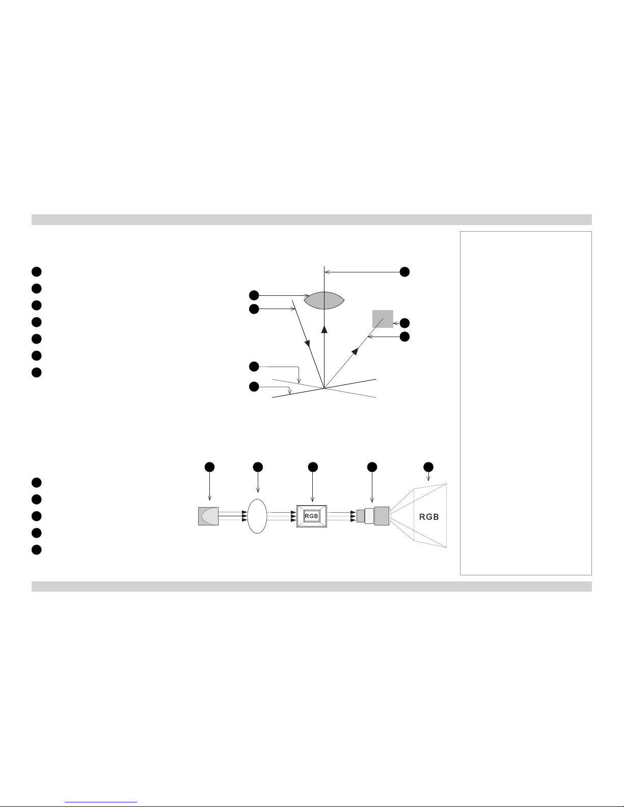
Digital Projection M-Vision 930 Series THE DMD™ Reference Guide
79
Rev A January 2014
Depending on the voltage polarity applied, each mirror will either tilt to the left to produce a bright pixel or to the right for a dark pixel. When
light is applied to the complete DMD™, only the light redirected from a mirror tilting to the left is projected.
1
Projection lens
2
Incoming light from the illumination module
3
Mirror element tilted to the right
4
Mirror element tilted to the left
5
Reectedlight,lefttilt
6
Light dump
7
Reectedlight,righttilt
The projector uses a color wheel to split white light from the lamp into its constituent red, green and blue. The color wheel sends red, green
and blue light sequentially to the DMD™. The modulated output of the DMD™ is synchronized with the color wheel to form the projected full
color image.
1
Lamp
2
Color wheel
3
DMD™ device
4
Projection lens
5
Full color image displayed on screen
Notes
Filtering process
white light RGB light RGB light
1 2 3 4 5
Light ow
1
2
3
4
5
6
7
Page 88

Digital Projection M-Vision 930 Series CHOOSING A LENS Reference Guide
80
Rev A January 2014
Choosing A Lens
A number of lenses are available. Which lens you choose depends on the screen size, image aspect ratio, throw distance and light output.
The following table shows all available lenses in order of their throw ratios:
Throw ratios Throw distance range
0.84 - 1.03 : 1 zoom lens 1.5 - 4 m (4.9 - 13.1 ft)
1.56 - 1.86 : 1 zoom lens 2 - 7 m (6.6 - 23 ft)
1.85 - 2.40 : 1 zoom lens 2.5 - 10 m (8.2 - 32.8 ft)
2.40 - 4.00 : 1 zoom lens 4 - 12 m (13.1 - 39.4 ft)
To choose a lens, either calculate the throw ratio required, or use the lens charts provided within this section.
Notes
For information about individual lens
part numbers, see Appendix A at
the end of this document.
Page 89

Digital Projection M-Vision 930 Series CHOOSING A LENS Reference Guide
81
Rev A January 2014
Basic calculation
Identify the required lens by calculating the throw ratio.
A throw ratio is the ratio of the throw distance to the screen width:
Throw distance
Screen width
Throw ratio =
1. Use the formula above to obtain the required throw ratio.
2. Match the throw ratio with a lens from the table below:
Throw ratios Throw distance range
0.84 - 1.03 : 1 zoom lens 1.5 - 4 m (4.9 - 13.1 ft)
1.56 - 1.86 : 1 zoom lens 2 - 7 m (6.6 - 23 ft)
1.85 - 2.40 : 1 zoom lens 2.5 - 10 m (8.2 - 32.8 ft)
2.40 - 4.00 : 1 zoom lens 4 - 12 m (13.1 - 39.4 ft)
3. Ensure the required throw distance is within the range covered
by the lens.
Notes
The basic calculation on this page
does not take into consideration
DMD™ and image size, which could
affect the throw ratio. For a more
complex and realistic calculation,
see Full lens calculation in this
section.
When calculating the throw ratio, be
sure to use identical measurement
units for both the throw distance and
the screen width.
For information about individual lens
part numbers, see Appendix A at
the end of this document.
1
2
1
Screen width
2
Throw distance
Page 90
Digital Projection M-Vision 930 Series CHOOSING A LENS Reference Guide
82
Rev A January 2014
Basic calculation example
1. Calculate the throw ratio using the formula.
Your screen is 3.5 m wide and you wish to place the projector
approximately 6.8 m from the screen. The throw ratio will then
be
6.8
3.5
= 1.94
2. Match the result with the lens table.
The lens matching a throw ratio of 1.94 is the 1.85 - 2.40 : 1
zoom lens.
3. Check whether the lens covers the required throw distance.
The range quoted for the 1.85 - 2.40 : 1 zoom lens is 2.5 - 10 m.
The required distance of 6.8 m is within the range.
Notes
The basic calculation on this page
does not take into consideration
DMD™ and image size, which could
affect the throw ratio. For a more
complex and realistic calculation,
see Full lens calculation in this
section.
For information about individual lens
part numbers, see Appendix A at
the end of this document.
INFORMATION YOU NEED FOR THIS CALCULATION
• The throw ratio formula:
Throw distance
Screen width
Throw ratio =
• The lens table:
Throw ratios Throw distance range
0.84 - 1.03 : 1 zoom lens 1.5 - 4 m (4.9 - 13.1 ft)
1.56 - 1.86 : 1 zoom lens 2 - 7 m (6.6 - 23 ft)
1.85 - 2.40 : 1 zoom lens 2.5 - 10 m (8.2 - 32.8 ft)
2.40 - 4.00 : 1 zoom lens 4 - 12 m (13.1 - 39.4 ft)
Page 91

Digital Projection M-Vision 930 Series CHOOSING A LENS Reference Guide
83
Rev A January 2014
Full lens calculation
Introducing TRC
The choice of lens will affect the image size and will address discrepancies between the
DMD™ resolution and the source.
When an image lls the height of the DMD™ but not the width, it uses less than 100% of
the DMD™ surface. A lens chosen using the basic formula may produce an image that is
considerably smaller than the actual screen.
To compensate for loss of screen space in such situations, you need to increase the throw
ratio using a Throw Ratio Correction (TRC).
Example
Fig. 1 illustrates a 4:3 image within a WUXGA DMD™.
When a WUXGA projector is used for a 4:3 image, the image does not ll the width of the
DMD™, creating a pillarboxing effect - blank spaces to the left and right.
Fig. 2 shows the same image projected on a 4:3 screen using a standard lens (chosen with
the basic calculation).
The DMD™ accurately lls the width of the screen; however, the pillarboxing is now part of the
projected image and is transferred to the screen.
The DMD™ does not ll the height of the screen, which has caused letterboxing - further
blank spaces at the top and bottom of the screen.
The image is now surrounded by blank space, which can be removed if the throw ratio is
increased.
Fig. 3 shows the image projected on the same screen with a lens chosen using TRC.
The increased throw ratio has allowed the 4:3 image to ll the 4:3 screen seamlessly.
Notes
TRC can only be applied if greater
than 1. If TRC is 1 or less, disregard
it and calculate the throw ratio using
the basic formula.
Fig. 1
Fig. 2
Fig. 3
Page 92

Digital Projection M-Vision 930 Series CHOOSING A LENS Reference Guide
84
Rev A January 2014
Calculating TRC
To calculate TRC, use the following formula:
1.6 (DMD™ aspect ratio)
Source aspect ratio
TRC =
TRC table
Alternatively, you can save time by referencing the following table, which shows the TRC value for some popular image formats:
2.35:1 (Scope), 1920 x 817 pixels TRC < 1, not used
1.85:1 (Flat), 1920 x 1037 pixels TRC < 1, not used
1.78:1 (16:9), 1920 x 1080 TRC < 1, not used
1.66:1 (Vista), 1792 x 1080 pixels TRC < 1, not used
1.6:1 (16:10), 1728 x 1080 pixels TRC = 1, not used (native resolution)
1.33:1 (4:3), 1440 x 1080 pixels TRC = 1.2
1.25:1 (5:4), 1350 x 1080 pixels TRC = 1.28
Notes
TRC can only be applied if greater
than 1. If TRC is 1 or less, disregard
it and calculate the throw ratio using
the basic formula.
Page 93
Digital Projection M-Vision 930 Series CHOOSING A LENS Reference Guide
85
Rev A January 2014
Calculating the throw ratio with TRC
1. For TRC > 1, amend the basic throw ratio formula as follows:
Throw distance
Screen width x TRC
Throw ratio =
2. Once a throw ratio is established, identify the matching lens from the table:
Throw ratios Throw distance range
0.84 - 1.03 : 1 zoom lens 1.5 - 4 m (4.9 - 13.1 ft)
1.56 - 1.86 : 1 zoom lens 2 - 7 m (6.6 - 23 ft)
1.85 - 2.40 : 1 zoom lens 2.5 - 10 m (8.2 - 32.8 ft)
2.40 - 4.00 : 1 zoom lens 4 - 12 m (13.1 - 39.4 ft)
3. Ensure the required throw distance is within the range of the matching lens.
Notes
TRC can only be applied if greater
than 1. If TRC is 1 or less, disregard
it and calculate the throw ratio using
the basic formula.
Page 94
Digital Projection M-Vision 930 Series CHOOSING A LENS Reference Guide
86
Rev A January 2014
Full lens calculation example
Your screen is 3.5 m wide; you wish to place the projector
approximately 6.8 m from the screen. The source is 4:3.
1. Calculate TRC as follows:
1.6
1.33
TRC =
= 1.2
2. Calculate the throw ratio:
6.8
3.5 x 1.2
Throw ratio =
= 1.62
3. Find a match in the lens table.
The table shows that the matching lens is the 1.56 - 1.86 : 1
zoom lens.
4. Check whether the lens covers the required throw distance.
The range quoted for the 1.56 - 1.86 : 1 zoom lens is
2 - 7 m. The required distance of 6.8 m is within the range.
Notes
INFORMATION YOU NEED FOR THESE CALCULATIONS
• The TRC formula
• The TRC table (to use instead of the formula)
2.35:1 (Scope) TRC not used
1.85:1 (Flat) TRC not used
1.78:1 (16:9) TRC not used
1.66:1 (Vista) TRC not used
1.6:1 (16:10) TRC not used (native resolution)
1.33:1 (4:3) TRC = 1.2
1.25:1 (5:4) TRC = 1.28
• The throw ratio formula
• The lens table:
Throw ratios Throw distance range
0.84 - 1.03 : 1 zoom lens 1.5 - 4 m (4.9 - 13.1 ft)
1.56 - 1.86 : 1 zoom lens 2 - 7 m (6.6 - 23 ft)
1.85 - 2.40 : 1 zoom lens 2.5 - 10 m (8.2 - 32.8 ft)
2.40 - 4.00 : 1 zoom lens 4 - 12 m (13.1 - 39.4 ft)
DMD™ aspect ratio
Source aspect ratio
TRC =
Throw distance
Screen width x TRC
Throw ratio =
Page 95

Digital Projection M-Vision 930 Series SCREEN REQUIREMENTS Reference Guide
87
Rev A January 2014
Screen Requirements
Fitting the image to the DMD™
If the source image supplied to the projector is smaller than the DMD™ resolution, the image will not ll the DMD™. The following examples
show how a number of common formats may be displayed.
WUXGA images displayed full width
Notes
full width = 1920 pixels
2.35:1(Scope)
= 817 pixels
1.85:1
= 1037 pixels
16:9 = 1.78:1
= 1080 pixels
full height
= 1200 pixels
Page 96

Digital Projection M-Vision 930 Series SCREEN REQUIREMENTS Reference Guide
88
Rev A January 2014
WUXGA images displayed with a height of 1080 pixels
Notes
4:3 = 1.33:1 = 1440 pixels
full height
= 1200 pixels
1.66:1 (Vista) = 1792 pixels
16:10 = 1.6:1 = 1728 pixels
max possible image height
= 1080 pixels
full width = 1920 pixels
Page 97

Digital Projection M-Vision 930 Series SCREEN REQUIREMENTS Reference Guide
89
Rev A January 2014
WUXGA images displayed full height
Notes
Only WUXGA or UXGA images
can ll the full height of the DMD™,
using all 1200 pixels without scaling.
full height = 1200 pixels
WUXGA = 16:10 = 1.6:1 = 1920 pixels
UXGA = 4:3 = 1.33:1 = 1600 pixels
Page 98

Digital Projection M-Vision 930 Series SCREEN REQUIREMENTS Reference Guide
90
Rev A January 2014
Diagonal screen sizes
Screen sizes are sometimes specied by their diagonal size (D). When dealing
with large screens and projection distances at different aspect ratios, it is more
convenient to measure screen width (W) and height (H).
The example calculations below show how to convert diagonal sizes into width and
height, at various aspect ratios.
2.35:1 (Scope)
W = D x 0.92 H = D x 0.39
1.85:1
W = D x 0.88 H = D x 0.47
16:9 = 1.78:1
W = D x 0.87 H = D x 0.49
1.66:1 (Vista)
W = D x 0.86 H = D x 0.52
16:10 = 1.6:1 (native aspect ratio for WUXGA projectors)
W = D x 0.85 H = D x 0.53
Notes
D = diagonal
W = width
H = height
Page 99

Digital Projection M-Vision 930 Series SCREEN REQUIREMENTS Reference Guide
91
Rev A January 2014
Fitting the image to the screen
It is important that your screen is of sufcient height and
width to display images at all the aspect ratios you are
planning to use.
Use the conversion chart to check that you are able
to display the full image on your screen. If you have
insufcient height or width, you will have to reduce the
overall image size in order to display the full image on
your screen.
1
4:3 = 1.33:1
W = H x 1.33, H = W x 0.75
2
16:10 = 1.6:1
(native aspect ratio for WUXGA projectors)
W = H x 1.6, H = W x 0.625
3
1.66:1 (Vista)
W = H x 1.66, H = W x 0.6
4
16:9 = 1.78:1
W = H x 1.78, H = W x 0.56
5
1.85:1 (Flat)
W = H x 1.85, H = W x 0.54
6
2.35:1 (Scope)
W = H x 2.35, H = W x 0.426
Notes
Screen width
1 2 3 4 5 6 7 8 9 10
Screen height
1
2
3
4
5
6
7
8
9
10
1 2 3 4 5 6
Page 100

Digital Projection M-Vision 930 Series SCREEN REQUIREMENTS Reference Guide
92
Rev A January 2014
Positioning the screen and projector
For optimum viewing, the screen should be a at surface
perpendicular to the oor. The bottom of the screen should
be 1.2 m (4 feet) above the oor and the front row of the
audience should not have to look up more than 30° to see
the top of the screen.
The distance between the front row of the audience and
the screen should be at least twice the screen height and
the distance between the back row and the screen should
be a maximum of 8 times the screen height. The screen
viewing area should be within a 60° range from the face of
the screen.
Notes
The projector should be installed
as close to the power outlet as
possible.
The power connection should be
easily accessible, so that it can
be disconnected in an emergency.
Ensure that there is at least 30
cm (12 in) of space between the
ventilation outlets and any wall,
and 10 cm (4 in) on all other
sides.
Do not install the projector close
to anything that might be affected
by its operational heat, for
instance, polystyrene ceiling tiles,
curtains etc.
The image can be ipped for rear
projection (see Control menu in the
Operating Guide) and displayed
without the need for extra mirrors or
equipment.
However, you must ensure that
there is sufcient distance behind
the screen for the projector to be
correctly located.
Rear installation is generally more
complicated and advice should be
sought from your local dealer before
attempting it.
 Loading...