

Page 1

USER GUIDES
INSTALLATION AND QUICK-START GUIDE
CONNECTION GUIDE
OPERATING GUIDE
M-Vision LED+IR series
High Brightness Digital Video Projector
16:10 widescreen display
REMOTE COMMUNICATIONS GUIDE
Rev D July 2014
112-564D
Page 2
INSTALLATION AND QUICK-START GUIDE
M-Vision LED+IR series
High Brightness Digital Video Projector
16:10 widescreen display
Rev D July 2014
112-158D
Page 3

Digital Projection M-Vision LED+IR series CONTENTS Installation and Quick-Start Guide
CONTENTS
About this Guide ...................................................................................Inst_1
Symbols used in this guide ..................................................................Inst_1
Warnings .......................................................................................Inst_1
Notes .............................................................................................Inst_1
Product revision ....................................................................................Inst_1
What’s in the Box? ...............................................................................Inst_2
Getting to Know the Projector....................................................Inst_3
Front and rear views .............................................................................Inst_3
Remote control ......................................................................................Inst_3
Control panel and indicators ................................................................Inst_4
Error codes....................................................................................Inst_4
Positioning the Screen and Projector .................................... Inst_5
Operating the Projector ................................................................... Inst_6
Switching the Projector On .................................................................Inst_6
Selecting an Input Signal or Test Pattern ........................................... Inst_6
Input signal ....................................................................................Inst_6
Test pattern ...................................................................................Inst_6
Adjusting the Lens ................................................................................Inst_7
Zoom .............................................................................................Inst_7
Focus ............................................................................................Inst_7
Shift ...............................................................................................Inst_7
Adjusting the Image ..............................................................................Inst_8
Orientation.....................................................................................Inst_8
Aspect Ratio ..................................................................................Inst_8
Picture ...........................................................................................Inst_8
Switching the Projector Off ..................................................................Inst_8
Rev D July 2014
Page 4
Digital Projection M-Vision LED+IR series ABOUT THIS GUIDE Installation and Quick-Start Guide
About this Guide
Please read this guide carefully before using the projector, and keep it handy for future reference.
A serial number is located on the side of the projector. Record it here:
Symbols used in this guide
Warnings
ELECTRICAL WARNING: this symbol indicates that there is a danger of electrical shock unless the instructions are closely
followed.
WARNING: this symbol indicates that there is a danger of physical injury to yourself and/or damage to the equipment unless
the instructions are closely followed.
Notes
NOTE: this symbol indicates that there is some important information that you should read.
Product revision
Because we at Digital Projection continually strive to improve our products, we may change specications and designs, and add new features
without prior notice. Projectors built prior to this revision of the Operating Guide may therefore not include all the features described.
Page Inst_1Rev D July 2014
Page 5
Digital Projection M-Vision LED+IR series WHAT'S IN THE BOX? Installation and Quick-Start Guide
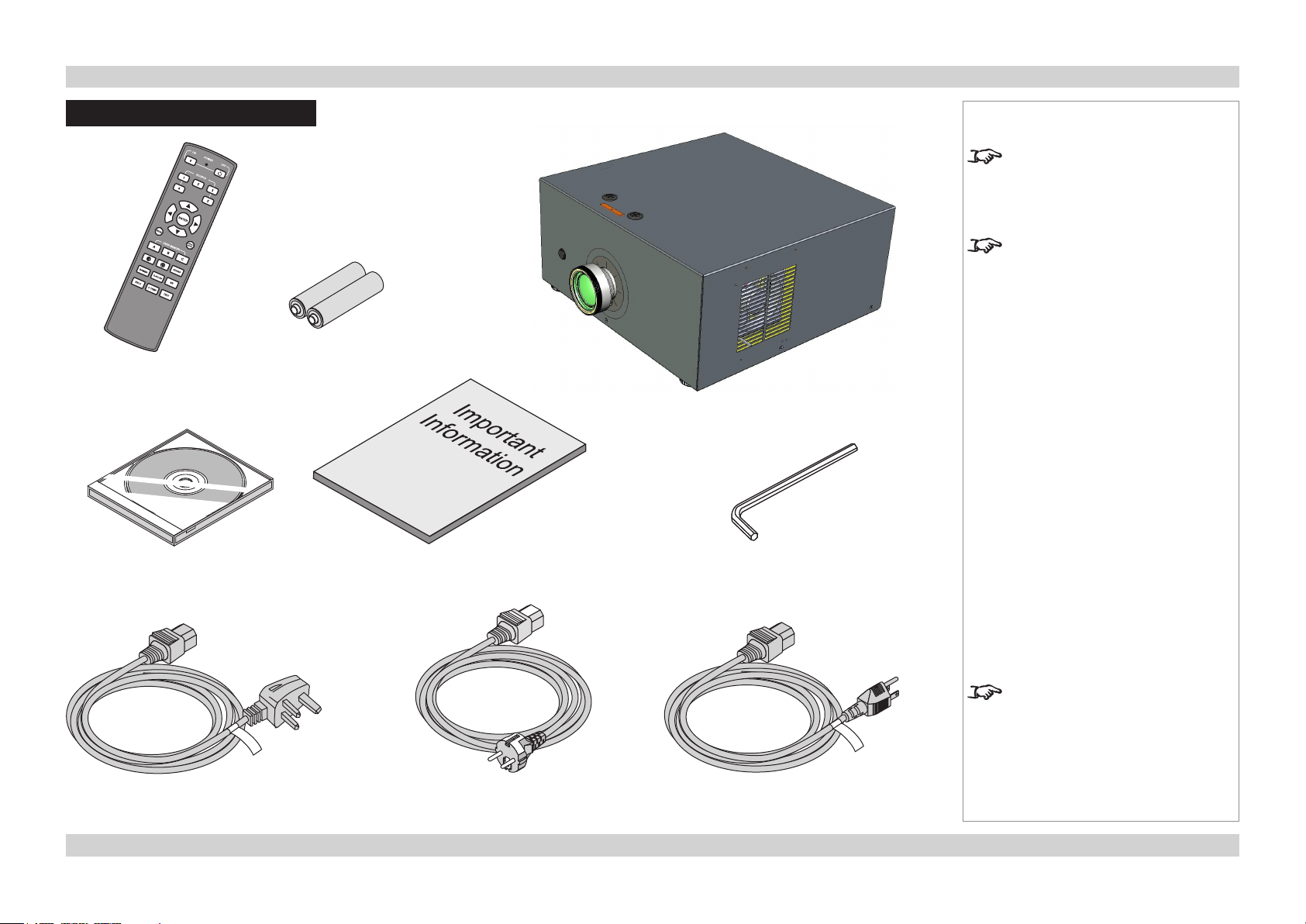
What’s in the Box?
2x AAA batteries
Remote control
(109-685)
Notes
Make sure your box contains
everything listed. If any pieces are
missing, contact your dealer.
You should save the original box
and packing materials, in case you
ever need to ship your Projector.
Projector
User Manual on disc
(115-759)
Power cable 10A, United Kingdom
(102-180)
Important Information
(110-287)
Power cable 10A, Europe
(102-163)
5mm Allen wrench
Only one power cable - dependent
on the destination territory - will be
supplied with the projector.
Power cable 13A, North America
(102-165)
Page Inst_2Rev D July 2014
Page 6
Digital Projection M-Vision LED+IR series GETTING TO KNOW THE PROJECTOR Installation and Quick-Start Guide
Getting to Know the Projector
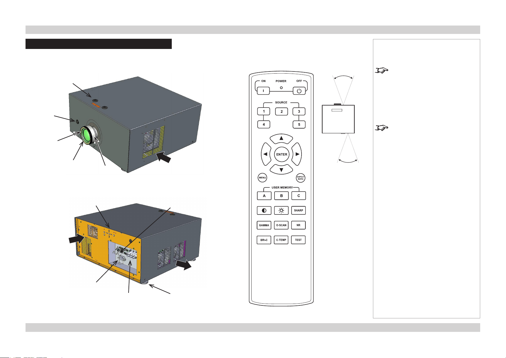
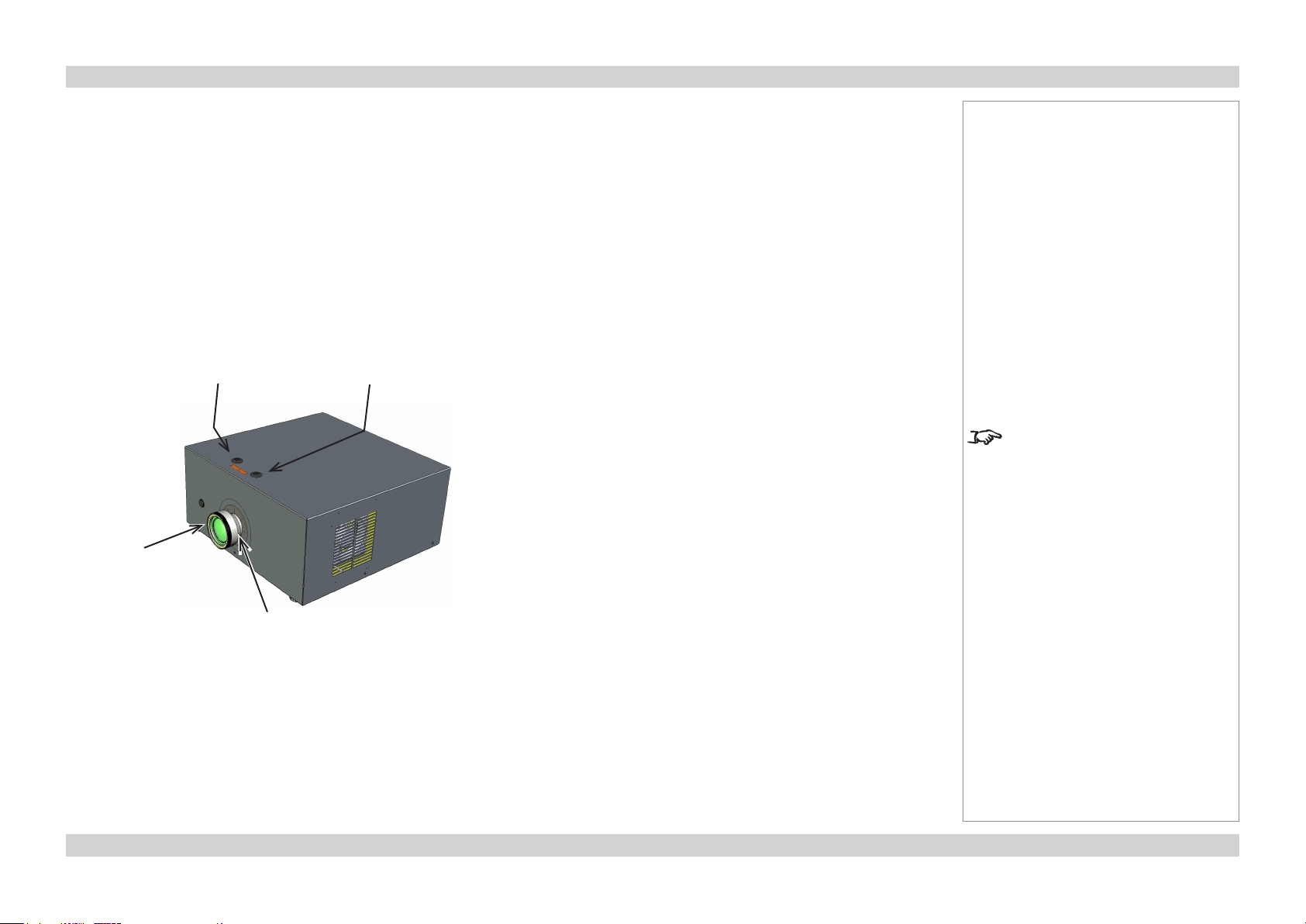
Front and rear views
Lens shift
controls
Front
infra-red
window
Focus
adjustment
Lens
Zoom
adjustment
Control
panel
Air
inlet
Rear
infra-red
window
Remote control
40°
40°
Infra-red
reception
Notes
The projector uses the standard
MVision series infra-red remote
control.
Some of the controls are duplicated
on the projector control panel, as
shown on the next page.
For full details of how to use the
controls and the menu system, see
the Operating Guide.
Air
inlets
Mains
input
Connection
panel
Air
outlets
Adjustable
feet
Page Inst_3Rev D July 2014
Page 7
Digital Projection M-Vision LED+IR series GETTING TO KNOW THE PROJECTOR Installation and Quick-Start Guide
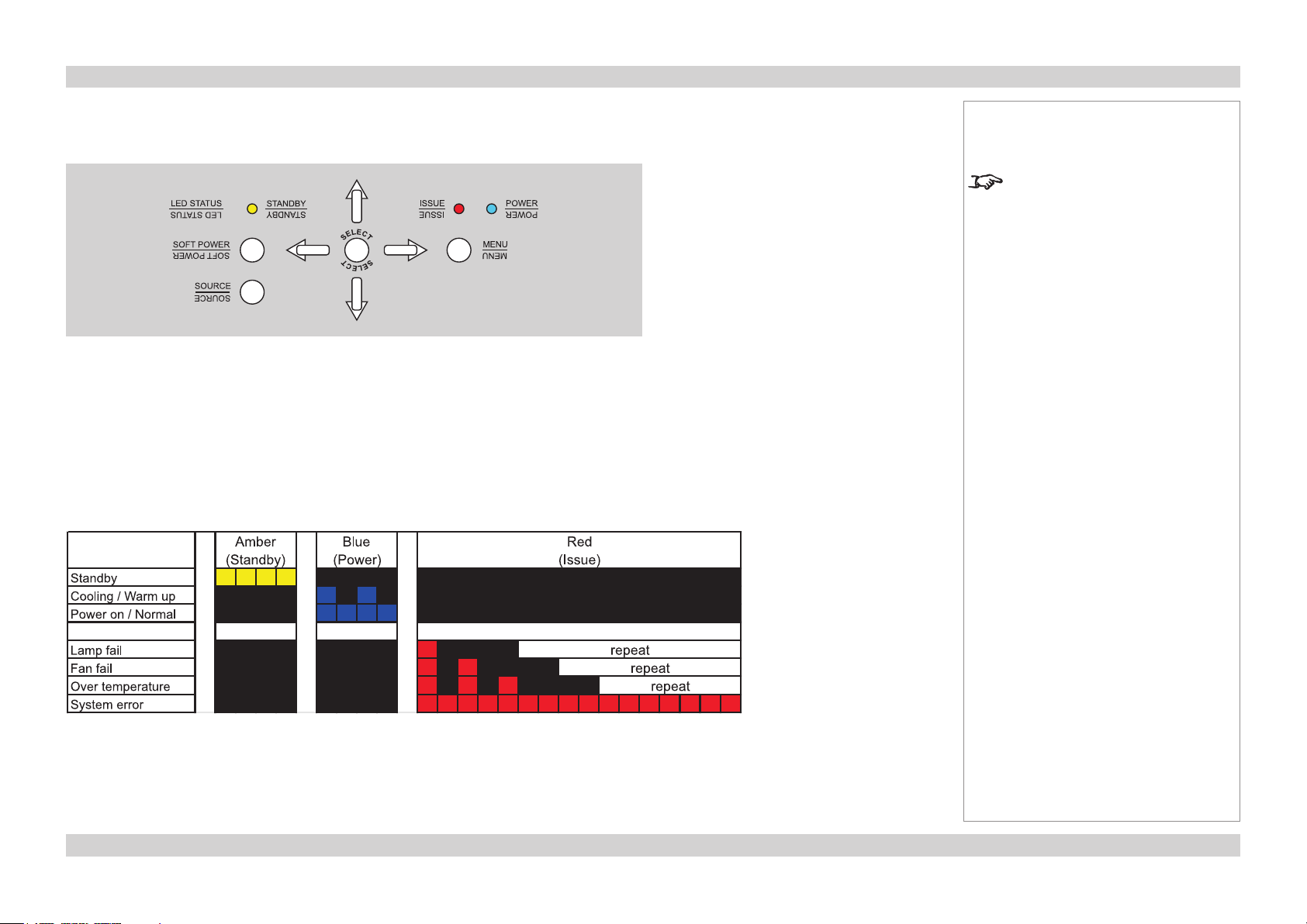
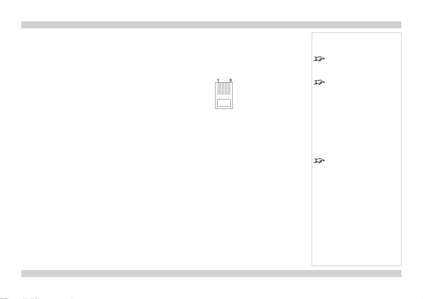
Control panel and indicators
Some of the controls from the remote control are duplicated on the projector control panel, as
shown here.
The yellow Standby indicator will light when the projector is in standby. The blue Power
indicator will ash when the projector is cooling down or warming up. It will be steady when
the projector is in normal running mode, as shown in the chart below.
Error codes
If the projector detects an error, the red Issue indicator will ash, as shown in the chart below.
For example, if the fan fails, the red indicator will ash twice followed by a pause, then the
sequence will repeat until the error condition is corrected.
Notes
For full details of how to use the
controls and the menu system, see
the Operating Guide.
Page Inst_4Rev D July 2014
Page 8
Digital Projection M-Vision LED+IR series POSITIONING THE SCREEN AND PROJECTOR Installation and Quick-Start Guide
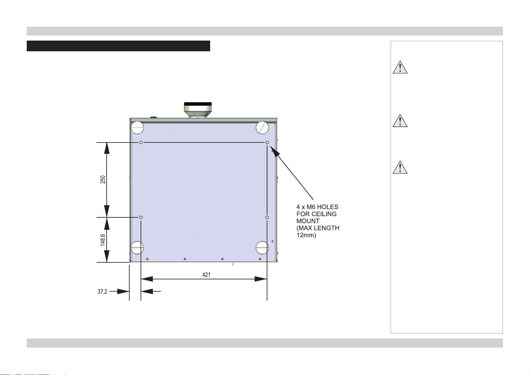
Positioning the Screen and Projector
• Install the screen, ensuring that it is in the best position for viewing by your audience.
• Mount the projector, ensuring that it is at a suitable distance from the screen for the image to ll the screen. Set the adjustable feet so that
the projector is level, and perpendicular to the sceen.
• The dimension drawing below shows the positions of the feet for table mounting, and the xing holes for ceiling mounting.
Notes
Always allow the lamp to cool for
5 minutes before:
- disconnecting the power
- moving the projector
Ensure that there is at least
30cm (12in) of space between the
ventilation outlets and any wall,
and 10cm (4in) on all other sides.
Do not stack more than 3
projectors.
Page Inst_5Rev D July 2014
Page 9
Digital Projection M-Vision LED+IR series OPERATING THE PROJECTOR Installation and Quick-Start Guide
Operating the Projector
Switching the Projector On
• Connect the power cable between the mains supply and the projector. Switch on at the switch next to the power connector.
• Wait until the self-test has completed and the Standby indicator on the projector control panel shows amber. The lamp will be off and the
projector will be in STANDBY mode.
• Press POWER on the control panel or on the remote control, and hold for 3 seconds.
The Power indicator on the control panel will ash blue for a few seconds whilst the lamp comes up to full brightness. When the projector
is ready for use, the Power indicator will show steady blue.
Selecting an Input Signal or Test Pattern
Input signal
• Connect an image source to the projector. The signal should be automatically detected by the projector, and should be displayed within a
two or three seconds.
• If more than one signal is connected, then select the image you want to display:
Select from ve of the inputs using to on the remote control,
or press SOURCE on the control panel to cycle through all the inputs.
or use Source Select in the General menu.
Notes
Always allow the lamp to cool for
5 minutes before:
- disconnecting the power
- moving the projector
For full details of how to connect an
image source to the projector, see
the Connection Guide.
For full details of how to use the
controls and the menu system, see
the Operating Guide.
Test patter n
If you have no image source connected to the projector, then you can display a test pattern instead:
Select a Test Patter n from the General menu.
Page Inst_6Rev D July 2014
Page 10
Digital Projection M-Vision LED+IR series OPERATING THE PROJECTOR Installation and Quick-Start Guide
Adjusting the Lens
Zoom
• Turn the smooth ring on the lens, closest to the case, to adjust the zoom so that the image lls the screen.
Focus
• Turn the knurled ring at the outer end of the lens, to adjust the focus until the image is sharp.
Shift
• Use the 5mm allen wrench to adjust the horizontal and vertical position of the image.
Horizontal
shift
Focus
adjustment
Vertical
shift
Notes
Iftheprojectoristtedwiththexed
0.73:1 lens then there are no lens
shift controls.
Zoom
adjustment
Page Inst_7Rev D July 2014
Page 11
Digital Projection M-Vision LED+IR series OPERATING THE PROJECTOR Installation and Quick-Start Guide
Adjusting the Image
Orientation
• Use the Rear Projection and Ceiling Mode settings, in the Setup Menu.
Aspect Ratio
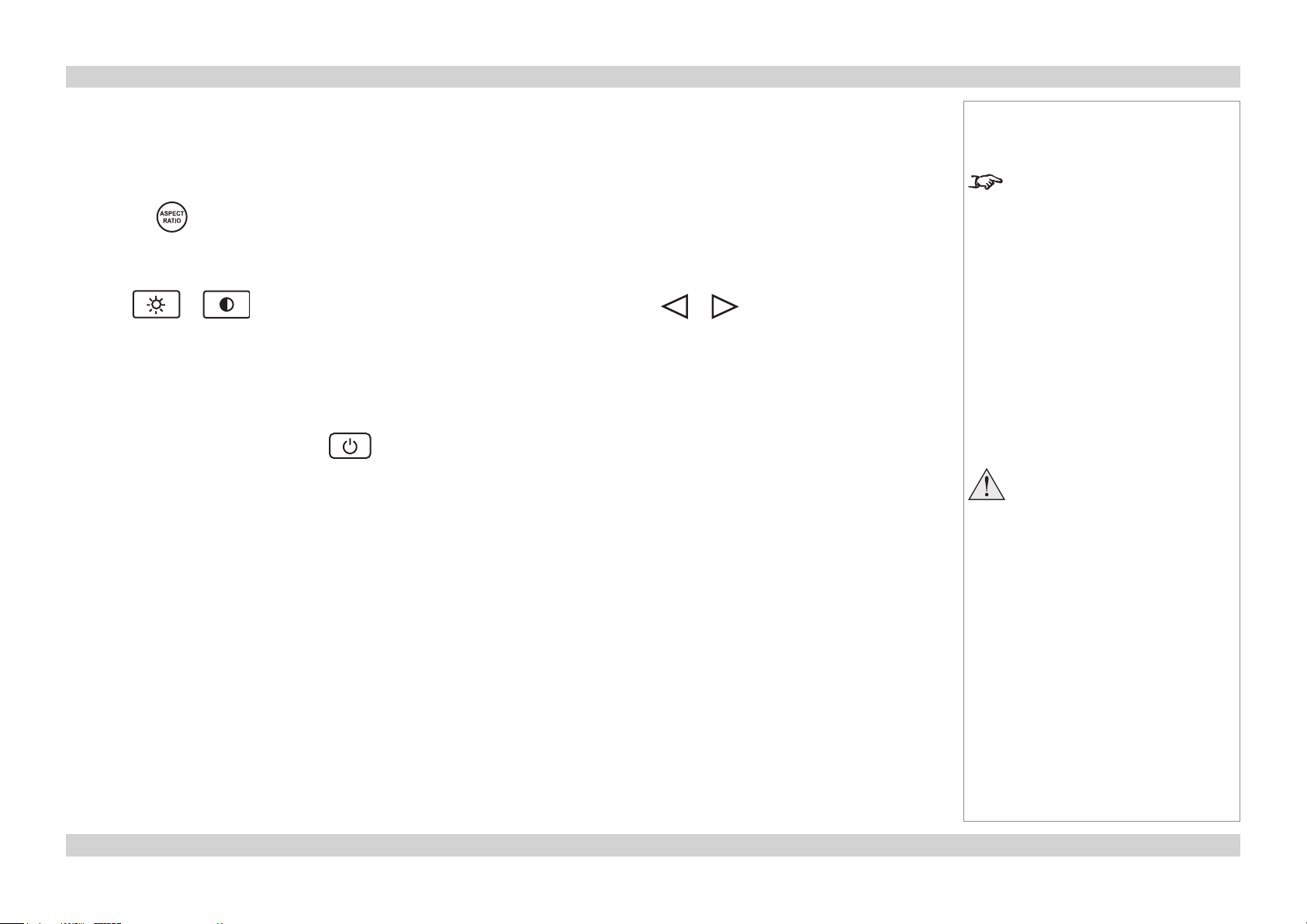
• Press the button on the remote control to cycle through all the available settings.
or use the Aspect Ratio setting in the Image Menu.
Picture
• Press or on the remote control to set the Brightness and Contrast, using or to adjust the sliders.
or use the Brightness or Contrast settings in the Image Menu.
Switching the Projector Off
• Press POWER on the control panel or on the remote control, then press the button a second time to conrm your intention to
switch off.
The lamp will go off, the Standby indicator on the control panel will show amber and the projector will be in Standby mode.
• Switch off at the switch next to the power connector. Disconnect the power cable from the projector.
Notes
For full details of how to use the
controls and the menu system, see
the Operating Guide.
Always allow the lamp to cool for
5 minutes before:
- disconnecting the power
- moving the projector
Page Inst_8Rev D July 2014
Page 12

M-Vision LED+IR series
High Brightness Digital Video Projector
16:10 widescreen display
CONNECTION GUIDE
Rev D July 2014
112-159D
Page 13

Digital Projection M-Vision LED+IR series CONTENTS Connection Guide
CONTENTS
About this Guide ................................................................................ Conn_1
Symbols used in this guide ............................................................... Conn_1
Warnings ....................................................................................Conn_1
Notes .......................................................................................... Conn_1
Product revision ................................................................................. Conn_1
Signal Inputs and Outputs .......................................................... Conn_2
HDMI 1 and 2 ....................................................................................... Conn_2
RGB .....................................................................................................Conn_2
S-Video ................................................................................................ Conn_2
Composite Video ................................................................................ Conn_2
Component 1 and 2 ............................................................................ Conn_2
SCART ................................................................................................. Conn_2
Supported Signal Input Modes................................................. Conn_3
Control Connections ....................................................................... Conn_5
Wired Remote Control .......................................................................Conn_5
LAN ...................................................................................................... Conn_5
RS232 ..................................................................................................Conn_5
Wiring Details....................................................................................... Conn_6
Signal inputs ....................................................................................... Conn_6
HDMI .......................................................................................... Conn_6
RGB ...........................................................................................Conn_7
S-Video ......................................................................................Conn_7
Composite Video ........................................................................ Conn_7
Component 1..............................................................................Conn_8
Component 2..............................................................................Conn_8
SCART .......................................................................................Conn_8
Control connections ..........................................................................Conn_9
Wired Remote control connection .............................................. Conn_9
Serial control input and output ................................................... Conn_9
LAN connection ........................................................................ Conn_10
Setting the LAN IP conguration .............................................. Conn_11
Rev D July 2014
Page 14

Digital Projection M-Vision LED+IR series ABOUT THIS GUIDE Connection Guide
About this Guide
Please read this guide carefully before using the projector, and keep it handy for future reference.
A serial number is located on the side of the projector. Record it here:
Symbols used in this guide
Warnings
ELECTRICAL WARNING: this symbol indicates that there is a danger of electrical shock unless the instructions are closely
followed.
WARNING: this symbol indicates that there is a danger of physical injury to yourself and/or damage to the equipment unless
the instructions are closely followed.
Notes
NOTE: this symbol indicates that there is some important information that you should read.
Product revision
Because we at Digital Projection continually strive to improve our products, we may change specications and designs, and add new features
without prior notice. Projectors built prior to this revision of the Operating Guide may therefore not include all the features described.
Page Conn_1Rev D July 2014
Page 15
Digital Projection M-Vision LED+IR series SIGNAL INPUTS AND OUTPUTS Connection Guide
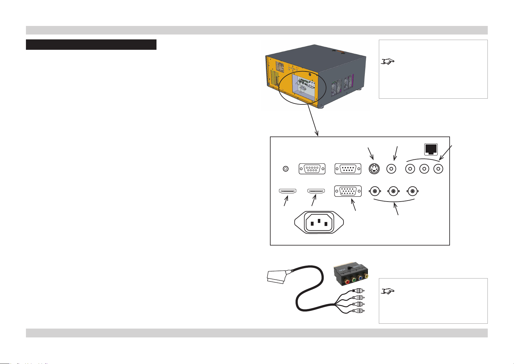
Signal Inputs and Outputs
HDMI 1 and 2
• Connect to either of the 4-pin HDMI connectors.
RGB
• Set Color Space in the Advanced menu to Auto, or RGB PC if necessary.
S-Video
• Connect to the 4-pin mini-DIN connector.
Composite Video
• Connect to the single Video phono connector.
Component 1 and 2
YPbPr/YCbCr
• Connect to Component 1 or Component 2.
• Set Color Space in the Advanced menu to Auto, or REC709 or REC601 if necessary.
RGsB
• Connect to Component 1 or Component 2.
• Set Color Space in the Advanced menu to Auto, or RGB Video if necessary.
HDMI 1
HDMI 2
S-Video
RGB
Notes
For a complete listing of pin
congurationsforallsignaland
control connectors, see Wiring
Details later in this Guide.
Video
Component
2
Component 1/
SCART
RGBS
• Connect the RGB cables to Component 1, and the Sync cable to Video.
• Select SCART in the Source Select menu.
SCART
• Using a SCART to RGBS adaptor, connect the RGB cables to Component 1, and the
Sync cable to Video.
• Select SCART in the Source Select menu.
When the SCART input is enabled,
the Video and Component 1 inputs
will be disabled.
SCART adaptors
Page Conn_2Rev D July 2014
Page 16

Digital Projection M-Vision LED+IR series SUPPORTED SIGNAL INPUT MODES Connection Guide
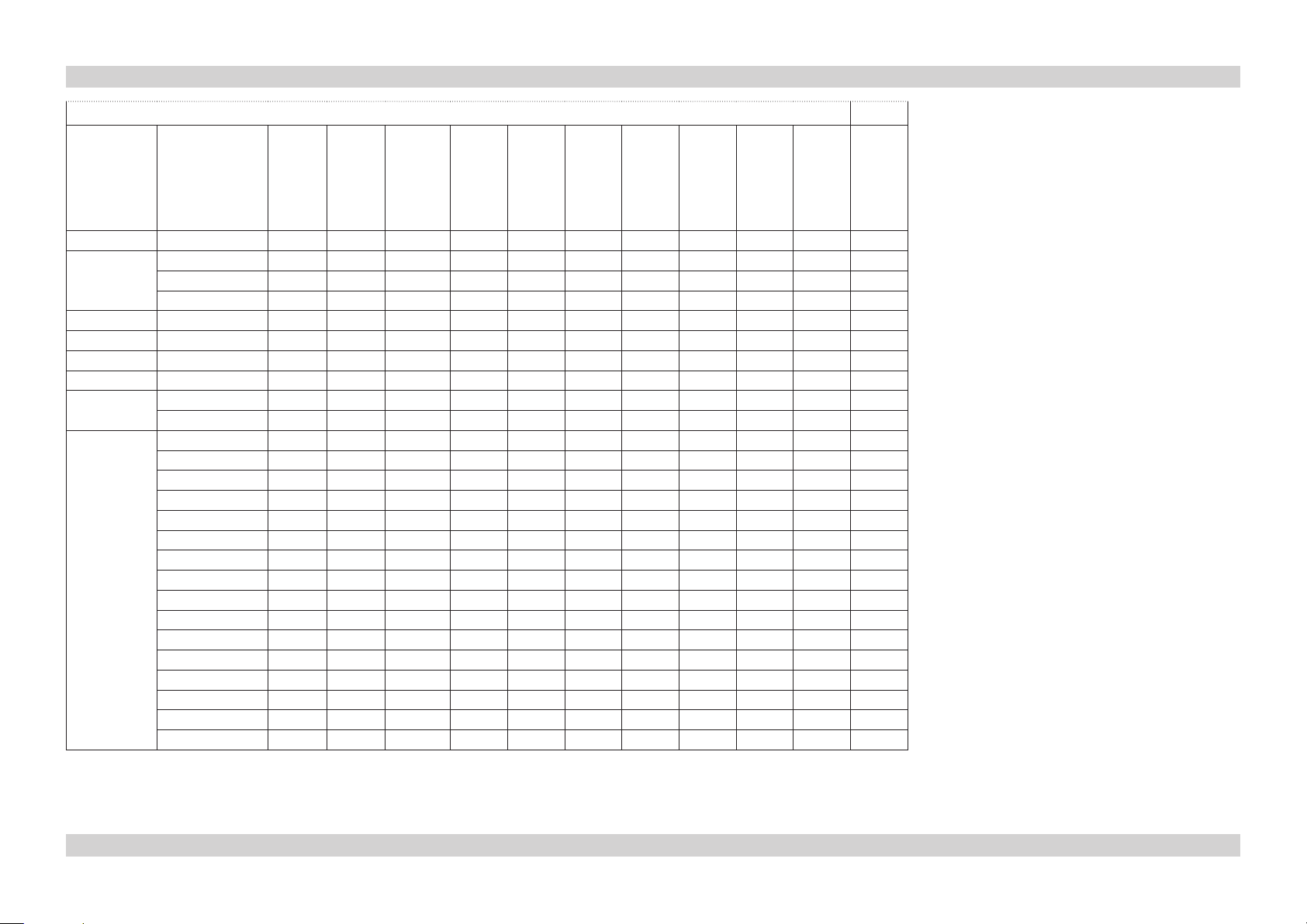
Supported Signal Input Modes
Signal Resolution Frame
Rate
( Hz )
PC 640 x 480 59.94
640 x 480 74.99
640 x 480 85
800 x 600 60.32
800 x 600 75
800 x 600 85.06
848 x 480 47.95
848 x 480 59.94
1024 x 768 60
1024 x 768 75.03
1024 x 768 85.03
1024 x 1024 59.92
1024 x 1024 59.999
1024 x 1024 60
1280 x 720 47.95
1280 x 1024 60.02
1280 x 1024 75.02
1280 x 1024 85.02
1400 x 1050 60
1600 x 900 60
1600 x 1200 60
1920 x 1080 47.95
1680 x 1050 59.94
1920 x 1200 60
Apple Mac 640 x 480 66.59
VIDEO
S-VIDEO
continued on next page...
SCART
COMPONENT
RGB (RGBHV)
RGB (RGsB)
ü ü
ü ü
ü ü
ü ü ü
ü ü
ü ü
ü ü
ü ü
ü ü
ü ü
ü ü
ü ü ü
ü ü
ü ü
ü ü
ü ü ü
ü ü ü
ü ü
ü ü ü
ü ü ü
ü ü
ü ü
ü ü
ü ü
ü ü
HDMI RGB
HDMI YUV 8 bit
HDMI YUV 10 bit
HDMI YUV 12 bit
Page Conn_3Rev D July 2014
Page 17
Digital Projection M-Vision LED+IR series SUPPORTED SIGNAL INPUT MODES Connection Guide
...continued from previous page
Signal Resolution Refresh
Rate
( Hz )
NTSC NTSC (M, 4.43) 59.94
PAL PAL (B,G,H,I) 50
PAL (N) 50
PAL (M) 59.94
SECAM SECAM (M) 50
SDTV RGBS 50
480i 59.94
576i 50
EDTV 480p 59.94
576p 50
HDTV 1035i 60
1080i 50
1080i (Aus) 50
1080i 59.94
1080i 60
720p 50
720p 59.94
720p 60
1080p 23.98
1080p 24
1080p 25
1080p 29.97
1080p 30
1080p 50
1080p 59.94
1080p 60
VIDEO
ü ü
ü ü
ü ü
ü ü
ü ü
S-VIDEO
SCART
ü
COMPONENT
RGB (RGBHV)
RGB (RGsB)
HDMI RGB
HDMI YUV 8 bit
HDMI YUV 10 bit
ü
ü
ü ü ü ü ü ü ü
ü ü ü ü ü ü ü
ü ü ü ü ü ü ü
ü ü ü ü ü ü ü
ü ü ü ü ü ü ü
ü ü ü ü ü ü ü
ü ü ü ü ü ü ü
ü ü ü ü ü ü ü
ü ü ü ü ü ü ü
ü ü ü ü ü ü ü
ü ü ü ü ü ü ü
ü ü ü ü ü ü ü
ü ü ü ü ü ü ü
ü ü ü ü ü ü ü
ü ü ü ü ü ü ü
ü ü ü ü ü ü ü
HDMI YUV 12 bit
Page Conn_4Rev D July 2014
Page 18

Digital Projection M-Vision LED+IR series CONTROL CONNECTIONS Connection Guide
Control Connections
Wired Remote Control
• If infrared signals from the remote control cannot reach the projector due to excessive
distance or obstructions such as walls or cabinet doors, you can connect an external
IR repeater to the Remote control input, and position its IR sensor within range of the
operator.
Note that plugging in the remote control cable will disable the infra-red.
LAN
• All of the projector’s features can be controlled via a LAN connection, using the text
strings described in the Remote Communications Guide.
• The default LAN IP address is 192.168.0.100. For information about how to change this,
see Setting the LAN IP conguration, later in this guide.
Each projector can be given a unique System ID, and this can be be used to control
them individually or simultaneously. For more information about this, see the Remote
Communications Guide.
Wired
Remote
RS232
IN
RS232
OUT
Notes
For a complete listing of pin
congurationsforallsignaland
control connectors, see Wiring
Details later in this Guide.
Only one remote connection should
be used at any one time.
LAN
RS232
• All of the projector’s features can be controlled via a serial connection, using the control
strings described in the Remote Communications Guide.
• Projectors can be connected in a daisy chain, connecting the RS232 OUT of one
projector to the RS232 IN of the next. Each projector can be given a unique System
ID, and this can be be used to control them individually or simultaneously. For more
information about this, see the Remote Communications Guide.
RS232
IN
OUT
IN
OUT
IN
OUT
Page Conn_5Rev D July 2014
Page 19

Digital Projection M-Vision LED+IR series WIRING DETAILS Connection Guide
Wiring Details
Signal inputs
HDMI
19 way type A connector
1 TMDS Data 2+
2 TMDS Data 2 Shield
3 TMDS Data 2-
4 TMDS Data 1+
5 TMDS Data 1 Shield
6 TMDS Data 1-
7 TMDS Data 0+
8 TMDS Data 0 Shield
9 TMDS Data 0-
10 TMDS Clock+
11 TMDS Clock Shield
12 TMDS Clock-
13 CEC
14 not connected
15 SCL (DDC Clock)
16 SCA (DDC Data)
17 DDC/CEC Ground
18 +5 V Power
19 Hot Plug Detect
Notes
For full details of all input settings,
see the Advanced menu in the
Operating Guide.
pin view of panel connector
Page Conn_6Rev D July 2014
Page 20
Digital Projection M-Vision LED+IR series WIRING DETAILS Connection Guide
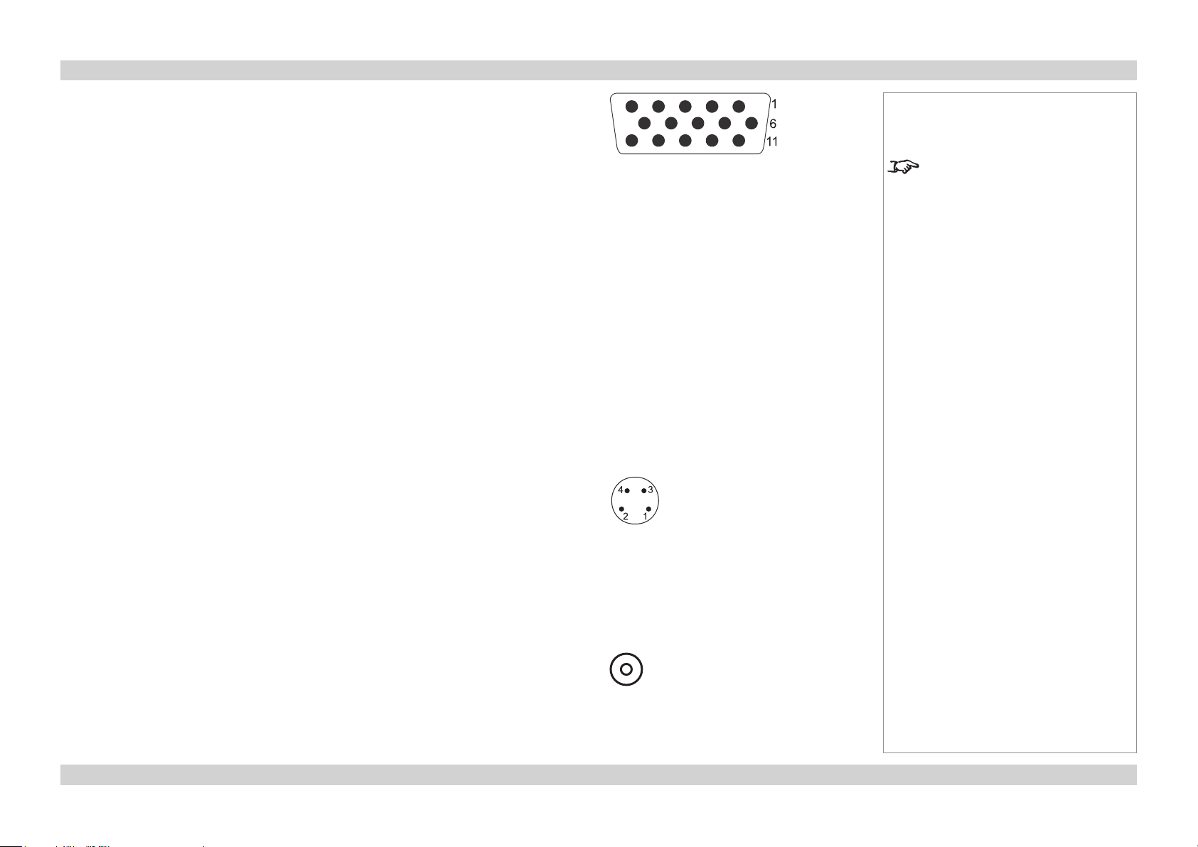
RGB
15 way D-type connector
1 R
2 G
3 B
4 unused
5 Digital Ground (H Sync)
6 R Ground
7 B Ground
8 G Ground
9 +5v
10 Digital Ground (V Sync/DDC)
11 unused
12 SDA
13 H Sync
14 V Sync
15 SCL
S-Video
4 pin mini-DIN
1 Y Ground
2 C Ground
3 Luminance (Y)
4 Chrominance (C)
pin view of female connector
pin view of female connector
Notes
For full details of all input settings,
see the Advanced menu in the
Operating Guide.
Composite Video
RCA Phono
Page Conn_7Rev D July 2014
Page 21

Digital Projection M-Vision LED+IR series WIRING DETAILS Connection Guide
Component 1
3 x RCA Phono connector
Component 2
3 x 75 ohm BNC
RGsB YCbCr YPbPr
R Cr Pr
G + Sync Y Y
B Cb Pb
RGBS
connect Sync to Video input
SCART
Using a SCART to RGBS adaptor, connect the RGB cables to Component 1, and the Sync
cable to Composite Video.
5 Blue ground
7 Blue
9 Green ground
11 Green
13 Red ground
15 Red
17 Sync ground
20 Sync
21 Chassis ground
Notes
For full details of all input settings,
see the Advanced menu in the
Operating Guide.
pin view of female connector
Page Conn_8Rev D July 2014
Page 22

Digital Projection M-Vision LED+IR series WIRING DETAILS Connection Guide
Control connections
Wired Remote control connection
3.5mm mini jack
Tip Signal
Ring Not connected
Sleeve Ground
Serial control input and output
1 unused
2 Received Data (RX)
3 Transmitted Data (TX)
4 unused
5 Signal Ground
6 unused
7 unused
8 unused
9 unused
Null-modem cable
(used to connect the projector to a computer)
RX 2 --- 3 TX
TX 3 --- 2 RX
GND 5 --- 5 GND
Serial port settings
Baud rate 38,400 bps
Data length 8 bits
Stop bits one
Parity none
Flow control none
Tip
Sleeve
Ring
pin view of female connector (IN)
pin view of male connector (OUT)
Notes
Note that plugging in the remote
control cable will disable the infrared.
Only one remote connection should
be used at any one time.
The projector is a DTE, so use:
a straight cable to connect to a
modem, or
a null-modem cable as shown here
to connect to another DTE such as a
computer.
Page Conn_9Rev D July 2014
Page 23
Digital Projection M-Vision LED+IR series WIRING DETAILS Connection Guide
LAN connection
TCP Port number
5450
10BaseT Unshielded Twisted Pair cable
The standard wire colours as as follows:
1 White / Orange stripe
2 Orange
3 White / Green stripe
4 Blue
5 White / Blue stripe
6 Green
7 White / Brown stripe
8 Brown
Crossed cable
(used to connect directly to a computer with no hub or network.)
(Note that only the green and orange pairs are crossed)
1 White / Orange stripe White / Green stripe 1
2 Orange Green 2
3 White / Green stripe White / Orange stripe 3
4 Blue Blue 4
5 White / Blue stripe White / Blue stripe 5
6 Green Orange 6
7 White / Brown stripe White / Brown stripe 7
8 Brown Brown 8
Notes
Only one remote connection should
be used at any one time.
For information about how to set the
LANIPconguration,seethenext
page.
top view of cable
connector
(clip is underneath)
Use:
a straight cable to connect to a hub
or network, or
a crossed cable as shown here
to connect ONLY to a computer
directly.
Page Conn_10Rev D July 2014
Page 24

Digital Projection M-Vision LED+IR series WIRING DETAILS Connection Guide
Setting the LAN IP conguration
• Point your browser at the projector by typing its LAN IP Address into the address bar,
then press the Enter key.
• The embedded IP Conguration webpage should appear.
Notes
The default LAN IP address is
192.168.0.100
DO NOT change this unless it is
absolutely necessary.
Make sure you make a note of the
new address when you have done
so.
• Edit the settings as required, then click on Save.
Page Conn_11Rev D July 2014
Page 25

M-Vision LED+IR series
High Brightness Digital Video Projector
16:10 widescreen display
OPERATING GUIDE
Rev D July 2014
112-160D
Page 26

Digital Projection M-Vision LED+IR series CONTENTS Operating Guide
CONTENTS
About this Guide .................................................................................... Op_1
Symbols used in this guide ................................................................... Op_1
Warnings ........................................................................................ Op_1
Notes .............................................................................................. Op_1
Product revision ..................................................................................... Op_1
Using the Menus .................................................................................... Op_2
Navigating the menus ............................................................................ Op_2
Submenus ............................................................................................... Op_3
Sliders ..................................................................................................... Op_3
Selecting parameters ............................................................................. Op_4
Commands .............................................................................................. Op_5
A Tour of the Menus ............................................................................ Op_6
General Menu.......................................................................................... Op_6
Source Select ................................................................................. Op_6
Menu Position ................................................................................ Op_6
Memory .......................................................................................... Op_6
Blank Screen .................................................................................. Op_7
Logo Display .................................................................................. Op_7
Auto-Source ................................................................................... Op_7
Test Patterns .................................................................................. Op_7
Blue Only........................................................................................ Op_7
Image Menu............................................................................................. Op_8
Aspect Ratio ................................................................................... Op_8
Brightness, Contrast, Color Saturation, Color Tint ....................... Op_10
Sharpness .................................................................................... Op_10
Noise Reduction ........................................................................... Op_11
Overscan ...................................................................................... Op_11
Hue/Saturation/Gain..................................................................... Op_12
Resync ......................................................................................... Op_12
Horizontal and Vertical Shift ......................................................... Op_12
Advanced Menu .................................................................................... Op_13
Color Space ................................................................................. Op_13
Video Standard and DLP Frame Rate ......................................... Op_13
Gamma, Color Temperature and Color Gamut ............................ Op_13
Brilliant Color® and Adaptive Contrast ......................................... Op_13
RGB Adjust................................................................................... Op_14
Fine Sync .................................................................................... Op_14
Setup Menu ........................................................................................... Op_15
Lighting Mode............................................................................... Op_15
Anti-Blur ....................................................................................... Op_15
Auto Power Off ............................................................................. Op_15
Auto Power On ............................................................................. Op_15
Rear Projection ............................................................................ Op_16
Ceiling Mode ................................................................................ Op_16
Source Enable.............................................................................. Op_16
Altitude ......................................................................................... Op_16
Info Menu .............................................................................................. Op_17
Information ................................................................................... Op_17
LED Hour Reset ........................................................................... Op_17
Factory Reset ............................................................................... Op_17
Menu Map ................................................................................................. Op_18
GENERAL .............................................................................................. Op_18
IMAGE.................................................................................................... Op_18
ADVANCED ........................................................................................... Op_19
SETUP ................................................................................................... Op_19
INFORMATION ...................................................................................... Op_19
Rev D July 2014
Page 27

Digital Projection M-Vision LED+IR series ABOUT THIS GUIDE Operating Guide
About this Guide
Please read this guide carefully before using the projector, and keep it handy for future reference.
A serial number is located on the side of the projector. Record it here:
Symbols used in this guide
Warnings
ELECTRICAL WARNING: this symbol indicates that there is a danger of electrical shock unless the instructions are closely
followed.
WARNING: this symbol indicates that there is a danger of physical injury to yourself and/or damage to the equipment unless
the instructions are closely followed.
Notes
NOTE: this symbol indicates that there is some important information that you should read.
Product revision
Because we at Digital Projection continually strive to improve our products, we may change specications and designs, and add new features
without prior notice. Projectors built prior to this revision of the Operating Guide may therefore not include all the features described.
Page Op_1Rev D July 2014
Page 28

Digital Projection M-Vision LED+IR series USING THE MENUS Operating Guide
Using the Menus
Use the buttons on the projector control
panel or on the remote control, to access the
menu system.
• To open or close the on-screen display
(OSD), press MENU.
(When closing the OSD, you may need
to press MENU more than once if any
sub-menus are open.)
Navigating the menus
• Select a menu using
and ,
• then open the menu by pressing
ENTER/SELECT.
The rst item in the menu is highlighted.
Projector control panel
Notes
Some menu options and controls
may not be available due to settings
in other menus. These will be
shaded green on the actual menu.
Remote control
• Select an item in the menu using
and .
• To open another menu, rst close the
current menu by pressing MENU.
Page Op_2Rev D July 2014
Page 29

Digital Projection M-Vision LED+IR series USING THE MENUS Operating Guide
Submenus
• Select a submenu using
and .
• then press ENTER/SELECT.
• The submenu opens, with the rst item
highlighted.
• To close the submenu, press MENU.
Sliders
• Activate the slider by pressing
or .
Notes
Some menu options and controls
may not be available due to settings
in other menus. These will be
shaded green on the actual menu.
• Use or to adjust the value.
• Press MENU or ENTER/SELECT to
accept the value.
Page Op_3Rev D July 2014
Page 30

Digital Projection M-Vision LED+IR series USING THE MENUS Operating Guide
Selecting parameters
Most parameters are changed by selecting
from a list:
• Select from the list using
and .
• The change will be made immediately.
Some parameters are changed by selecting
from a submenu.
• Press ENTER/SELECT to open the
submenu.
• The item that is currently selected is
highlighted with a cross .
• Select from the list using
Notes
Some menu options and controls
may not be available due to settings
in other menus. These will be
shaded green on the actual menu.
and .
• The change will be made when you
press ENTER/SELECT to conrm the
selection.
Page Op_4Rev D July 2014
Page 31

Digital Projection M-Vision LED+IR series USING THE MENUS Operating Guide
Commands
• To use a command, press ENTER/
SELECT.
• In this example,
use or to select YES or NO,
then press ENTER/SELECT to conrm
your selection.
Notes
Some menu options and controls
may not be available due to settings
in other menus. These will be
shaded green on the actual menu.
Page Op_5Rev D July 2014
Page 32

Digital Projection M-Vision LED+IR series A TOUR OF THE MENUS Operating Guide
A Tour of the Menus
General Menu
Source Select
• Select which input source to display.
Menu Position
• Set this to determine the position of the menus on the screen.
Notes
See also Using the Menus, earlier
in this guide and Menu Map, later in
this guide.
The input source that is currently
selected is highlighted with a
cross .
To use the SCART input, you
will need an adaptor. See the
Connection Guide for more
information.
Memory
• The current image settings can be saved to one of two Presets. Either of the two Presets or the Default settings, can be recalled later.
• The following settings are saved:
From the Image menu:
Aspect Ratio Brightness Contrast Saturation Tint
Sharpness Noise Reduction Overscan HSG
From the Advanced menu:
Color Space Video Standard Gamma Colour Temperature DLP Frame Rate
Color Gamut Brilliant Color Adaptive Contrast RGB Offsets RGB Gains
User-1 and User-2 can also be
recalled using the USER MEMORY
A and B keys on the remote control.
Note: Buttons C and D on the
remote control are not used.
When Save Presets is selected,
the image settings for ONLY the
selected input are saved.
Page Op_6Rev D July 2014
Page 33

Digital Projection M-Vision LED+IR series A TOUR OF THE MENUS Operating Guide
General Menu continued
Blank Screen
• Set this to determine what appears on screen when the projector is searching for a valid input source.
Logo Display
• Set this to determine whether the Digital Projection logo appears when the projector is switching from Stanby to On.
Auto-Source
• When this is set to On, the projector will search for an alternative input source when the current input source is disconnected
• When this is set to Off, the projector will show a ‘blank’ screen when the current input source is disconnected.
Test Patterns
• Select from a range of test patterns.
• Press MENU to return to the menu, or ENTER/SELECT to return to the currently selected input signal.
Notes
See also Using the Menus, earlier
in this guide and Menu Map, later in
this guide.
To set what a ‘blank’ screen looks
like, use the Blank Screen setting
in the System menu.
Blue Only
• Set this to On to display only the blue component of the input signal, for calibration or test purposes.
Page Op_7Rev D July 2014
Page 34

Digital Projection M-Vision LED+IR series A TOUR OF THE MENUS Operating Guide
Image Menu
Aspect Ratio
• Select from 16:10, 16:9, Letterbox, 4:3, 4:3 Narrow, Square and Native.
Examples
Notes
See also Using the Menus, earlier
in this guide and Menu Map, later in
this guide.
The Native image examples shown
here have far fewer pixels than
the 1920 x 1200 of the DMD. Your
image may be different.
16:10 image using Native setting 16:10 image using 16:10 setting
16:9 image using Native setting 16:9 image using 16:9 setting
When displaying a 16:10 or 16:9
image, DO NOT use an anamorphic
lens.
Page Op_8Rev D July 2014
Page 35

Digital Projection M-Vision LED+IR series A TOUR OF THE MENUS Operating Guide
Image Menu, Aspect Ratio examples continued
4:3 image using Native setting 4:3 image using 4:3 setting
2.35:1 image using 16:9 setting
without anamorphic lens
2.35:1 image using Letterbox setting
without anamorphic lens
4:3 image using 4:3 Narrow setting
without anamorphic lens
2.35:1 image using Letterbox setting
with anamorphic lens
4:3 image using 4:3 Narrow setting
with anamorphic lens
Notes
The Native image examples shown
here have far fewer pixels than
the 1920 x 1200 of the DMD. Your
image may be different.
An anamorphic lens is used with
the Letterbox setting, to ensure that
for a 2.35:1 image, the maximum
area of the DMD is used, giving
maximum image brightness.
When displaying a 16:10 or 16:9
image, DO NOT use an anamorphic
lens.
The 4:3 Narrow setting is used to
compensate for the distortion that an
anamorphic lens would cause to a
4:3 image.
Use the Square setting when
projecting onto a square screen,
and ONLY in applications where the
aspect ratio is not critical.
16:9 image using Square setting4:3 image using Square setting
Page Op_9Rev D July 2014
Page 36

Digital Projection M-Vision LED+IR series A TOUR OF THE MENUS Operating Guide
Image Menu continued
Brightness, Contrast, Color Saturation, Color Tint
• Adjust the sliders for these settings.
Sharpness
• Press ENTER/SELECT to open the Shapness sub-menu.
Notes
See also Using the Menus, earlier
in this guide and Menu Map, later in
this guide.
Image Menu
Sharpness submenu
The Advanced sliders will not be
available unless Advanced Mode is
chosen.
• In Simple mode, adjust the single Sharpness slider at the top of the menu, as required.
• If the simple mode adjustment is not effective then select Advanced mode, and adjust the advanced sliders as required:
• The Horizontal, Vertical and Diagonal Sharpness controls can be used to enhance image detail along edges.
• The Sharpness Overshoot control can be used to minimize or eliminate rings or shadows on dominant edges.
• The Horizontal, Vertical and Diagonal Texture, and Texture Overshoot controls can be used to remove artifacts from textured
areas.
• The Noise Threshold control can be used to adjust the noise threshold frequency. Frequencies above the threshold are considered
to be ‘noise’, and will not be sharpened.
Page Op_10Rev D July 2014
Page 37

Digital Projection M-Vision LED+IR series A TOUR OF THE MENUS Operating Guide
Image Menu continued
Noise Reduction
• Press ENTER/SELECT to open the Noise Reduction sub-menu.
• In Simple mode, adjust the single Noise Reduction slider at the top of the menu, as required.
• If the simple mode adjustment is not effective then select Advanced mode, and adjust the advanced sliders as required:
• General Noise Reduction can be used to detect differences from frame to frame, reducing those differences that are not
determined to be motion.
• Block Artifact Reduction can be used to reduce or eliminate distortion within horizontal and vertical block boundaries, particularly
in MPEG-compressed video signals.
• Mosquito Noise Reduction can be used to reduce or eliminate distortion around the edges of moving objects, moving artifacts
around edges and/or blotchy noise patterns superimposed over the objects, particularly in MPEG-compressed video signals.
Overscan
• Select from Off, Crop or Zoom.
Notes
See also Using the Menus, earlier
in this guide and Menu Map, later in
this guide.
Image Menu
Noise Reduction submenu
Overscan is used to compensate
fornoisyorbadlydenedimage
edges, by either:
- cropping the edges from the image
or
- increasing the size of the image, to
force the edges off-screen.
Page Op_11Rev D July 2014
Page 38

Digital Projection M-Vision LED+IR series A TOUR OF THE MENUS Operating Guide
Image Menu continued
Hue/Saturation/Gain
• Press ENTER/SELECT to open the Hue/Saturation/Gain sub-menu.
• Use the HSG Select control to select from Hue, Saturation and Gain.
Use the sliders to adjust the hue, saturation or gain of each colour as required.
Notes
See also Using the Menus, earlier
in this guide and Menu Map, later in
this guide.
Image Menu
HSG submenu
Resync
• Press ENTER/SELECT to force the projector to re-synchronise with the current input signal.
Horizontal and Vertical Shift
• Use the sliders to adjust the image position as required.
Page Op_12Rev D July 2014
Page 39

Digital Projection M-Vision LED+IR series A TOUR OF THE MENUS Operating Guide
Advanced Menu
Color Space
• Set this to Auto, except when the projector has problems selecting between REC709, REC601, REC601, RGB-PC and RGB-Video.
Video Standard and DLP Frame Rate
• Set this to Auto, except when the projector has problems recognising the video parameters.
Notes
See also Using the Menus, earlier
in this guide and Menu Map, later in
this guide.
Brilliant Color® allows for
increased projector brightness
and improved color saturation by
enabling the yellow segments on the
colour wheel.
Gamma, Color Temperature and Color Gamut
• Set this to suit the specication of the input source, or to improve the appearance of the projected image.
Brilliant Color® and Adaptive Contrast
• Set these to suit your brightness and contrast requirements.
Adaptive Contrast expands
the light and dark portions of
the contrast curve of the image,
depending on the mean luminance
of the image.
Setting either of these two
parameters to On will affect any
image quality settings made in other
menus.
Page Op_13Rev D July 2014
Page 40

Digital Projection M-Vision LED+IR series A TOUR OF THE MENUS Operating Guide
Advanced Menu continued
RGB Adjust
• Adjust the RGB offset and gain settings to improve the colour balance of the projected image.
Fine Sync
• Adjust these settings to suit the conguration of the input signal.
Notes
See also Using the Menus, earlier
in this guide and Menu Map, later in
this guide.
Image Menu
RGB Adjust submenu
RGB Adjust and Fine Sync affect
only RGB input sources.
Image Menu
Fine Sync submenu
Page Op_14Rev D July 2014
Page 41

Digital Projection M-Vision LED+IR series A TOUR OF THE MENUS Operating Guide
Setup Menu
Lighting Mode
• Set this to Daylight to set the projected output to RGB only.
• Set this to Night to set the projected output to Infra-Red only.
• Set this to Custom to enable the RGB Dimming and IR Dimming controls, for a combination of the two outputs.
Anti-Blur
• Select from Off, 10mS and 8mS.
Auto Power Off
• Set this to On, if you want the projector to go into Standby mode when no input source is detected for 20 minutes.
Notes
See also Using the Menus, earlier
in this guide and Menu Map, later in
this guide.
The Lighting Mode will not change
until the menu has been turned off.
Anti-Blur will increase the black
time between frames, to reduce
any blurring effect from fast moving
images.
Note: This will decrease the
perceived brightness of the image.
Auto Power On
• Set this to On, if you want the projector to start up imediately when the mains is connected.
• Set this to Off, if you want the projector to go into Standby mode when the mains is connected. In this case, the projector will not start up
until the POWER button is pressed on the control panel or the remote control.
Page Op_15Rev D July 2014
Page 42

Digital Projection M-Vision LED+IR series A TOUR OF THE MENUS Operating Guide
Advanced Menu continued
Rear Projection
• Set this to On to reverse the image from left to right, for use in Rear Projection Mode.
Ceiling Mode
• Set this to On to reverse the image from top to bottom, for use in Ceiling Mode.
Source Enable
• Press ENTER/SELECT to open the Source Enable sub-menu.
Use this to enable or disable any of the source inputs.
Altitude
• When this is set to Auto, the internal fan will operate at Low speed, and rise to High speed automatically if the internal temperature rises.
• When this is set to High, the fan will operate at High speed continuously, for use at high altitude locations.
Notes
See also Using the Menus, earlier
in this guide and Menu Map, later in
this guide.
When the SCART input is enabled,
the Video and Component 1 inputs
will be disabled.
To use the SCART input, you
will need an adaptor. See the
Connection Guide for more
information.
Page Op_16Rev D July 2014
Page 43

Digital Projection M-Vision LED+IR series A TOUR OF THE MENUS Operating Guide
Info Menu
Information
• The menu shows information about the projector and the currently selected input source.
• The System ID can be set to any number between 0 and 255.
Notes
See also Using the Menus, earlier
in this guide and Menu Map, later in
this guide.
To set the System ID:
- connect one projector at a time and
set each to a different number using
the op sysid command.
For more information about this, see
the Connections Guide and the
Remote Communications Guide.
LED Hour Reset
• Press ENTER/SELECT to reset the LED hour counter to zero.
Factory Reset
• Press ENTER/SELECT to restore all settings to their factory defaults.
• When the warning message appears, use or to select YES or NO, then press ENTER/SELECT to conrm your selection.
Do NOT do this unless you are
sure that you want to set the LED
hour counter to zero, eg if a new
LED module has been installed.
Do NOT do this unless you are
sure that you want to restore
ALL the current settings to their
factory defaults.
Page Op_17Rev D July 2014
Page 44

Digital Projection M-Vision LED+IR series MENU MAP Operating Guide
Menu Map
Menu Sub Menus and Controls
GENERAL
Source Select HDMI1, HDMI2, RGB, Component 1, Component 2, Video, S-Video, SCART
Menu Position Top Left, Top Right, Bottom Left, Bottom Right, Centre
Memory
Recall User 1, User 2, Default
Save User 1, User 2
Blank Screen Logo, Black, Blue, White
Logo Display On, Off
Auto Source On, Off
Test Patterns Off, White, Black, Red, Green, Blue, Cyan, Magenta, Yellow, Checkerboard, Vertical Burst, Hori-
zontal Burst
Blue Only Off, On
IMAGE
Aspect Ratio 16:10, 16:9, Letterbox, 4:3, 4:3 Narrow, Square, Native
Brightness
Contrast
Color Saturation
Colour Tint
Sharpness Simple, Advanced
Advanced Horizontal, Vertical Diagonal Sharpness, Sharpness Overshoot, Horizontal, Vertical Diagonal
Texture, Texture Overshoot, Noise Threshold
Noise Reduction Simple, Advanced
Advanced General, Block Artifact, Mosquito
Overscan Off, Crop, Zoom
HSG
Hue, Saturation, Gain: Red, Green, Blue, Cyan, Magenta, Yellow
Resync Projector will re-synchronise with the current input signal
Horizontal Shift
Vertical Shift
Notes
Some of the information in this menu
map is summarised. See the actual
menu on the projector for full detail.
Some menu options and controls
may not be available due to settings
in other menus. These will be
shaded green on the actual menu.
Where it would be helpful, some
menu options are described in more
detail earlier in this operating guide.
Page Op_18Rev D July 2014
Page 45

Digital Projection M-Vision LED+IR series MENU MAP Operating Guide
Menu Sub Menus and Controls
ADVANCED
Color Space Auto, REC709, REC601, RGB PC, RGB Video
Video Standard Auto, NTSC, PAL, SECAM
Gamma Film, Cinema, Bright, Graphics, CRT
Color Temperature Custom, 6500K
DLP Frame Rate Auto, 48Hz, 50Hz, 60Hz
Color Gamut (not available)
BrilliantColor On, Off
Adaptive Contrast On, Off
RGB Adjust RGB Offset and Gain
Fine Sync V Position, H Position, Phase, Tracking, Sync Level
SETUP
Lighting Mode Daylight, Night, Custom
Custom RGB Dimming, IR Dimming
Anti-Blur Off, 10mS, 8mS
Remote Control On, Off
Auto Power Off On, Off
Auto Power On On, Off
Rear Projection Off, On
Ceiling Mode Off, On
Source Enable all available inputs
Altitude Auto, High Altitude
Notes
Some of the information in this menu
map is summarised. See the actual
menu on the projector for full detail.
Some menu options and controls
may not be available due to settings
in other menus. These will be
shaded green on the actual menu.
Where it would be helpful, some
menu options are described in more
detail earlier in this operating guide.
INFORMATION
Information Model Name, Serial Number, Software Version, Active Source, Pixel Clock, Signal Format,
H⁄VRefreshRate,LEDHours
LED Hours reset ProjectorwillaskforconrmationbeforetheLEDhourcountertozero
Factory Reset Projectorwillaskforconrmationbeforerestoringallsettingstofactorydefaults
Information System ID
Page Op_19Rev D July 2014
Page 46

REMOTE COMMUNICATIONS GUIDE
M-Vision LED+IR series
High Brightness Digital Video Projector
16:10 widescreen display
Rev D July 2014
112-161D
Page 47

Digital Projection M-Vision LED+IR series CONTENTS Remote Communications Guide
CONTENTS
About this Guide ................................................................................. Rem_1
Symbols used in this guide ................................................................ Rem_1
Warnings ..................................................................................... Rem_1
Notes ........................................................................................... Rem_1
Product revision .................................................................................. Rem_1
Introduction ........................................................................................... Rem_2
Command format ................................................................................. Rem_2
Prex code .................................................................................. Rem_2
Examples .................................................................................... Rem_2
The Key Commands.......................................................................... Rem_3
Examples .................................................................................... Rem_3
The Operation Commands ........................................................... Rem_5
Examples .................................................................................... Rem_5
General menu ...................................................................................... Rem_6
Image menu ......................................................................................... Rem_6
Advanced menu................................................................................... Rem_7
Setup menu .......................................................................................... Rem_8
Information menu ................................................................................ Rem_8
Miscellaneous commands .................................................................. Rem_9
Rev D July 2014
Page 48

Digital Projection M-Vision LED+IR series ABOUT THIS GUIDE Remote Communications Guide
About this Guide
Please read this guide carefully before using the projector, and keep it handy for future reference.
A serial number is located on the side of the projector. Record it here:
Symbols used in this guide
Warnings
ELECTRICAL WARNING: this symbol indicates that there is a danger of electrical shock unless the instructions are closely
followed.
WARNING: this symbol indicates that there is a danger of physical injury to yourself and/or damage to the equipment unless
the instructions are closely followed.
Notes
NOTE: this symbol indicates that there is some important information that you should read.
Product revision
Because we at Digital Projection continually strive to improve our products, we may change specications and designs, and add new features
without prior notice. Projectors built prior to this revision of the Operating Guide may therefore not include all the features described.
Page Rem_1Rev D July 2014
Page 49

Digital Projection M-Vision LED+IR series INTRODUCTION Remote Communications Guide
Introduction
The projector can be controlled by using an external control system or a computer via a LAN or an RS232 serial interface, using a terminalemulation program, such as HyperTerminal.
Projectors can be connected in a daisy chain, connecting the RS232 OUT of one projector to the RS232 IN of the next. Each projector can be
given a unique System ID, and they can be controlled individually or simultaneously via a single computer.
Command format
There are 2 types of command, Key commands and Operation commands. The individual commands are described later in this guide. All
commands consist of ascii text strings ending with an ascii carriage return character. If a number of projectors are connected in a daisy chain,
then each command should be preceded by a prex code. For a single projector, a prex code should NOT be used.
• Key commands: <prex code> ky <keyname> [CR]
• Operation commands: <prex code> op <operation> <command> [CR]
Prex code
The prex code, if used, comprises the rst four bytes of the command, and is made up of the following bytes (in hex):
byte 0 DE (an unprintable character)
byte 1 C0 (an unprintable character)
byte 2 ID1 (ASCI character representing the rst half of the projector’s System ID in hex)
byte 3 ID2 (ASCI character representing the second half of the projector’s System ID in hex)
Examples
System ID 10 (0A in hex)
Prex code DE C0 30 41
Notes
Details of how to connect to
the projector, using the LAN or
RS232 input, can be found in the
Connections Guide.
TheprexcodeshouldNOTbe
used unless a number of projectors
are connected in a daisy chain.
To set the System ID:
- connect one projector at a time and
set each to a different number using
the op sysid command.
System ID 28 (1C in hex)
Prex code DE C0 31 43
Using the System ID ** will send the command to ALL projectors.
System ID **
Prex code DE C0 2A 2A
The System ID ** will work ONLY
on projectors that are running.
Therefore:
use the pow.on command with
noprexcodetoturnonALL the
projectors.
then use the pow.off command with
theappropriateprexcodetoturn
off all or individual projectors.
Page Rem_2Rev D July 2014
Page 50

Digital Projection M-Vision LED+IR series THE KEY COMMANDS Remote Communications Guide
The Key Commands
• Key commands are used to simulate remote control key presses, and consist of ascii text strings starting with a prex code, then the
letters ‘ky’, and ending with a carriage return character:
<prex code> ky <keyname> [CR]
Examples
<prex code> ky menu [CR] simulates the MENU key being pressed.
<prex code> ky enter [CR] simulates the ENTER key being pressed.
IR Hex Code <keyname> Description
01 pow.on Turn power on.
09 pow.off Turn power off.
15 menu Bring up or cancel menu display.
17 enter Keypad enter.
18 cur.down Keypad down arrow.
Notes
Details of how to connect to
the projector, using the LAN or
RS232 input, can be found in the
Connections Guide.
For information about the prex
code, see earlier in this guide.
TheprexcodeshouldNOTbe
used unless a number of projectors
are connected in a daisy chain.
Note: spaces in the commands are
necessary.
eg ky menu
NOT kymenu
in hex:
6B 79 20 6D 65 6E 75 0D
k y m e n u CR
1A cur.up Keypad up arrow.
1D cur.left Keypad left arrow.
1F cur.righ Keypad right arrow.
80 bright Bring up or cancel brightness slider.
81 contrast Bring up or cancel contrast slider.
82 sharp Bring up or cancel sharpness slider.
continued on next page...
The System ID ** will work ONLY
on projectors that are running.
Therefore:
use the pow.on command with
noprexcodetoturnonALL the
projectors.
then use the pow.off command with
theappropriateprexcodetoturn
off all or individual projectors.
Page Rem_3Rev D July 2014
Page 51

Digital Projection M-Vision LED+IR series THE KEY COMMANDS Remote Communications Guide
...continued from previous page
IR Hex Code <keyname> Description
83 nr Bring up or cancel noise reduction slider.
85 gam.sw Switch to the next gamma.
8B src.1 Switch the active source to source 1.
8C src.2 Switch the active source to source 2.
8D src.3 Switch the active source to source 3.
8E src.4 Switch the active source to source 4.
8F src.5 Switch the active source to source 5.
93 osc.sw Switch to the next Overscan mode.
98 mem.1 Recall user memory associated with the M1 key.
99 mem.2 Recall user memory associated with the M2 key.
9D asp.sw Switch to the next aspect ratio.
Notes
Page Rem_4Rev D July 2014
Page 52

Digital Projection M-Vision LED+IR series THE OPERATION COMMANDS Remote Communications Guide
The Operation Commands
• Operation commands are used to simulate menu operations and determine the settings of the projector, and consist of ascii text strings
starting with a prex code, then the letters ‘op’, and ending with a carriage return character:
<prex code> op <operation> <command> [CR]
• The <operation> string depends on the operation, and these are listed on the following pages.
• The <command> string can take one of the following formats:
<command> Description
Set = <value> Makes the setting take that value.
Get ? Asks what the current value is. The value is returned as an ascii text
string.
Get commands do not work when projectors are connected in a daisy
chain
Increment + Adds 1 to the current value.
Decrement – Subtracts 1 from the current value.
Execute (none) Performs an action.
Examples
<prex code> op aspect = 1 [CR] sets the aspect ratio to 16:9
<prex code> op aspect ? [CR] asks what is the current aspect ratio
<prex code> op brightness + [CR] increments the brightness setting
<prex code> op contrast – [CR] decrements the contrast setting
<prex code> op resync [CR] commands the projector to attempt to re-synchronise to the current input source
Notes
Details of how to connect to
the projector, using the LAN or
RS232 input, can be found in the
Connections Guide.
For information about the prex
code, see earlier in this guide.
TheprexcodeshouldNOTbe
used unless a number of projectors
are connected in a daisy chain.
Get ? commands do not work when
projectors are connected in a daisy
chain.
Note: spaces in the commands are
necessary.
eg op aspect = 1
NOT opaspect=1
in hex:
6F 70 20 61 73 70 65 63 74 20 3D 20 31 0D
o p
a s p e c t
= 1 CR
Page Rem_5Rev D July 2014
Page 53

Digital Projection M-Vision LED+IR series THE OPERATION COMMANDS Remote Communications Guide
<operation> <command> <values> Notes
General menu
source.sel = ? 0 = HDMI 1
1 = HDMI 2
2 = RGB
3 = Component 1
4 = Component 2
5 = S-Video
6 = Video
7 = SCART
auto.source = ? 0 = Off
1 = On
pattern = 0 = White
1 = Black
2 = Red
3 = Green
4 = Blue
5 = Cyan
6 = Magenta
7 = Yellow
8 = ANSI Checkerboard
9 = Vertical Burst
10 = Horizontal Burst
11 = Off
Image menu
aspect = ? 0 = 16:10
1 = 16:9
2 = Letterbox
3 = 4:3
4 = 4:3 Narrow
5 = Square
6 = Native
bright = ? + - 0 - 200
contrast = ? + - 0 - 200
saturat = ? + - 0 - 200
tint = ? + - 0 - 200
continued on next page...
Notes
Page Rem_6Rev D July 2014
Page 54

Digital Projection M-Vision LED+IR series THE OPERATION COMMANDS Remote Communications Guide
...continued from previous page
<operation> <command> <values> Notes
overscan = ? 0 = Off
1 = Crop
2 = Zoom
resync (execute) Re-synchronise with the current input signal
Advanced menu
color.space = ? 0 = Auto
1 = REC709
2 = REC601
3 = RGB-PC
4 = RGB-Video
video.stand = ? 0 = Auto
1 = NTSC
2 = PAL
3 = SECAM
gamma = ? 0 = CRT
1 = Film
2 = Video
3 = Bright
4 = Graphics
color.temp = ? 0 = 6500K
1 = custom
dlp.frame = ? 0 = Auto
2 = 48 Hz
3 = 50 Hz
4 = 60 Hz
red.off = ? + - 0-200
green.off = ? + - 0-200
blue.off = ? + - 0-200
red.gain = ? + - 0-200
green.gain = ? + - 0-200
blue.gain = ? + - 0-200
phase = ? + - 0-200
tracking = ? + - 0-200
sync.level = ? + - 0-200
continued on next page...
Notes
Page Rem_7Rev D July 2014
Page 55

Digital Projection M-Vision LED+IR series THE OPERATION COMMANDS Remote Communications Guide
...continued from previous page
<operation> <command> <values> Notes
Setup menu
lighting.mode 0 = Daylight (RGB on, IR off)
1 = Night (RGB off, IR on)
2 = Custom
ir.dimming = ? 0-255 Only possible when lighting.mode = 2
rgb.dimming = ? 0-255 Only possible when lighting.mode = 2
rc = ? 0 = Disable
1 = Enable
rear.proj = ? 0 = Off
1 = On
ceil.mode = ? 0 = Off
1 = On
Enable/disable remote control.
Information menu
model.name ? <string>
ser.number ? <string>
soft.version ? <string>
act.source ? 0 = HDMI 1
1 = HDMI 2
2 = RGB
3 = Component 1
4 = Component 2
5 = S-Video
6 = Video
7 = SCART
pixel.clock ? <number> MHz
signal ? <string>
h.refresh ? <number> KHz
v.refresh ? <number> Hz
lamp.hours ? <number>
fact.reset (execute) Reset to factory defaults
sysid = ? 0-255
continued on next page...
Active Source
Notes
To set the System ID:
- connect one projector at a time and
set each to a different number using
the op sysid command.
Page Rem_8Rev D July 2014
Page 56

Digital Projection M-Vision LED+IR series THE OPERATION COMMANDS Remote Communications Guide
...continued from previous page
<operation> <command> <values> Notes
Miscellaneous commands
status.check ? 0 = standby
1 = warm up
2 = imaging
3 = cooling
4 = error
osd = ? 0 = Disable
1 = Enable
environment ? <string> Temperatures
Enable/disable all on-screen menus and
messages, except for Factory Reset warning and
Shipment/Power Off conrmation message.
Notes
Page Rem_9Rev D July 2014
 Loading...