

Page 1
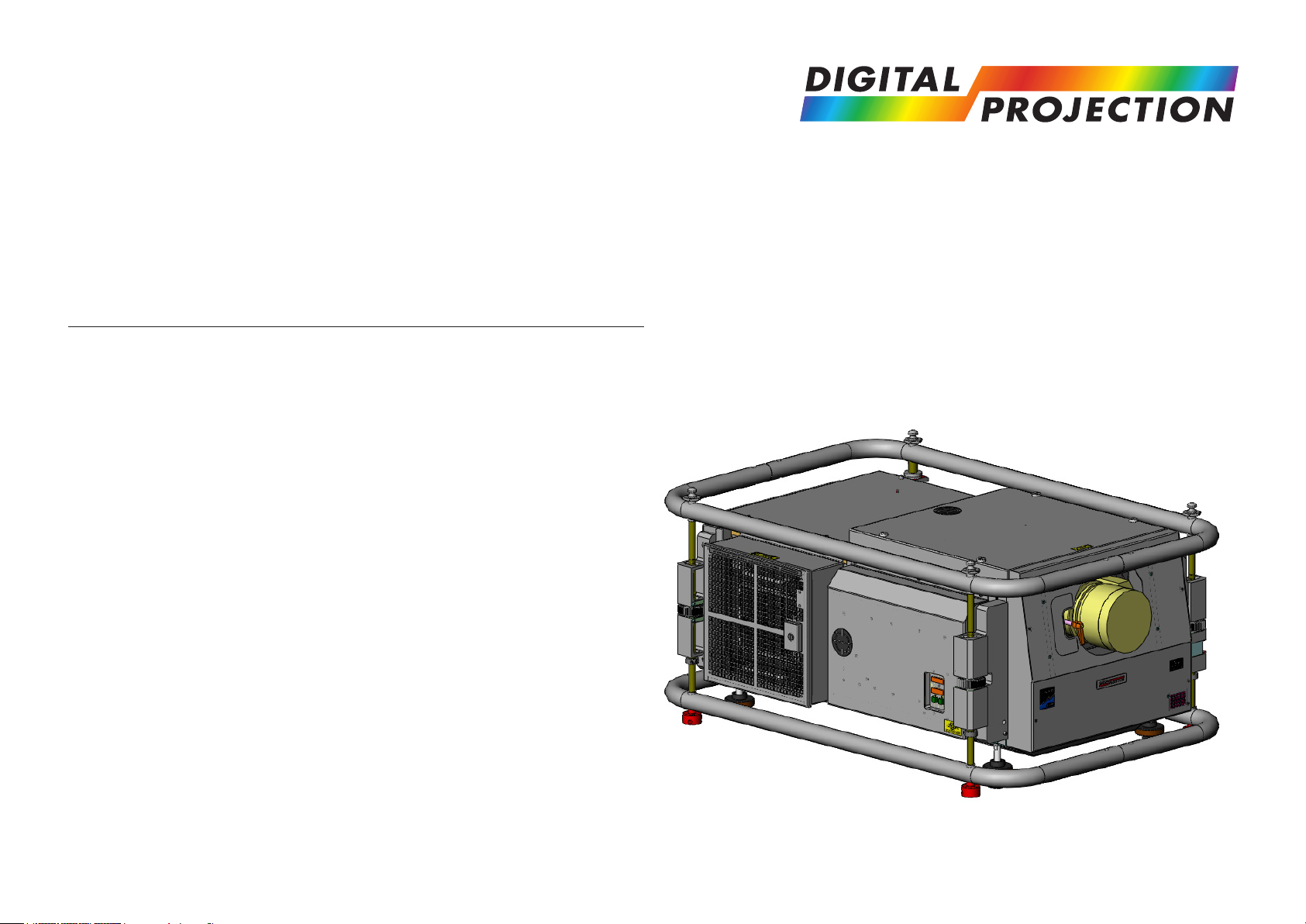
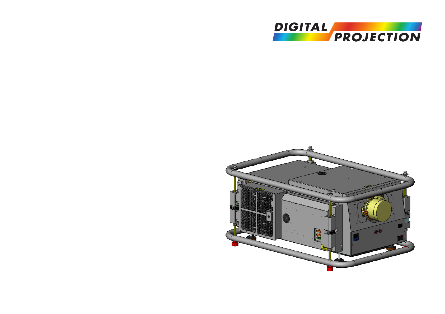
Lightning Series
High Brightness Digital Video Projector
USER MANUAL
INSTALLATION AND QUICK-START GUIDE
CONNECTION GUIDE
OPERATING GUIDE
REFERENCE GUIDE
Rev D July 2014
113-178D
Page 2

Digital Projection Lightning Series NoTOC
Digital Projection Lightning Series
About This Document
Please follow the instructions in this manual carefully to ensure safe and long-lasting use of the projector.
Keep this manual handy for future reference.
Symbols used in this manual
Many pages in this document have a dedicated area for notes. The information in that area is accompanied by the following symbols:
WARNING: this symbol indicates that there is a danger of physical injury to yourself and/or damage to the equipment unless
the instructions are closely followed.
ELECTRICAL WARNING: this symbol indicates that there is a danger of electrical shock unless the instructions are closely
followed.
NOTE: this symbol indicates that there is some important information that you should read.
Product revision
Because we at Digital Projection continually strive to improve our products, we may change specications and designs, and add new features
without prior notice.
Notes
Legal notice
Trademarks and trade names mentioned in this document remain the property of their respective owners.
Digital Projection disclaims any proprietary interest in trademarks and trade names other than its own.
Copyright © 2014 Digital Projection Ltd. All rights reserved.
iRev D July 2014
iRev D July 2014
Page 3

Digital Projection Lightning Series NoTOC
Digital Projection Lightning Series
Introduction
Congratulations on your purchase of this Digital Projection product.
Your projector has the following key features:
• Support for most 3D standards (if your projector is a 3D model)
• Full range of digital and legacy analog inputs
• Control of most aspects of the projector’s operation via LAN and RS232
• Support for a number of aspect ratios and screen sizes
• Non-linear warp adjustment by moving points on an interpolated grid
• Ceiling mount and rear-screen installation options
• Simultaneous display of two sources via Picture-In-Picture
• Long lamp life
• Motorised lens mount
A serial number is located on the back of the projector. Please record it here:
Notes
iiRev D July 2014
iiRev D July 2014
Page 4

Digital Projection Lightning Series NoTOC
Digital Projection Lightning Series
CONTENTS
INSTALLATION AND QUICK-START GUIDE ..............................1
WHAT’S IN THE BOX? ................................................................... 3
PROJECTOR OVERVIEW ............................................................... 4
Front and rear views ............................................................................. 4
Lamp compartment with hours meter.................................................... 5
LCD lamp-hours meter ............................................................................ 5
Control panel indicators ........................................................................ 6
Connection panel indicators .................................................................. 7
REMOTE CONTROL ....................................................................... 9
Infrared reception .................................................................................. 9
Remote control 105-023 Rev B ........................................................... 10
Remote control 105-023 Rev A ........................................................... 12
POSITIONING THE SCREEN AND PROJECTOR ........................... 13
Mounting the projector ........................................................................ 13
Adjustment for table mounting ................................................................. 13
Adjusting the rigging frame ..................................................................... 13
Coarse frame adjustment ....................................................................... 13
Pitch and roll adjustment ..................................................................... 14
Yaw adjustment ................................................................................... 14
Stacking projectors.............................................................................. 15
FITTING THE LENS ...................................................................... 16
OPERATING THE PROJECTOR .................................................... 17
Switching the projector on ................................................................... 17
Switching the projector off ................................................................... 18
Selecting an input signal or test pattern .............................................. 19
Input signal ........................................................................................ 19
Test pattern ........................................................................................ 19
Adjusting the lens ................................................................................ 20
Zoom ................................................................................................ 20
Focus ............................................................................................... 20
Shift ................................................................................................. 20
Adjusting the image............................................................................. 21
Orientation ......................................................................................... 21
Keystone ........................................................................................... 21
Picture .............................................................................................. 21
CONNECTION GUIDE ............................................................................23
SIGNAL INPUTS AND OUTPUTS .................................................. 25
Rear Connection Panel ....................................................................... 25
VGA (input 1) .................................................................................... 25
HDMI (input 2), DVI (input 3)................................................................ 25
SPDIF ............................................................................................... 25
3G-SDI (input 4) ................................................................................. 25
CVBS1 (input 5) ................................................................................. 25
S-Video (input 6) ................................................................................ 25
Component (input 7) ........................................................................... 25
CVBS2 (input 8) ................................................................................. 25
Side Connection Panel on 3D projectors ............................................ 26
DVI (input 9) ...................................................................................... 26
DVI/HDMI (input 10) ............................................................................ 26
Special considerations when using Inputs 9-11 .................................. 27
Differences between Inputs 9-11 and Inputs 1-8 ...........................................27
Input and processing architecture ............................................................ 27
iiiRev D July 2014
iiiRev D July 2014
Page 5

Digital Projection Lightning Series NoTOC
Digital Projection Lightning Series
CONTENTS (continued)
EDID on the DVI and VGA inputs........................................................28
Using HDMI/DVI switchers with the projector .............................................. 28
DVI Input connection example ............................................................ 29
3D connections ................................................................................... 30
3D sources up to 60Hz requiring frame doubling and left/right interleaving .......... 30
3D sources above 60Hz not requiring frame doubling .................................... 30
Dual Pipe 3D ...................................................................................... 30
3D Sync in ......................................................................................... 30
3D Sync out ....................................................................................... 30
3D connection examples ....................................................................... 31
CONTROL CONNECTIONS ........................................................... 32
Service port ......................................................................................... 32
Wired remote control ........................................................................... 32
RS232 ................................................................................................. 32
LAN ..................................................................................................... 32
Update port ......................................................................................... 32
LAN connection examples .................................................................. 33
RS232 connection example ................................................................ 34
OPERATING GUIDE ................................................................................35
USING THE PROJECTOR ............................................................. 41
Lens menu .......................................................................................... 42
Zoom ................................................................................................ 42
Focus ............................................................................................... 42
Calibrate Zoom and Calibrate Focus ......................................................... 42
Center Lens ....................................................................................... 42
Nudge ............................................................................................... 42
Lens Presets ...................................................................................... 43
Image menu ........................................................................................ 44
Video Filters ....................................................................................... 44
VGA Setup ......................................................................................... 44
Color menu.......................................................................................... 45
Gamut .............................................................................................. 45
Black Level and Gain sliders ................................................................... 45
Geometry menu .................................................................................. 46
Aspect Ratio ....................................................................................... 46
Overscan ........................................................................................... 46
Size & Position .................................................................................... 47
Blanking ............................................................................................ 47
Geometry Engine ................................................................................. 48
USING THE MENUS ..................................................................... 37
Menus and sub-menus........................................................................ 37
Drop-down lists ................................................................................... 38
Sliders ................................................................................................. 39
Commands .......................................................................................... 39
Editing elds ........................................................................................ 40
ivRev D July 2014
ivRev D July 2014
Page 6

Digital Projection Lightning Series NoTOC
Digital Projection Lightning Series
CONTENTS (continued)
Edge Blend menu................................................................................ 54
Overview ........................................................................................... 54
Array Width and Height ......................................................................... 55
Array H Position and V Position ............................................................... 55
S-Curve Value .................................................................................... 56
Blending ............................................................................................ 58
Segmentation ..................................................................................... 59
Blend Width........................................................................................ 61
Black Level Uplift ................................................................................. 61
Reduce Black Level Uplift Width .............................................................. 62
Blending images from multiple projectors ........................................... 65
Before you start ................................................................................... 65
Edge Blend procedure .......................................................................... 66
PIP menu ............................................................................................ 74
3D menu.............................................................................................. 75
3D types ............................................................................................ 76
Some 3D settings explained ............................................................... 78
Dark Time .......................................................................................... 78
Source Dominance ............................................................................... 78
Sync Offset ........................................................................................ 78
Frame Rate Multiplier............................................................................ 79
Lamp menu ......................................................................................... 80
Setup menu ......................................................................................... 81
Reset Default Settings .......................................................................... 81
Input Conguration ............................................................................... 82
Network ............................................................................................ 83
On Screen Display ............................................................................... 84
System ............................................................................................. 85
Setting up an IR address ....................................................................... 86
Information menu ................................................................................ 87
Conguration ...................................................................................... 87
REFERENCE GUIDE ................................................................................89
THE DMD™ .................................................................................. 92
CHOOSING A LENS ..................................................................... 94
Basic calculation ................................................................................. 95
Basic calculation example ................................................................... 96
Full lens calculation ............................................................................. 97
Introducing TRC .................................................................................. 97
Calculating TRC .................................................................................. 98
TRC table .......................................................................................... 98
Calculating the throw ratio with TRC ......................................................... 99
Full lens calculation example ............................................................ 100
vRev D July 2014
vRev D July 2014
Page 7

Digital Projection Lightning Series NoTOC
Digital Projection Lightning Series
CONTENTS (continued)
SCREEN REQUIREMENTS ......................................................... 101
Fitting the image to the DMD™ ......................................................... 101
SX+ images displayed full width ............................................................ 101
SX+ images displayed full height ........................................................... 101
1080p images displayed full width .......................................................... 102
1080p images displayed full height ......................................................... 102
WUXGA images displayed full width ....................................................... 103
WUXGA images displayed with a height of 1080 pixels ................................ 103
WUXGA images displayed full height ...................................................... 104
Diagonal screen sizes ....................................................................... 105
Fitting the image to the screen .......................................................... 106
Positioning the screen and projector ................................................. 107
POSITIONING THE IMAGE ......................................................... 108
Maximum offset range ....................................................................... 110
ASPECT RATIOS EXPLAINED ..................................................... 111
Aspect ratio examples for DMD™ resolution SX+ (SXGA+) ............. 11 2
Aspect ratio examples for DMD™ resolution 1080p ......................... 11 5
Aspect ratio examples for DMD™ resolution WUXGA...................... 118
Aspect ratio example: TheaterScope ................................................ 121
FRAME RATES AND PULLDOWNS EXPLAINED ......................... 122
Interlaced and progressive scan ....................................................... 122
Frame rates of image sources .......................................................... 122
Pulldowns - conversion into destination formats ............................... 123
2:3 (normal) pulldown ......................................................................... 123
2:3:3:2 (advanced) pulldown ................................................................. 124
APPENDIX B: LENS CHARTS .................................................... 126
How to use the lens charts ................................................................ 126
How to nd the right lens chart.......................................................... 127
1080p (1920 x 1080 pixels) .................................................................. 127
WUXGA (1920 x 1200 pixels)................................................................ 128
SX+ (1400 x 1050 pixels) ..................................................................... 129
DMD™ resolution 1080p / WUXGA, full width images...................... 130
DMD™ resolution 1080p, 1.25:1 images .......................................... 132
DMD™ resolution 1080p, 1.33:1 images .......................................... 134
DMD™ resolution 1080p, 1.6:1 images ............................................ 136
DMD™ resolution 1080p, 1.66:1 images .......................................... 138
DMD™ resolution WUXGA, 1.25:1 images....................................... 140
DMD™ resolution WUXGA, 1.33:1 images....................................... 142
DMD™ resolution SX+, full width images ......................................... 144
DMD™ resolution SX+, 1.25:1 images ............................................. 146
APPENDIX C: SUPPORTED SIGNAL INPUT MODES .................. 148
2D input modes ................................................................................. 148
3D input modes ................................................................................. 151
APPENDIX D: MENU MAP .......................................................... 153
APPENDIX A: LENS PART NUMBERS ........................................ 125
viRev D July 2014
viRev D July 2014
Page 8

Digital Projection Lightning Series NoTOC
Digital Projection Lightning Series
CONTENTS (continued)
APPENDIX E: WIRING DETAILS ................................................. 160
Signal inputs and outputs .................................................................. 160
Input 1: VGA ..................................................................................... 160
Input 2: HDMI ................................................................................... 161
Output: SPDIF .................................................................................. 161
Input 3: DVI ...................................................................................... 162
Input 4: 3G-SDI ................................................................................. 163
Input 5: Composite 1 .......................................................................... 163
Input 6: S-Video ................................................................................ 163
Input 7: Component ............................................................................ 163
Input 8: CVBS ................................................................................... 163
Input 9: MAIN/DVI .............................................................................. 164
Input 10: SUB/HDMI ........................................................................... 165
Control connections .......................................................................... 166
Update port ...................................................................................... 166
Wired remote control .......................................................................... 166
RS232 ............................................................................................ 167
LAN connection ................................................................................. 167
APPENDIX F: GLOSSARY OF TERMS ........................................ 168
TECHNICAL SPECIFICATIONS .................................................. 178
Models............................................................................................... 178
Inputs and outputs............................................................................. 179
Bandwidth ......................................................................................... 179
Remote control and keypad .............................................................. 179
Automation control ............................................................................ 179
Color temperature ............................................................................. 179
Lamps ............................................................................................... 180
Lenses............................................................................................... 181
Lens mount ....................................................................................... 181
Mechanical mounting ........................................................................ 181
Orientation......................................................................................... 181
Electrical and physical specications ................................................ 182
Safety & EMC regulations ................................................................. 182
Accessories ....................................................................................... 182
viiRev D July 2014
viiRev D July 2014
Page 9
INSTALLATION AND QUICK-START GUIDE
Lightning Series
High Brightness Digital Video Projector
Rev D July 2014
Page 10

Digital Projection Lightning Series IN THIS GUIDE Installation and Quick-Start Guide
IN THIS GUIDE
What’s In The Box? ............................................................................................. 3
Projector Overview ............................................................................................. 4
Front and rear views ...................................................................................................4
Lamp compartment with hours meter .......................................................................5
LCD lamp-hours meter ...................................................................................................... 5
Control panel indicators .............................................................................................6
Connection panel indicators ......................................................................................7
Remote Control .................................................................................................... 9
Infrared reception ........................................................................................................9
Remote control 105-023 Rev B ................................................................................10
Remote control 105-023 Rev A ................................................................................. 12
Positioning The Screen And Projector ....................................................... 13
Mounting the projector .............................................................................................13
Adjustment for table mounting ........................................................................................13
Adjusting the rigging frame .............................................................................................13
Coarse frame adjustment ................................................................................................13
Pitch and roll adjustment .........................................................................................14
Yaw adjustment .........................................................................................................14
Stacking projectors ...................................................................................................15
Adjusting the lens .....................................................................................................20
Zoom ...............................................................................................................................20
Focus ..............................................................................................................................20
Shift .................................................................................................................................20
Adjusting the image ..................................................................................................21
Orientation ......................................................................................................................21
Keystone .........................................................................................................................21
Picture .............................................................................................................................21
Fitting The Lens ................................................................................................ 16
Operating The Projector ................................................................................. 17
Switching the projector on .......................................................................................17
Switching the projector off .......................................................................................18
Selecting an input signal or test pattern .................................................................19
Input signal ......................................................................................................................19
Test pattern .....................................................................................................................19
Rev D July 2014
Page 11
Digital Projection Lightning Series WHAT’S IN THE BOX? Installation and Quick-Start Guide
VGA HDMI DVI 3GSDI
CVBS1 SVIDEO
CLOSE
1
2 3 4
COMP CVBS2
5 6 7 8
9 0 10+ #
MAIN SUB
DUAL
HD-T
OFF
ON
ALT
ROLL
PITCH
YAW
FOCUS
CAL
SHIFT
ZOOM
EYE
SWAP
MAIN/PIP
SWAP
BRI
CON GAMMA
3D
ON/OFF
PIP
ON/OFF
LOAD
SAVE
TEST ADDR
BACKLIGHT
R
G
B
PRESET
SHUTTER
OPEN
POWER
MENU
OK
EXIT
INFO
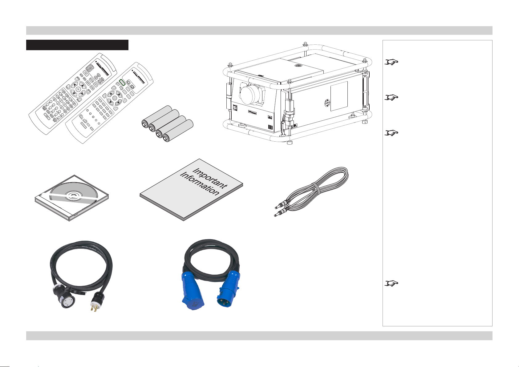
What’s In The Box?
Remote control
(105-023) Rev A or B
4x AAA batteries
Notes
Make sure your box contains
everything listed. If any pieces are
missing, contact your dealer.
You should save the original box
and packing materials, in case you
ever need to ship your projector.
The projector is shipped without a
lens.
Projector
User Manual on disc
(115-759)
Important Information (113-182)
Remote cable
(102-162)
Only one power cable - dependent
on the destination territory - will be
Power cable, USA
(LA00098)
Power cable, Rest of World
(LA00097)
supplied with the projector.
3Rev D July 2014
Page 12
Digital Projection Lightning Series PROJECTOR OVERVIEW Installation and Quick-Start Guide
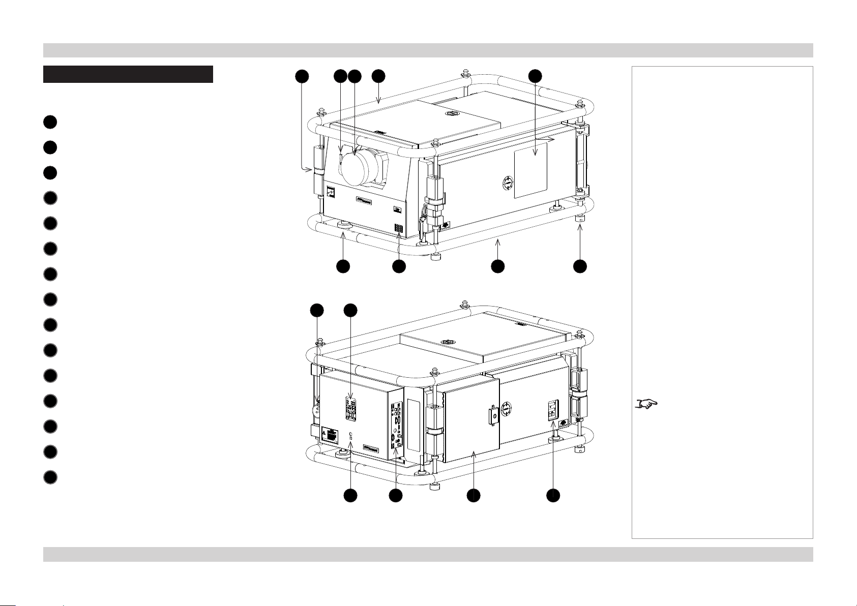
Projector Overview
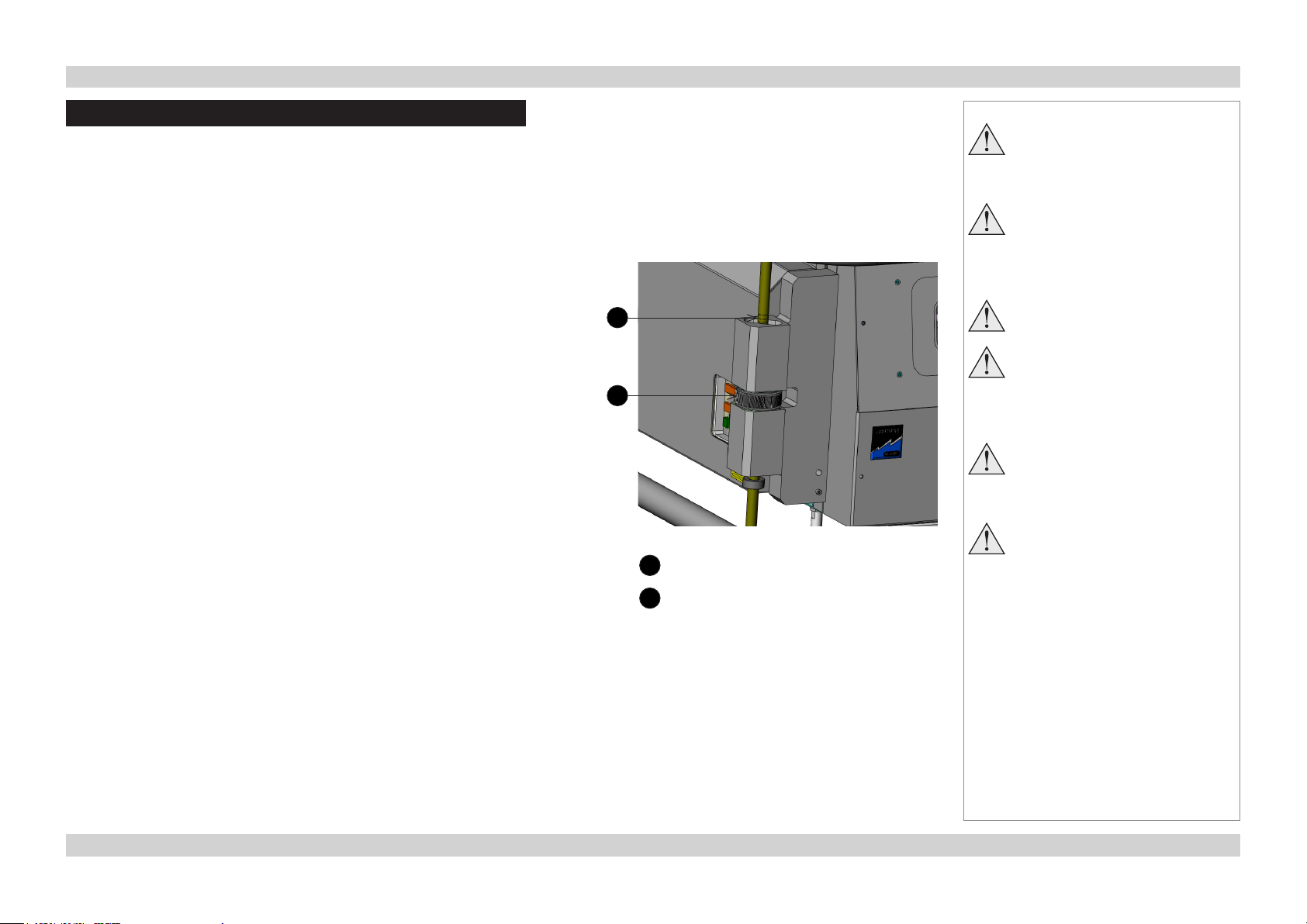
Front and rear views
Frame adjuster
1
Lens release lever
2
Lens
3
Rigging frame
4
Air outlets
5
Adjustable foot
6
Front infrared window
7
Air inlet
8
Stacking adapter
9
Power switch and power connection
10
10
2 4
11
1 3
7 96
Front view
5
8
Notes
Control panel
11
Rear infrared window
12
Rear connection panel
13
Lamp compartment with air outlet
14
Side connection panel
15
12 13
The side connection panel is
available on 3D models only.
1514
Rear view
4Rev D July 2014
Page 13
Digital Projection Lightning Series PROJECTOR OVERVIEW Installation and Quick-Start Guide
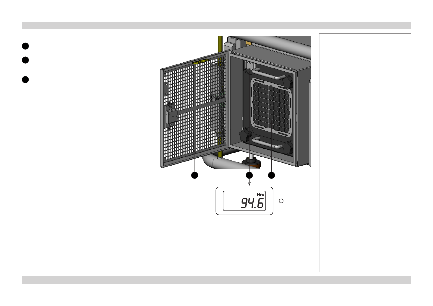
Lamp compartment with hours meter
Compartment door
1
2
3
LCD lamp-hours meter
The LCD lamp-hours meter has two modes of operation:
Open to access the lamp compartment.
Lamp-hours meter with LCD display
Shows how long the lamp has been in
operation.
Air outlet
Blows hot air out to prevent lamp
overheating.
• When the lamp is switched on, the LCD will show lamp run
hours.
• When the lamp is switched off, the LCD will be blank.
Press the button and hold for 5 seconds to display lamp
run hours.
Notes
2 31
5Rev D July 2014
Page 14
Digital Projection Lightning Series PROJECTOR OVERVIEW Installation and Quick-Start Guide
Control panel indicators
Power indicator
1
Behavior Meaning
Off The projector is switched off.
On (amber) The projector is in Standby mode.
On (green) The projector is switched on (Normal mode).
Shutter indicator
2
Behavior Meaning
On (amber) The shutter is closed.
On (green) The shutter is open.
Notes
During startup all LEDs light up
at the same time to indicate the
projector is carrying out a self-test.
1
2
6Rev D July 2014
Page 15
Digital Projection Lightning Series PROJECTOR OVERVIEW Installation and Quick-Start Guide
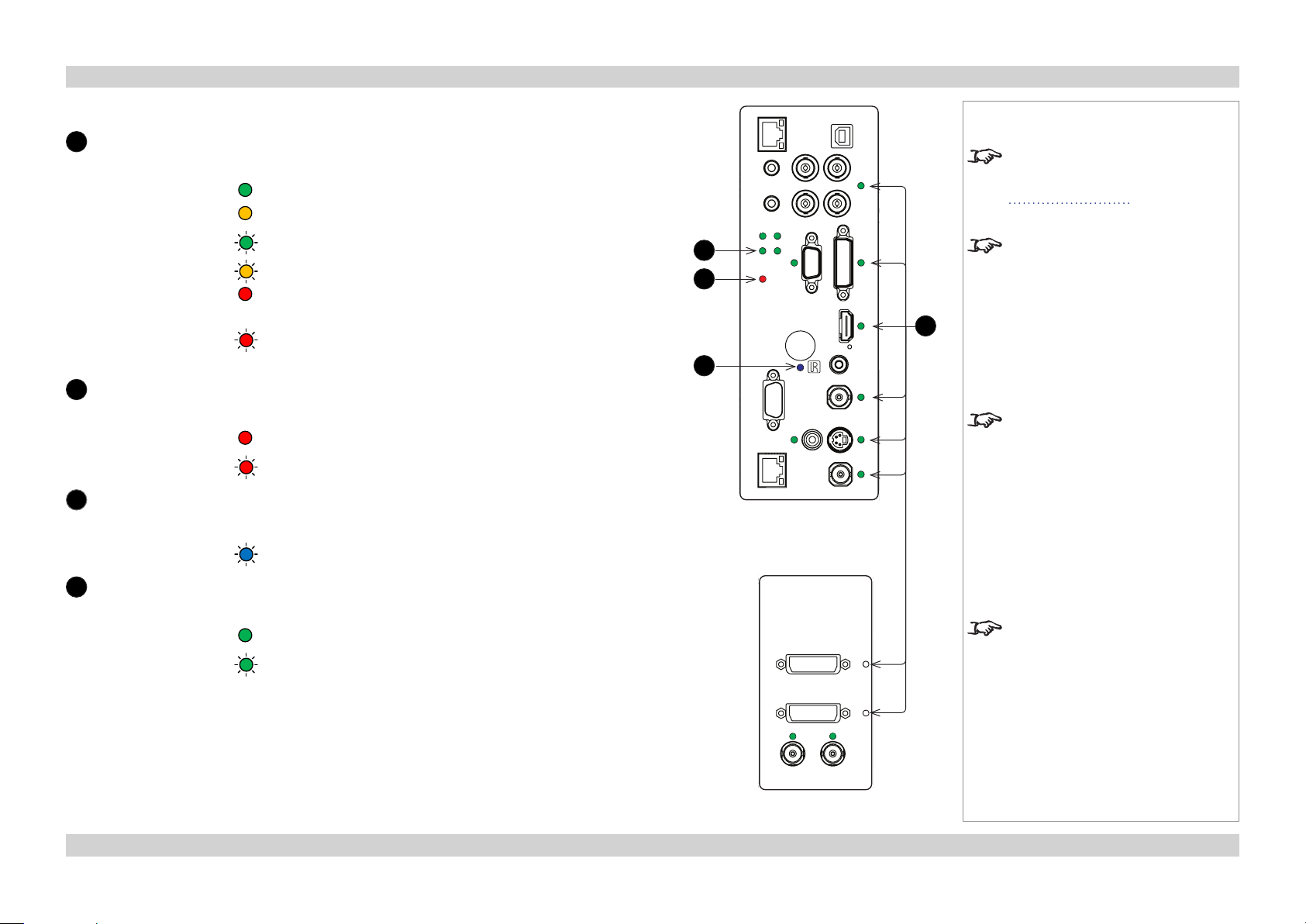
Connection panel indicators
1
Lamp 1 indicator
Behavior Meaning
On (green) The lamp is switched on (100%).
On (amber) The lamp is switched on (80-99%).
Flashing (green) The lamp is warming up.
Flashing (amber) The lamp is cooling down.
On (red) Projector in standby: Lamp Comms Error (call service)
Projector on: Ballast Comms Error (call service)
Flashing (red) Projector in standby: Lamp Error on previous operation
Projector on: Lamp / Interlock Error
2
Error indicator
Behavior Meaning
On (red) Voltage Error
Flashing (red) Fan / System Error
3
Infrared indicator
Behavior Meaning
Flashing (blue) The projector is receiving input from the remote control.
1
2
3
Rear connection panel
Notes
For more information about
the connection panels, see the
Connection Guide.
Only the Lamp 1 indicator is active
on this projector.
4
A red LED always indicates an error.
If you receive an error indication,
restart the projector. If the problem
persists, contact your dealer.
4
Input indicators
Behavior Meaning
On (green)
Input selected. Signal detected and in range.
Flashing (green) Input selected, but signal is not detected or out of range.
The side connection panel is
available on 3D models only.
Side connection panel
7Rev D July 2014
Page 16
Digital Projection Lightning Series PROJECTOR OVERVIEW Installation and Quick-Start Guide
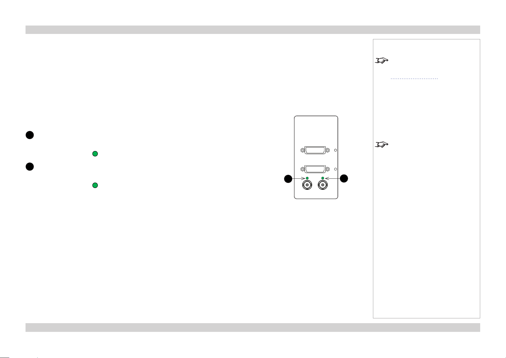
Connection panel indicators - continued from previous page
5
Sync in indicator
Behavior Meaning
On (green)
6
Sync out indicator
Valid sync in.
Behavior Meaning
On (green)
Valid sync out.
5
Side connection panel
Notes
For more information about
the connection panels, see the
Connection Guide.
The side connection panel is
available on 3D models only.
6
8Rev D July 2014
Page 17
Digital Projection Lightning Series REMOTE CONTROL Installation and Quick-Start Guide
Remote Control
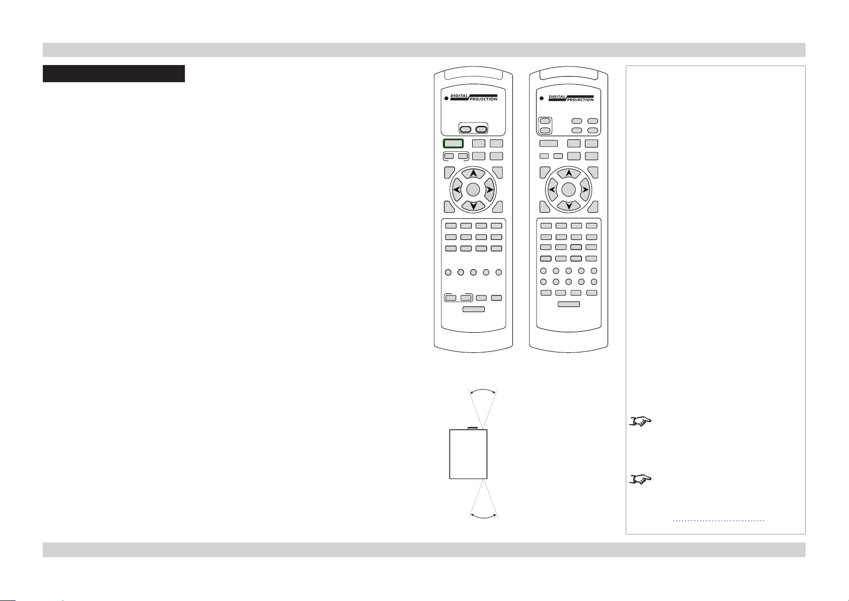
The projector is equipped with one of the remote control devices shown here. The device on
the left (105-023 Rev B) was introduced in June 2013; a projector purchased before that date
is equipped with the device on the right, 105-023 Rev A.
Both devices and their functions are described in the following pages.
POWER
OFF
ON
FOCUS
ROLL
SHIFT
PITCH
OK
2 3 4
COMP CVBS2
DUAL
EYE
B
SWAP
3D
ON/OFF
TEST ADDR
BACKLIGHT
ZOOM
MAIN/PIP
CAL
YAW
INFO
HD-T
SWAP
ON/OFF
PIP
ALT
CLOSE
OPEN
SHUTTER
MENU
EXIT
1
VGA HDMI DVI 3GSDI
5 6 7 8
CVBS1 SVIDEO
9 0 10+ #
MAIN SUB
G
R
BRI
CON GAMMA
PRESET
LOAD
SAVE
Remote (105-023)
Rev B
ON
POWER
OFF
AUTO
MENU INPUT
EXIT
1 RGB1 3 DVI RED
4 SDI 5 VID 6 SVID GREEN
7 COM 8 9 BLUE
10+ 0 # TEST
BRI
OSD POS
PRESET
PRESET
OFF
OSD
ON
CTRL FOCUS
INFO
SHIFT
OK
2 RGB2
A B C D
E F G H
J K L M
N P R S
CON SAT MAGNIFY PHASE
KEYST
PAN ASPECT
FUNC ADDR SAVE
LIGHT
OPEN
SHUTTER
CLOSE
RPY
ZOOM
INPUT
SAVE
+
_
Remote (105-023)
Rev A
Notes
Infrared reception
The projector has infrared sensors at the front and back.
The angle of acceptance is 40°. Make sure that the remote control is within the angle of
acceptance when trying to control the projector.
40°
40°
Infrared reception
Infrared reception is conrmed by
the blue IR LED ashing on the
control panel.
The infrared receivers are disabled
when a remote control is connected
via a cable. For more information,
see Wired remote control in the
Connection Guide.
9Rev D July 2014
Page 18
Digital Projection Lightning Series REMOTE CONTROL Installation and Quick-Start Guide
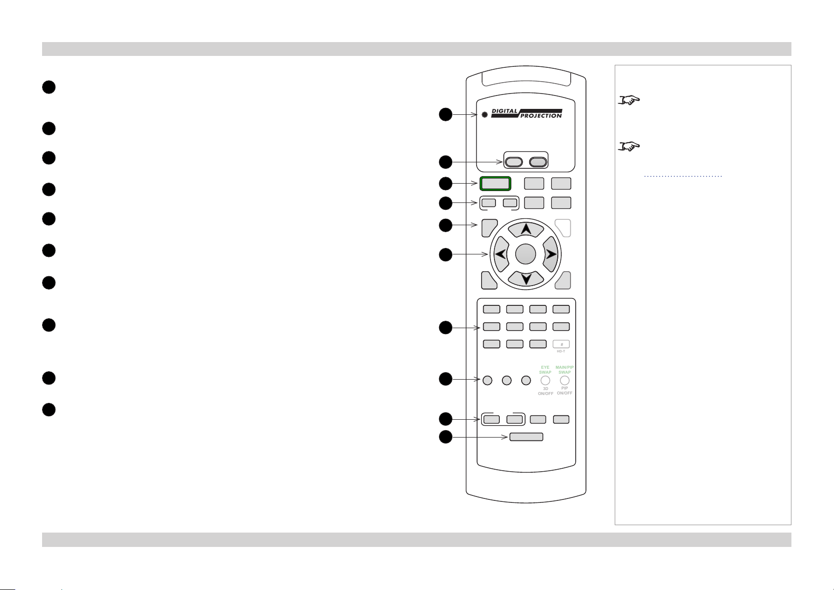
Remote control 105-023 Rev B
Transmit indicator
1
Flashes when the remote control sends a signal to the projector.
Lights solidly when the projector is in LENS ADJUSTMENT mode.
2
Power ON / OFF
3
ALT
Press and hold this button, then press a green-labeled button.
4
Shutter OPEN / CLOSE
5
MENU
Access the projector OSD (on-screen display).
6
Navigation
Navigate through the menus with the arrows, conrm your choice with OK.
7
Input selection
Select input source.
9, 0, 10+ and # are not used on 2D projectors.
8
Image adjustment
Adjust brightness, contrast and gamma.
Press this button while holding the ALT button down to switch red, green and blue
channels on and off.
9
Presets
Save and recall lens presets.
Notes
Only the controls shown highlighted
1
POWER
OFF
2
3
4
5
ALT
CLOSE
SHUTTER
MENU
6
EXIT
1
VGA HDMI DVI 3GSDI
7
8
5 6 7 8
CVBS1 SVIDEO
9 0 10+ #
MAIN SUB
R
BRI
CON GAMMA
ON
FOCUS
ROLL
SHIFT
OPEN
PITCH
OK
2 3 4
COMP CVBS2
DUAL
B
G
EYE
SWAP
3D
ON/OFF
CAL
ZOOM
YAW
INFO
HD-T
MAIN/PIP
SWAP
PIP
ON/OFF
are used on this projector.
For more information about
LENS ADJUSTMENT mode, see
Adjusting the lens further in this
guide.
10
Remote control backlight ON / OFF
Make the remote control buttons glow in the dark, or switch this feature off.
continues on next page...
PRESET
10
9
LOAD
SAVE
TEST ADDR
BACKLIGHT
Remote control 105-023 Rev B
10Rev D July 2014
Page 19
Digital Projection Lightning Series REMOTE CONTROL Installation and Quick-Start Guide
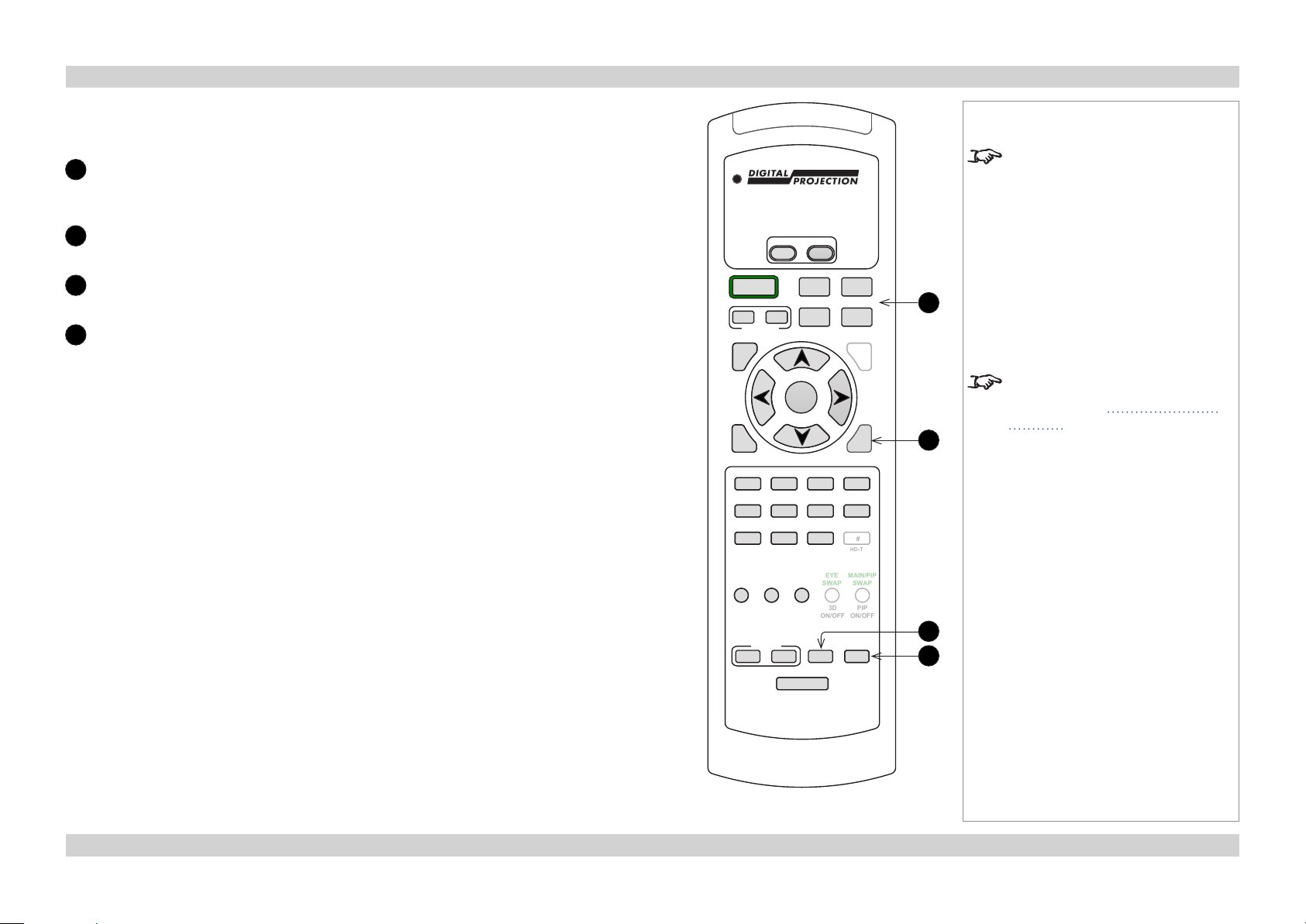
Remote control 105-023 Rev B - continued from previous page
11
Lens controls
Adjust position, zoom and focus.
Perform calibration when you change the lens.
12
INFO
Open the Information menu.
13
TEST
Switch to test pattern.
14
IR address
Set up an address to match the IR address of a projector.
POWER
OFF
ON
ALT
CLOSE
SHUTTER
MENU
EXIT
1
VGA HDMI DVI 3GSDI
5 6 7 8
CVBS1 SVIDEO
9 0 10+ #
MAIN SUB
R
BRI
PRESET
LOAD
FOCUS
SHIFT
OPEN
PITCH
OK
2 3 4
B
G
CON GAMMA
SAVE
BACKLIGHT
ROLL
COMP CVBS2
DUAL
EYE
SWAP
3D
ON/OFF
TEST ADDR
CAL
ZOOM
YAW
INFO
HD-T
MAIN/PIP
SWAP
PIP
ON/OFF
Notes
Only the controls shown highlighted
are used on this projector.
11
For more information about IR
addresses, see Setting up an IR
address in the Operating Guide.
12
13
14
Remote control 105-023 Rev B
11Rev D July 2014
Page 20
Digital Projection Lightning Series REMOTE CONTROL Installation and Quick-Start Guide
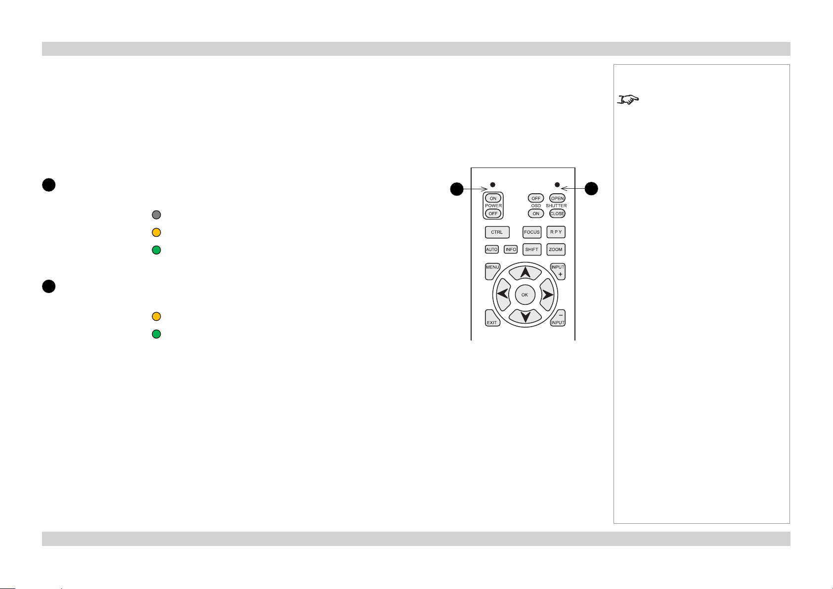
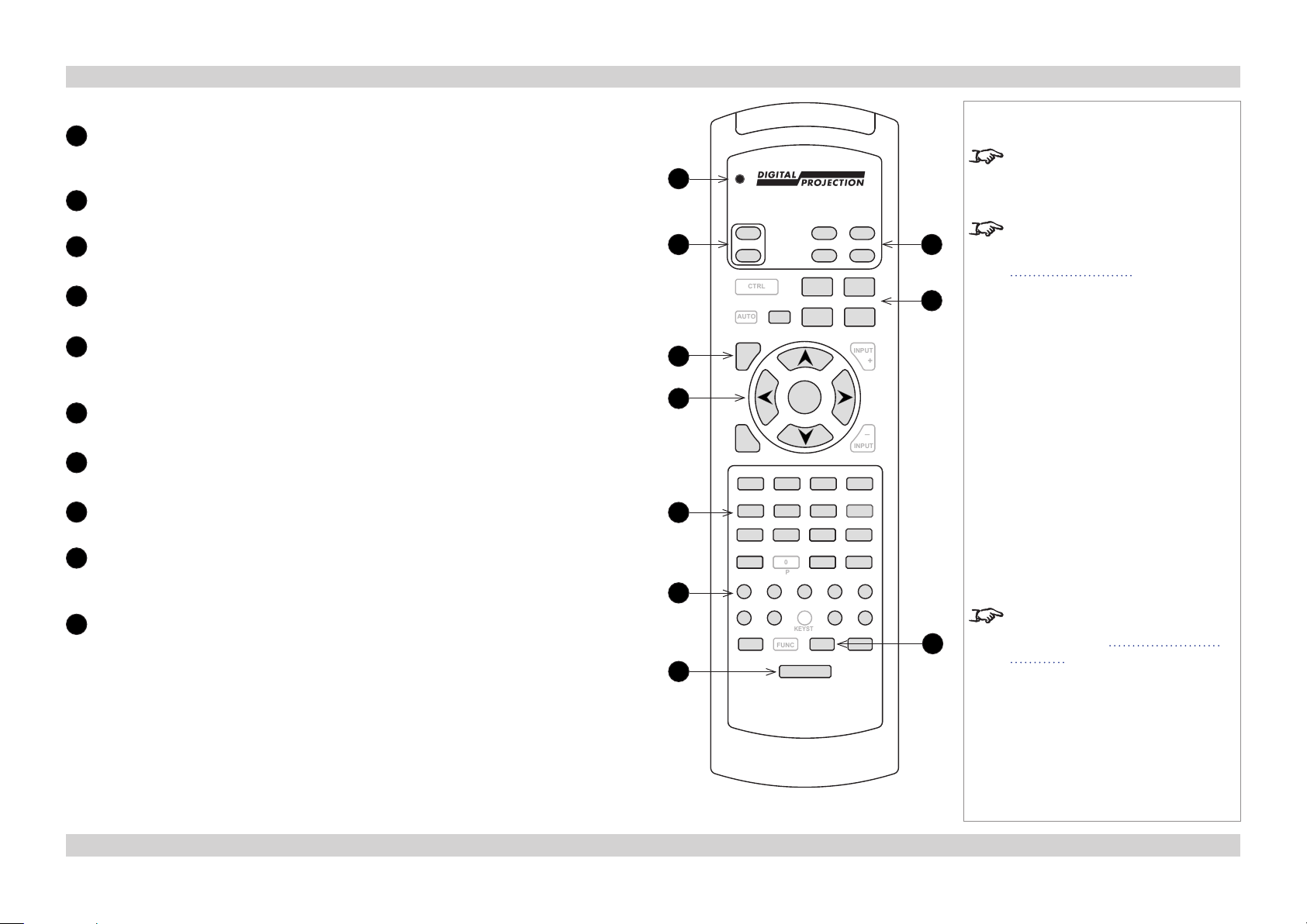
Remote control 105-023 Rev A
Transmit indicator
1
Flashes when the remote control sends a signal to the projector.
Lights solidly when the projector is in LENS ADJUSTMENT mode.
2
Power ON / OFF
3
MENU
Access the projector OSD (on-screen display).
4
Navigation
Navigate through the menus with the arrows, conrm your choice with OK.
5
Input selection
Select input source.
9, 10+ and # are not used on 2D projectors.
6
Image adjustment
Adjust brightness, contrast and saturation.
7
Remote control backlight ON / OFF
Make the remote control buttons glow in the dark, or switch this feature off.
8
Shutter OPEN / CLOSE
9
Lens controls
Adjust position, zoom and focus. Perform RPY calibration when you change the
lens.
10
IR address
Set up an address to match the IR address of a projector.
Notes
Only the controls shown highlighted
1
ON
2
POWER
OFF
CTRL FOCUS
OFF
OSD
OPEN
SHUTTER
ON
CLOSE
RPY
8
9
SHIFT
ZOOM
+
_
INPUT
PAN ASPECT
SAVE
10
INFO
AUTO
3
4
5
6
7
MENU INPUT
OK
EXIT
2 RGB2
1 RGB1 3 DVI RED
A B C D
4 SDI 5 VID 6 SVID GREEN
E F G H
7 COM 8 9 BLUE
J K L M
10+ 0 # TEST
N P R S
BRI
CON SAT MAGNIFY PHASE
OSD POS
PRESET
PRESET
KEYST
FUNC ADDR SAVE
LIGHT
are used on this projector.
For more information about
LENS ADJUSTMENT mode, see
Adjusting the lens further in this
guide.
For more information about IR
addresses, see Setting up an IR
address in the Operating Guide.
Remote control 105-023 Rev A
12Rev D July 2014
Page 21
Digital Projection Lightning Series POSITIONING THE SCREEN AND PROJECTOR Installation and Quick-Start Guide
Positioning The Screen And Projector
1. Install the screen, ensuring that it is in the best position for viewing by your
audience.
2. Position the projector, ensuring that it is at a suitable distance from the screen
for the image to ll the screen.
Mounting the projector
The projector is designed to be suspended from a lighting truss by its rigging
frame. However, the four adjustable feet under the chassis allow the projector to be
lowered onto a at surface without any danger of hands being trapped between the
bottom frame and the surface.
Adjustment for table mounting
If the projector is to be operated from a at surface such as a projector table, then
adjustment of projector level should be made by turning the four feet under the
chassis.
Adjusting the rigging frame
Before suspending the projector, make sure that the three frame adjusters and the
yaw adjustment are set roughly midway. Centering lines are scribed on the shafts to
show the centres of adjustment.
Coarse frame adjustment
Coarse adjustment of projector level should be made by adjusting the length of the
supporting wires or chains, or by adjusting the position of the truss.
Once the initial coarse frame adjustment has been made, ne adjustment should be
made using the three frame adjusters and the yaw handle (if ttled) on the rigging
frame.
Notes
Always allow the projector to
cool for ve minutes before
disconnecting the power or
moving the projector.
Ensure that there is at least 30
cm (12 in.) of space between the
ventilation outlets and any wall,
and 10 cm (4 in.) on all other
sides.
1
2
1
Centering line
2
Frame adjuster
Do not stack more than three
projectors.
Do not place heavy objects on top
of the projector chassis. Only the
chassis corners and the rigging
frame are capable of withstanding
the weight of another projector.
Do not place the projector with its
front panel down on a surface, as
this may damage the lens or the
lens release lever.
Backup safety chains or wires
should always be used with
ceiling mount installations.
13Rev D July 2014
Page 22
Digital Projection Lightning Series POSITIONING THE SCREEN AND PROJECTOR Installation and Quick-Start Guide
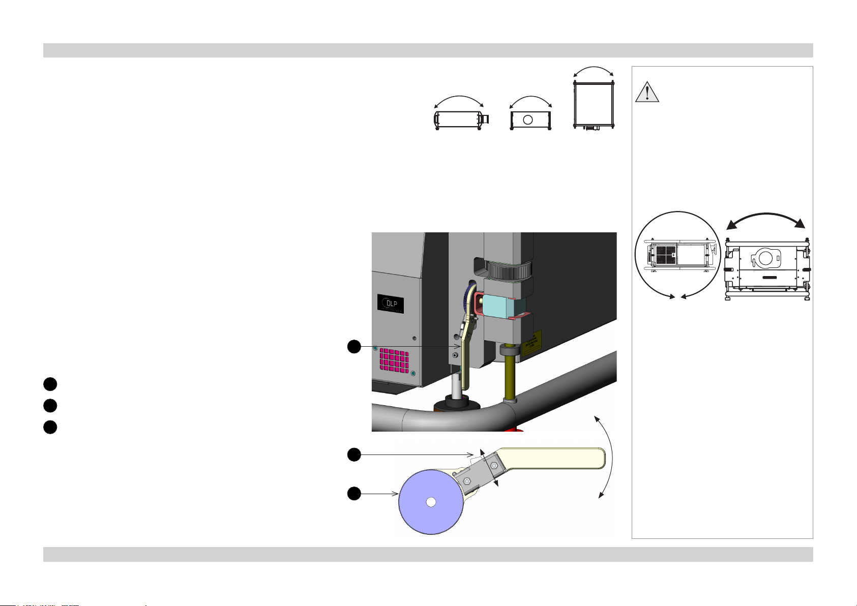
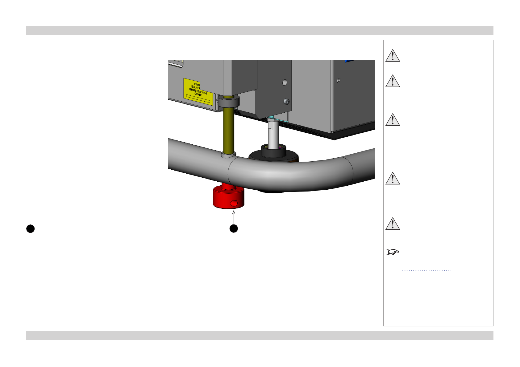
Pitch and roll adjustment
The frame adjusters can provide approximately ±10 mm of vertical movement
relative to the rear right corner, giving approximately ±0.65° pitch and ±0.85°
roll.
It is not possible to achieve maximum adjustment in pitch, roll and yaw
simultaneously.
Yaw adjustment
The yaw handle uses a ratchet to move the front of the projector from
left to right. To change the direction of movement, push the direction
lever on the handle up or down.
The yaw handle can provide approximately ±11 mm of left-right
movement relative to the rear right corner, giving approximately ±0.75°
yaw.
It is not possible to achieve maximum adjustment in tilt, roll and yaw
simultaneously.
Notes
Do not tilt the projector more than
±12° from side to side when in
use, as this may cause serious
lamp failure, damage the lamp
module and cause extra cost on
Pitch Roll Yaw
1
replacement.
The projector my be tilted
forwards and backwards as
necessary.
360°
±12°
1
Yaw handle
2
Direction lever
2
Ratchet
2
3
14Rev D July 2014
Page 23
Digital Projection Lightning Series POSITIONING THE SCREEN AND PROJECTOR Installation and Quick-Start Guide
Stacking projectors
The rigging frame is capable of supporting the weight
of up to three other projectors, using the built-in
stacking adapters. The projectors can be stacked on
top of each other, or suspended below each other.
1. Carefully lower each projector down onto the top
of the others, making sure that all four stacking
adapters engage fully.
2. Fit a locking pin into each adapter. A ball in the
end of the pin prevents the pin from falling out –
to insert or remove a locking pin, press the button
on the t-bar to release the ball.
Notes
Do not try to stack more than four
projectors.
When stacking projectors, the
stack MUST be vertical, to ensure
that the stresses are distributed
to all four stacking adapters.
Make sure that the surface,
ceiling or rigging that is to
support the projector is capable
of supporting the combined
weight of all the projectors and
lenses (see specication for
weights).
Do not place heavy objects on
top of the projector chassis.
Only the rigging frame is capable
of withstanding the weight of
another projector.
1
Stacking adapter with hole for locking pin
1
Separate backup safety chains or
wires should always be used for
each projector.
For information about aligning the
images from the projectors, see
Edge Blend menu in the Operating
Guide.
15Rev D July 2014
Page 24
Digital Projection Lightning Series FITTING THE LENS Installation and Quick-Start Guide
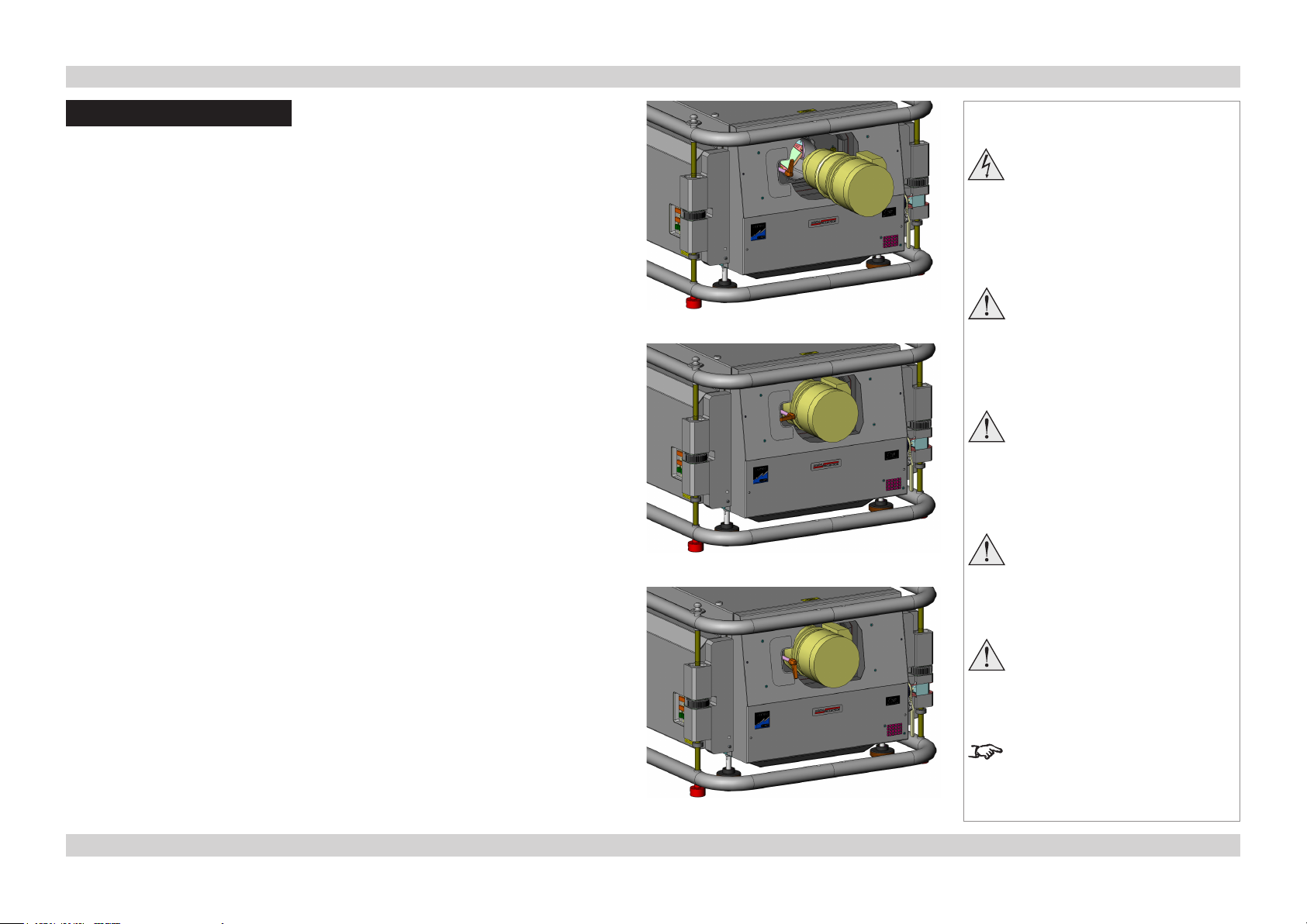
Fitting The Lens
1. Turn the lens release lever clockwise so that it is pointing upwards, to open the lock
fully.
2. Remove the rear lens cap from the lens.
3. Insert the lens into the lens aperture, making sure that the plug on the zoom drive
mechanism lines up with the socket on the front of the projector, then push the lens in
rmly as far as it will go.
4. Turn the lens release lever anti-clockwise to the mid-position.
5. The lens can now be pushed in further. Push the lens in rmly as far as it will go
6. Turn the lens release lever fully anti-clockwise so that it is pointing downwards, to
close the lock fully.
Lens release lever pointing upwards
Lens release lever in mid-position
Notes
Before changing the lens,
always make sure the projector
is switched off and fully
disconnected from its power
supply.
Always allow the projector to
cool for ve minutes before
disconnecting the power or
moving the projector.
The lens release lever should
always be set to the locked
position to prevent the lens from
falling out.
Do not place the projector with its
front panel down on a surface, as
this may damage the lens or the
lens release lever.
Lens release lever pointing downwards
Avoid touching the surface of the
lens as this may result in image
impairment.
Take care to preserve the original
lens packaging and protective caps
for future use.
16Rev D July 2014
Page 25
Digital Projection Lightning Series OPERATING THE PROJECTOR Installation and Quick-Start Guide
Operating The Projector
Switching the projector on
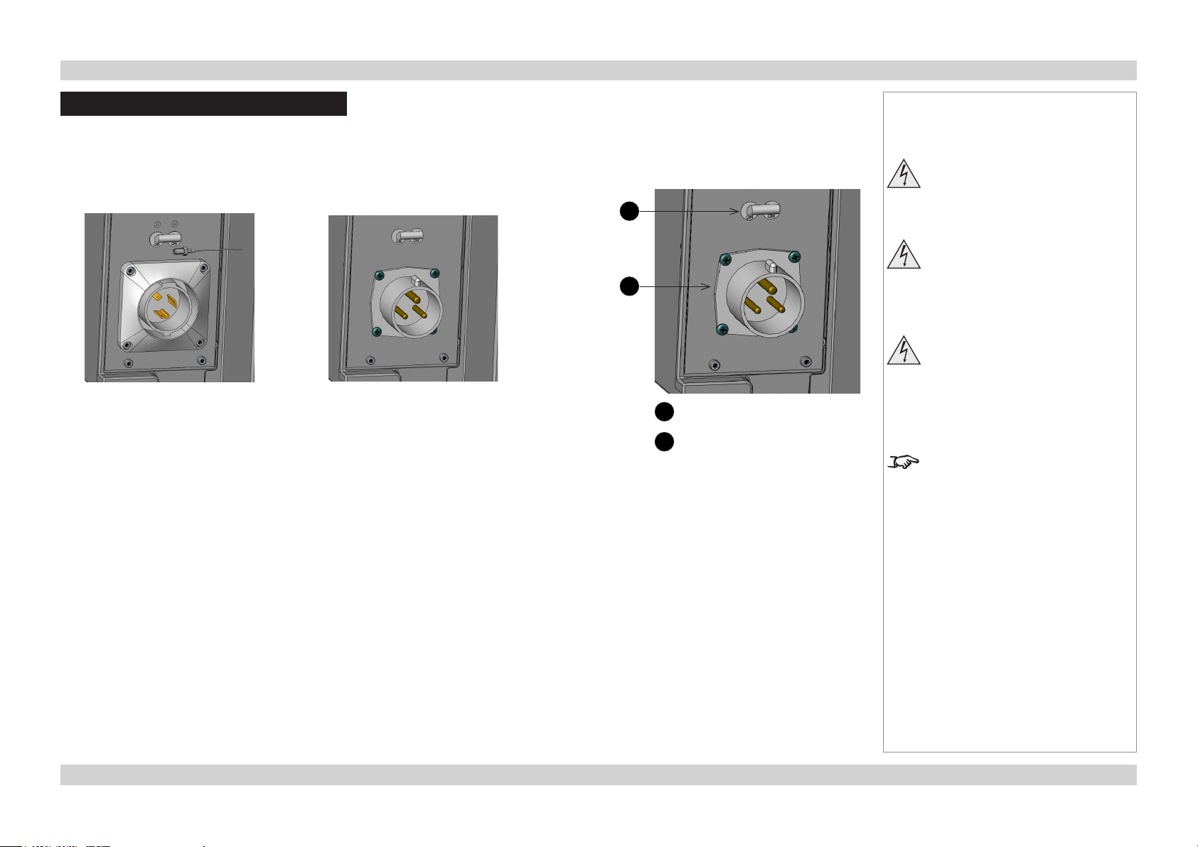
1. Make sure the mains power switch is off, then connect the power cable between the mains
supply and the projector, depending on your location:
USA power input
Firmly push in the Hubbell connector,
then turn clockwise to lock.
2. Push the mains power switch upwards to switch the power ON.
3. Wait until the self-test has completed and the standby indicator on the projector control
panel shows amber. The lamp will be off and the projector will be in STANDBY mode.
4. Press ON on the remote control or the control panel and hold for 3 seconds, to switch the
projector ON. The power indicator on the control panel will show green, the lamp will light
and the shutter will open.
Rest of the world power input
Lift the lid of the C-form connector,
then rmly push in the connector.
Notes
Use only the power cable
1
2
1
Mains power switch
2
Power connection
provided.
Ensure that the power outlet
includes a ground connection as
this equipment MUST be earthed.
Handle the power cable carefully
and avoid sharp bends. Do not
use a damaged power cable.
The self-test is running when all the
LEDs on the control panel are lit.
17Rev D July 2014
Page 26
Digital Projection Lightning Series OPERATING THE PROJECTOR Installation and Quick-Start Guide
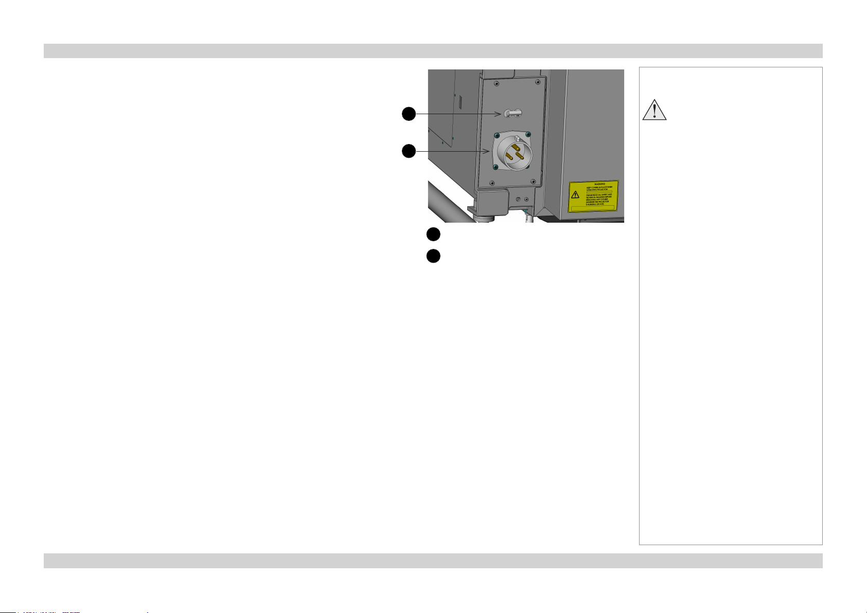
Switching the projector off
1. Press OFF on the remote control or the control panel, and hold for three
seconds. The power indicator on the control panel will show amber, the lamp
will switch off and the projector will go into STANDBY mode.
2. If you need to switch the projector off completely, switch off at the mains power
switch and then disconnect the power cable from the projector.
Notes
1
2
1
Mains power switch
2
Power connection
Always allow the lamp to cool for
ve minutes before:
- disconnecting the power
- moving the projector
18Rev D July 2014
Page 27
Digital Projection Lightning Series OPERATING THE PROJECTOR Installation and Quick-Start Guide
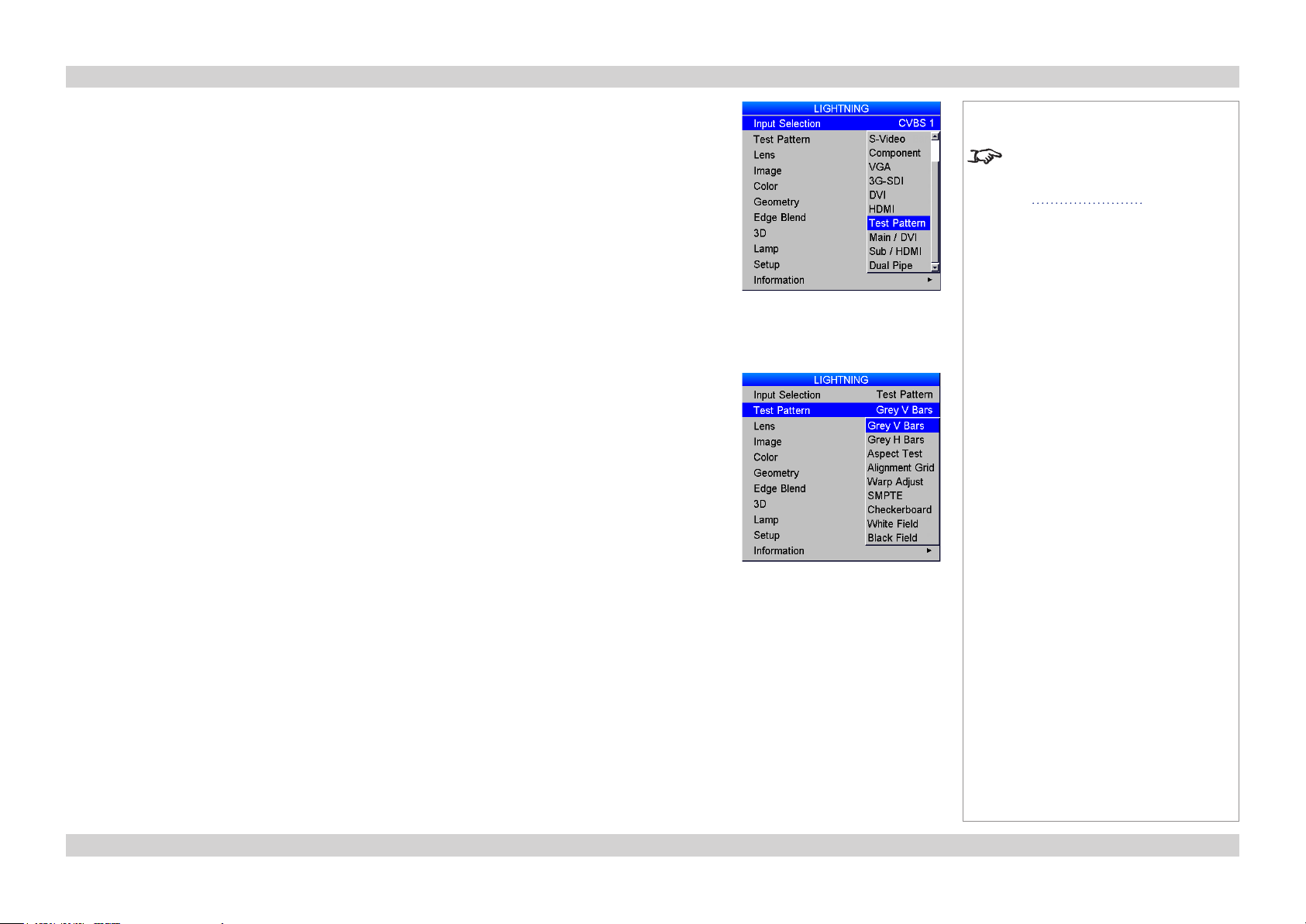
Selecting an input signal or test pattern
Input signal
1. Connect an image source to the projector.
2. Switch to the input you want to display:
• Press one of the input buttons on the remote control, or
• Open the On-screen display (OSD) by pressing MENU. Select an input signal from the Input
Selection menu, using the UP and DOWN arrow buttons, then press OK.
Test patter n
If no image source is connected to the projector, you can display a test pattern:
1. Open the OSD by pressing MENU.
2. Select Test Patter n from the Input Selection menu, using the UP and DOWN arrow buttons, then
press OK.
3. Select a pattern from the Test Patter n menu, using the UP and DOWN arrow buttons, then press
OK.
4. Close the OSD by pressing MENU again.
Notes
For full details of how to use the
controls and the menu system, see
the Operating Guide.
19Rev D July 2014
Page 28

Digital Projection Lightning Series OPERATING THE PROJECTOR Installation and Quick-Start Guide
Adjusting the lens
The lens can be adjusted using the Lens menu, or:
Zoom
• Press ZOOM, then use the UP and DOWN arrow buttons to adjust the size of the image on the screen. When the adjustment is nished,
press EXIT.
Focus
• Press FOCUS, then use the UP and DOWN arrow buttons to adjust the focus. When the adjustment is nished, press EXIT.
Shift
• Press SHIFT, then use the UP, DOWN, LEFT and RIGHT arrow buttons to adjust the position of the image on the screen. When the
adjustment is nished, press EXIT.
Notes
When any of the three lens
adjustment buttons is pressed,
the blue Transmit indicator on
the remote control will light for 10
seconds:
After 10 seconds, if no adjustment
has been made, the indicator will go
out and the lens adjustment button
must be pressed again to resume
adjustment.
To end the adjustment before 10
seconds has elapsed, press the
EXIT button.
All other adjustments will be locked
out until the lens adjustment is
ended.
20Rev D July 2014
Page 29
Digital Projection Lightning Series OPERATING THE PROJECTOR Installation and Quick-Start Guide
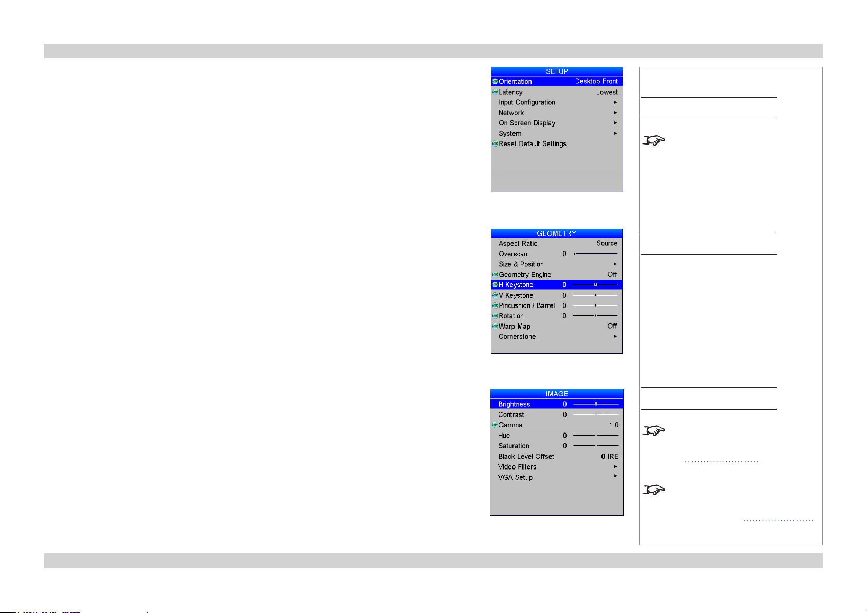
Adjusting the image
Orientation
• This can be set from the Setup menu.
Select the orientation which suits the positioning of the projector.
Keystone
• This can be set from the Geometry menu.
Notes
Main Menu
Setup
Lens shift works from the audience’s
perspective, regarless of projector
orientation. For example, SHIFT UP
moves the image toward the ceiling
in both Desktop and Ceiling mode.
Main Menu
Geometry
Picture
• Settings such as Brightness and Contrast can be set from the Image menu.
• Settings can be accessed from the remote control as well. Depending on the remote you are using:
• On 105-023 Rev B, press BRI, CON or GAMMA to set Brightness, Contrast or Gamma
respectively.
• On 105-023 Rev A, press BRI, CON or SAT to set Brightness, Contrast or Saturation
respectively.
Main Menu
Image
For full details of how to use the
controls and the menu system, see
the Operating Guide.
For further information about the two
remote control devices supported by
the projector, see Remote Control
earlier in this guide.
21Rev D July 2014
Page 30

Digital Projection Lightning Series Installation and Quick-Start Guide
This page is intentionally left blank.
22
Page 31

Lightning Series
High Brightness Digital Video Projector
CONNECTION GUIDE
Rev D July 2014
Page 32

Digital Projection Lightning Series IN THIS GUIDE Connection Guide
IN THIS GUIDE
Signal Inputs And Outputs ............................................................................. 25
Rear Connection Panel .............................................................................................25
VGA (input 1) ....................................................................................................25
HDMI (input 2), DVI (input 3) .............................................................................25
SPDIF .............................................................................................................................25
3G-SDI (input 4) ................................................................................................25
CVBS1 (input 5) ................................................................................................25
S-Video (input 6) ...............................................................................................25
Component (input 7) ..........................................................................................25
CVBS2 (input 8) ................................................................................................25
Side Connection Panel on 3D projectors ................................................................26
DVI (input 9) .....................................................................................................26
DVI/HDMI (input 10) ..........................................................................................26
Special considerations when using Inputs 9-11 ....................................................27
Differences between Inputs 9-11 and Inputs 1-8.............................................................27
Input and processing architecture ...................................................................................27
EDID on the DVI and VGA inputs .............................................................................28
Using HDMI/DVI switchers with the projector .................................................................28
DVI Input connection example .................................................................................29
3D connections .........................................................................................................30
3D sources up to 60Hz requiring frame doubling and left/right interleaving ...................30
3D sources above 60Hz not requiring frame doubling ....................................................30
Dual Pipe 3D ...................................................................................................................30
3D Sync in .......................................................................................................................30
3D Sync out ....................................................................................................................30
3D connection examples .................................................................................................31
RS232 .........................................................................................................................32
LAN .............................................................................................................................32
Update port ................................................................................................................32
LAN connection examples .......................................................................................33
RS232 connection example ......................................................................................34
Control Connections ........................................................................................ 32
Service port ...............................................................................................................32
Wired remote control ................................................................................................32
Rev D July 2014
Page 33

Digital Projection Lightning Series SIGNAL INPUTS AND OUTPUTS Connection Guide
Signal Inputs And Outputs
Rear Connection Panel
VGA (input 1)
• Use Auto Setup in the Image/VGA Setup menu.
HDMI (input 2), DVI (input 3)
Analog or Digital DVI-I
• Set DVI-I Port in the Setup/Input Conguration menu to choose between
Analog and Digital.
SPDIF
• Compatible audio sample packets on the HDMI input stream are decoded by
the projector and output on the SPDIF connector. This is a digital output.
3G-SDI (input 4)
• If two video streams are being transmitted, set 3G Level B Stream in the
Setup/Input Conguration menu to choose between the two streams.
CVBS1 (input 5)
• Connect a Composite Video input signal to the BNC connector.
S-Video (input 6)
• Connect to the 4-pin mini-DIN connector.
Component
DVI
Notes
For more VGA settings, see Image
menu in the Operating Guide.
For further information on setting
up the DVI inputs, see Input
Configuration in the Operating
Guide.
For a complete listing of pin
congurations for all signal and
control connectors, see Wiring
Details in the Reference Guide.
See Side Connection Panel on 3D
projectors for important information
about the differences between the
two connection panels.
Component (input 7)
RGsB or RGBS
• Set Component Colour Space in the Setup/Input Conguration menu
to RGB.
• Set Component Sync Type to Auto, except when the projector has
problems selecting between 3 Wire (RGsB) and 4 Wire (RGBS).
YPbPr
• Set Component Colour Space in the Setup/Input Conguration menu to
YPbPr.
CVBS2 (input 8)
• Connect a Composite Video input signal to the RCA phono connector.
VGA
HDMI
SPDIF
CVBS1
CVBS2
S-Video
3G-SDI
Rear Connection Panel
25Rev D July 2014
Page 34

Digital Projection Lightning Series SIGNAL INPUTS AND OUTPUTS Connection Guide
Side Connection Panel on 3D projectors
DVI (input 9)
• Single or Dual Link DVI-D input, or
• For Twin-Link DVI, Input 9 (DVI) is the Main input, Input 10 (DVI/HDMI)
is the Sub input.
DVI/HDMI (input 10)
• Single HDMI 1.4 input, or
• Single Link DVI-D input, or
• For Twin-Link DVI, Input 9 (DVI) is the Main input, Input 10 (DVI/HDMI)
is the Sub input.
Notes
For a complete listing of pin
congurations for all signal and
control connectors, see Wiring
Details in the Reference Guide.
For information about 3D video, see
the next page.
For information about the
differences between the two
connection panels, see Input
Connections in the Reference
Guide.
DVI
Input 9
together:
Twin-LInk
DVI
Side Connection Panel
DVI/HDMI
Input 10
26Rev D July 2014
Page 35

Digital Projection Lightning Series SIGNAL INPUTS AND OUTPUTS Connection Guide
Special considerations when using Inputs 9-11
Differences between Inputs 9-11 and Inputs 1-8
Inputs 9 and 10 have been designed to offer access to a very high bandwidth digital video path, free of the limitations inherent to standard
image processing techniques. As such, the image is pixel-mapped directly to each DMD™, so only a subset of the image settings applies to
Inputs 9-11.
Global settings, such as input selection, lens and lamp control are all applicable to Inputs 9-11 but modal settings are not.
Input and processing architecture
Front End Processor
Video
Processing
&
Resizing
Inputs 1-8
OSD
Overlay
Multi Standard Inputs:
Analog & Digital
24-60 Hz
Frame Doubling Memory
3D MUX
Inputs 9, 10 and 11
3D Back End
DMD Formatting
High Bandwidth
Digital Path
“Pixel Mapped”
Notes
There is no scaler on Inputs 9-11.
Images up to and including the
native resolution of the display will
be displayed pixel for pixel and
centred.
This enables the projector to
maximise the image bandwidth and
grayscale resolution.
Global settings are indicated by
a globe icon in the OSD and affect
all inputs.
Modal settings only affect the
currently displayed input.
3D sync
27Rev D July 2014
Page 36

Digital Projection Lightning Series SIGNAL INPUTS AND OUTPUTS Connection Guide
EDID on the DVI and VGA inputs
If you are using a computer DVI card or another source that obeys the EDID protocol, the source will automatically congure itself to suit the
projector.
Otherwise please refer to the documentation supplied with the source to manually set the resolution to the DMD™ resolution of the projector
or the nearest suitable setting. Switch off the source, connect to the projector, then switch the source back on again.
Using HDMI/DVI switchers with the projector
When using an HDMI/DVI source switcher with the projector, it is important to set the switcher so that it passes the projector EDID through to
the source devices. If this is not done, the projector may not be able to lock to the source or display the source correctly as its video output
timings may not be compatible with those of the projector. Sometimes this is called transparent, pass-through or clone mode. See your
switcher’s manual for information on how to set this mode.
Additionally, sources which use HDCP encryption may not display properly when connected to the projector via a switcher. Refer to the
switcher’s manual for more information.
1 32
1
Sources
2
Switcher
3
Projector
EDID
EDID
EDID
EDID
Notes
The EDIDs in the switcher should be the same as the one in the projector.
28Rev D July 2014
Page 37

Digital Projection Lightning Series SIGNAL INPUTS AND OUTPUTS Connection Guide
DVI Input connection example
Single link DVI video source
Single or Dual link
DVI video source
Single link
DVI or HDMI video source
Dual Pipe 3D video source
Input 3
Input 9
Input 10
Input 11: Input 9 MAIN and Input 10 SUB
Notes
Dual link DVI:
high bandwidth/frame rate
29Rev D July 2014
Page 38

Digital Projection Lightning Series SIGNAL INPUTS AND OUTPUTS Connection Guide
3D connections
3D sources up to 60Hz requiring frame doubling and left/right interleaving
1. Connect to any of the Inputs on the Rear Connection Panel.
2. Set 3D Type in the 3D menu to match the format of the incoming signal. Choose from
Sequential, Top-and-Bottom and Side-by-Side (Half).
1
3D sources above 60Hz not requiring frame doubling
1. Connect to either of the Inputs on the Side Connection Panel.
2
2. Set 3D Type in the 3D menu to Auto, except when the projector has problems selecting between
Sequential, Frame Packing, Top-and-Bottom and Side-by-Side (Half).
Dual Pipe 3D
3
4
• Connect to both of the Inputs on the Side Connection Panel.
• Input 9 (DVI) is the left image, and Input 10 (DVI/HDMI) is the right image.
3D Sync in
Side Connection Panel
• Sync input signal.
3D Sync out
• Sync output signal. This may be affected by the Sync Offset and Output Sync Polarity settings in the 3D menu
SIDE CONNECTION PANEL:
1
DVI (Input 9)
2
DVI/HDMI (input 10)
3
3D Sync In
4
3D Sync Out
5
Dual Pipe 3D (Input 9 and 10 together)
Notes
For a complete listing of pin
congurations for all signal and
control connectors, see Wiring
Details in the Reference Guide.
5
76
3D SYNC:
6
3D input
7
3D Sync In
8
3D glasses or ZScreen
9
3D Sync Out
8 9
30Rev D July 2014
Page 39

Digital Projection Lightning Series SIGNAL INPUTS AND OUTPUTS Connection Guide
3D connection examples
3D sources up to 60Hz, requiring frame doubling and left/right interleaving
Video
Inputs 1-11
Sync
3D server
3D sources above 60Hz
Notes
Use inputs 1-8 if the geometry of the
image needs to be adjusted.
For more information on 3D settings,
see the 3D Setup section further in
this guide.
Sync outSync in
ZScreen or IR emitter
3D server
Video
Sync
Input 9
ZScreen or IR emitter
31Rev D July 2014
Page 40

Digital Projection Lightning Series CONTROL CONNECTIONS Connection Guide
Control Connections
Service port
• The Service Port port is used to download, via USB, rmware updates
issued from time to time by Digital Projection.
Wired remote control
• If infrared signals from the remote control cannot reach the projector
due to excessive distance or obstructions such as walls or cabinet
doors, you can connect an external IR repeater to the remote control
input, and position its IR sensor within range of the operator.
• To synchronise the control of multiple projectors, connect the wired
remote output of one projector to the wired remote input of another.
RS232
• All of the projector’s features can be controlled via a serial connection,
using the text strings described in the Protocol Guide.
• Use a null-modem cable to connect directly to a computer, or a straight
cable to connect to a modem.
LAN
• All of the projector’s features can be controlled via a LAN connection,
using the text strings described in the Protocol Guide.
• Alternatively, use the Virtual OSD to control the projector.
• Use a crossed LAN cable to connect directly to a computer, or an
uncrossed cable to connect to a network hub.
Update port
• The Update Port is used to download, via LAN, rmware updates issued
from time to time by Digital Projection.
Update
Port
Wired Remote
Input
Wired Remote
Output
RS232
Service
Port
Notes
For a complete listing of pin
congurations for all signal and
control connectors, see Wiring
Details in the Reference Guide.
For a list of all commands used to
control the projector via LAN or a
serial connection, see the Protocol
Guide.
For details on using the Virtual OSD,
see Virtual OSD in the Protocol
Guide.
For further information about
LAN connectivity, see Control
Connections in the Reference
Guide.
Only one remote connection (RS232
or LAN) should be used at any one
time.
Plugging in the remote control cable
will disable the infrared receivers.
LAN
Rear Connection Panel
32Rev D July 2014
Page 41

Digital Projection Lightning Series CONTROL CONNECTIONS Connection Guide
LAN connection examples
Crossed LAN cable
Computer
Un-crossed LAN cables
Hub or LAN
Notes
For further information on using a
network connection to control the
projector, see the Protocol Guide.
Projector
1
Computer
Rear
connection
panel
Projector
Projector
1
LAN
33Rev D July 2014
Page 42

Digital Projection Lightning Series CONTROL CONNECTIONS Connection Guide
RS232 connection example
Null-modem cable
Computer
Projector
Notes
1
Rear
connection
panel
1
RS232
34Rev D July 2014
Page 43

Lightning Series
High Brightness Digital Video Projector
OPERATING GUIDE
Rev D July 2014
Page 44

Digital Projection Lightning Series IN THIS GUIDE Operating Guide
IN THIS GUIDE
Using The Menus ............................................................................................... 37
Menus and sub-menus .............................................................................................37
Drop-down lists .........................................................................................................38
Sliders ........................................................................................................................39
Commands .................................................................................................................39
Editing elds ..............................................................................................................40
Using The Projector ......................................................................................... 41
Lens menu .................................................................................................................42
Zoom ...............................................................................................................................42
Focus ..............................................................................................................................42
Calibrate Zoom and Calibrate Focus ..............................................................................42
Center Lens ....................................................................................................................42
Nudge .............................................................................................................................42
Lens Presets ...................................................................................................................43
Image menu ...............................................................................................................44
Video Filters ....................................................................................................................44
VGA Setup ......................................................................................................................44
Color menu ................................................................................................................45
Gamut .............................................................................................................................45
Black Level and Gain sliders ...........................................................................................45
Geometry menu .........................................................................................................46
Aspect Ratio ....................................................................................................................46
Overscan .........................................................................................................................46
Size & Position ................................................................................................................47
Blanking ..........................................................................................................................47
Geometry Engine ............................................................................................................48
Edge Blend menu ......................................................................................................54
Overview .........................................................................................................................54
Array Width and Height ...................................................................................................55
Array H Position and V Position ......................................................................................55
S-Curve Value .................................................................................................................56
Blending ..........................................................................................................................58
Segmentation ..................................................................................................................59
Blend Width .....................................................................................................................61
Black Level Uplift ............................................................................................................61
Reduce Black Level Uplift Width .....................................................................................62
Blending images from multiple projectors .............................................................63
Before you start ...............................................................................................................63
Edge Blend procedure ....................................................................................................64
PIP menu ....................................................................................................................72
3D menu .....................................................................................................................73
3D types ..........................................................................................................................74
Some 3D settings explained ....................................................................................76
Dark Time ........................................................................................................................76
Source Dominance .........................................................................................................76
Sync Offset......................................................................................................................76
Frame Rate Multiplier ......................................................................................................77
Lamp menu ................................................................................................................78
Setup menu ................................................................................................................79
Reset Default Settings ....................................................................................................79
Input Conguration ..........................................................................................................80
Network ...........................................................................................................................81
On Screen Display ..........................................................................................................82
System ............................................................................................................................83
Setting up an IR address ................................................................................................84
Information menu ......................................................................................................85
Conguration ...................................................................................................................85
Rev D July 2014
Page 45

Digital Projection Lightning Series USING THE MENUS Operating Guide
Using The Menus
Use the buttons on the projector control panel or on the remote control, to access the menu system.
• To open or close the on-screen display (OSD), press MENU.
Menus and sub-menus
• To open a sub-menu, select it using the UP and DOWN arrow buttons, then press OK.
• To return to the previous menu, press EXIT.
Notes
Some menu items may not be
available due to settings in other
menus. These will be grayed out on
the actual menu.
When a globe icon appears next
to a setting, the setting affects all
sources and all inputs; otherwise,
only the current input source will be
affected if you change the setting.
37Rev D July 2014
Page 46

Digital Projection Lightning Series USING THE MENUS Operating Guide
Drop-down lists
To use a drop-down list:
1. Navigate to the drop-down list in the menu and
press OK.
2. Highlight an item from the list using
the UP and DOWN arrow buttons.
Notes
Some menu items may not be
available due to settings in other
menus. These will be grayed out on
the actual menu.
When a globe icon appears next
to a setting, the setting affects all
sources and all inputs; otherwise,
only the current input source will be
affected if you change the setting.
3. Press OK again to select the highlighted item, or
press EXIT to exit without changing.
38Rev D July 2014
Page 47

Digital Projection Lightning Series USING THE MENUS Operating Guide
Sliders
To use a slider, press the LEFT and RIGHT arrow buttons to adjust it.
Commands
To use a command, press OK. In the example below, press OK to conrm, or press EXIT to cancel.
Notes
Some menu items may not be
available due to settings in other
menus. These will be grayed out on
the actual menu.
When a globe icon appears next
to a setting, the setting affects all
sources and all inputs; otherwise,
only the current input source will be
affected if you change the setting.
39Rev D July 2014
Page 48

Digital Projection Lightning Series USING THE MENUS Operating Guide
Editing elds
Some features require a text or numeric eld to be edited.
1. To edit a eld, rst select it using the LEFT and RIGHT arrow buttons, then press OK.
2. Use the LEFT and RIGHT arrow buttons to move the green highlight to the digit or character which is to be changed, then use
UP and DOWN to adjust it.
3. Use the LEFT and RIGHT arrow buttons to select the next digit or character.
4. Press OK to accept the new value, or press EXIT to exit without changing.
The highlighted digit is being edited
Notes
Some menu items may not be
available due to settings in other
menus. These will be grayed out on
the actual menu.
40Rev D July 2014
Page 49

Digital Projection Lightning Series USING THE PROJECTOR Operating Guide
Using The Projector
Main menu
• Input Selection
Select an input source from the drop-down list.
• Test Pattern
Set Input Selection to Test Patter n and then select a test pattern from the drop-down list.
• Lens, Image, Color and Geometry
Open these sub-menus to access various picture and screen settings.
• Edge Blend / PIP
PIP and Edge Blend are mutually exclusive modes of operation. When the projector is in Edge
Blend mode (as shown in the picture), PIP is not available, and vice versa.
• 3D
Access 3D settings.
• Lamp
Adjust lamp power.
• Setup
Adjust Input Conguration, Network, On Screen Display and System settings.
• Information
View your current conguration
Notes
See also Using the Menus earlier in
this guide and Appendix D: Menu
Map in the Reference Guide.
Main Menu
You can also select an input source
by pressing the following buttons on
the remote control: 1 to 9 for inputs
1 to 9, 10+ for input 10 and # for
input 11.
Test patterns are subject to image
controls, so brightness, contrast
etc. will affect their appearance on
screen.
Do not use the provided test
patterns for P7.
You can upload custom test patterns
using a network connection - see
Virtual OSD in the Protocol Guide.
The 3D menu is not available with
2D projectors.
41Rev D July 2014
Page 50

Digital Projection Lightning Series USING THE PROJECTOR Operating Guide
Lens menu
Zoom
To move the lens in or out:
1. Select Zoom In or Zoom Out, then press OK.
2. When the image is the desired size, select Zoom Stop then press OK.
Focus
To adjust the focus:
1. Select Focus Near or Focus Far, then press OK.
2. When the image is correctly focussed, select Focus Stop then press OK.
Calibrate Zoom and Calibrate Focus
Each time a new lens is tted into the projector, a calibration procedure must be carried out using
these commands.
Before you use a newly tted lens, select Calibrate Zoom and Calibrate Focus in turn and wait until
the projector establishes minimum and maximum travel distances. Select one command and allow at
least 60 seconds for the calibration to take place, then select the other command.
Center Lens
To center the lens, select Center Lens and press OK.
Nudge
To position the image correctly on the screen, use the Nudge controls.
Notes
Main Menu
Lens
You can also move the lens, focus
and zoom using the keypad:
• Press SHIFT followed by an
arrow button to shift the lens up,
down, left and right.
• Press FOCUS followed by the
UP and DOWN arrow buttons to
adjust the focus.
• Press ZOOM followed by the
UP and DOWN arrow buttons to
zoom in and out.
You can also calibrate zoom and
focus using the keypad:
• Press RPY followed by the
RIGHT arrow button to calibrate
the lens zoom mechanism.
• Press RPY followed by the
LEFT arrow button to calibrate
the lens focus mechanism.
Main Menu
Lens
Nudge
42Rev D July 2014
Page 51

Digital Projection Lightning Series USING THE PROJECTOR Operating Guide
Lens Presets
This menu allows you to save up to ve custom lens presets, which you can recall later.
Notes
Main Menu
Lens
Lens Presets
43Rev D July 2014
Page 52

Digital Projection Lightning Series USING THE PROJECTOR Operating Guide
Image menu
• Brightness, Contrast, Gamma, Hue and Saturation
Set the slider or select from the drop-down list as required, to improve the quality of the image.
• Black Level Offset
Set this to 0 IRE or 7.5 IRE as required.
• Use V Position and H Position to adjust the position manually.
Video Filters
Set the sliders or select from the drop-down list as required, to improve the quality of the image.
Notes
Main Menu
Image
You can also press BRI, CON or
SAT on the remote control.
Hue applies only to NTSC signals.
When a new input mode is detected
(eg NTSC, HDTV 1080p, SVGA etc),
all the Input Settings are saved so
that they can be recalled next time
that input mode is displayed.
Main Menu
Image
Video Filters
VGA Setup
Use Auto Setup to allow the projector to detect the appropriate settings automatically.
If you require manual adjustment:
• Set the Phase slider to correct for shimmering or poor quality denition on, for example, ne text.
• Set the Total H Samples slider to match the resolution of the incoming video signal.
Main Menu
Image
VGA Setup
VGA Setup is not available unless
a VGA signal is present.
44Rev D July 2014
Page 53

Digital Projection Lightning Series USING THE PROJECTOR Operating Guide
Color menu
Gamut
Peak gives you the brightest possible image.
Choose HDTV for high denition standards and SDTV for standard denition standards.
A value between 3200K and 9000K selects the relevant color temperature.
You can upload your own gamut using the Projector Manager software, and then select it from
the User 1 and User 2 settings.
Black Level and Gain sliders
Set the sliders as required.
Notes
Main Menu
Color
45Rev D July 2014
Page 54

Digital Projection Lightning Series USING THE PROJECTOR Operating Guide
Geometry menu
Aspect Ratio
Choose between Source, Fill Display, Fill & Crop, Anamorphic and TheaterScope.
Some devices (eg certain DVD players) pack a 16:9 image into a 4:3 aspect ratio. In such cases to
display the image correctly, choose the Anamorphic aspect ratio.
Overscan
Set this slider to compensate for noisy or badly dened image edges.
Notes
Main Menu
Geometry
An anamorphic lens (optional
accessory) is used with the
TheaterScope setting, to ensure
that for a 2.35:1 image, the
maximum area of the DMD is used,
giving maximum image brightness.
For examples of how the different
aspect ratios affect screen
dimensions, see Aspect Ratios
Explained in the Reference Guide.
Items on this page may be
unavailable depending on the
Geometry Engine setting.
Image with noisy edges Overscanned image
46Rev D July 2014
Page 55

Digital Projection Lightning Series USING THE PROJECTOR Operating Guide
Size & Position
• Set Enable to On or Off.
• Use Setting to choose:
Global, in which case these settings will be applied to all signals on all inputs.
or Per Mode, in which case these settings will be applied only to the current input signal.
• Set the H Position and V Position sliders as required.
• Set H Size and V Size. When Aspect Lock is set to On, the V Size slider is disabled.
• Select Reset and press OK to reset all the sliders.
Blanking
Blanking curtains can be applied to each edge of the projected image.
• Set Enable to On or Off.
• Set the sliders as required.
Notes
Main Menu
Geometry
Size & Position
Main Menu
Geometry
Blanking
47Rev D July 2014
Page 56

Digital Projection Lightning Series USING THE PROJECTOR Operating Guide
Geometry Engine
Choose from Keystone, Cornerstone, Rotation, Warp or Off.
• If Geometry Engine is set to Keystone, set the H Keystone and V Keystone sliders to correct
for any distortion caused by the projector being in a different horizontal or vertical plane to the
screen.
Notes
Main Menu
Geometry
Some items on this menu may
be unavailable depending on the
Geometry Engine setting.
If possible, position the projector
facing the screen at a right angle to
avoid geometry corrections.
1 2 3
1
The projector is positioned at an angle
2
The resulting image is distorted
3
The image is corrected when Keystone is applied
48Rev D July 2014
Page 57

Digital Projection Lightning Series USING THE PROJECTOR Operating Guide
Geometry Engine (continued)
Keystone settings
1
Projector to the left
The projector is positioned
to the left of the screen.
To correct, apply a positive
H Keystone value using
the RIGHT arrow button.
2
Projector to the right
The projector is positioned
to the right of the screen.
To correct, apply a negative
H Keystone value using
the LEFT arrow button.
3
Projector high
The projector is positioned
above the screen at a
downward angle.
To correct, apply a negative
V Keystone value using
the LEFT arrow button.
4
Projector low
The projector is positioned
below the screen at an
upward angle.
To correct, apply a positive
V Keystone value using
the RIGHT arrow button.
Notes
Main Menu
Geometry
1
2
If possible, position the projector
facing the screen at a right angle to
avoid geometry corrections.
5
Projector straight
The projector is directly
opposite the screen at a
right angle both horizontally
and vertically.
No correction is needed.
4
53
Horizontal and vertical keystone corrections
49Rev D July 2014
Page 58

Digital Projection Lightning Series USING THE PROJECTOR Operating Guide
Geometry Engine (continued)
• Pincushion / Barrel is enabled if Geometry Engine is set to Keystone or Rotation.
Set the slider to correct for any distortion caused by the screen being concave or convex.
Notes
Main Menu
Geometry
Some items on this menu may
be unavailable depending on the
Geometry Engine setting.
If possible, position the projector
facing the screen at a right angle to
avoid geometry corrections.
Pincushion Barrel
50Rev D July 2014
Page 59

Digital Projection Lightning Series USING THE PROJECTOR Operating Guide
Geometry Engine (continued)
• If Geometry Engine is set to Rotation, set the Rotation slider to rotate the image on the screen.
1
DMD position
The DMD is not rotated.
2
Area outside DMD
The corners of the rotated image leave the
DMD and appear cropped.
3
Angle of rotation
The angle equals the Rotation setting.
In this example the angle is 25°, therefore
Rotation = 25.
1
2
Notes
Main Menu
Geometry
Some items on this menu may
be unavailable depending on the
Geometry Engine setting.
If possible, position the projector
facing the screen at a right angle to
avoid geometry corrections.
3
51Rev D July 2014
Page 60

Digital Projection Lightning Series USING THE PROJECTOR Operating Guide
Geometry Engine (continued)
Warp Map
Using DP Warp Generator, an external Digital Projection computer application, up to eight
customised warp maps can be created and uploaded to the projector. If Geometry Engine is set to
Warp, and any warp maps have been uploaded, you can select from the drop-down list.
Notes
Main Menu
Geometry
Some items on this menu may
be unavailable depending on the
Geometry Engine setting.
If possible, position the projector
facing the screen at a right angle to
avoid geometry corrections.
1
Distorted image
The image is projected on an uneven surface.
2
Warp map
The map mirrors the surface - raised areas on the surface correspond to hollow areas on the map, and vice versa.
3
Corrected image
With the warp map applied, the projector compensates for the surface and the projected image appears undistorted.
1
2 3
52Rev D July 2014
Page 61

Digital Projection Lightning Series USING THE PROJECTOR Operating Guide
Geometry Engine (continued)
Cornerstone
If Cornerstone is selected from the main Geometr y page, you can use
the sliders to stretch the image from each of the four corners.
Notes
Main Menu
Geometry
Cornerstone
Upper Right X and Upper Right Y correction
53Rev D July 2014
Page 62

Digital Projection Lightning Series USING THE PROJECTOR Operating Guide
Edge Blend menu
The Edge Blend menu is available only when Setup >
System > Conguration is set to Edge Blend.
Overview
When several projectors are used to create a large tiled
image, the edges need to be blended to avoid the overlaps
appearing brighter than the rest of the image.
As it is not possible for any projector to produce an
absolute black, any ‘black’ areas in the overlapped edges
may appear slightly less dark than those in the rest of the
image. Black Level Uplift can be used to counteract this
effect, by raising the black level of the rest of the image.
The amount of uplift required will be either x2 or x4,
depending on how many images are overlapped, as shown
in the examples on this page.
Image brightness changes from one point to another,
within the same blended region. If the same level of black
level uplift is applied throughout the blended region, the
overlapping edges may still be visible on the screen.
Therefore, brightness in these areas is decreased
gradually, using an s-curve factor. S-Curve Value is used
to control the steepness of the decrease.
1 2
Two projectors sharing one overlapping edge
3
21
1
x2 uplift area
2
no uplift
Notes
Main Menu
Edge Blend
This menu is available only when
Setup > System > Conguration is
set to Edge Blend.
None of the other items in this menu
are available until either the Array
Width or the Array Height setting
is greater than 1.
The position numbering starts from
zero, so the top left projector is at
position H 0, V 0.
Which settings are available in these
menus depends on:
● the number of projectors in the
array
● the position of the projector in
the array
An image like the one shown here
can be produced by an array of 16
projectors only if Segmentation
is set to ON, or if an external tool
is used to split the image into
segments. See Segmentation
further in this section.
Four projectors with overlapping edges
1
x4 uplift area
2
x2 uplift area
3
no uplift
54Rev D July 2014
Page 63

Digital Projection Lightning Series USING THE PROJECTOR Operating Guide
Array Width and Height
• Set this to the total number of projectors in the array. None of the other
options are available until one of these two settings is greater than 1.
The maximum number of projectors is 4 x 4.
Array H Position and V Position
• These two parameters need to be set correctly for each projector
in the array, so that it can determine which edges are to be blended.
Sometimes only one edge overlaps, sometimes two, three or four.
Example
The illustration shows an array of sixteen projectors. Array Width and
Array Height of all projectors have been set up as follows:
Array H Position: 0 to 3
• Array Width = 4
• Array Height = 4
Array H Position and Array V Position of each projector have been set
up to reect its vertical and horizontal position in the array.
The settings for the third projector in the second row 1 are:
Array V Position: 0 to 3
1
• Array H Position = 2
• Array V Position = 1
Example array of sixteen projectors
Notes
Main Menu
Edge Blend
This menu is available only when
Setup > System > Conguration is
set to Edge Blend.
None of the other items in this menu
are available until either the Array
Width or the Array Height setting
is greater than 1.
The position numbering starts from
zero, so the top left projector is at
position H 0, V 0.
Which settings are available in these
menus depends on:
● the number of projectors in the
array
● the position of the projector in
the array
An image like the one shown here
can be produced by an array of 16
projectors only if Segmentation
is set to ON, or if an external tool
is used to split the image into
segments. See Segmentation
further in this section.
55Rev D July 2014
Page 64

Digital Projection Lightning Series USING THE PROJECTOR Operating Guide
S-Curve Value
• In the regions where two or more projectors overlap, the brightness of the signal is decreased to
blend the images. S-Curve Value controls the steepness of this decrease.
Notes
Main Menu
Edge Blend
This menu is available only when
Setup > System > Conguration is
set to Edge Blend.
None of the other items in this menu
are available until either the Array
Width or the Array Height setting
is greater than 1.
1
Y = amount of light
X = distance from the edge (X=0 is the edge)
56Rev D July 2014
Page 65

Digital Projection Lightning Series USING THE PROJECTOR Operating Guide
S-Curve Value (continued)
When images overlap, the area of overlap receives light from all overlapping sources. Without S-Curve, the overlapping edges would be
brighter than the rest of the image, as shown in Fig. 1.
Fig. 1: Overlapping edges without S-Curve
If two reciprocal S-Curves are used to control the amount of light from each source in the overlapping region, the total amount of light in the
region would remain constant, as shown in Fig. 2.
Notes
Main Menu
Edge Blend
This menu is available only when
Setup > System > Conguration is
set to Edge Blend.
None of the other items in this menu
are available until either the Array
Width or the Array Height setting
is greater than 1.
Fig. 2: Applying S-Curve to overlapping edges
57Rev D July 2014
Page 66

Digital Projection Lightning Series USING THE PROJECTOR Operating Guide
Blending
This setting enables s-curve blending, or displays an align pattern to help dene
overlaps between segments.
Set Blending to:
1
Off
Edge Blend is not used.
2
On
S-curves are enabled in the overlapping regions.
3
Align Pattern
The align pattern makes the overlaps more visible and helps adjust the
physical position of the projectors in the array.
The size of the align pattern is controlled by the Blend Width group of
settings.
Notes
Main Menu
Edge Blend
This menu is available only when
Setup > System > Conguration is
set to Edge Blend.
None of the other items in this menu
are available until either the Array
Width or the Array Height setting
is greater than 1.
1
2
3
58Rev D July 2014
Page 67

Digital Projection Lightning Series USING THE PROJECTOR Operating Guide
Segmentation
Segmentation can be used if the same image is fed into each projector.
• If Segmentation is Off, every projector in the array will display the whole image.
• If this setting is On, each projector will display its own segment only.
Set to Off if you have external software that handles segmentation.
Notes
Main Menu
Edge Blend
This menu is available only when
Setup > System > Conguration is
set to Edge Blend.
None of the other items in this menu
are available until either the Array
Width or the Array Height setting
is greater than 1.
Segmentation off
Segmentation on
59Rev D July 2014
Page 68

Digital Projection Lightning Series USING THE PROJECTOR Operating Guide
Segmentation (continued)
An example array:
Notes
Main Menu
Edge Blend
2 31
1
Image source
DVD player, Blu-Ray, computer, etc.
2
Distribution Amplier
Sends the source image to all projectors in the array.
3
Array (Segmentation is on)
Each projector displays a segment.
60Rev D July 2014
Page 69

Digital Projection Lightning Series USING THE PROJECTOR Operating Guide
Blend Width
Use this to set the width of the blended regions.
1
Top Blend Region
2
Bottom Blend Region
3
Left Blend Region
4
Right Blend Region
Black Level Uplift
Overlapping edges may appear lighter than the rest
of the image. Counteract this effect by raising black
levels in the rest of the image. The amount of uplift
required will be either x2 or x4, depending on how
many images are overlapped.
The following example shows a segment with
overlapping edges on all sides.
1 2
Notes
To apply the settings in these
menus, use the Apply command at
the bottom of each page.
Main Menu
Edge Blend
Blend Width
3
4
75 6
Main Menu
Edge Blend
Black Level Uplift
5
Unblended Region
This region is not overlapped. Black level
should be raised by the maximum overlap
occurring within the segment, therefore
Black Level Uplift should be x4.
6
Upper Middle
This section of the image is overlapped
by two projectors, therefore the correct
amount of Black Level Uplift should be
x2.
7
Upper Right
This part of the image is overlapped by
four projectors, therefore Black Level
Uplift should not be applied.
61Rev D July 2014
Page 70

Digital Projection Lightning Series USING THE PROJECTOR Operating Guide
Reduce Black Level Uplift Width
Use this to correct for stray light from the pond of mirrors, the DMD’s inactive outermost mirrors.
In the example below, the blended image comes from two projectors, 1 and 2. Both images
have black level uplift applied in their unblended regions; as a result, artifacts 3 and 4 have
emerged at the edges where the black level uplift region of one projector overlaps the pond of mirrors
of the other.
To remove the artifcats, you need to slightly reduce the size of the black level uplift region of each
projector so it does not overlap the pond of mirrors of the other projector.
1 2
Notes
Main Menu
Edge Blend
Reduce Black Level Uplift Width
To apply the settings in this menu,
use the Apply Uplift command at
the bottom of the page.
For additional information, see The
DMD™ in the Reference Guide.
For a detailed step-by-step
description of the edge blend
process, see Blending images
from multiple projectors further in
this section.
3 4
62Rev D July 2014
Page 71

Digital Projection Lightning Series USING THE PROJECTOR Operating Guide
Reduce Black Level Uplift Width (continued)
A detailed view of one of the projectors in a
two-projector array:
Black level uplift region
1
This image occupies the left half of a
two-projector array. Black level uplift
has created artifacts on the edges of
the blend region.
Artifact (left)
2
This artifact is caused by the
other projector’s pond of mirrors
overlapping the black level uplift
region of this projector. It can be
eliminated if the black level uplift
width of this projector is reduced.
Blend region
3
The area in the middle of the array,
where the two images overlap.
Black level uplift has not been
applied here.
Artifact (right)
4
This artifact is caused by this
projector’s pond of mirrors
overlapping the black level uplift
region of the other projector. It
can be eliminated if the black level
uplift width of the other projector is
reduced.
1 2 3 4
Notes
Main Menu
Edge Blend
Reduce Black Level Uplift Width
For additional information, see The
DMD™ in the Reference Guide.
For a detailed step-by-step
description of the edge blend
process, see Blending images
from multiple projectors further in
this section.
63Rev D July 2014
Page 72

Digital Projection Lightning Series USING THE PROJECTOR Operating Guide
Reduce Black Level Uplift Width (continued)
In the Reduce Black Level Uplift
Width menu, settings correspond
to coordinates within the unblended
regions. Only relevant coordinates
are enabled.
To remove the artifact on the left:
1. Open the Reduce Black Level
Uplift Width menu of the
projector on the left.
2. Adjust Upper Right X and
Lower Right X.
3. Select Apply Uplift. The
black level uplift region of this
projector will withdraw from the
pond of mirrors of the other
projector and the artifact will
disappear.
To remove the artifact on the right,
• Open the Reduce Black
Level Uplift Width menu
of the projector on the right
and adjust Upper Left X and
Lower Left X, then select
Apply Uplift.
Notes
Main Menu
Edge Blend
Reduce Black Level Uplift Width
To apply the settings in this menu,
use the Apply Uplift command at
the bottom of the page.
For additional information, see The
DMD™ in the Reference Guide.
For a detailed step-by-step
description of the edge blend
process, see Blending images
from multiple projectors further in
this section.
64Rev D July 2014
Page 73

Digital Projection Lightning Series USING THE PROJECTOR Operating Guide
Blending images from multiple projectors
The following procedure explains how to set up an array of projectors and how to blend the images together.
Before you start
Position the projectors
Ensure that all projectors are in good working order.
Position the projectors so that they are within the required throw distance range. Position the screen where it will remain during operation.
In the initial stages of the procedure you will be using test patterns, therefore it is not necessary to connect the input at this stage. However,
you need to make sure that you are able to connect the inputs without moving the projectors.
Control the projectors
You can control the projectors individually by using:
• their respective control panels, or
• a dedicated remote control for each projector, or
• a single remote control for all projectors. To do so, you need to assign a different IR address for each projector.
Consider connecting the projectors in a LAN network and using the Projector Controller application to monitor the projectors and change
settings on the whole array at once.
Notes
For information about changing
the IR address of a projector, see
Setting up an IR address further in
this guide.
The Projector Controller software
is available for download from the
Digital Projection website, free of
charge.
65Rev D July 2014
Page 74

Digital Projection Lightning Series USING THE PROJECTOR Operating Guide
Edge Blend procedure
1. Align the projectors as they will be used in the array.
Each projector should be perpendicular to the screen, or as close as possible. Ideally, each projector should allow for a minimum of 20%
screen overlap where it is adjoined by other projectors. Overlaps should be the same in size across the array.
How to align the projectors:
• Ideally, all alignment should be achieved by physically moving the projectors and by using the Lens Shift and Zoom functions.
• If necessary, use Image > V Position and H Position.
• Do not use geometry corrections.
321
Example: 1080p projector overlapped on
all sides
1
Overlap to the left
This overlap takes 20% of the image width, or
384 pixels.
2
Overlap to the top
This overlap takes 20% of the image height,
or 216 pixels.
384 pixels
216 pixels
1920 pixels
Notes
3
Area without overlaps
This area is also called unblended region.
1080 pixels
A 1080p projector with 20% overlaps on all sides
66Rev D July 2014
Page 75

Digital Projection Lightning Series USING THE PROJECTOR Operating Guide
Edge Blend procedure (continued)
2. Ensure that all projectors are color-matched.
If necessary, use the White Field test pattern and test the light output of each projector.
Ensure the Color > Gamut setting has the same value across the array.
Use Lamps > Lamp Power to compensate for different lamps. Even identical lamps change their light output with age and use.
1 2
Before color-match
1 2
Notes
1
Projector 1: incorrect settings
Before the color-match this
image has incorrect color gamut
and lamp power settings
2
Projector 2: correct settings
After color-match
3. Enter the correct gamma setting.
Adjust the gamma setting using the Image > Gamma control. For video sources, such as Blu-ray or DVD, use a value of 2.2; for
computer graphics use 2.4.
The images may still look slightly different at this stage. It is OK to continue.
67Rev D July 2014
Page 76

Digital Projection Lightning Series USING THE PROJECTOR Operating Guide
Edge Blend procedure (continued)
4. Set up the array.
For each projector, open the Edge Blend menu and enter Array Width, Array Height, Array H Position and Array V Position.
Array Width and Array Height should be identical for all projectors. These settings dene the size of the array. For example, a two-by-
two array will have the following values:
• Array Width = 2
• Array Height = 2
The top left projector will have Array H Position = 0 and Array V Position = 0.
1
Top left
Array H Position = 0
Array V Position = 0
2
Top right
Array H Position = 1
Array V Position = 0
3
Bottom left
21
Notes
Array H Position = 0
Array V Position = 1
4
Bottom right
Array H Position = 1
Array V Position = 1
3 4
68Rev D July 2014
Page 77

Digital Projection Lightning Series USING THE PROJECTOR Operating Guide
Edge Blend procedure (continued)
5. Dene blend regions.
From the Edge Blend menu on all projectors,
set Blending to Align Pattern.
Set up Blend Width on each projector so
that the align patterns overlap perfectly and
completely cover the blend regions (Fig. 2).
If necessary, physically move the projectors
and/or use Lens Shift and Zoom again to
align the array perfectly
Fig. 2
1
Left projector
2
Align pattern of left projector
The red arrow next to the align pattern
shows what correction needs to be made
for the align pattern to cover the whole
blend region.
3
Blend region
The brighter ribbon in the middle is
overlap area not covered by the align
patterns.
4
Align pattern of right projector
The red arrow next to the align pattern
shows what correction needs to be made
for the align pattern to cover the whole
blend region.
5
Right projector
Fig. 1 Align patterns make it easy to see where the overlap is not perfect
21
4 5
3
Notes
Fig. 2 Projectors with align patterns not covering the blend region
69Rev D July 2014
Page 78

Digital Projection Lightning Series USING THE PROJECTOR Operating Guide
Edge Blend procedure (continued)
6. Uplift black levels (optional).
If you do not need to uplift the black levels, skip
to step 8, Blend the images.
Switch all projectors to the Black Field test pattern.
The level of black will differ across the image as
shown in Fig. 1. Uplift the black levels using Edge
Blend > Black Level Uplift.
How to uplift black levels
Regions may be overlapped by two or four
projectors. An array will always contain regions
overlapped by at least two projectors.
• x2 overlaps
If your array only contains two-projector
overlaps, you need to uplift the black levels in
the unblended regions – the exact value will
depend on the projector, environment, etc.
Do not uplift black levels in the overlapping
region(s).
• x2 and x4 overlaps
Sometimes a region is overlapped by four
projectors. For example, in a two-by-two
segment setup, Array Width = 2 and
Array Height = 2, the region in the middle is
overlapped by all four projectors (as shown in
Fig. 1). If your array contains such regions, you
need to uplift black levels roughly four times in
the unblended regions, and roughly double in
the regions overlapped by two projectors.
1
Unblended region
This region is not overlapped. Black level should be raised by the
maximum overlap occurring within the image, therefore the value of
Black Level Uplift should be the highest here.
2
x2 overlap
This section of the image is overlapped by two projectors, therefore the
correct amount of
uplift within the unblended region.
3
x4 overlap
This part of the image is overlapped by four projectors, therefore
Level Uplift should not be applied.
31 2
Fig. 1 Different black levels
Black Level Uplift should be roughly half the value of
Black
Notes
70Rev D July 2014
Page 79

Digital Projection Lightning Series USING THE PROJECTOR Operating Guide
Edge Blend procedure (continued)
7. Adjust uplift edges (optional).
This step is necessary if you
have uplifted the black levels
in the previous step.
During the black level uplift
process, brighter lines appear on
the edges of the uplifted regions.
This is due to the inactive area
around the periphery of the DMD,
also known as
pond of mirrors 1.
To remove these edges, use the
Edge Blend > Reduce Black
Level Uplift Width settings for
each projector individually. Enter
X and Y corrections for each part
of the image to achieve this.
Notes
The edges of the uplift area are brighter due to light from the pond of mirrors
1
DMD
71Rev D July 2014
Page 80

Digital Projection Lightning Series USING THE PROJECTOR Operating Guide
Edge Blend procedure (continued)
8. Blend the images.
Set Edge Blend > Blending to On for
each projector to activate s-curves in the
blend regions.
Once blending is activated, use test
patterns to detect irregularities within the
blend and to correct them.
What test patterns to use
• Use White Field (recommended)
and/or Grey H Bars, if you are
blending horizontally aligned images,
and Grey V Bars, if the images are
vertically aligned.
What irregularities to look for
Check if the blend region is darker
than the rest of the image 1. If this
is the case, adjust the Edge Blend >
S-Curve Value setting until the blend
region is the same as the rest of the
image.
Notes
1
72Rev D July 2014
Page 81

Digital Projection Lightning Series USING THE PROJECTOR Operating Guide
Edge Blend procedure (continued)
9. Set up segmentation (optional).
If you are feeding the same source into all the projectors and aim to have each projector reproduce a segment of the source, you can use
the Edge Blend > Segmentation function, or you can use an external processor to control the segments.
To use the Segmentation function:
1. On each projector, set Edge Blend > Segmentation to On.
2. Test with the source. If necessary, enter further corrections as described in steps 6, 7 and 8 above.
Bear in mind that using the Segmentation function brings a loss of resolution, as shown below:
1
2
3
Notes
1
Whole image
This is a 1080p image and contains 2,073,600 pixels.
2
Top left segment in a 2x2 array
This segment contains 518,400 pixels, a quarter of the original image.
3
The segment projected with a 1080p DMD
The segment zoomed in to ll a 1080p DMD. The pixels are larger but not greater in number.
73Rev D July 2014
Page 82

Digital Projection Lightning Series USING THE PROJECTOR Operating Guide
PIP menu
Two images can be combined, in three different ways using this feature. The PIP menu is available
only when Setup > System > Conguration is set to PIP.
Option
• Select PIP, PAP, or POP mode from the drop-down list.
Input
• Select an Input from the drop-down list. The inputs are divided into two groups – the main image
must be from one group, and the sub-image must be from the other group.
• Group A: COMPOSITE 1, COMPOSITE 2, S-VIDEO and 3G-SDI
• Group B: COMPONENT, VGA, DVI, HDMI and DVI-A
Size
• Select a size for the sub-image from the drop-down list.
Position
• Select one of the preset positions for the sub-image from the drop-down list.
Custom Position
• If you have chosen Custom from the Position drop-down list, then you can use the sliders to
position the image manually.
Notes
Main Menu
PIP
This menu is available only when
Setup > System > Conguration is
set to PIP.
PIP, PAP and POP are NOT
possible when Input is set to Test
Pattern.
In these examples, the painting is
the main image, and the test pattern
is the sub-image, shown at the
Medium size setting.
The Position settings apply ONLY
to PIP mode. PAP and POP are
always as shown in these examples.
PIP: Picture In Picture
PAP: Picture And Picture POP: Picture Opposite Picture
74Rev D July 2014
Page 83

Digital Projection Lightning Series USING THE PROJECTOR Operating Guide
3D menu
• Set 3D Enable to On or Off as required.
• Use the Frame Rate Multiplier to reduce icker when the incoming 3D video signal has a low
frame rate.
For example, a 48Hz frame rate could be tripled to 144Hz.
• 3D Type should be set to Auto, except when the projector has problems selecting between
Sequential, Frame Packing, Top and Bottom and Side by Side (Half).
• Set the Dark Time to reduce the ghosting that can be caused by the images overlapping whilst
the glasses are switching.
• Set the Sync Offset to compensate for signal processing delays in the projector.
• Set the Output Sync Polarity to suit the glasses, or if the left and right images appear to be
swapped.
• Set Source Dominance to Left or Right to suit the incoming 3D video signal.
L R L R
Sequential
Notes
Main Menu
3D
Set the Dark Time to the value
appropriate to the glasses or
ZScreen.
Adjust the Sync Offset to eliminate
ghosting and achieve a smooth
grayscale.
For additional information on 3D
settings, see Some 3D settings
explained further in this guide.
The information on this page does
not apply to 2D projectors.
L
R
Frame Packing
L
R
Top-and-Bottom
L R
Side-by-Side (Half)
75Rev D July 2014
Page 84

Digital Projection Lightning Series USING THE PROJECTOR Operating Guide
3D types
In most situations you can use the Auto setting to have the projector automatically detect the format. Otherwise, consider the notes below to
help you set up the 3D input manually.
The following 3D formats are supported:
• Sequential
Main will accept frame rates up to 160 Hz. Lower frame rates can be multiplied for display. An example would be 60Hz (30 frames per
eye in Left-Right sequence (L1, R1, L2, R2…) with Frame Rate Multiplier set to 2x, resulting in a displayed sequence at 120 Hz (L1,
R1, L1, R1, L2, R2, L2, R2…). Sub can accept frame rates up to 60Hz and frame-multiply in a similar manner.
Frame Rate Multiplier should never be set to result in a displayed frame rate above 160 Hz - doing so will result in an image error.
For sequential 3D, an external sync is required to identify left and right frames. If no sync is available from the sequential source, the
projector will generate an output sync, but it may then be necessary to manually reset the dominance each time the player is started.
L R L R
Sequential
• Dual Pipe (LEFT and RIGHT)
The left and right eye images are delivered on two separate DVI links, which the projector will interleave for 3D display.
Notes
MAIN input
SUB input
L
R
Dual Pipe
76Rev D July 2014
Page 85

Digital Projection Lightning Series USING THE PROJECTOR Operating Guide
3D types (continued)
• Frame Packing
This format will be detected, re-synchronised, frame-multiplied and displayed at 144 Hz with the left eye
/ right eye dominance automatically extracted from the video data. You need to optimize Dark Time and
Sync Offset manually to suit your chosen switching glasses. You also need to set an appropriate frame
rate multiplication: for Frame Packing, we recommend 3x.)
• Top-and-Bottom
Sets the projector to reformat the video frames and map them to the display with the left eye / right
eye dominance automatically extracted from the video data. You need to optimize Dark Time and
Sync Offset manually to suit your chosen switching glasses. You also need to set an appropriate frame
multiplication: for a 60Hz Top-and-Bottom source Frame Rate Multiplier should be set to 1x because
the two halves of the image will automatically be extracted to create a displayed rate of twice the input
rate.
Notes
L
R
Frame Packing
L
R
Top-and-Bottom
• Side-by-Side (Half): interlaced and progressive, 50 and 60Hz
The side-by-side image will be de-interlaced (if appropriate), resized and then sequentially displayed at
100 or 120 Hz. The left eye / right eye dominance will be automatically extracted from the video data,
however you will need to optimize Dark Time and Sync Offset manually to suit your chosen switching
glasses.
When 3D is disabled, 1080i will be treated conventionally. For a 60Hz Top-and-Bottom source
Frame Rate Multiplier should be set to 1x because the two halves of the image will automatically be
extracted to create a displayed rate of twice the input rate.
Dark Time and Sync Offset need to be set only once, to optimize the image for the glasses in use.
L R
Side-by-Side (Half)
77Rev D July 2014
Page 86

Digital Projection Lightning Series USING THE PROJECTOR Operating Guide
Some 3D settings explained
Dark Time
Ghosting can be caused by the left and right images
overlapping during the time that the ZScreen or 3D
glasses are switching. Dark Time allows you to
minimize this effect.
Source Dominance
The outgoing 3D frames are in pairs - the dominant
frame being presented rst. You can determine which
frame should be the dominant one.
By convention the default setting is Left.
Sync Offset
The sync signal from the 3D server will be in phase with
the frames generated by its graphics card. However,
to compensate for processing delays in the projector,
Sync Offset introduces a delay to the sync output
signal sent to the ZScreen or 3D glasses.
Fully on
Fully off
sync signal
Incoming
video
Incoming
Left
Dark
time
Dominance Left
LEFT 1 RIGHT 1 LEFT 2 RIGHT 2 LEFT 3 RIGHT 3
Dominance Right
Dark
time
Right
Dark
time
LEFT 3RIGHT 1 LEFT 1 RIGHT 2 LEFT 2 RIGHT 3
Notes
In order to achieve maximum light
output and a smooth grayscale,
whilst eliminating ghosting,
the following procedure is
recommended:
1. Set Dark Time to a value
appropriate to the glasses or
ZScreen, say 650 µS or 1300 µS.
2. Adjust Sync Offset time to eliminate
ghosting and achieve a smooth
grayscale.
3. Repeat steps 1 and 2 until the best
result is obtained.
Video signal with
processing delays (and
dark time adjustment)
Sync output signal
after delay adjustment
78Rev D July 2014
Page 87

Digital Projection Lightning Series USING THE PROJECTOR Operating Guide
Frame Rate Multiplier
If the 3D video is available only at low frame rates, it will be
necessary to multiply the frame rate to obtain a icker-free
image. For example, a 60Hz frame rate can be doubled to 120
Hz, or a 48 Hz frame rate could be tripled to 144 Hz.
When displaying HDMI 3D video mode, the frame rate
multiplication should be set to x1. The projector will
automatically perform the correct frame rate multiplication
depending on the output frequency.
IN
OUT
L1
R1 L3
R1
L2 R2
L1L1R1 R2L2 L3R2
x2 example
L2
Notes
79Rev D July 2014
Page 88

Digital Projection Lightning Series USING THE PROJECTOR Operating Guide
Lamp menu
Set the slider to vary the Power between 60% and 100%.
Notes
Main Menu
Lamp
Running the lamp at a lower power
will increase its expected lifetime.
80Rev D July 2014
Page 89

Digital Projection Lightning Series USING THE PROJECTOR Operating Guide
Setup menu
• Orientation
Depending on how the projector is mounted, select the appropriate setting from the drop-down
list.
• Latency
Affects interlaced sources only. For fastest response, the Lowest setting gives minimum frame
delay. For improved performance with lms involving motion sequences, the Best Video setting
uses adaptive de-interlacing and interpolation, but takes longer to process.
Reset Default Settings
Notes
Main Menu
Setup
Do NOT do this unless you are
sure that you want to restore ALL
the current settings to their factory
defaults.
When you press OK to restore the factory default settings, a warning message appears, asking you to conrm or cancel.
Once the process has begun, wait one minute and then power cycle the projector so the restored settings can take effect.
81Rev D July 2014
Page 90

Digital Projection Lightning Series USING THE PROJECTOR Operating Guide
Input Conguration
This menu allows adjustment of various technical parameters specic to each of the signal inputs.
• DVI Boost EQ should normally be set to Off, except when you are having problems with a long
DVI cable.
• DVI / HDMI Color Space should normally be set to Auto, except when the projector has
problems identifying the correct colour space.
• DVI / HDMI Range should normally be set to Auto, except when you are having contrast
problems with some DVI sources.
• Set DVI-I Port to choose between the Analog and Digital signals from a DVI-I source.
• Main / DVI Operation
Select between single and dual link DVI reception.
• Main / DVI Range
Select between Full and Limited range.
• Set Component Colour Space to choose between RGB and YPbPr.
• Component Sync Type should be set to Auto, except when the projector has problems selecting
between 3 Wire (RGsB) and 4 Wire (RGBS).
• If two video streams are being transmitted, use 3G-SDI Level B Stream to choose between the
two streams.
Notes
Main Menu
Setup
Input Conguration
Input Conguration: 3D
Input Conguration: 2D
82Rev D July 2014
Page 91

Digital Projection Lightning Series USING THE PROJECTOR Operating Guide
Network
This menu allows setup of two networks, Control (via the RS232 port) and LAN (via the LAN port).
Control
• Set DHCP to On if the IP Address is to be assigned by a DHCP server, or Off if it is to be set here.
• If DHCP is set to On, it will not be possible to edit either IP Address or Subnet.
• If DHCP is set to Off:
1. Edit IP Address and Subnet as required.
2. Power cycle the projector in order for the new settings to take effect.
The MAC Address of the projector is shown at the bottom of the screen.
Notes
Main Menu
Setup
Network
If the rst digit of an address octet is
set to “2”, then it will not be possible
to enter values above 5 for the
second or third digits. To overcome
this, set the rst digit to either “0” or
“1”. You can set the rst digit back to
“2” later if necessary.
Main Menu
Setup
Network
Control
LAN
• Set DHCP to On if the IP Address is to be assigned by a DHCP server, or Off if it is to be set here.
• If DHCP is set to On, it will not be possible to edit either IP Address or Subnet.
• If DHCP is set to Off:
1. Edit IP Address and Subnet as required.
2. Select Apply Settings and press OK.
The elds at the bottom of the menu show the current settings.
Main Menu
Setup
Network
LAN
83Rev D July 2014
Page 92

Digital Projection Lightning Series USING THE PROJECTOR Operating Guide
On Screen Display
• Select a display Language from the drop-down list.
• The menus will disappear if no buttons are pressed within the Timeout selected from the drop-
down list. If you want the menus to stay on screen permanently, then select Innite.
• Select a Position from the drop-down list.
• If you do not want projector status messages to be displayed, for instance , then set
Messaging to Off.
Notes
Main Menu
Setup
On Screen Display
84Rev D July 2014
Page 93

Digital Projection Lightning Series USING THE PROJECTOR Operating Guide
System
• Conguration: switch between PIP and Edge Blend.
The other settings in this menu are provided mainly to allow control from the Virtual OSD.
• Use the Shutter Open and Shutter Close commands as required.
• Use IR Address to set an address for the remote control.
• Use the Power Off command to set the projector into Standby mode.
• Use the Color Enable sub-menu to switch individual colors on and off.
Notes
Main Menu
Setup
System
When you switch between PIP
and Edge Blend, the projector will
reboot instantly to enable the new
setting.
The Power On command has no
function when seen on the projector
OSD.
However, it can be used from
the Virtual OSD described in the
Protocol Guide.
Both the keypad and remote control
have dedicated buttons allowing
access to the Shutter Open,
Shutter Close, Power On and
Power Off commands.
Main Menu
Setup
System
Color Enable
Do not switch off all colors at
the same time. In the event of
this happening, power cycle the
projector to restore the default
settings.
At power on, all colors are enabled
regardless of the previous setting.
85Rev D July 2014
Page 94

Digital Projection Lightning Series USING THE PROJECTOR Operating Guide
Setting up an IR address
The projector and the remote control need a matching IR address: a two-digit number
between 00 and 99.
The default IR address is 00. This is also a master address, which, if assigned to a remote,
will work regardless of the value assigned to the projector.
To assign an IR address for the projector,
• Open the OSD, access Setup > System and select IR Address.
To assign IR address for the remote:
1. Press and hold the ADDR button on the remote.
2. Press two number buttons sequentially to enter the address. For numbers less than 10,
use a leading zero.
3. Release the ADDR button.
The transmit indicator on the remote will ash twice to conrm the setting.
Notes
Main Menu
Setup
System
Change the IR address of the
projector before changing the
address of the remote. You can
check the value assigned to the
projector by using the control
panel to access Setup > System.
However, you cannot check the
value assigned to the remote.
In the event of a mismatch between
the projector and the remote,
change the remote IR address to the
master address or to the projector
address. To check the projector
address, access Setup > System
using the control panel.
When fresh batteries are inserted
in the remote control, it will revert
to the default address 00. If you
have previously assigned a different
address, you need to change it
manually.
If two or more projectors are
assigned the same address, they
can be controlled from one remote
control, provided they are connected
by cable or in range of the infrared.
86Rev D July 2014
Page 95

Digital Projection Lightning Series USING THE PROJECTOR Operating Guide
Information menu
This menu gives information about software and hardware conguration, input source and network
settings.
Conguration
This menu gives information about the various projector components. If you need to contact your
dealer about an issue with the projector, they may want you to quote some of the information shown
on this page to help diagnose the problem.
Notes
The values shown in the menus on
this page are examples and may
differ signicantly on your OSD.
Main Menu
Information
Main Menu
Information
Conguration
The conguration shown here is for
a 3D model.
87Rev D July 2014
Page 96

Digital Projection Lightning Series USING THE PROJECTOR Operating Guide
Digital Projection Lightning Series Operating Guide
This page is intentionally left blank.
88
Page 97

Lightning Series
High Brightness Digital Video Projector
REFERENCE GUIDE
Rev D July 2014
Page 98

Digital Projection Lightning Series IN THIS GUIDE
IN THIS GUIDE
The DMD™ ........................................................................................................... 92
Choosing A Lens ................................................................................................ 94
Basic calculation .......................................................................................................95
Basic calculation example .......................................................................................96
Full lens calculation ..................................................................................................97
Introducing TRC ..............................................................................................................97
Calculating TRC ..............................................................................................................98
TRC table ........................................................................................................................98
Calculating the throw ratio with TRC ...............................................................................99
Full lens calculation example ............................................................................... 100
Screen Requirements .................................................................................... 101
Fitting the image to the DMD™ ............................................................................. 101
SX+ images displayed full width .................................................................................. 101
SX+ images displayed full height ................................................................................. 101
1080p images displayed full width ............................................................................... 102
1080p images displayed full height .............................................................................. 102
WUXGA images displayed full width ............................................................................ 103
WUXGA images displayed with a height of 1080 pixels ..............................................103
WUXGA images displayed full height ..........................................................................104
Diagonal screen sizes ............................................................................................ 105
Fitting the image to the screen ............................................................................. 106
Positioning the screen and projector ................................................................... 107
Frame Rates And Pulldowns Explained ................................................... 122
Interlaced and progressive scan .......................................................................... 122
Frame rates of image sources .............................................................................. 122
Pulldowns - conversion into destination formats ............................................... 123
2:3 (normal) pulldown .................................................................................................. 123
2:3:3:2 (advanced) pulldown ........................................................................................ 124
Appendix A: Lens Part Numbers ................................................................ 125
Appendix B: Lens Charts .............................................................................. 126
How to use the lens charts .................................................................................... 126
How to nd the right lens chart ............................................................................ 127
1080p (1920 x 1080 pixels) .......................................................................................... 127
WUXGA (1920 x 1200 pixels) ......................................................................................128
SX+ (1400 x 1050 pixels) ............................................................................................. 129
DMD™ resolution 1080p / WUXGA, full width images ........................................ 130
DMD™ resolution 1080p, 1.25:1 images .............................................................. 132
DMD™ resolution 1080p, 1.33:1 images .............................................................. 134
DMD™ resolution 1080p, 1.6:1 images ................................................................ 136
DMD™ resolution 1080p, 1.66:1 images .............................................................. 138
DMD™ resolution WUXGA, 1.25:1 images ........................................................... 140
DMD™ resolution WUXGA, 1.33:1 images ........................................................... 142
DMD™ resolution SX+, full width images ............................................................ 144
DMD™ resolution SX+, 1.25:1 images ................................................................. 146
Positioning The Image .................................................................................. 108
Maximum offset range ............................................................................................110
Aspect Ratios Explained ...............................................................................111
Aspect ratio examples for DMD™ resolution SX+ (SXGA+) ...............................112
Aspect ratio examples for DMD™ resolution 1080p ............................................115
Aspect ratio examples for DMD™ resolution WUXGA ........................................118
Aspect ratio example: TheaterScope ................................................................... 121
Rev D July 2014
Appendix C: Supported Signal Input Modes .......................................... 148
2D input modes ...................................................................................................... 148
3D input modes ...................................................................................................... 151
Page 99

Digital Projection Lightning Series IN THIS GUIDE
IN THIS GUIDE (continued)
Appendix D: Menu Map .................................................................................. 153
Input Selection ....................................................................................................... 153
Test Pattern ............................................................................................................. 153
Lens ......................................................................................................................... 153
Image ....................................................................................................................... 154
Color ........................................................................................................................ 154
Geometry ................................................................................................................ 155
Edge Blend ............................................................................................................. 156
PIP ........................................................................................................................... 157
3D ............................................................................................................................. 157
Lamp ........................................................................................................................ 157
Setup ....................................................................................................................... 158
Information ............................................................................................................. 159
Appendix E: Wiring Details .......................................................................... 160
Signal inputs and outputs ..................................................................................... 160
Input 1: VGA .................................................................................................................160
Input 2: HDMI ............................................................................................................... 161
Output: SPDIF .............................................................................................................. 161
Input 3: DVI .................................................................................................................. 162
Input 4: 3G-SDI ............................................................................................................ 163
Input 5: Composite 1 .................................................................................................... 163
Input 6: S-Video ........................................................................................................... 163
Input 7: Component ..................................................................................................... 163
Input 8: CVBS .............................................................................................................. 163
Input 9: MAIN/DVI ........................................................................................................ 164
Input 10: SUB/HDMI .................................................................................................... 165
RS232 .......................................................................................................................... 167
LAN connection ............................................................................................................ 167
Appendix F: Glossary Of Terms ................................................................. 168
Technical Specications .............................................................................. 178
Models ..................................................................................................................... 178
Inputs and outputs ................................................................................................. 179
Bandwidth ............................................................................................................... 179
Remote control and keypad .................................................................................. 179
Automation control ................................................................................................ 179
Color temperature .................................................................................................. 179
Lamps ...................................................................................................................... 180
Lenses ..................................................................................................................... 181
Lens mount ............................................................................................................. 181
Mechanical mounting ............................................................................................ 181
Orientation .............................................................................................................. 181
Electrical and physical specications ................................................................. 182
Safety & EMC regulations ..................................................................................... 182
Accessories ............................................................................................................ 182
Control connections .............................................................................................. 166
Update port .................................................................................................................. 166
Wired remote control .................................................................................................... 166
Rev D July 2014
Page 100

Digital Projection Lightning Series THE DMD™
The DMD™
A DMD™ (Digital Micromirror Device™) is a true digital light modulator which utilises an array of up to 2.3 million moving aluminium mirrors,
with each one representing a pixel in the nal projected image. The outermost micromirrors in the array remain inactive and are not used in
constructing the image.
1
Casing
2
Light shield
3
Inactive mirrors
4
Array
Each mirror element is suspended over address electrodes by a torsion hinge between two posts.
1
Support posts
2
Mirror element
3
Torsion hinges
1
2
3
4
DMD
1
2
Notes
4
Offset address electrode
3
4
Mirror element with tilt mechanism
92Rev D July 2014
 Loading...