

Page 1

Satellite HIGHlite 4K-UHD
Digital Video Projector
INSTALLATION & QUICK STARTGUIDE
CONNECTION GUIDE
ON SCREEN DISPLAY (OSD) OPERATING GUIDE
REFERENCE GUIDE
Rev A August 2022
122-933A
Page 2

DigitalProjection Ltd.SatelliteHIGHlite4K-UHD Introduction
Introduction
Congratulations on your purchase of this Digital Projection product. The Satellite HIGHlite 4K-UHD has the following key features:
l Satellite Modular Laser System
l Offers separation of Head from the light source for reduced size, weight and noise compared to a conventional projector.
l Native 4K-UHD projection Head delivering up to 9,000 ISO lumens.
l RGB laser illuminated
l Satellite Link Cable enables light source MLS modules to be remote
l Wide color gamut very close to REC2020
l DisplayPort and HDMI Inputs
l Control via LAN
l Motorised and memorized lens mount with shift, zoom and focus using compatible lenses.
A serial number is located on the side of each Satellite module. Please record it here for future reference:
Follow the instructions in this manual carefully to ensure safe and long-lasting use of the projection system. Do not attempt to power the system on or operate the
projector until the system has been safely installed. Please refer to the Installation and Quick Start Guide later in this manual for full installation details.
Notes
Rev A August2022
page 2
Introduction
Page 3

Aboutthis document DigitalProjection Ltd.SatelliteHIGHlite4K-UHD
About this document
Symbols used in this document
Many pages in this document have a dedicated area for notes. The information in that area is accompanied by the following symbols:
LASER WARNING: this symbol indicates that there is a potential hazard of eye exposure to l aser radiation unl ess the instructions are clo sely fol lowed.
LIGHT HAZARD WARNING: this symbol ind icates that there i s a danger of exposure to intensive light that may result i n personal inj ury unless the instructions are closely followed.
ELECTRI CAL WARNING: thi s symbol ind icates that there i s a danger of electrical shock un less the instructions are closely followed.
WARNING: this symbol indicates that there i s a danger of physical injury to yourself and/or damage to the equipment unless the instructions are closely followed.
NOTE: this s ymbol indicates that there is some important information t hat you should read.
Product revision
Because we at Digital Projection continually strive to improve our products, we may change specifications and designs, and add new features without prior
notice.
Additional Documentation
Updates to this manual may be available online.
Please use the QR code (also located on the satellite projector head, modular light source and satellite control module) to access the latest
Satellite system user guides and other documentation via the Digital Projection website.
Notes
Or visit the Digital Projection website to download the latest user guide and other documentation. www.digitalprojection.co.uk/digital-
products/manuals/satellite/
Legal notice
Trademarks and trade names mentioned in this document remain the property of their respective owners. Digital Projection disclaims any proprietary interest in
trademarks and trade names other than its own.
Copyright © 2022 Digital Projection Ltd. All rights reserved.
Third Party Credits
DMD™, Digital Micromirror Device™ and DLP™ are trademarks of Texas Instruments Inc.
Art-Net™ Designed by and Copyright Artistic License Holdings Ltd.
Introduction
Rev A August2022
page 3
Page 4

DigitalProjection Ltd.SatelliteHIGHlite4K-UHD Electrical and Physical Specifications
Electrical and Physical Specifications
Satellite Head
Mains Voltage 100-240 VAC 50/60Hz single phase
Current 1.4 A at 100-240 VAC
Operating Temperature 0°C to 40°C (32°F to 104°F)
Storage Temperature -20°C to 60°C (-4°F to 140°F)
Operating Humidity 20% to 80% non-condensing
Storage Humidity 20% to 90%
Dimensions 298.5mm x 315mm x 337mm
Weight 19 kg
Power Consumption at 100 VAC: typical 95 W, max 103 W
at 100 VAC: typical 122 W, max 132 W (High Altitude Mode)
at 240 VAC: typical 94 W, max 101 W
at 240 VAC: typical 120 W, max 130 W (High Altitude Mode)
Thermal Dissipation at 100 VAC: typical 776 BTU/hr, max 817 BTU/hr at 10,000 Lumens
typical 537 BTU/hr, max 570 BTU/hr at 5,000 Lumens (2 Heads)
typical 457 BTU/hr, max 487 BTU/hr at 3,333 Lumens (3 Heads)
typical 418 BTU/hr, max 446 BTU/hr at 2,500 Lumens (4 Heads)
at 100 VAC:
(High Altitude Mode)
at 240 VAC: typical 773 BTU/hr, max 813 BTU/hr at 10,000 Lumens
at 240 VAC:
(High Altitude Mode)
Fan Noise
typical 861 BTU/hr, max 910 BTU/hr at 10,000 Lumens
typical 622 BTU/hr, max 663 BTU/hr at 5,000 Lumens (2 Heads)
typical 542 BTU/hr, max 580 BTU/hr at 3,333 Lumens (3 Heads)
typical 503 BTU/hr, max 539 BTU/hr at 2,500 Lumens (4 Heads)
typical 534 BTU/hr, max 566 BTU/hr at 5,000 Lumens (2 Heads)
typical 454 BTU/hr, max 483 BTU/hr at 3,333 Lumens (3 Heads)
typical 415 BTU/hr, max 442 BTU/hr at 2,500 Lumens (4 Heads)
typical 855 BTU/hr, max 903 BTU/hr at 10,000 Lumens
typical 616 BTU/hr, max 656 BTU/hr at 5,000 Lumens (2 Heads)
typical 536 BTU/hr, max 573 BTU/hr at 3,333 Lumens (3 Heads)
typical 497 BTU/hr, max 532 BTU/hr at 2,500 Lumens (4 Heads)
Notes
Modular Light Source - MLS10000
Mains Voltage 100-240 VAC 50/60Hz single phase
Current 10.1 A at 100 VAC
4.9 A at 240 VAC
Operating Temperature 0°C to 40°C (32°F to 104°F)
Rev A August2022
page 4
Introduction
Page 5

Electrical and Physical Specifications DigitalProjection Ltd. Satellite HIGHlite 4K-UHD
Storage Temperature -10°C to 50°C (14°F to 122°F)
Operating Humidity 20% to 80% non-condensing
Storage Humidity 20% to 90%
Dimensions 19" 3U rack unit - 483mm (w) x 133mm (h) x 500mm (d)
Weight 16.5 kg
Power Consumption at 100 VAC: typical 908.7 W, max 1004.6 W
at 240 VAC: typical 872.4 W, max 963.4 W
Thermal Dissipation at 100 VAC: typical 2623 BTU/hr, max 2950 BTU/hr
at 240 VAC: typical 2499 BTU/hr, max 2809 BTU/hr
Fan Noise < 45 dBA
Fuse in Fuse Holder marking T15AH/250 VAC, or F15AH/250 VAC
Satellite Control Module
Mains Voltage 100-240 VAC 50/60Hz single phase
Current 0.4 A at 100 VAC
0.4 A at 240 VAC
Operating Temperature 0°C to 40°C (32°F to 104°F)
Storage Temperature -10°C to 50°C (14°F to 122°F)
Operating Humidity 20% to 80% non-condensing
Storage Humidity 20% to 90%
Dimensions 19" 3U rack unit - 483 mm (w) x 133 mm (h) x 265 mm (d)
Weight 6.5 kg
Power Consumption at 100 VAC: typical 23.9 W, max 25.1 W
at 240 VAC: typical 21.3 W, max 22.5 W
Thermal Dissipation at 100 VAC: typical 82 BTU/hr, max 86 BTU/Hr
at 240 VAC: typical 73 BTU/hr, max 77 BTU/Hr
Fan Noise < 32 dBA
Fuse in Fuse Holder marking T10AH/250 VAC
Notes
Satellite Link Cable
Operating Temperature 0°C to 40°C (32 F to 104 F)
Storage Temperature -10°C to 50°C (14 F to 122 F)
Operating Humidity 20% to 80% non-condensing
Specifications are subject to change without notice.
Introduction
Rev A August2022
page 5
Page 6

DigitalProjection Ltd.SatelliteHIGHlite4K-UHD Electrical and Physical Specifications
Laser Parameters
Wavelength (Red) 635-647nm
Wavelength (Blue) 459-471nm
Wavelength (Green) 519-531nm
Mode of operation CW
Total internal power 194W
Apparent source size >10mm
Divergence >10 Deg
Laser Power
The laser power for this projector is related to the fitted lens and the number of Modular Light Sources (MLS) connected to Satellite Heads:
Ratio MLS:Satellite Head
1:4 65 100 109 320
1:3 80 140 145 420
1:2 95 180 215 600
1:1 136 340 436 1170
0.83 - 1.21 : 1 zoom 1.21 - 1.70 : 1 zoom 1.50 - 2.15 : 1 zoom 2.00 - 3.90 : 1 zoom
Hazard Distance
The hazard distance for this projector is related to the fitted lens and the number of Modular Light Sources (MLS) connected to Satellite Projector Heads.
Ratio MLS:Satellite Head
1:4 0 0 0 0
1:3 0 0 0 0
1:2 0 0 0 1.4
1:1 0 0 1.3 2.3
0.83 - 1.21 : 1 zoom 1.21 - 1.70 : 1 zoom 1.50 - 2.15 : 1 zoom 2.00 - 3.90 : 1 zoom
Maximum Laser Power at Lens (mW)
Hazard Distance (m)
Notes
Light Output
The light output for this projector is related to the number of Modular Light Sources (MLS) connected to Satellite Projector Heads:
Ratio MLS:Satellite Head Light Output (klm) at Projector Head
1:4 2.25klm
1:3 3klm
1:2 4.5klm
1:1 9Klm
Rev A August2022
page 6
Introduction
Page 7

Compliancewith InternationalStandards DigitalProjection Ltd.SatelliteHIGHlite4K-UHD
Compliance with International Standards
RF Interference
FCC
The Federal Communications Commission does not allow any modifications or changes to the unit EXCEPT those specified by Digital Projection in this manual.
Failure to comply with this government regulation could void your right to operate this equipment.
This equipment has been tested and found to comply with the limits for a Class A digital device, pursuant with Part 15 of the FCC Rules. These limits are
designed to provide reasonable protection against harmful interference when the equipment is operated in a commercial environment. This equipment
generates, uses, and can radiate radio frequency energy and, if not installed and used in accordance with the instruction manual, may cause harmful interference
to radio communications. Operation of this equipment in a residential area may cause harmful interference, in which case the user will be responsible for
correcting any interference.
Noise
GSGV Acoustic Noise Information Ordinance
The sound pressure level for the Satellite Laser Head is less than 39 dB (A) according to ISO 3744 or ISO 7779.
The sound pressure level for the Modular Light Source is less than 45 dB (A) according to ISO 3744 or ISO 7779.
The sound pressure level for the Satellite Control Module is less than 32 dB (A) according to ISO 3744 or ISO 7779.
European Waste Electrical and Electronic Equipment (WEEE) Directive
Digital Projection Ltd is fully committed to minimizing Waste Electrical and Electronic Equipment. Our products are designed with reuse, recycling and
recovery of all components in mind. To this end, at end of life, your projector may be returned to Digital Projection Ltd or its agent so that the
environmental impact can be minimized.
Notes
Introduction
Rev A August2022
page 7
Page 8

DigitalProjection Ltd.SatelliteHIGHlite4K-UHD Contents
Contents
Introduction 2
About this document 3
Symbols used in this document 3
Product revision 3
Additional Documentation 3
Legal notice 3
Third Party Credits 3
Electrical and Physical Specifications 4
Satellite Head 4
Modular Light Source - MLS10000 4
Satellite Control Module 5
Satellite Link Cable 5
Laser Parameters 6
Laser Power 6
Hazard Distance 6
Light Output 6
Compliance with International Standards 7
RF Int erference 7
Noise 7
European Waste Electrical and Electronic Equipment (WEEE) Directive 7
Contents 8
Installation & Quick Start Guide 11
General Precautions 12
What's in the box? 14
Modular Light Source (Shipped Separately) 15
Satellite Control Module (ShippedSeparately) 15
Satellite Link Cable (Shipped Separately) 16
Overviews 17
Projector Head 17
Modular Light Source 18
Satellite Control Module 19
Location of Laser Aperture 20
Interlock Switches 21
Satellite Head 21
Notes
Modular Light Source 22
Satellite Control Module 22
Satellite Link Cable 23
Installation Precautions 24
For Installations wit hin t he United States: 24
Satellite Head 25
Modular Light Source and Satellite Control Module 27
Rack Mounts 27
Free Standing 28
Satellite Link Cable 29
Handling Precautions 29
Laser Safety Precautions 31
Risk Group 3 Laser Hazard Installation Precautions 32
Light H azard Warning 32
Light H azard Distance and H azard Zone 32
Restriction Zone 33
Fitting a lens 34
Inserting a new lens 34
Removing the lens 36
Positioning the screen and Satellite Head 37
Mounting the rack mount modules 38
Connecting the Satellite Link Cable 39
Connecting the Signal and LAN cables 41
SingleSatellite Head and Modular Light Source - 1:1 Syst em 43
Multiple Satellite Projector Heads - 1:n System 44
Power Supply 46
AC Power Precautions 46
Connecting the power supply 47
Laser color calibration 49
Operating the system 50
Satellite Head Control panel 50
Remote control 52
Infrared reception 56
Rev A August2022
page 8
Introduction
Page 9

Contents Digital Projection Ltd.SatelliteHIGHlite 4K-UHD
Module indicators 57
Satellite Head 57
Modular Light Source 60
Satellite Control Module 60
Switching the system on 61
Switching the projector off 61
Emergency off 61
Interlock reset 62
Selecting an input signal 62
Selecting a test pattern 62
Adjusting t he lens 63
Adjusting t he image 63
Orientation 63
Picture 63
Connection Guide 65
Signal inputs 66
Digital inputs and outputs 66
EDID on the DisplayPort, HDMI, and H DBaseT inputs 67
Using DisplayPort / HD MI / HDBaseT switchers with the projector 67
Control connections 68
LAN connection examples 69
On Screen Display (OSD) Operating Guide 71
Introduction to the OSD 72
Opening the Menu 72
Opening a s ubmenu 72
Exiting menus and closing the OSD 73
Inside a menu 73
Accessing sub menus 74
Executing commands 74
Editing projector sett ings 75
Using a slider to set a value 75
Editing numeric values 76
Using the projector 77
Main Menu 77
Input 77
EDID Mode 78
Lens 79
Lens Memory 79
Image 81
Advanced 82
Color 83
Color Space 83
Color Mode 84
ColorMax 84
Manual Color Matching 85
Color matching parameters explained 86
Color Temperature 87
Gains and Lifts 87
Geometry 88
Aspect Ratio 88
Theaterscope setting 89
Digital Zoom 90
Overscan 91
Blanking 92
Setup 93
System Sett ing 94
Clock Adjust 95
PIC Mute 95
Screen Setting 96
Power Setting 96
Schedule Management 97
ColorMax Setting 98
Measured Data / Target Data 98
Control Setting 99
Hotkey Sett ing 100
OSD Sett ings 100
Web Served OSD 101
Memory 101
Network 102
Network Setup 102
Information 103
SignalFormat 103
System Status 104
Thermal Status 104
Factory Reset 105
MLS Touchscreen Operating Guide 107
Introduction to the MLS Touchscreen 108
Using the menus 108
Notes
Introduction
Rev A August2022
page 9
Page 10

DigitalProjection Ltd.SatelliteHIGHlite4K-UHD Contents
Main Menu 109
Laser 109
Setup 110
OSD Sett ings 110
Network 110
Information 111
System Status 111
Thermal Status 112
Factory Reset 112
SCM Touchscreen Operating Guide 113
Introduction to the SCM Touchscreen 114
Using the menus 115
System Configuration 116
Main Menu 116
Laser Power 117
Interlocks 117
Network 117
Information 118
Network I nformation 118
Software Information 118
System I nformation 119
Hardware Information 119
Service Information 120
Component menu 120
Reference Guide 121
Appendix A: Product labels 122
Satellite Head 122
Modular Light Source 123
Satellite Control Module 124
Satellite Link Cable 125
Label Locations 126
Satellite Head 126
Modular Light Source 129
Satellite Control Module 130
Satellite Link Cable 130
Appendix B: Choosing a lens 131
Basic calculation 132
Basic calculation example 133
Full lens c alculation 134
Introducing TRC 134
Calculating TRC 135
TRC t able 135
Calculating the t hrow ratio with TRC 135
Full lens c alculation example 136
Appendix C: Screen requirements 137
Fitting t he image to the display 137
Images displayed full width of 3840 pixels 137
Images displayed with a height of 2160 pixels 137
Images displayed full height of 2160 pixels 138
Diagonal screen sizes 138
Appendix D: Positioning the image 139
Appendix E: Aspect ratios explained 141
Aspect ratios examples 141
Source: 4:3 141
Aspect ratio example: TheatreScope 143
Appendix F: Supported signal input modes 144
2D formats 144
Appendix G: Wiring details 146
Signalinputs and outputs 146
HDMI 146
DisplayPort 147
HDBaseT input 147
Control connections 148
LAN 148
RS232 148
Appendix H: Cleaning the SLC 149
Appendix I: Memory scheme and memory items 150
Satellite Head 150
MLS 152
SCM 152
Appendix J: Served web pages 153
Appendix K: Glossary of terms 154
Notes
Rev A August2022
page 10
Introduction
Page 11

Satellite HIGHlite 4K-UHD
Digital Video Projector
INSTALLATION & QUICK START GUIDE
Rev A August2022
122-933A
Page 12

DigitalProjection Ltd.Satellite HIGHlite4K-UHD GeneralPrecautions
General Precautions
Warning! Death or Serious Injury could occur if the following precautions are ignored
Eye Hazard! Do not look directly into the lens when the light source is on. The high brightness can cause permanent eye damage
Fire Hazard! Keep any combustible material away from hot surfaces and the projected beam. Ensure cables do not contact hot surfaces
Shock Hazard! Use only authorized components, tools, accessories and replacement parts specified by the manufacturer
Trip Hazard! Locate cables where they cannot be pulled, tripped over or damaged by persons or objects
Operate the product in the specified operating environment and conditions
Product should be powered off and disconnected from the mains before any service or maintenance operation
Keep body parts, hair, clothing and jewelery away from moving parts in the product.
Do not operate the product without a lens installed
Use a lens plug when installing or moving the product
The system is never to be operated if a component is defective or the covers are damaged.
No maintenance allowed by end user.
Do not open any of the modules. There are no user serviceable parts inside.
Notes
No service is allowed except by authorized personnel.
Service personnel should use effective laser safety goggles during service operations.
Use only the power cable provided.
Ensure that the power outlet includes a Ground connection, as this equipment MUST be earthed.
Take care to prevent small objects such as paper or wire from falling into the Satellite Head , MLS or SCM. If this does happen, switch off
immediately, and have the objects removed by authorized service personnel.
Do not expose the Satellite Head , MLS and SCM to rain or moisture, and do not place any liquids on top of the projector.
Unplug before cleaning, and use a damp, not wet, cloth.
Do not touch the power plug with wet hands.
Rev A August2022
page 12
Introduction
Page 13

GeneralPrecautions DigitalProjection Ltd.Satellite HIGHlite 4K-UHD
Do not touch the power plug during a thunder storm.
Handle the power cable carefully and avoid sharp bends. Do not use a damaged power cable.
Do not touch the ventilation outlets, as they will become hot in use.
Do not cover or obstruct the ventilation outlets or inlets.
Do not cover the lens whilst the system is switched on. This could cause a fire.
Always allow the Satellite Head , MLS and SCM to cool for 5 minutes before disconnecting the power or moving the projector.
Never use strong detergents or solvents such as alcohol or thinners to clean the projector and lens.
Notes
Introduction
Rev A August2022
page 13
Page 14

DigitalProjection Ltd.Satellite HIGHlite4K-UHD What's in the box?
PicMute
OPEN
CLOSE
MENU
EXIT INFO
HDMI1
OK
OFF ON
ALT
LENS
FOCUS ZOOM
IN
OUT
IN
OUT
SHIFT
21 3
HDMI2 DVI
DisplayPort1
HD-T 3GSDI
VGA COMP1 COMP2
HDMI3
TEST
HDMI4
DisplayPort2
R G B ALL
3D EYE PIP SWAP
4 5 6
7 8 9 0
ALT
ADDR
OSD
OFF
ON
DEFAULT
FREEZE
RE-SYNC
A B C D
USERPRESET
Conn
e
ction
G
u
id
e
What's in the box?
Satellite Head
Power Cable, UK Power Cable, Europe Power Cable, China NEMA 5-15P - C19 Power Cable, North America
Remote Control Batteries (2xAAA) Important Information Book
Notes
Make sure your box contains
everything listed. If any pieces are
missing, contact your dealer.
Only one remote is supplied wit h
the projector.
Save and store the original box and
packing materials, in case you ever
need to ship your projector.
The project or is shipped without a
lens.
Only the appropriate cable for
destination territory is supplied wit h
the projector
Connection Guide
Rev A August2022
page 14
Introduction
Page 15

What's in thebox? DigitalProjection Ltd.Satellite HIGHlite4K-UHD
Important
P
lease
Read
Conn
e
ction
G
u
id
e
Important
P
lease
Read
Conn
e
ction
G
u
id
e
Modular Light Source (Shipped Separately)
Important Please Read
Booklet
Modular Light Source (MLS)
Power Cable, UK
Satellite Control Module (Shipped Separately)
Connection
Guide
Power Cable,
Europe
Laser Key
(x2) LAN Cable
Power Cable,
China
NEMA L5-20P - C19 Power Cable,
North America
Notes
SCM - MLS Signal
Cable
Satellite Control Module (SCM)
Introduction
Important Please Read
Booklet
Power Cable, Europe
Connection Guide Laser Key (x2)
Power Cable,
China
NEMA 5-15P - C19 Power Cable, North
America
Power Cable, UK
Rev A August2022
page 15
Page 16

DigitalProjection Ltd.Satellite HIGHlite4K-UHD What's in the box?
Important
P
lease
Read
Conn
e
ction
G
u
id
e
Satellite Link Cable (Shipped Separately)
Important Please Read Booklet LAN Cable
Satellite Link Cable (SLC)
Connection Guide Hex Driver
Notes
The SLC c onnects Modular Light
Sources (MLS) to Satellite Heads.
The SLC includes a built in junction
box with additional MLS or Satellite
Head c onnections when t here are
multiple MLS or Satellite Heads.
See Satellite Link Cable on page29
for guidance regarding your
installation.
The appropriate number of LAN
cables are included. One LAN cable
is supplied per Satellite Head.
Handl e the SLC with care. Do
not drop or knock the SLC
when removed from its
packaging. Th e curvature of
the SLC shoul d never have a
radius of less than 20 cm.
Below this, the fiber inside the
cable may b e damaged.
Rev A August2022
page 16
Introduction
Page 17

Overviews DigitalProjection Ltd.Satellite HIGHlite4K-UHD
6
7
8
9
10
11
12
123
4
5
Overviews
Projector Head
1. Air inlet
2. Control panel
3. Lens mount
4. Connections panel
5. Air inlet
6. Air inlet
7. Rear infrared window
8. Air outlet
9. Air inlet
10. SLC socket
11. Mains socket
12. Air outlet
Notes
See Product Labels on page1 for
details about the labels that are
located on the Satellite Head, MLS,
SCM and SLC.
Installation & QuickStartGuide
Front View
Rear View
Rev A August2022
page 17
Page 18

DigitalProjection Ltd.Satellite HIGHlite4K-UHD Overviews
6
798
10
1
243
5
Modular Light Source
1. Air inlet
2. Touch Screen Control
Panel
3. Air inlet
4. Laser Activation Lock
5. Laser Indicator
6. Air outlet
7. Signal Cable socket
8. LAN socket
9. Mains socket
10. SLC socket
Front View
Notes
Rear View
Rev A August2022
page 18
Installation & QuickStartGuide
Page 19

Overviews DigitalProjection Ltd.Satellite HIGHlite4K-UHD
8
9
10
1
253
764
Satellite Control Module
1. Air inlet
2. Touch Screen Control
Panel
3. Air inlet
4. Emergency Stop
5. Laser Activation Lock
6. SCM Indicators
7. Air inlet
8. Air outlet
9. Connections panel
10. Mains socket
Front View
Notes
Rear View
Installation & QuickStartGuide
Rev A August2022
page 19
Page 20

DigitalProjection Ltd.Satellite HIGHlite4K-UHD Overviews
1
Location of Laser Aperture
1. The laser aperture is located as indicated below.
Do not look directly at the light coming from the lens.
Notes
Rev A August2022
page 20
Installation & QuickStartGuide
Page 21

DigitalProjection Ltd.Satellite HIGHlite4K-UHD
2
1
Interlock Switches
Interlock switches are installed. Any individual interlock switch will power-off the lasers when opened.
Satellite Head
1. Will be opened when the
projection lens is removed
or misplaced.
2. Will be opened when the
Satellite Link Cable is
removed or misplaced.
Notes
Introduction
Rev A August2022
page 21
Page 22

DigitalProjection Ltd.Satellite HIGHlite4K-UHD
3
2
1
1 2
Modular Light Source
1. Will be opened when the MLS-SCM signal cable is removed or misplaced.
2. Will be opened when the Satellite Link Cable is removed or misplaced.
3. Will be opened when the cover is removed.
Satellite Control Module
1. External interlock. Use this to allow an external device, such as a door switch, to switch off
the laser. The interlock is delivered with a wire link in place. If the link is removed the
interlock will open and prevent the laser from turning on.
2. Will be opened when the MLS-SCM signal cable is removed or misplaced.
Notes
Rev A August2022
page 22
Introduction
Page 23

DigitalProjection Ltd.Satellite HIGHlite4K-UHD
2
1
Satellite Link Cable
1. The cable contains a thermal sensor. Avoid direct sources of heat.
2. Will be opened when the Satellite Link Cable is removed or misplaced in the Satellite
Head or MLS.
Notes
Handl e the SLC with care. Do
not drop or knock the SLC
when removed from its
packaging. Th e curvature of
the SLC shoul d never have a
radius of less than 20 cm.
Below this, the fiber inside the
cable may b e damaged.
Once t he thermal s ensor has
exceeded its trip level, it cannot be
reset. Do not exceed 100°C.
Introduction
Rev A August2022
page 23
Page 24

DigitalProjection Ltd.Satellite HIGHlite4K-UHD Installation Precautions
Installation Precautions
Warning! This product is a Class 1, Risk Group 3 Laser Product.
The product should be installed and operated in accordance with the provisions of IEC 62471-5:2015 and the Important Information document and
User Manual by instructed and skilled persons only (IEC 62368-1:2020).
Operators shall control access to the beam within the hazard distance or install the product at a height that will prevent exposure of the spectator’s
eyes within the hazard distance.
No direct exposure to the beam shall be permitted, RG3 IEC 62471-5:2015.
Do not place reflective objects in the projected beam
The hazard zone must be no lower than 3 meters above the floor and the horizontal clearance to the hazard zone must be a minimum of 2.5 meters.
See See Risk Group 3 Laser Hazard Installation Precautions on page32.
All installations should follow local building and electrical codes of practice
Components of the Satellite MLS are heavy. Use safe handling techniques when lifting.
Do not drop or knock the Satellite Head, Modular Light Source (MLS), Satellite Control Module (SCM) or Satellite Link Cable (SLC).
Use only the power cables, SLC cables and MLS signal cables provided.
The power cables, MLS signal cable, satellite link cable and signal input cable should be connected before the system is powered on.
During startup and operation, DO NOT insert or remove the SLC, MLS signal cable, signal input cable or the power cable to avoid damaging the
system.
Notes
For Installations within the United States:
The following requirements must be in place for installations within the USA:
Any human access to the hazard zone must be restricted by barriers to enforce the no access zone
Permanent show installations containing RG3 laser illuminated projectors must meet the following conditions:
l Installed by Digital Projection or Digital Projection authorized and trained engineers
l Operated according to instructions provided by Digital Projection
l Ensure the projection system is securely mounted to prevent unintended movement of the projector
A copy of the FDA Variance Approval Letter must be with the operator or other responsible person
Temporary show installations containing RG3 laser illuminated projectors may be installed by Digital Projection, or sold or leased, only to valid
laser light show variance holders for image projection applications. This requirement also applies to dealers and distributors of this equipment.
Rev A August2022
page 24
Installation & QuickStartGuide
Page 25

Installation Precautions DigitalProjection Ltd.Satellite HIGHlite 4K-UHD
For temporary installations, the FDA variance holder must maintain complete records of all show itineraries with dates, locations, operator’s name
and contact information in a clear and concise way.
The Digital Projection Laser Projector Installation Checklist must be fully completed after installation and sent to Digital Projection. The user may
retain a copy.
Certain US States have additional laser regulatory requirements.
Dealers and Distributors of Laser Illuminated Projectors, including installers, must comply with the record keeping requirements described in 21
CFR 1002.40.
Satellite Head
Do not install the Satellite Head close to anything that might be affected by its operational heat, for instance, polystyrene ceiling tiles, curtains etc.
Place the projector in a dry area away from sources of dust, moisture, steam, smoke, sunlight or heat.
Ensure that the intake vents do not recycle hot air from the exhaust vent.
When operating the Satellite Head in an enclosed space, ensure that the surrounding air temperature within the enclosure does not exceed
operation temperature while the Satellite Head is running, and the air intake and exhaust vents are unobstructed.
All enclosures should pass a certified thermal evaluation to ensure that the Satellite Head does not recycle exhaust air, as this may cause the
device to shutdown even if the enclosure temperature is with the acceptable operation temperature range.
Avoid installing at high temperature, insufficient cooling and heavy dust locations.
Avoid installing near an air conditioner duct or a subwoofer.
The Satellite Head should be installed as close to the power outlet as possible.
Notes
The power connection should be easily accessible, so that it can be disconnected in an emergency.
Please pay attention to Satellite Head installation with respect to other staging laser light equipment set-up. These systems can cause permanent
damage to the imaging devices (DMD™) used in the Satellite Head . This damage is not covered by our warranty.
When using a Satellite Head in an environment with third party high power laser systems avoid direct laser beams pointing towards the projection
lens. This may cause incident light to converge into the optical engine and cause damage to the imaging devices (DMD™).
Before installation, make sure that the surface, ceiling or rigging that is to support the Satellite Head is capable of supporting the combined weight
of the Satellite Head, lens, SLC and cables.
Backup safety chains or wires should always be used with ceiling mount installations.
When installing a ceiling mount, make sure the weight limit is not exceeded and the Satellite Head is firmly secured.
Installation & QuickStartGuide
Rev A August2022
page 25
Page 26
DigitalProjection Ltd.Satellite HIGHlite4K-UHD Installation Precautions
360˚
360˚
Minimum 500mm
(19.7in)
Minimum 500mm
(19.7in)
The Satellite Head can be operated any position, as shown in the diagram:
Tilt (Left) and Roll (Right)
Allow at least 50cm (19.7in) of space between the ventilation outlets and any wall, and 30cm (11.8in) on all other sides.
Notes
When stacking the Satellite Head , the stack MUST be vertical, to ensure that the stresses are distributed to all four chassis corners.
Do not stack more than 2 Satellite Heads.
Rev A August2022
page 26
Example Positioning
Installation & QuickStartGuide
Page 27

Installation Precautions DigitalProjection Ltd.Satellite HIGHlite 4K-UHD
Minimum 30mm
(1.2in)
Make sure that there is a 3cm (1.2in) gap between Satellite Heads when stacked.
Example Stacking
Make sure the lens cap is removed from the lens before operating the Satellite MLS. Light energy levels have been known to cause damage to both
the lens and projector optics. This damage is not covered by our warranty.
Make sure the lens cap is removed from the rear of the lens before it is inserted into the Satellite Head .
Connect the LAN cable only to a computer LAN connection. Other similar connectors may have a dangerously high voltage source.
The Satellite Head generates heat during use. The internal fans dissipate the heat of the Satellite Head when shutting down, which could continue
for a certain period. After the projector enters STANDBY MODE, remove the power cord. DO NOT remove the power cord during shutdown as it
may cause damage to the Satellite Head and may affect the service life of the Satellite Head .
Do not place heavy objects on top of the Satellite Head . Only the chassis corners and the optional rigging frame are capable of withstanding the
weight of another Satellite Head .
Notes
Modular Light Source and Satellite Control Module
The MLS and SCM are designed to be installed in a rack system. The MLS and SCM can also set up in a free standing installation.
The MLS must be mounted or placed horizontally during operation.
The laser colors must be calibrated after installation or after changing MLS within a system. See Laser color calibration on page49 for guidance.
Rack Mounts
Do not install the rack containing the MLS and SCM close to anything that might be affected by its operational heat, for instance, curtains or other
combustible materials etc.
Place the rack in a dry area away from sources of dust, moisture, steam, smoke, sunlight or heat.
Inside the rack, make sure there is a space between MLS and SCM modules.
Installation & QuickStartGuide
Rev A August2022
page 27
Page 28

DigitalProjection Ltd.Satellite HIGHlite4K-UHD Installation Precautions
Minimum 500mm
(19.7in)
Air vents are located at the front and rear of the modules. Make sure that the air intake and exhaust vents on the MLS and SCM are unobstructed
and that the intake vent does not recycle hot air from the exhaust vent.
Make sure that the rack mount is ventilated and that any door or coverings include ventilation holes.
Make sure that the surrounding air temperature within the rack does not exceed operation temperature while the MLS and SCM are running. The
rack mount should pass a certified thermal evaluation to ensure that the MLS and SCM do not recycle exhaust air, as this may cause the system
to shutdown even if the temperature is within the acceptable operation temperature range.
Avoid installing at high temperature, insufficient cooling and heavy dust locations.
Avoid installing near an air conditioner duct or a subwoofer.
The rack mount should be installed as close to the power outlet as possible.
The EMERGENCY OFF button on the SCM should be easily accessible.
Free Standing
Do not install the MLS and SCM close to anything that might be affected by its operational heat, for instance, polystyrene ceiling tiles, curtains etc.
Place the MLS and SCM in a dry area away from sources of dust, moisture, steam, smoke, sunlight or heat.
Air vents are located at the front and rear of the modules. Make sure that the air intake and exhaust vents on the MLS and SCM are unobstructed
and that the intake vent does not recycle hot air from the exhaust vent.
Allow at least 50cm (19.7in) of space between the ventilation outlets and any wall.
Notes
When operating the MLS and SCM in an enclosed space, ensure that the surrounding air temperature within the enclosure does not exceed
operation temperature while the MLS and SCM are running. All enclosures should pass a certified thermal evaluation to make sure that the MLS
and SCM do not recycle exhaust air, as this may cause the system to shutdown even if the enclosure temperature is with the acceptable operation
temperature range.
Avoid installing at high temperature, insufficient cooling and heavy dust locations.
Avoid installing near an air conditioner duct or a subwoofer.
The MLS and SCM should be installed as close to the power outlet as possible.
Rev A August2022
page 28
Example Positioning
Installation & QuickStartGuide
Page 29

Installation Precautions DigitalProjection Ltd.Satellite HIGHlite 4K-UHD
The EMERGENCY OFF button on the SCM should be easily accessible.
Before installation, make sure that the surface, ceiling or rigging that is to support the MLS and SCM is capable of supporting their weight.
Backup safety chains or wires should always be used with ceiling mount installations.
When stacking MLS or SCM, the stack MUST be vertical, to ensure that the stresses are distributed to all four chassis corners.
Do not stack more than 2 MLS or SCM.
Make sure that there is a 3cm gap between MLS when stacked.
The MLS and SCM modules generate heat during use. The internal fans dissipate the heat of the MLS or SCM when shutting down, which could
continue for a certain period. After the projector enters STANDBY MODE, remove the power cord. DO NOT remove the power cord during
shutdown as it may cause damage to the MLS or SCM and may affect the service life.
Do not place heavy objects on top of the projector MLS or SCM. Only the chassis corners and the optional rigging frame are capable of
withstanding the weight of another MLS or SCM.
Satellite Link Cable
Handle the SLC with care. Do not drop or knock the SLC when removed from its packaging. The curvature of the SLC should never have a radius of
less than 20cm. Below this, the fiber inside the cable may be damaged.
When spooling cable in multiple loops, maintain a minimum diameter of 80cm and avoid twisting the cable.
The end caps on the Satellite Link Cable should remain in place until fitting.
Notes
When installed in trunking, the SLC should be hand laid along the entire length of trunking. Do not pull the cable through a conduit.
Use a cable protector at any location where the cable may be exposed to traffic.
Avoid installing the cable at locations where it may be exposed to high temperatures. The Satellite Link Cable contains a thermal sensor, avoid
direct sources of heat. Do not exceed 100°C. If the thermal sensor exceeds its trip level it cannot be reset and the interlock circuit will remain
open.
Make a basic visual inspection on the ends of the Satellite Link Cable to check for dust. Cleaning with cloth should be avoided and only an optical
grade aerosol type duster should be used sparingly.
When removing the cable, it should be rolled up to avoid twisting the cable. Maintain a minimum diameter of 80cm when rolling the cable up.
Handling Precautions
The SLC must be handled with care. The SLC can be damaged if handled improperly. Follow the handling procedures shown in this document to prevent
damage to the SLC assembly.
Installation & QuickStartGuide
Rev A August2022
page 29
Page 30

DigitalProjection Ltd.Satellite HIGHlite4K-UHD Installation Precautions
Digital Projection Ltd. will not guarantee or be held responsible for any damage caused when failing to follow these precautions:
Unroll the product from its packaging to avoid any twisting in the SLC.
Do not allow kinks or knots to develop in the SLC.
Do not bend the SLC tighter than a 20cm radius.
Hold the SLC connector when connecting or unplugging it from a device.
Never use the SLC to pick up or drag the device to which it is attached.
The end of the connector is an exposed glass surface. This is fragile, take care not to damage it. Keep
the protective caps in place when not in use.
Do not let the SLC dangle over sharp corners.
Do not place anything heavy on the SLC. Do not allow a heavy object to fall on the cable. Do not stand on
the cable.
Prevent any contamination of the connectors. See Cleaning the SLC on page149 for information on
cleaning a contaminated SLC.
Do not disassemble the optical connectors.
Notes
Rev A August2022
page 30
Installation & QuickStartGuide
Page 31

LaserSafetyPrecautions DigitalProjection Ltd.Satellite HIGHlite4K-UHD
Laser Safety Precautions
Warning! Death or Serious Injury could occur if the following precautions are ignored
Permanent/Temporary Blindness Hazard
Not for household use.
Class 1 Laser Product, IEC 60825-1:2014.
Class 3R laser product GB7247.1-2012 / IEC 60825-1:2007.
No direct exposure to the beam shall be permitted, RG3 IEC 62471-5:2015.
Operators shall control access to the beam within the hazard distance or install the product at a height that will prevent exposure of the spectator’s
eyes within the hazard distance.
The product should be installed and operated in accordance with the provisions of IEC 62471-5:2015 and the Important Information document or
User Manual by instructed and skilled persons only (IEC 62368-1:2020).
Caution – use of controls or adjustments or performance of procedures other than those specified herein may result in hazardous radiation
exposure.
Lens Change should only be carried out by instructed and skilled persons in accordance with the Important Information document or User Manual.
If in doubt consult your dealer.
Ensure the projector is switched off and AC power removed before attempting a lens change
Do not attempt to operate the product without covers in place.
Notes
See Product labels on page122 for
details about the labels that are
located on the Satellite Head, MLS,
SCM and SLC.
This product (MLS) has a built in Class 4 laser module. Do not attempt to disassemble or modify the laser module.
Do not look directly into the lens when the light source is on. The high brightness can cause permanent eye damage.
Installation & QuickStartGuide
Rev A August2022
page 31
Page 32

DigitalProjection Ltd.Satellite HIGHlite4K-UHD RiskGroup 3 LaserHazard Installation Precautions
121
2
2
1
2
Risk Group 3 Laser Hazard Installation Precautions
This product is a Class 1 Risk Group 3 laser product. It must be installed in a safe place and must be handled by qualified and professionally
trained personnel.
Do not attempt to access the internal hardware of the projector. Do not a attempt to modify or remove the laser module.
Do not operate the projector without its protective covers.
Do not operate the projector without a lens installed.
Please make sure that the Satellite system is fully powered down and disconnected from the mains before changing the lens.
Light Hazard Warning
No direct exposure to the beam is permitted, RG3 IEC 62471-5:2015.
Operators should control access to the beam within the hazard distance or install the projector at sufficient height to prevent exposures of
spectators’ eyes within the hazard area.
When the laser is installed overhead, allow a minimum of 3m between the floor surface and the Risk Group 3 area.
Light Hazard Distance and Hazard Zone
The hazard distance is the distance measured from the projection lens at which the intensity or
energy per unit of surface is lower than the applicable exposure limit on the cornea or skin.
The hazard zone is the area from the projection lens up to the hazard distance that encompasses
where the projected beam is considered hazardous.
If the person is within the hazard zone, the beam is considered unsafe for exposure.
Notes
Operators should control
access to the beam within the
hazard distance or install the
projector at sufficient height to
prevent exposures of
spectators’ eyes within the
hazard area.
Rev A August2022
page 32
The hazard distance for t his
projector is related to the fitt ed lens
and the number of Modular Light
Sources (MLS) connected t o the
Satellite Head. See Laser
Parameters on page6 for the light
hazard distances for this sy stem.
When the l aser is installed
overhead, allow a minimum of
3m between the floo r surface
and the Li ght Hazard Zone.
Installation & QuickStartGuide
Page 33

RiskGroup 3 Laser Hazard Installation Precautions Digital Projection Ltd. Satellite HIGHlite4K-UHD
3
2
1
2
2
Restriction Zone
A restriction zone should be in
place around the hazard zone to
prevent any person from entering
the hazard zone with any part of
their body:
l
Horizontal clearance1.
This should be no less
than 2.5m around the
hazard zone2.
l
Vertical clearance3. This
should be no less than 3m
between the hazard zone
and the floor when the
projector is installed
overhead.
Notes
Hazard Zones - Vertical Clearance (Side View)
Installation & QuickStartGuide
Hazard Zones - Horizontal Clearance (Top View)
Rev A August2022
page 33
Page 34

DigitalProjection Ltd.Satellite HIGHlite4K-UHD Fitting a lens
1
2
Fitting a lens
Inserting a new lens
1. Remove the lens aperture cap from the Satellite Head
2. Remove the lens caps from the lens
3.
Align the plug on the zoom drive mechanism1with the socket on the right side of the
lens aperture2and insert the lens
Notes
The system must be ful ly
turned off prior to attempting a
lens change.
When changing the lens, avoid
using excessive force as this
may damage the equipment.
Avoid touching the surface of
the lens as this may r esult in
image impairment.
The lens is shipped separately.
Take care to preserve t he original
lens packaging and protective caps
for future use.
Rev A August2022
page 34
Installation & QuickStartGuide
Page 35

3
4.
Rotate the lens clockwise3until it clicks into place
Fitting a lens DigitalProjection Ltd.Satellite HIGHlite 4K-UHD
Notes
Installation & QuickStartGuide
Rev A August2022
page 35
Page 36

DigitalProjection Ltd.Satellite HIGHlite4K-UHD Fitting a lens
1
2
3
Removing the lens
1. Push down the lens holder tab
2. Rotate the lens anti-clockwise
3. Slowly remove the lens
4. Fit lens caps to the front and rear of the lens
5. Fit a lens aperture cap or a new lens to the projector. See Inserting a new lens on page34
for guidance on inserting a lens.
Notes
Rev A August2022
page 36
Installation & QuickStartGuide
Page 37

Positioningthescreen and Satellite Head DigitalProjection Ltd.Satellite HIGHlite4K-UHD
2
2
2
2
1
1
1
1
Positioning the screen and Satellite Head
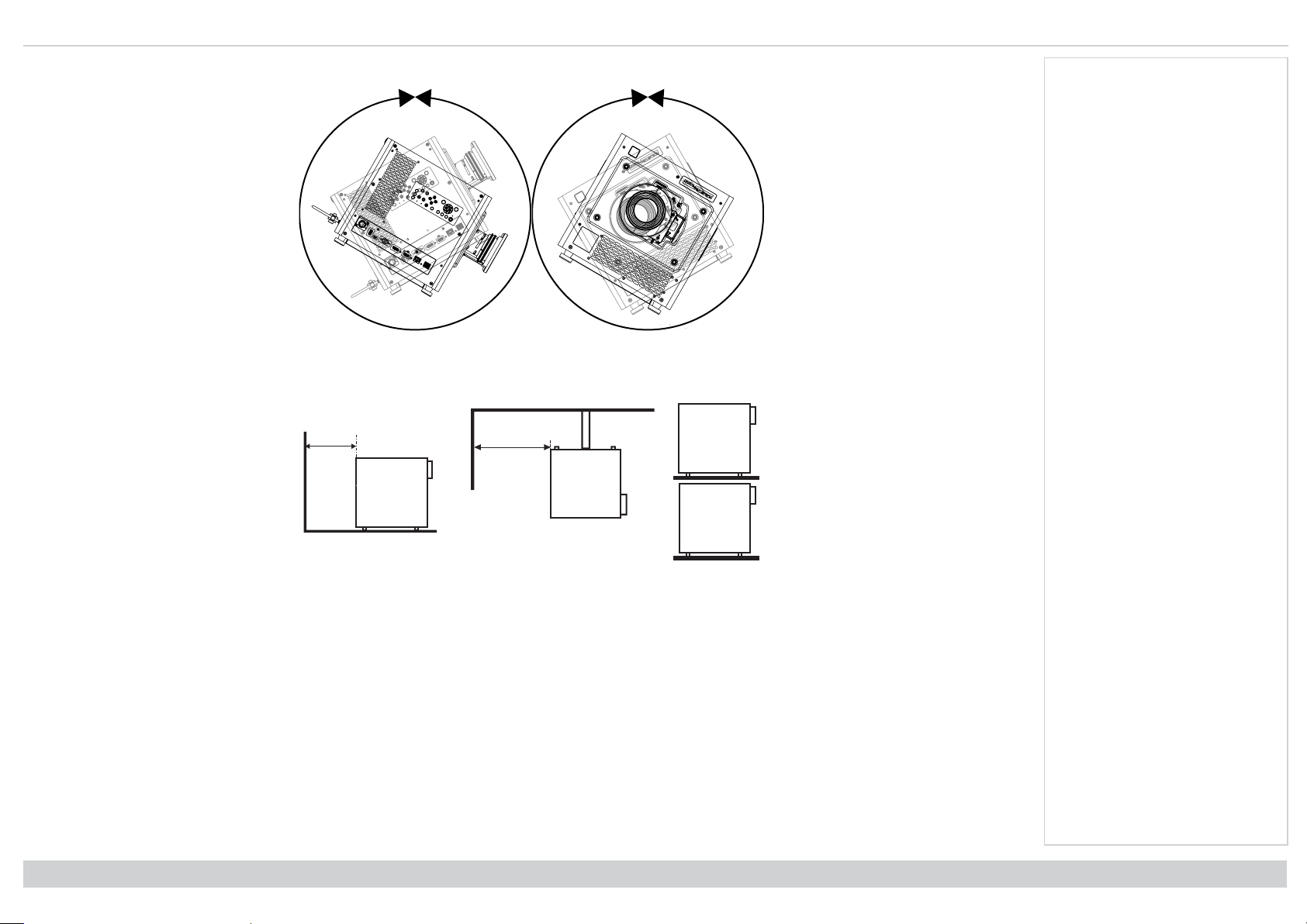
1. Install the screen, ensuring that it is in the best position for viewing by your audience.
2. Mount the Satellite Head, ensuring that it is at a suitable distance from the screen for the
image to fill the screen.
The drawing shows the positions of the mounting points:
l
Four adjustable feet for tabletop mount1.
Set the adjustable feet so that the Satellite Head is level, and perpendicular to the
screen.
Remove the feet and fit them to the top of the Satellite Head if you need to invert
the Satellite Head during tabletop use.
l
Four M4 holes for ceiling mount2.
The mounting screws should not penetrate more than 15 mm into the body of the
projector.
Notes
Always allow the Satelli te H ead
to cool for 5 minutes before
disconnecting the power or
moving the Satellite Head .
Ensure that there is at least 50
cm (19.7 in) o f space between
the ventil ation outlets and any
wall, and 30 cm (11.8 in) on all
other sides.
Do not use the threaded holes
for the adj ustable feet to hang
or mount the Satellite Head.
Avoid extending the adjustable
feet to the limit of the thread.
Installation & QuickStartGuide
Satellite Head Bottom
Rev A August2022
page 37
Page 38

DigitalProjection Ltd.Satellite HIGHlite4K-UHD Mounting the rackmountmodules
2
1
2
2
1
2
2
Mounting the rack mount modules
1. Fit any shelves or rails to the rack as required.
2. Fit any rails or mount supports to the Modular Light Source (MLS) or Satellite Control Module (SCM) as required.
3. Mount the module into the rack and secure in place with 4 standard rack locating bolts
The drawing shows the positions
of the fixing holes for the mount
supports and rack locating bolts
on the MLS.
1. Four standard rack
locating bolt holes1.
2.
Six M4 fixing holes2for
mounting rails or
supports. The screws
should not penetrate more
than 10 mm into the body
of the MLS.
The drawing shows the positions
of the fixing holes for the mount
supports and rack locating bolts
on the SCM.
Notes
1. Four standard rack
locating bolt holes1.
2.
Four M4 fixing holes
for mounting rails or
supports. The screws
should not penetrate more
than 10 mm into the body
of the SCM.
Rev A August2022
page 38
Installation & QuickStartGuide
Page 39

ConnectingtheSatellite LinkCable Digital Projection Ltd. Satellite HIGHlite4K-UHD
End-to-end SLC
1:2 SLC
1
2
Connecting the Satellite Link Cable
The Satellite Link Cable (SLC) must connect each Satellite Head to one or more Modular Light Sources (MLS). The type of SLC that is supplied depends on the
number and type of connections required for your system:
l 1:1. This system uses a single end-to end cable to connect a single MLS to a single
Satellite Head.
l 1:n. This system connects a single MLS to between two and four Satellite Head. A single
cable is supplied for this purpose. The cable includes a junction box with a single MLS
connector extending from one side and multiple Satellite Head connectors extending from
the other.
Notes
Handl e the SLC with care. Do
not drop or knock the SLC
when removed from its
packaging. Th e curvature of
the SLC shoul d never have a
radius of less than 20 cm.
Below this, the fiber inside the
cable may b e damaged.
The appropriate SLC cables are
supplied with the s ystem. Use only
the SLC c able provided.
It may be necess ary to clean the
SLC connectors before inst allation.
See Cleaning t he SLC on page149
The connectors at each end of the SLC are identified by polarity pins and holes:
l
A connector with a polarity hole1can only connect to a MLS.
l
A connector with a polarity pin2can only connect to a Satellite Head.
Installation & QuickStartGuide
Rev A August2022
page 39
Page 40

DigitalProjection Ltd.Satellite HIGHlite4K-UHD Connecting theSatellite LinkCable
1
2
1
2
To fit the SLC to the Satellite Head :
1. Remove the end cap from the SLC-Satellite Head connector.
2.
Slide the protective cover on the SLC socket on the Satellite Head open1.
3.
Align the polarity pin on the SLC2with the polarity hole on the SLC socket.
4. Insert the SLC.
5. Use the hex driver to screw in the fixing screw on the SLC and secure it in place.
Notes
To fit the SLC to the MLS:
1. Remove the end cap from the SLC-MLS connector.
2.
Slide the protective cover on the SLC socket on the MLS open1.
3.
Align the polarity hole on the SLC2with the polarity pin on the SLC socket.
4. Insert the SLC.
5. Use the hex driver to screw in the fixing screw on the SLC and secure it in place.
Rev A August2022
page 40
Installation & QuickStartGuide
Page 41

Connectingthe Signaland LAN cables DigitalProjection Ltd.Satellite HIGHlite4K-UHD
LAN Cable
LAN Cable
LAN Cable
LAN
Cable
Signal Cable
Connecting the Signal and LAN cables
Each Modular Light Source (MLS) must be connected to the Satellite Control Module (SCM) with a signal cable and a LAN cable. Each Satellite Head must be
connected to the SCM with a LAN cable.
l 1:1. One MLS and one Satellite Head are connected to the SCM.
l 1:n. Up to four Satellite Head and one MLS can be connected to the SCM.
Notes
The appropriate cables are supplied
with the Satellite MLS. A single
signal cable is suppliedfor each
MLS and a single LAN cable is
supplied for each MLS and Satellite
Head . Use only the c ables
provided.
Installation & QuickStartGuide
1:n System
Rev A August2022
page 41
Page 42

DigitalProjection Ltd.Satellite HIGHlite4K-UHD Connectingthe Signaland LAN cables
1
2
3
8910
11
12
456
7
A single LAN port1is located on the right side of the Satellite Head.
A single signal cable port2and a single LAN port3are located on the rear of the MLS.
Notes
There are four signal cable ports4-7and five LAN ports8-12located on the rear of the
SCM.
Rev A August2022
page 42
The appropriate cables are supplied
with the Satellite MLS. A single
signal cable is suppliedfor each
MLS and a single LAN cable is
supplied for each MLS and Satellite
Head . Use only the c ables
provided.
Installation & QuickStartGuide
Page 43

Connectingthe Signaland LAN cables DigitalProjection Ltd.Satellite HIGHlite4K-UHD
2
3
1
Single Satellite Head and Modular Light Source - 1:1 System
Make the following connections when connecting a system with a single Satellite Head and a
single Modular Light source:
1.
Connect a signal cable to the MLS and connect it to the MLS 1 socket1on the SCM.
2.
Connect a LAN cable to the MLS and connect it to the MLS 1 LAN socket3on the SCM.
3.
Connect a LAN cable to the Satellite Head and connect it to the Head 1 socket2on the
SCM.
Notes
Installation & QuickStartGuide
Example of a 1:1 system configuration
Rev A August2022
page 43
Page 44

DigitalProjection Ltd.Satellite HIGHlite4K-UHD Connectingthe Signaland LAN cables
234
5
6
1
3
4
Multiple Satellite Projector Heads - 1:n System
Make the following additional connections when connecting multiple Satellite Heads:
1.
Connect a signal cable to the MLS and connect it to the MLS 1 socket1on the SCM.
2.
Connect a LAN cable to the MLS and connect it to the MLS 1 LAN socket6on the SCM.
3.
Connect a LAN cable to the first Satellite Head and connect it to the Head 1 socket2on
the SCM.
4. Second Satellite Head:
l
Connect a LAN cable to the Satellite Head and connect it to the Head 2 LAN socket
on the SCM.
5. Third Satellite Head:
l
Connect a LAN cable to the Satellite Head and connect it to the Head 3 LAN socket
on the SCM.
6. Fourth Satellite Head:
l
Connect a LAN cable to the Satellite Head and connect it to the Head 4 LAN socket5on the SCM.
Notes
Rev A August2022
page 44
Installation & QuickStartGuide
Page 45

Connectingthe Signaland LAN cables DigitalProjection Ltd.Satellite HIGHlite4K-UHD
Notes
Installation & QuickStartGuide
Example of a 1:n system configuration
Rev A August2022
page 45
Page 46

DigitalProjection Ltd.Satellite HIGHlite4K-UHD Power Supply
Power Supply
AC Power Precautions
Warning! Death or Serious Injury could occur if the following precautions are ignored
Shock Hazard! Only use the AC power cord provided or recommended by the manufacturer
Fire & Shock Hazard! Do not operate the product unless the power cord, socket and plug meet local rating standards
Do not attempt operation if the AC supply is not within the specified parameters
The AC power cord must be inserted into a socket with grounding
Disconnect the product from the AC supply before installing, moving, servicing, cleaning or removing covers
Do not use an AC power cord that appears damaged
Do not overload power sockets or extension cords
Notes
Rev A August2022
page 46
Installation & QuickStartGuide
Page 47

Power Supply DigitalProjectionLtd.Satellite HIGHlite4K-UHD
1
1
Connecting the power supply
1.
Firmly push the mains connector into the AC In socket
When the cable is plugged in and the power supply is on, the module is OFF until the power
button is switched to ON.
When power is applied to the MLS the Laser illumination is not switched on.
Notes
Use only the p ower cable
provided.
Ensure that the power outlet
includes a gro und connection
as thi s equipment MUST be
earthed.
Handl e the power cable
carefully and avoid sharp
bends. Do not use a damaged
power cable.
Installation & QuickStartGuide
Satellite Head Rear
Rev A August2022
page 47
Page 48

DigitalProjection Ltd.Satellite HIGHlite4K-UHD Power Supply
1
1
MLS Rear
Notes
SCM Rear
Rev A August2022
page 48
Installation & QuickStartGuide
Page 49

Lasercolorcalibration DigitalProjection Ltd.Satellite HIGHlite4K-UHD
Laser color calibration
The laser colors must be calibrated after installation or after changing MLS within a system:
1. Press Menu on the remote control to display the OSD on the screen
2. Use the navigation buttons to highlight the Setup menu and press OK to access it
3. Navigate to the System Setting menu and press OK to access it
4. Navigate to the Laser Color CALfunction and press OK to recalibrate the colors.
The calibration will take approximately 30 to 40 minutes to complete.
System Setting
Orientation
High Altitude
Clock Adjust ►
Startup Logo
Blank Screen
PIC Mute ►
Smear Reduction
Output Frame Rate
HDMI Equalizer
Laser Color CAL
Back ►
Front Tabletop
Off
Original
Logo
Off
60Hz
Auto
OK
Notes
Installation & QuickStartGuide
Rev A August2022
page 49
Page 50

DigitalProjection Ltd.Satellite HIGHlite4K-UHD Operatingthe system
1078
13
12345
6
91112
Operating the system
The system has the following controls:
l Remote control
l Control panel on the Satellite Head
l Touchscreen control panel on the MLS
l Touchscreen control panel on the SCM
Satellite Head Control panel
1. ZOOM
Plus and minus buttons zoom in and out.
2. FOCUS
Plus and minus buttons move the focus in and out.
3. LENS SHIFT
Arrow buttons move the lens in the specified direction.
4. EXIT
Exits the current OSD page and enters the level
above.
5. Arrow buttons & ENTER
Press an arrow button to open the keystone menu.
Use the arrow buttons to adjust vertical and horizontal
keystone. After opening the OSD, use the arrow
buttons to highlight menu entries. Press ENTER to
open or execute the highlighted menu entry.
6. MENU
Displays and exits the OSD.
7. HOTKEYS
User selectable functions. Pre-set functions:
HOTKEY 1 Information
HOTKEY 2 Test Pattern
HOTKEY 3 Lens Load Memory
Additional options: Picture Mode, Ambient Brightness Correction, Freeze, PIP Swap.
8. PIC MUTE
9. CENTER LENS
Centers the lens.
10. ASPECT
Changes the aspect ratio.
11. AUTO SYNC
Re-synchronises with the current input signal.
Notes
See Connecting the power s upply
on page47.
The self-test is running when all the
LEDs on t he control panel are lit.
See Introduction to the OSD on
page72 for full details of how to use
the menu syst em.
See Introduction to the MLS
Touchscreen on page108 for full
details of how to use the MLS
touchscreen control panel.
See Introduction to the SCM
Touchscreen on page1 for full
details of how to use the SCM
touchscreen control panel.
Make sure the projector is fully
installed, all interlocks are in place
and the laser key switch on the
SCM and each MLS are enabled
before switching the projector on.
Control Panel
Rev A August2022
page 50
Installation & QuickStartGuide
Page 51

Operating the system DigitalProjection Ltd.Satellite HIGHlite 4K-UHD
12. INPUT
Switches to the next input source.
13. POWER
Switches the Laser on and off.
Notes
Installation & QuickStartGuide
Rev A August2022
page 51
Page 52

DigitalProjection Ltd.Satellite HIGHlite4K-UHD Operatingthe system
Pic Mute
OPEN
CLOSE
MENU
EXIT INFO
HDMI1
OK
OFF ON
ALT
LENS
FOCUS ZOOM
IN
OUT
IN
OUT
SHIFT
21 3
HDMI2 DVI
DisplayPort1
HD-T 3GSDI
VGA COMP1 COMP2
HDMI3
TEST
HDMI4
DisplayPort2
R G B ALL
3D EYE PIP SWAP
4 5 6
7 8 9 0
ALT
ADDR
OSD
OFF
ON
DEFAULT
FREEZE
RE-SYNC
A B C D
USER PRESET
7
6
543
218
Remote control
1. Power ON / OFF
Turns power on and off.
2. Pic Mute OPEN / CLOSE
l Press CLOSE to hide the projected image. When off, the laser remains on and a black
image is projected.
l Press OPEN to display the hidden image.
3. OSD ON / OFF
Enable and disable screen timeout messages and control whether to show the OSD
during projection.
4. MENU
Access the on screen display (OSD). If the OSD is open, press this button to go back to the
previous menu.
5. Navigation (arrows and OK)
6. EXIT
7. DEFAULT
8. INFO
OSD mode: Navigate through the menus with the arrows, confirm your choice with OK.
Lens adjustment modes: Press OK to switch between Shift Adjustment and Zoom /
Focus Adjustment. Use the arrows to shift, zoom or focus the lens. See 10 below.
Go up one level in the OSD. When the top level is reached, press to close the OSD.
When editing a parameter, press this button to restore the default value.
Access information about the projector.
Notes
Rev A August2022
page 52
Remote Control
Installation & QuickStartGuide
Page 53

Operating the system DigitalProjection Ltd.Satellite HIGHlite 4K-UHD
Pic Mute
OPEN
CLOSE
MENU
EXIT INFO
HDMI1
OK
OFF ON
ALT
LENS
FOCUS ZOOM
IN
OUT
IN
OUT
SHIFT
21 3
HDMI2 DVI
DisplayPort1
HD-T 3GSDI
VGA COMP1 COMP2
HDMI3
TEST
HDMI4
DisplayPort2
R G B ALL
3D EYE PIP SWAP
4 5 6
7 8 9 0
ALT
ADDR
OSD
OFF
ON
DEFAULT
FREEZE
RE-SYNC
A B C D
USER PRESET
12
9
10
11
13
14
15
16
9. FREEZE
Freeze the current frame.
10. LENS adjustment
l FOCUS IN / OUT: adjust focus.
l SHIFT: press and hold this button, then use the Navigation arrow buttons to move the
lens.
l ZOOM IN / OUT: adjust zoom.
11. USER PRESET A, B, C, D
Load user presets.
12. RE-SYNC
Re-synchronise with the current input signal
13. ALT
Press and hold this button to access alternative functions for other buttons on the remote.
14. DVI / DisplayPort2 / numeric input 3
15. HDMI 2 / HDMI 4 / numeric input 2
There is no DVI input on this projector.
There is no DisplayPort 2 input on this projector.
There is no HDMI 2 input on this projector.
There is no HDMI 4 input on this projector
16. HDMI 1 / HDMI 3 / numeric input 1
Select the HDMI 1 input.
There is no HDMI 3 input on this projector
Notes
This projector does not use the
following options on the remote:
HDMI 2
HDMI 3
HDMI 4
DisplayPort2
DVI
Installation & QuickStartGuide
Remote Control
Rev A August2022
page 53
Page 54

DigitalProjection Ltd.Satellite HIGHlite4K-UHD Operatingthe system
Pic Mute
OPEN
CLOSE
MENU
EXIT INFO
HDMI1
OK
OFF ON
ALT
LENS
FOCUS ZOOM
IN
OUT
IN
OUT
SHIFT
21 3
HDMI2 DVI
DisplayPort1
HD-T 3GSDI
VGA COMP1 COMP2
HDMI3
TEST
HDMI4
DisplayPort2
R G B ALL
3D EYE PIP SWAP
4 5 6
7 8 9 0
ALT
ADDR
OSD
OFF
ON
DEFAULT
FREEZE
RE-SYNC
A B C D
USER PRESET
19
17
18
20
17. DISPLAYPORT 1 / R / numeric input 4
Select DisplayPort 1 input.
18. HD-T / G / numeric input 5
Select the HDBaseT input.
19. ADDR / ALL (with red indicator at the top)
Assign and unassign an IR remote address.
To assign an IR remote address:
1. Press and hold this button until the red indicator starts flashing.
2. Release this button and while the red indicator is still flashing, enter a two-digit
address using the numeric input buttons. The indicator will flash three times quickly
to confirm the change.
To unassign an address and return to the default address 00:
1. Press and hold ALT and this button simultaneously until the red indicator flashes to
confirm the change.
20. 3GSDI / B / numeric input 6
There is no 3G-SDI input on this projector.
Notes
This projector does not use the
following options on the remote:
3GSDI
Rev A August2022
page 54
Remote Control
Installation & QuickStartGuide
Page 55

Operating the system DigitalProjection Ltd.Satellite HIGHlite 4K-UHD
Pic Mute
OPEN
CLOSE
MENU
EXIT INFO
HDMI1
OK
OFF ON
ALT
LENS
FOCUS ZOOM
IN
OUT
IN
OUT
SHIFT
21 3
HDMI2 DVI
DisplayPort1
HD-T 3GSDI
VGA COMP1 COMP2
HDMI3
TEST
HDMI4
DisplayPort2
R G B ALL
3D EYE PIP SWAP
4 5 6
7 8 9 0
ALT
ADDR
OSD
OFF
ON
DEFAULT
FREEZE
RE-SYNC
A B C D
USER PRESET
23
21
24
22
21. VGA / 3D / numeric input 7
There is no VGA input on this projector.
22. COMP1 / EYE / numeric input 8
There is no Component 1 input on this projector.
23. TEST / SWAP / numeric input 0
Show a test pattern. Press again to show the next test pattern: Off, Native White, Native
Black, Native Red, Native Green, Native Blue, Checkerboard, Crosshatch, ColorBar,
Aspect Ratio, Grayscale
The SWAP function is not used on this projector.
24. COMP2 / PIP / numeric input 9
There is no Component 2 input on this projector.
The PIP function is not used on this projector.
Notes
This projector does not use the
following options on the remote:
VGA
COMP 1
COMP 2
PIP
Installation & QuickStartGuide
Remote Control
Rev A August2022
page 55
Page 56

DigitalProjection Ltd.Satellite HIGHlite4K-UHD Operatingthe system
40˚
40˚
Infrared reception
The projector has infrared sensors at the front and rear.
The angle of acceptance is 40°. Make sure that the remote control is within the angle of
acceptance when trying to control the projector.
Notes
Rev A August2022
page 56
Installation & QuickStartGuide
Page 57

Operating the system DigitalProjection Ltd.Satellite HIGHlite 4K-UHD
12345
Module indicators
Satellite Head
1. TEMP INDICATOR
Off = no problem
Flashing red = temperature error
2. LIGHT INDICATOR
Off = light is switched off
On, amber = light is in forced ECO mode at high temperature
Flashing red (cycles of single flashes) = failure to light up during power up
Flashing red (cycles of double flashes) = unexpected light off while running
On, green = light is switched on
Flashing green (cycles of single flashes) = shutter is on and light source is temporarily off
3. PIC MUTE
Off = the projector is in standby
On, blue = the projector is on, normal projection
Flashing red = the projector is on, picture mute is activated
4. POWER
Off = the projector is switched off
Flashing amber = the projector is cooling down to standby mode
On, amber = the projector is in standby mode
Flashing green = the projector is warming up
On, green = the projector is switched on
5. STATUS
Off = no problem
Flashing amber (cycles of double flashes) = request to calibrate the lens
Flashing green (cycles of double flashes) = the projector is calibrating the lens
Flashing red (cycles of double flashes) = TEC or color sensor error
Flashing red (cycles of four flashes) = fan error
On, red = system error
Notes
Control Panel
Installation & QuickStartGuide
Rev A August2022
page 57
Page 58

DigitalProjection Ltd.Satellite HIGHlite4K-UHD Operatingthe system
1
1. LASER ON
Off = laser is off
On = laser is on
Notes
The Laser ON indicator will light up
for 30 seconds before the Laser
turns on t o warn that the laser is
about t o turn on.
Rev A August2022
page 58
Satellite Head Front
Installation & QuickStartGuide
Page 59

Operating the system DigitalProjection Ltd.Satellite HIGHlite 4K-UHD
1
1. STATUS
Off = no problem
Flashing amber = the projector is cooling down to standby mode
Flashing amber (cycles of double flashes) = request to calibrate the lens
On, amber = the projector is in standby mode
Flashing green = the projector is warming up
Flashing green (cycles of double flashes) = the projector is calibrating the lens
On, green = the projector is switched on
Flashing red (cycles of single flashes) = the lens or fiber link is open
Flashing red (cycles of double flashes) = TEC or color sensor error
Flashing red (cycles of four flashes) = fan error
On, red = system error
Notes
Installation & QuickStartGuide
Satellite Head Top
Rev A August2022
page 59
Page 60

DigitalProjection Ltd.Satellite HIGHlite4K-UHD Operatingthe system
1
2
3
1
Modular Light Source
1. LASER ON
Off = laser is off
On = laser is on
Satellite Control Module
1. LASER ON
Off = laser is off
On = laser is on
2. POWER GOOD
Green = 12V power is good
Amber = 12V good, but internal power rail has a fault
Red = 12V PSU not operating within specifications
3. INTERLOCK
On = Laser system is active and interlock complete
Off = Laser system is not active
Notes
The Laser ON indicator will light up
for 30 seconds before the Laser
turns on t o warn that the laser is
about t o turn on.
MLS Front
The Laser ON indicator will light up
for 30 seconds before the Laser
turns on t o warn that the laser is
about t o turn on.
SCM Front
Rev A August2022
page 60
Installation & QuickStartGuide
Page 61

Operating the system DigitalProjection Ltd.Satellite HIGHlite 4K-UHD
Switching the system on
1. Make sure a lens is fitted
2. Make sure the Signal, LAN and SLC cables are fitted
3. Make sure power cables are fitted to the Satellite Head, MLS and SCM
4. Make sure the power supply is on
5. Use the power switch located on the power cable socket to apply power to:
l The Satellite Head
l The MLS
l The SCM
6. Insert the laser on key into the laser on switch on the SCM and each MLS and turn to enable
7. Press ON on the Remote Control, or;
l Press Power on the Control Panel, or;
l Tick Enable in the Laser Power Page on the Satellite Control Module touch panel
Switching the projector off
1. Press OFF on the Remote Control, or;
l Press Power on the Control Panel, or;
l Deselect Enable in the Laser Power Page on the Satellite Control Module touch panel
2. Turn the laser on key on the SCM and each MLS to disable.
Emergency off
Notes
In an emergency, press the Emergency OFF button on the front of the Satellite Control Module to turn off the Laser Illumination
Installation & QuickStartGuide
Rev A August2022
page 61
Page 62

DigitalProjection Ltd.Satellite HIGHlite4K-UHD Operatingthe system
Interlock reset
In the event of the laser illumination turning off as a result of an Interlock break:
1. Make sure all interlocks are in place. See Interlock Switches on page21
2. Turn ON the laser illumination. See Switching the system on on the previous page
Selecting an input signal
1. Connect one or more image sources to the projector.
2. Select the input you want to display:
l Press one of the input buttons on the remote control.
l Alternatively, open the On-screen display (OSD) by pressing MENU. Highlight Input from the main menu, press ENTER/OK and then select an
input signal using the UP and DOWN arrow buttons. Press ENTER/OK to confirm your choice.
Selecting a test pattern
The following test patterns are available:Off, Native White, Native Black, Native Red, Native Green, Native Blue, Checkerboard, Crosshatch, ColorBar, Aspect
Ratio, Grayscale
Use one of the following methods to display a test pattern:
l Press TEST on the remote control.
Use the LEFT and RIGHT arrow buttons to cycle through the test patterns.
l Press MENU open the OSD. Highlight Test Patterns from the main menu, then select a test pattern using the LEFT and RIGHT arrow buttons.
After the final test pattern, the projector exits test pattern mode and returns to the main image. To view test patterns again, you need to press TEST again. If you
wish to exit the test patterns before you reach the final one, press TEST or EXIT at any time.
Notes
Please refer to the connection
guide for details about connecting a
signal source. See Signal inputs on
page66
Rev A August2022
page 62
Installation & QuickStartGuide
Page 63

Operating the system DigitalProjection Ltd.Satellite HIGHlite 4K-UHD
Adjusting the lens
You can use the following options to adjust the lens:
l Remote control. See Remote control on page52
l On screen display (OSD).
Adjusting the image
Orientation
This can be set from the Setup menu. See on page1 for guidance.
Highlight Orientation and choose from Front Tabletop, Front Ceiling, Rear Tabletop, Rear Ceiling and Auto-front.
Picture
Settings such as Gamma, Brightness, Contrast, Saturation, Hue and Sharpness can be set from the Image menu. See on page1 for guidance.
Notes
Installation & QuickStartGuide
Rev A August2022
page 63
Page 64

DigitalProjection Ltd.Satellite HIGHlite4K-UHD
This page is intentionally left blank
Rev A August2022
Page 65

Satellite HIGHlite 4K-UHD
Digital Video Projector
CONNECTION GUIDE
Rev A August2022
122-933A
Page 66

DigitalProjection Ltd.Satellite HIGHlite4K-UHD Signal inputs
12345
Signal inputs
Digital inputs and outputs
1. USB
USB 5V / 2A output. Connect a USB cable to supply
power to an external device.
2. DisplayPort
DisplayPort 1.2 input. Connect a DisplayPort cable to
the connector. Supports sources up to 4K resolution
at 60 Hz and 2048 x 1080 at 120Hz.
3. HDMI
HDMI 2.0 inputs supporting HDCP 2.2. Connect an
HDMI cable to the connector.
4. HDBaseT/LAN
Receives digital signal from HDBaseT-compliant
devices. Connect an HDBaseT cable.
5. Ethernet
Provides LAN connectivity via an ethernet cable.
Notes
For simultaneous HDBaseT and
LAN connectivity, a third-party
distribution product c an be utilised
to combine HDBaseT video stream
with LAN connection for delivery t o
the projector.
See 2D formats on page144 for
information about supported 2D
signal input modes.
Satellite Head Connection Panel
Rev A August2022
page 66
Connection Guide
Page 67

Signal inputs Digital Projection Ltd.Satellite HIGHlite 4K-UHD
EDID
EDID
EDID
EDID
123
EDID on the DisplayPort, HDMI, and HDBaseT inputs
If you are using a computer graphics card or another source that obeys the EDID protocol, the source will automatically configure itself to suit the capability of the
projector.
Otherwise refer to the documentation supplied with the source to manually set the resolution to the DMD™ resolution of the projector or the nearest suitable
setting. Switch off the source, connect to the projector, then switch the source back on again.
Using DisplayPort / HDMI / HDBaseT switchers with the projector
When using a DisplayPort/HDMI/HDBaseT source switcher with the projector, it is important to set the switcher so that it passes the projector EDID through to the
source devices.
If this is not done, the projector may not be able to lock to the source or display the source correctly as its video output timings may not be compatible with those of
the projector. Sometimes this is called transparent, pass-through or clone mode. See your switcher’s manual for information on how to set this mode.
1. Sources
2. Switcher
3. Satellite Head
Notes
Connection Guide
The EDIDs in the switcher should be the same as the one in the projector.
Rev A August2022
page 67
Page 68

DigitalProjection Ltd.Satellite HIGHlite4K-UHD Controlconnections
2
3
1
4
ETHERNET
ART-NET
Control connections
1. Ethernet
This system is linked via a series of Ethernet
connections. See Connecting the Signal and LAN
cables on page41
2. Service
This port is for servicing purposes only.
3. RS232
This port is for servicing purposes only.
4. Ethernet
This system can be controlled via an Ethernet
connection. Use an Ethernet cable to connect the
SCM to your computer.
Satellite Head Connection Panel
Notes
See "Connecting the Signal and
LAN cables" on page41 and
"Connecting the Satellite Link
Cable" on page39 for guidance on
setting up the connections between
each Satellite Head, MLS and
SCM.
For a list of all commands used to
control the project or via LAN, see
the Protocol Guide (available
separately).
Only one control connection should
be used at any one t ime.
With an Ethernet connection t he
system can serve a web page
offering status and controls. See
Served web pages on page153 for
guidance on accessing and using
the served web pages.
Projector Con trol ler is available
for download, free of c harge, from
the Digital Projection website.
Rev A August2022
page 68
SCM Connection Panel
Connection Guide
Page 69

Controlconnections Digital Projection Ltd. Satellite HIGHlite4K-UHD
Un-crossed
LAN cable
LAN connection examples
The projector’s features can be controlled via a LAN connection, using Digital Projection’s Projector Controller application or a terminal emulation program.
Notes
With an Ethernet connection t he
system can serve a web page
offering status and controls. See
Served web pages on page153 for
guidance on accessing and using
the served web pages.
Projector Con trol ler is available
for download, free of c harge, from
the Digital Projection website.
For simultaneous HDBaseT and
LAN connectivity, a third-party
distribution product c an be utilised
to combine HDBaseT video stream
with LAN connection for delivery t o
the projector.
Connection Guide
Rev A August2022
page 69
Page 70

DigitalProjection Ltd.Satellite HIGHlite4K-UHD
This page is intentionally left blank
Rev A August2022
Page 71

Satellite HIGHlite 4K-UHD
Digital Video Projector
ON SCREEN DISPLAY (OSD) OPERATING GUIDE
Rev A August2022
122-933A
Page 72

DigitalProjection Ltd.Satellite HIGHlite4K-UHD Introductiontothe OSD
Pic Mute
OPEN
CLOSE
MENU
EXIT INFO
HDMI1
OK
OFF ON
ALT
LENS
FOCUS ZOOM
IN
OUT
IN
OUT
SHIFT
21 3
HDMI2 DVI
DisplayPort1
HD-T 3GSDI
VGA COMP1 COMP2
HDMI3
TEST
HDMI4
DisplayPort2
R G B ALL
3D EYE PIP SWAP
4 5 6
7 8 9 0
ALT
ADDR
OSD
OFF
ON
DEFAULT
FREEZE
RE-SYNC
A B C D
USER PRESET
EXIT MENU
STATUS
LENS
SHIFT
ZOOM
FOCUS
POWER
INPUT
PIC MUTE
CENTER
LENS
LIGHTTEMP
AUTO
SYNC
ASPECT
HOTKEYS
3
2
1
Introduction to the OSD
This section describes the operation of the OSD.
Opening the Menu
Use the projector control panel or
the remote control to open the onscreen display (OSD). On either
device:
1. Press the MENU button.
The OSD opens showing
the list of available menus
Notes
Projector control panel
Opening a submenu
1. Move up and down the list using the UP and DOWN arrow buttons.
2. Press ENTER on the control panel or OK on the remote control to open a submenu.
This guide refers to the above two buttons as ENTER/OK.
Rev A August2022
page 72
Remote control
On Screen Display(OSD)Operating Guide
Page 73

Introduction totheOSD Digital Projection Ltd. Satellite HIGHlite 4K-UHD
Exiting menus and closing the OSD
To go back to the previous page:
1. Press EXIT.
To close the OSD:
1. Press MENU.
Or:
1. Go back to the top level menu
2. Press EXIT.
Inside a menu
When you open a menu, the page consists of the following elements:
l Title bar at the top shows which menu you have accessed.
l Highlighted item
l Available and unavailable items Unavailable items appear a pale gray color. Whether an item is
available may depend on other settings.
l The text or symbol to the right of an item shows whether the item:
l has a value that can be changed (the current value is shown)
l opens a sub-menu (an arrow button is displayed)
l executes a command (the space to the right of the item is blank).
Main Menu
Input ►
Lens ►
Image ►
Color ►
Geometry ►
Setup ►
Network ►
Information ►
On Screen Display (OSD): Top Level Menu
Menu Name
Highlighted Item Value
Menu Item Value
Unavailable Item Value
Slider Value
Sub-menu ►
Command
Notes
The highlighted item has blue
background.
On Screen Display(OSD)Operating Guide
Inside a menu
Rev A August2022
page 73
Page 74

DigitalProjection Ltd.Satellite HIGHlite4K-UHD Introductiontothe OSD
Accessing sub menus
Use the UP and DOWN arrow buttons to highlight the sub-menu, then press ENTER/OK.
Executing commands
Some items contain a command, such as an OK button.
Press ENTER/OK to execute the highlighted command.
You may be asked for confirmation. Use the ENTER/OK to confirm, or EXIT to cancel.
Menu Name
Menu Item Value
Item With Command
Command
Notes
OK
Rev A August2022
page 74
On Screen Display(OSD)Operating Guide
Page 75

Introduction totheOSD Digital Projection Ltd. Satellite HIGHlite 4K-UHD
Editing projector settings
If the highlighted menu item contains a list of values to choose from, you can change the value by doing
the following:
1. Highlight the menu item and press ENTER/OK.
2. In the list of values that opens, use the UP and DOWN arrow buttons to highlight a value, then
press ENTER/OK again to select the highlighted value.
Using a slider to set a value
Some parameters show a slider. To set such a parameter:
1. Press the LEFT or RIGHT arrow button, or ENTER/OK. The arrow buttons will open the slider and
adjust the value at the same time. ENTER/OK will open the slider without altering the initial value.
2. Use the LEFT and RIGHT arrow buttons to move the slider.
3. When ready, press RETURN to exit the slider and return to the menu.
Menu Name
Highlighted Item Current Value
Menu Item
Menu Item
Highlighted
Value
Value
Value
Value
List of Values
Menu Name
Menu Item Value
Item With Slider Value
Notes
Some menu items may be
unavailable due to s ettings in other
menus. Unavailable menu items
appear gray
Please wait f or any value changes
to be applied
On Screen Display(OSD)Operating Guide
Slider
Rev A August2022
page 75
Page 76

DigitalProjection Ltd.Satellite HIGHlite4K-UHD Introductiontothe OSD
Editing numeric values
Some parameters take numeric values without using sliders - for example, color matching values or IP
addresses.
1. Use the UP and DOWN arrow buttons to highlight the row containing the numeric field you wish to
edit.
2. Press ENTER/OK to enter edit mode. A numeric field in edit mode is white text on blue
background.
3. In edit mode:
l Use the UP arrow button to increase the numeric value.
l Use the DOWN arrow button to decrease the numeric value.
4. Use the LEFT and RIGHT arrow buttons to edit the next or previous numeric fields within the same
row.
5. Once ready, press ENTER/OK to exit edit mode.
Notes
Data
Row x: 0.658 y: 0.339
Highlighted Row x: 0.315 y: 0.662
Row x: 0.146 y: 0.043
Row x: 0.276 y: 0.283
Rev A August2022
page 76
On Screen Display(OSD)Operating Guide
Page 77

Usingthe projector DigitalProjection Ltd. Satellite HIGHlite 4K-UHD
Using the projector
Main Menu
l Input, Lens, Image, Color, Geometry, Setup, Network, Information.
Press ENTER/OK to open these menus and access various settings.
Input
l Input
Press ENTER/OK to open the list of available inputs. Use the UP and DOWN arrow buttons to
select an input from the list, then press ENTER/OK to confirm your choice. Press EXIT to return to
the main menu.
l Test Pattern
Off, Native White, Native Black, Native Red, Native Green, Native Blue, Checkerboard,
CrossHatch, ColorBar, Aspect Ratio, Greyscale.
Use the LEFT and RIGHT arrow buttons to switch between values.
l Resync
Press ENTER/OK to force the projector to resynchronize with the current input
l Auto Source
If this setting is On, the projector will automatically search for an active input source.
l EDID Mode.
Press ENTER/OK to open this sub menu.
l Main Menu
Go back to the main menu.
Main Menu
Input ►
Lens ►
Image ►
Color ►
Geometry ►
Setup ►
Network ►
Information ►
Input
Input
Resync
Test Pattern
Auto Source
EDID Mode ►
Main Menu ►
HDBaseT
OK
Off
Notes
See Signal inputs on page66 f or
information about the available
inputs and connections.
Selecting a test pattern hides the
OSD. Press EXIT to hide the t est
pattern, and t hen press M ENU to
show the OSD
On Screen Display(OSD)Operating Guide
Rev A August2022
page 77
Page 78

DigitalProjection Ltd.Satellite HIGHlite4K-UHD Usingthe projector
EDID Mode
Each signal input type is available in the menu. Select the appropriate frame rate and display resolution
for each input.
EDID Mode
HDMI
HDBaseT
DisplayPort
Back ►
4K/60 HDR
4K/30
4K/60 HDR
Notes
Rev A August2022
page 78
On Screen Display(OSD)Operating Guide
Page 79

Usingthe projector DigitalProjection Ltd. Satellite HIGHlite 4K-UHD
Lens
l Lens Lock
When this feature is On, all other Lens menu items are disabled.
l Center Lens
Centers the lens.
l Lens Memory
Opens a sub-menu, see next page.
l Main Menu
Go back to the main menu.
Lens Memory
This menu allows you to load, save and delete up to ten lens presets, containing position, zoom, focus
and shift adjustment information.
For example, if using different screen sizes and aspect ratios, you can save zoom, focus and positioning
for each screen size and aspect ratio in a dedicated preset.
Use Clear Memory to delete a memory preset if you need to save a new combination of lens settings in
its place. Overwriting a saved memory preset is not possible.
Lens
Lens Lock
Center Lens
OK
Lens Memory ►
Main Menu ►
Lens Memory
Load Memory ►
Save Memory ►
Clear Memory ►
Back ►
Notes
On Screen Display(OSD)Operating Guide
Rev A August2022
page 79
Page 80

DigitalProjection Ltd.Satellite HIGHlite4K-UHD Usingthe projector
Lens Load Memory
Memory 1
Memory 2
Memory 3
Memory 4
Memory 5
Memory 6
Memory 7
Memory 8
Memory 9
Memory 10
Back ►
OK
OK
OK
OK
OK
OK
OK
OK
OK
OK
Lens Save Memory
Memory 1
Memory 2
Memory 3
Memory 4
Memory 5
Memory 6
Memory 7
Memory 8
Memory 9
Memory 10
Back ►
OK
OK
OK
OK
OK
OK
OK
OK
OK
OK
Lens Clear Memory
Memory 1
Memory 2
Memory 3
Memory 4
Memory 5
Memory 6
Memory 7
Memory 8
Memory 9
Memory 10
Back ►
OK
OK
OK
OK
OK
OK
OK
OK
OK
OK
Notes
Rev A August2022
page 80
On Screen Display(OSD)Operating Guide
Page 81

Usingthe projector DigitalProjection Ltd. Satellite HIGHlite 4K-UHD
Image
l Smooth Picture
When this feature is On, the projector will resize the incoming signal to display in 4K-UHD
resolution.
When Off sources will be displayed within native 4K resolution.
Aspect ratio selection applies for both Smooth Picture On or Off.
l Gamma
Choose a de-gamma curve from 1.0, 1.8, 2.0, 2.2, 2.35, 2.5, DICOM
Used correctly, the Gamma setting can improve contrast while maintaining good details for blacks
and whites.
If excess ambient light washes out the image and it is difficult to see details in dark areas, lower
the Gamma setting to compensate. This improves contrast while maintaining good details for
blacks. Conversely, if the image is washed out and unnatural, with excessive detail in black areas,
increase the setting.
DICOM is a simulated DICOM display, which can be used for training applications.
l HDR
Choose from Off, Auto, PQ-400, PQ500, PQ1000 and HLG.
HDR (High Dynamic Range) is a form of gamma developed to create more realistic experience
when viewing images delivered using this format, such as scenes with bright sunlight. Unlike
traditional gamma, HDR is not device or installation independent. HDR content will come with a
recommended brightness regardless of screen size.
For best results, as a guideline, the following screens sizes are suggested.
HDRScreen sizes Screen width (cm)
Model Lumens 300 NIT 400 NIT 500 NIT 600 NIT 1000 NIT 4000 NIT
HIGHLite Satellite 4K-UHD 9,000 411 356 319 291 226 113
HDR options should only be used with media players and sources equipped with HDR capability and outputting HDR content.
Perceptual Quantizer (PQ) is the digitizing concept for capture and display and provides metadata to enable the display to understand the coding of the
content.
The NIT numbers relate to the brightness of the viewing conditions in NIT. NIT is the unit of brightness measurement for monitors and LED walls that emit
light rather than reflect it such as a projection screen. However it is a reference to the brightness you would choose for a given environment.
HLG is High Dynamic Range – hybrid-log-gamma. This is a broadcast version of HDR for live TV and events.
l Ambient Brightness Correction
Choose from; Off, BC1, BC2, BC3, BC4, BC5, BC6
This adjusts brightness, contrast, saturation, hue and sharpness settings to levels that are pre-configured for different levels of ambient light.
l Brightness, Contrast, Saturation, Hue, Sharpness
Highlight the setting you wish to edit, and then press ENTER/OK, or the LEFT or RIGHT arrow button to open the slider.
Use the LEFT and RIGHT arrow buttons to adjust the slider.
Press EXIT to close the slider and return to the menu, or MENU to close the slider and return to the projected image.
l Noise Reduction
Choose a level of noise reduction from Off, Low, Middle and High.
Image
Smooth Picture
Gamma
HDR
Ambient Brightness
Correction
Brightness 100
Contrast 100
Saturation 100
Hue 100
Sharpness 0
Noise Reduction
Advanced ►
Main Menu ►
Off
2.2
Off
Off
Off
Notes
This product includes a DICOM
simulation feature intendedfor
training and other non-medical
diagnosis purposes.
Selecting a HDR sett ing w ill disable
the Gamma s etting.
If t he HDR setting is Auto, the
Gamma setting is only disabled
when t he image source is HDR
The HDR AUTO setting is only
available when the incoming signal
is HDR c apable
On Screen Display(OSD)Operating Guide
Rev A August2022
page 81
Page 82

DigitalProjection Ltd.Satellite HIGHlite4K-UHD Usingthe projector
l Advanced
Opens a sub-menu.
l Main Menu
Go back to the main menu.
Advanced
l Freeze
Freezes the current frame.
l Ambient Brightness Correction
Choose from; Off, BC1, BC2, BC3, BC4, BC5, BC6
This adjusts brightness, contrast, saturation, hue and sharpness settings to levels that are preconfigured for different levels of ambient light.
l Dynamic Contrast
Tick to activate. Will automatically adjust the contrast level according the displayed image.
l Light Off Timer
When Dynamic Contrast is On, the Light Off Timer will define if laser light source will turn off
after a period of time has passed. The options are: 0.5, 1.0, 1.5, 2.0, 3.0, 4.0 seconds.
l Main Menu
Go back to the main menu.
Advanced
Freeze
Ambient Brightness
Correction
Dynamic Contrast
Light Off Timer
Back ►
Off
0.5s
Notes
Rev A August2022
page 82
On Screen Display(OSD)Operating Guide
Page 83

Usingthe projector DigitalProjection Ltd. Satellite HIGHlite 4K-UHD
Color
Color Space
In most cases, the Auto setting determines the correct colorspace to use. If it does not, you can choose a
specific colorspace:
Choose from Auto, YPbPr, YCbCr, RGB PC and RGB Video.
Color
Color Space
Color Mode
ColorMax
Manual Color Matching ►
Color Temperature
Gains and Lifts ►
Main Menu ►
Auto
Color Max
Peak
6500K
Color
Color Space Auto
Color Mode
ColorMax
Manual Color Matching
Color Temperature
Gains and Lifts
Main Menu ►
Auto
YPbPr
YCbCr
RGB PC
RGB Video
Notes
On Screen Display(OSD)Operating Guide
Rev A August2022
page 83
Page 84

DigitalProjection Ltd.Satellite HIGHlite4K-UHD Usingthe projector
Color Mode
The projector can work in the following color modes:
l ColorMax
l Manual Color Matching
l Color Temperature
l Gains and Lifts
ColorMax
1. Set Color Mode to ColorMax.
2. Navigate to the ColorMax setting.
3. Choose from REC709, Extended, Ultra, Peak, User 1 and User 2. User 1 and User 2 are userdefined color gamuts set via the Setup > ColorMax menu.
Color
Color Space Auto
Color Mode ColorMax
ColorMax
Manual Color Matching
Color Temperature
Gains and Lifts
Main Menu
ColorMax
ManualColor
Matching
Color Temperature
Gains and Lifts
Color
Color Space Auto
Color Mode ColorMax
ColorMax Peak
Manual Color Matching
Color Temperature
Gains and Lifts
Main Menu
REC709
Extended
Ultra
Peak
User 1
User 2
Notes
Only one color mode can be
selected at a time. Sett ings used
by the other c olor modes are
disabled.
See Setup menu on page1 for
further information about setting up
the User 1 and User 2color
gamuts.
Rev A August2022
page 84
On Screen Display(OSD)Operating Guide
Page 85

Usingthe projector DigitalProjection Ltd. Satellite HIGHlite 4K-UHD
Manual Color Matching
1. Set Color Mode to Manual Color Matching.
2. Open the Manual Color Matching submenu.
Here you can do the following:
l Adjust Hue, Saturation and Gain settings for each individual color to improve the color balance of
the projected image.
l Adjust white balance RGB values.
l Reset all values.
Manual Color Matching - Red
Hue 500
Saturation 500
Gain 500
Manual Color Matching
Red ►
Green ►
Blue ►
Yellow ►
Cyan ►
Magenta ►
White Balance ►
Reset
Back ►
Manual Color Matching - White
Balance
Red 500
Green 500
Blue 500
Notes
See Color matching parameters
explainedon t he next page for more
details about the H ue, Saturation
and Gain s ettings.
On Screen Display(OSD)Operating Guide
Rev A August2022
page 85
Page 86

DigitalProjection Ltd.Satellite HIGHlite4K-UHD Usingthe projector
Color matching parameters explained
The levels of hue, saturation and gain in the Manual Color
Matching menu change the color values in the following
ways:
1. Hue Specifies the position of each color (red, yellow,
green, cyan, blue and magenta) relative to its
neighboring colors.
2. Saturation Specifies the level of white in each color
(i.e. how “pale” each color is).
3. Gain Controls the amount of light that goes into each
color, i.e. the lowest gain would produce black.
Notes
Rev A August2022
page 86
On Screen Display(OSD)Operating Guide
Page 87

Usingthe projector DigitalProjection Ltd. Satellite HIGHlite 4K-UHD
Color Temperature
1. Set Color Mode to Color Temperature.
2. Navigate to the Color Temperature setting. Choose a value from 3200K (warmer) to 9300K
(cooler) or Native (no correction).
Gains and Lifts
1. Set Color Mode to Gains and Lifts.
2. Open the Gains and Lifts submenu.
Lifts allow you to adjust black levels of individual colors, while gains adjust the bright part of the scale.
Set the sliders as required
Color
Color Space Auto
Color Mode Color Temperature
ColorMax Peak
Manual Color Matching ►
Color Temperature Native
Gains and Lifts
Main Menu
3200K
5400K
6500K
7500K
9300K
Native
Gains and Lifts
Red Lift 100
Green Lift 100
Blue Lift 100
Red Gain 100
Green Gain 100
Blue Gain 100
Reset
Back ►
OK
Notes
On Screen Display(OSD)Operating Guide
Rev A August2022
page 87
Page 88

DigitalProjection Ltd.Satellite HIGHlite4K-UHD Usingthe projector
Geometry
This menu allows you to compensate for image distortions caused by an unusual projection angle or
irregular screen surface.
Aspect Ratio
Digital Zoom ►
Overscan
Blanking ►
Main Menu ►
Aspect Ratio
This feature defines the aspect ratio of the source. Use the Setup > Screen Setting to define the screen aspect ratio.
If you choose a preset aspect ratio from here, it will give you the best fit for your selection.
Choose from:
l 5:4
l 4:3
l 16:10
l 16:9
l 1.88
l 2.35
l TheaterScope
l Source
l Unscaled
Notes
Geometry
4:3
Off
Image scaling and aspect ratio are
also influenced by Setup > Screen
Setting.
See Theaterscope setting on t he
facing page for further information
about t he TheaterScope aspect
ratio.
Rev A August2022
page 88
On Screen Display(OSD)Operating Guide
Page 89

Usingthe projector DigitalProjection Ltd. Satellite HIGHlite 4K-UHD
Black margin – part of the source
Black margin – part of the source
Theaterscope setting
The TheaterScope setting is used in combination with an anamorphic lens to restore 2.35: images packed into a 16:9 frame. Such images are projected with
black lines at the top and bottom of the 16:9 screen to make up for the difference in aspect ratios.
Without an anamorphic lens and without the TheaterScope setting applied, a 16:9 source containing a 2.35:1 image looks like this:
If we change the setting to TheaterScope, the black lines will disappear but the image will stretch vertically to reach the top and bottom of the DMD™:
An anamorphic lens will stretch the image horizontally, restoring the original 2.35 ratio:
Notes
TheaterScope is used with an
anamorphic lens.
If you use TheaterScope, set your
screen aspect ratio to 16:9.
On Screen Display(OSD)Operating Guide
Rev A August2022
page 89
Page 90

DigitalProjection Ltd.Satellite HIGHlite4K-UHD Usingthe projector
Digital Zoom
Digital zooming enlarges a section of the image, while the area outside the enlarged section is cropped
out to preserve the overall image size.
l Digital Zoom defines the level of zoom that needs to be applied. If Digital Zoom is set to 0, then
the other settings in the menu will be disabled.
l Digital Pan and Digital Scan specify the area that is being enlarged:
l Digital Pan adjusts the horizontal coordinates.
l Digital Scan adjusts the vertical coordinates.
The Reset command restores the default Digital Zoom, Digital Pan and Digital Scan values.
Digital Zoom
Digital Zoom 0
Digital Pan 0
Digital Scan 0
Reset
Back ►
OK
Notes
Digital Zoom is a temporary setting
and not retained after an input
change or power cycle.
Rev A August2022
page 90
On Screen Display(OSD)Operating Guide
Page 91

Usingthe projector DigitalProjection Ltd. Satellite HIGHlite 4K-UHD
Overscan
Use this setting to compensate for noisy or badly defined image edges.
Crop removes unwanted artifacts from the edges of your image by cropping the edges.
Zoom increases the size of the image to force the edges off-screen
Geometry
Aspect Ratio
Digital Zoom ►
Overscan
Blanking ►
Main Menu ►
5:4
Off
Notes
On Screen Display(OSD)Operating Guide
Rev A August2022
page 91
Page 92

DigitalProjection Ltd.Satellite HIGHlite4K-UHD Usingthe projector
Blanking
Use this feature to:
l fit an odd-sized screen;
l cut off timecode dots in the top line of a picture;
l cut off subtitles, etc.
Select the edge you wish to blank and use the LEFT and RIGHT arrow buttons to determine the amount
of correction.
Use the Reset command to restore blanked edges.
Blanking
Top 0
Bottom 0
Left 0
Right 0
Reset
Back ►
OK
Notes
Rev A August2022
page 92
On Screen Display(OSD)Operating Guide
Page 93

Usingthe projector DigitalProjection Ltd. Satellite HIGHlite 4K-UHD
Setup
Notes
Setup
System Setting ►
Screen Setting ►
Power Setting ►
ColorMax Setting ►
Control Setting ►
OSD Settings ►
Main Menu ►
On Screen Display(OSD)Operating Guide
Rev A August2022
page 93
Page 94

DigitalProjection Ltd.Satellite HIGHlite4K-UHD Usingthe projector
System Setting
l Orientation
Choose from Front Tabletop, Front Ceiling, Rear Tabletop, Rear Ceiling and Auto-front.
l High Altitude
Choose from Off, On and Auto.
l Clock Adjust
Access the submenu to set current date and local time.
l Startup Logo
Choose from Off, Original and User.
Select original to display the Digital Projection Ltd. logo on startup. Select User to display a
custom logo. Use the custom logo upload tool to set the custom logo for the User option.
l Blank Screen
Choose from Logo, Black, Blue and White.
l PIC Mute
Access sub menu to set up the picture mute control.
l Smear Reduction
Choose from Off, 6ms, 7ms, 8ms, 9ms, and 10ms. When projecting footage with a high frame
rate, fast moving images may appear as a smear across the display. Select a smear reduction
value to reduce this effect.
l Output Frame Rate
Choose from Auto, 48Hz, 50Hz and 60Hz. Select Auto to use the same frame rate as the input
signal. When switching between inputs on auto output frame rate, the projector measures the input frame rate before setting the output frame rate. When
you know that all input frame rates are the same value, you can set an output frame rate to reduce the time it takes to switch between inputs.
l HDMI Equalizer
Choose from Auto, High, Middle and Low. When transmitting signals via a HDMI cable, signal noise can disrupt the information received by the projector.
High bandwidth signals, poor quality HDMI cables and longer HDMI cables can increase the signal noise. Use the HDMI Equaliser to improve HDMI
signal acquisition.
l Laser Color CAL
Select OK to recalibrate the colors.
l Back
Go back to the previous menu.
System Setting
Orientation
High Altitude
Clock Adjust ►
Startup Logo
Blank Screen
PIC Mute ►
Smear Reduction
Output Frame Rate
HDMI Equalizer
Laser Color CAL
Back ►
Front Tabletop
Off
Original
Logo
Off
60Hz
Auto
OK
Notes
Smear reductio n reduces the
brightness of the displayed image
When using the Laser Color CAL,
the command must be sent from
head 1 in t he syst em. Use the color
max function t o adjust the color
settings of any additional heads.
Rev A August2022
page 94
On Screen Display(OSD)Operating Guide
Page 95

Usingthe projector DigitalProjection Ltd. Satellite HIGHlite 4K-UHD
Clock Adjust
Use this menu to set date (in dd:MM:yyyy format), time (in HH:mm format) and time zone.
The date and time set here will affect any schedule created within the Power On/Off menu.
PIC Mute
PIC mute allows the projected image to be hidden without turning the projector off.
l PIC Mute
Choose from Laser and DMD Blanking. Select PIC Mute to turn the laser off when the PIC Mute
activated. Select DMD Blanking to project a black image when PIC Mute is activated.
Clock Adjust
Date (dd:MM:yyyy) 30:11:2017
Time (HH:mm) 16:00
Time Zone 0
Back ►
PIC Mute
PIC Mute
Back ►
Laser
Notes
On Screen Display(OSD)Operating Guide
Rev A August2022
page 95
Page 96

DigitalProjection Ltd.Satellite HIGHlite4K-UHD Usingthe projector
Screen Setting
l Screen Format
Choose from 16:10, 16:9, 4:3 and 2.35:1.
l Screen Position
Use the slider to adjust the position of the image within the unused space of the projectors
display.
l Back
Go back to the previous menu.
Power Setting
l Auto Power On
Set this to On if you want the projector to start up immediately when the mains is connected. Set
this to Off if you want the projector to go into STANDBY mode when the mains is connected. In
this case, the projector will not start up until the POWER button is pressed on the control panel or
the ON button is pressed on the remote control.
l Auto Power Off
Choose from Off, 5 min, 10 min, 15 min, 20 min. Use this setting to activate STANDBY mode
when no input source is detected after a period of time.
l Schedule Management
Access sub menu to set up a power on-off schedule.
l Instant Startup
When ON only the Laser will be turned off when the Power off command is given. A subsequent
Power On will turn on the laser giving an apparent very fast power on.
l Standby Period
Used with Instant Startup. If Instant Startup in ON and the projector is powered down then the
projector will go to Standby after the selected “Standby Period” 30 minutes, 60 minutes, 90
minutes.
Screen Setting
Screen Format
Screen Position
Back
16:10
16:9
4:3
2:35:1
Power Setting
Auto Power On
Auto Power Off
Schedule Management ►
Instant Startup
Standby Period
Back ►
Off
30 Min.
Notes
See Aspect ratios explained on
page141 for information about how
the image is modified when the
aspect ratio of the input signal does
not match the screen format.
Rev A August2022
page 96
On Screen Display(OSD)Operating Guide
Page 97

Usingthe projector DigitalProjection Ltd. Satellite HIGHlite 4K-UHD
Schedule Management
l Scheduled on-off
Access this submenu to create a weekly schedule for automatic on and off times:
1. Set the schedule:
l Use the UP and DOWN arrow buttons to highlight a row, then press ENTER/OK to
l Within a row, navigate with the LEFT and RIGHT arrow buttons. Press ENTER/OK
l To exit edit mode, press ENTER/OK. Alternatively, press EXIT if you don’t want the
2. To enable the schedule, set Schedule to On.
enable edit mode.
to select a day. Set time values with the UP and DOWN arrow buttons.
changes to take effect. Move to another row using the UP and DOWN arrow
buttons.
Notes
Schedule Management
Schedule
On Day
S M T W T F S
On Time 10:10
Off Day
S M T W T F S
Off Time 10:10
On Day
S M T W T F S
On Time 10:10
Off Day
S M T W T F S
Off Time 10:10
Back ►
On Screen Display(OSD)Operating Guide
Rev A August2022
page 97
Page 98

DigitalProjection Ltd.Satellite HIGHlite4K-UHD Usingthe projector
ColorMax Setting
Measured Data / Target Data
1. Use the UP and DOWN arrow buttons to
highlight a color, then use the LEFT and
RIGHT arrow buttons to navigate to the x or y
coordinate.
2. Use the UP and DOWN arrow buttons to
increase and decrease the value, respectively.
3. Exit edit mode:
l press ENTER/OK, if you want to save
the edited values.
l press EXIT, if you do not wish to save
the edited values
4. If necessary, highlight another color and
repeat the procedure.
Measured Data
Red x: 0.658 y: 0.339
Green x: 0.315 y: 0.662
Blue x: 0.146 y: 0.043
White x: 0.276 y 0.283
Reset
Back ►
OK
ColorMax Setting
Measured Data ►
Target Data - User1 ►
Target Data - User 2 ►
Back ►
Target Data - User1
Red x: 0.640 y: 0.390
Green x:0.300 y: 0.600
Blue x: 0.150 y: 0.060
Yellow x: 0.419 y: 0.505
Cyan x: 0.225 y: 0.329
Magenta x: 0.321 y: 0.154
White x: 0.285 y: 0.302
Reset
Back ►
OK
Notes
Rev A August2022
page 98
On Screen Display(OSD)Operating Guide
Page 99

Usingthe projector DigitalProjection Ltd. Satellite HIGHlite 4K-UHD
Control Setting
l Infrared Remote
Set to Off if you wish to disable the remote control.
l IR Code
The projector and the remote control need a matching IR code: a two-digit number between 00
and 99.
The default IR code is 00. This is also a master code, which, if assigned to a remote, will work
regardless of the value assigned to the projector.
l To assign an IR code for the projector: Select IR code. Use the slider to change the
value.
l To assign an IR code for the remote, press and hold the ADDR button on the remote until
the On indicator starts flashing. Release the ADDR button and while the indicator is still
flashing, enter a two digit address using the numeric input buttons. The indicator will flash
three times quickly to confirm the change.
l IR Code Reset
Use this command to unassign an IR code from the projector. This will revert the IR Code value to
00.
To unassign an IR code from the remote control, press and hold ALT and ADDR
simultaneously until the On indicator flashes to confirm the change.
l Hotkey Setting
Access this submenu to set the option for each hotkey.
l Keypad Button Backlight
Choose from On or Off. Select On to switch the keypad backlight on. This will light the keypad controls on the projector.
Control Setting
Infrared Remote
IR Code 0
IR Code Reset
Hotkey Setting ►
Keypad Button Backlight
Back ►
OK
Notes
On Screen Display(OSD)Operating Guide
Rev A August2022
page 99
Page 100

DigitalProjection Ltd.Satellite HIGHlite4K-UHD Usingthe projector
Hotkey Setting
l Hotkey1Function
Choose from Information, Test Pattern, Lens Memory Load, Ambient Brightness Correction
and Freeze. Select the function that you want to assign to hotkey1. This function will be activated
when you press hotkey 1 on the control panel.
l Hotkey2Function
Choose from Information, Test Pattern, Lens Memory Load, Ambient Brightness Correction
and Freeze. Select the function that you want to assign to hotkey2. This function will be activated
when you press hotkey 2 on the control panel.
l Hotkey3Function
Choose from Information, Test Pattern, Lens Memory Load, Ambient Brightness Correction
and Freeze. Select the function that you want to assign to hotkey3. This function will be activated
when you press hotkey 3 on the control panel.
OSD Settings
l Language
Set the OSD language.
l Menu Position
Set where the OSD should appear on the screen when activated. Choose from Top Left, Top
Right, Bottom Left, Bottom Right and Center.
l Time Out
Set how long the OSD should remain on screen if no buttons are pressed. Choose from 10
Seconds, 20 Seconds or 30 Seconds. Choose Always On to disable this feature.
l Menu Rotation
Choose from Off, Clockwise and Anticlockwise. Select a rotation option to rotate the OSD menu
when the projector is displaying in portrait.
l Web Served OSD
Access this submenu to set a PIN for the web served OSD.
l Memory
Access this submenu to save up to four presets containing custom combinations of image
settings, or to recall a saved preset.
Hotkey Setting
Hotkey1Function
Hotkey2Function
Hotkey3Function
Back ►
Information
Test Pattern
Freeze
OSD Settings
Language
Menu Position
Time Out
Menu Rotation
Web Served OSD ►
Memory ►
Main Menu ►
English
Center
Always On
Off
Notes
Rev A August2022
page 100
On Screen Display(OSD)Operating Guide
 Loading...