

Page 1
INSIGHT Laser 8K Series
High Brightness Digital Video Projector
4INSTALLATION AND QUICK-START GUIDE
4CONNECTION GUIDE
4OPERATING GUIDE
4REFERENCE GUIDE
Rev A October 2018
119-535A
Page 2
Digital Projection INSIGHT Laser 8K Series
About This Document
Follow the instructions in this manual carefully to ensure safe and long-lasting use of the projector.
Symbols used in this manual
Many pages in this document have a dedicated area for notes. The information in that area is accompanied by the following symbols:
WARNING: this symbol indicates that there is a danger of physical injury to yourself and/or damage to the equipment unless
the instructions are closely followed.
ELECTRICAL WARNING: this symbol indicates that there is a danger of electrical shock unless the instructions are closely
followed.
LASER WARNING: this symbol indicates that there is a potential hazard of eye exposure to laser radiation unless the
instructions are closely followed.
LIGHT HAZARD WARNING: this symbol indicates that there is a danger of exposure to intensive light that may result in
personal injury unless the instructions are closely followed.
NOTE: this symbol indicates that there is some important information that you should read.
Product revision
Because we at Digital Projection continually strive to improve our products, we may change specications and designs, and add new features
without prior notice.
Notes
Legal notice
Trademarks and trade names mentioned in this document remain the property of their respective owners.
Digital Projection disclaims any proprietary interest in trademarks and trade names other than its own.
Copyright © 2018 Digital Projection Ltd. All rights reserved.
Rev A October 2018
page i
Page 3
Digital Projection INSIGHT Laser 8K Series
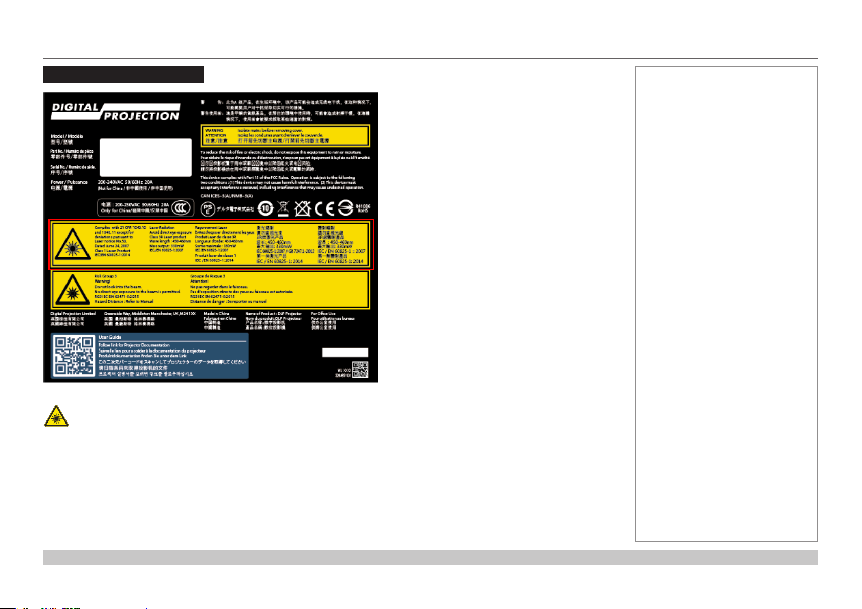
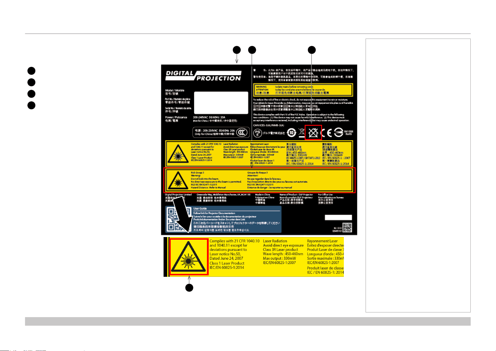
Laser Information
Notes
The outlined section of the product label above provides information about the laser light sources used within the projector.
Caution-useofcontrolsoradjustmentsorperformanceofproceduresotherthanthosespeciedhereinmayresultin
hazardous radiation exposure.
Rev A October 2018
page ii
Page 4
Digital Projection INSIGHT Laser 8K Series
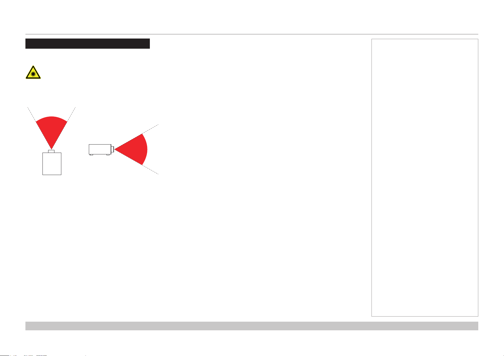
Risk Group 3 Information
Light hazard warning
Failure to comply with the following may result in serious injury:
• No direct exposure to the beam is permitted, RG3 IEC 62471-5:2015.
• Operatorscontrolaccesstothebeamwithinthehazarddistanceorinstalltheprojectoratsucientheighttoprevent
exposures of spectators’ eyes within the hazard distance.
Fig. 1: hazard distance
The hazard distance (Fig. 1) is the distance measured from the projection lens at which the intensity or energy per unit of surface is lower
than the applicable exposure limit on the cornea or skin. If the person is within the hazard distance, the beam is considered unsafe for
exposure.
The hazard distance for this projector is 12m.
Notes
Rev A October 2018
page iii
Page 5
Digital Projection INSIGHT Laser 8K Series
Light hazard labels on the body of the projector
Light hazard labelling is part of the product label.
Product label
1
Risk Group 3 label
2
Not For Home Use logo
3
Hazard Warning symbol
4
1 3
2
Notes
4
Rev A October 2018
page iv
Page 6

Digital Projection INSIGHT Laser 8K Series
Introduction
Congratulations on your purchase of this Digital Projection product.
Your projector has the following key features:
• 8K (7680 x 4320) resolution up to 60 fps.
• Dual laser light source for long-life low-maintenance operation.
• 16x3G-SDI or 4x12G-SDI input capability.
• Colour management includes Colourmax.
• HDR and HLG management.
• Blanking control for custom input window sizing.
• Built-in web served control application.
• Control via LAN and RS232.
• Motorised lens mount.
A serial number is located on the product label. Record it here:
Notes
Rev A October 2018
page v
Page 7

Digital Projection INSIGHT Laser 8K Series
CONTENTS
INSTALLATION AND QUICK-START GUIDE ..........................1
CONNECTING THE POWER SUPPLY ........................................... 3
PROJECTOR OVERVIEW ............................................................. 4
Front and rear views ............................................................................. 4
Keypad .................................................................................................. 5
Keypad references ................................................................................. 5
Keypad indicators .................................................................................. 6
Remote control ...................................................................................... 7
POSITIONING THE SCREEN AND PROJECTOR ....................... 10
Tilt ....................................................................................................... 11
ESSENTIAL MAINTENANCE ...................................................... 12
Fitting the lens ..................................................................................... 12
Fitting a lens hood ............................................................................... 13
Replacing the lters............................................................................. 15
OPERATING THE PROJECTOR ................................................. 16
Switching the projector on ................................................................... 16
Switching the projector o ................................................................... 16
Selecting an input signal ..................................................................... 16
Adjusting the lens ................................................................................ 17
Orientation ......................................................................................... 17
Picture .............................................................................................. 17
OPERATING GUIDE ..............................................................................23
MAIN MENU ................................................................................ 25
INPUT MENU .............................................................................. 26
Input Select ......................................................................................... 26
Format Select ...................................................................................... 27
Transfer Format .................................................................................. 27
Colour Space ...................................................................................... 28
TEST PATTERN .......................................................................... 29
LENS MENU ................................................................................ 30
Lens Lock ............................................................................................ 30
Lens Memory ...................................................................................... 31
IMAGE MENU .............................................................................. 32
Gamma SDR / HDR ............................................................................ 32
Gain and Lift ........................................................................................ 33
COLOR MENU ............................................................................. 34
ColorMax ............................................................................................. 34
Manual Color Matching ....................................................................... 34
ALIGNMENT MENU .................................................................... 36
Blanking .............................................................................................. 36
LASER MENU ............................................................................. 37
Power Mode ........................................................................................ 37
CONNECTION GUIDE ..........................................................................18
SIGNAL INPUTS ......................................................................... 20
CONTROL CONNECTIONS ......................................................... 21
SETUP MENU ............................................................................. 38
ColorMax ........................................................................................... 39
Power On/O ...................................................................................... 40
OSD Settings ...................................................................................... 40
Memory ............................................................................................. 41
NETWORK MENU ....................................................................... 42
Rev A October 2018
page vi
Page 8

Digital Projection INSIGHT Laser 8K Series
CONTENTS (continued)
INFORMATION MENU ................................................................. 43
Input Status ......................................................................................... 44
Thermal Status .................................................................................... 44
System Status ..................................................................................... 45
Factory Reset ...................................................................................... 45
REFERENCE GUIDE ..............................................................................46
CHOOSING A LENS .................................................................... 48
Throw Ratios for 8K or 4K-UHD .......................................................... 48
Throw Ratios for 4K ............................................................................ 48
SCREEN REQUIREMENTS ......................................................... 49
Fitting the image to the DMD™ ........................................................... 49
POSITIONING THE IMAGE ......................................................... 50
Maximum oset range ......................................................................... 52
Oset for 8K or 4K-UHD ........................................................................ 52
Oset for 4K ....................................................................................... 52
ASPECT RATIOS EXPLAINED ................................................... 53
APPENDIX A: LENS PART NUMBERS ....................................... 54
Lens Parts for 8K or 4K-UHD .............................................................. 54
Lens Parts for 4K ................................................................................ 55
3G-SDI or 12G-SDI In, 3G-SDI or 12G-SDI Out ........................................... 57
Control connections ............................................................................ 57
LAN ................................................................................................. 57
RS232 .............................................................................................. 57
APPENDIX E: GLOSSARY OF TERMS ....................................... 58
APPENDIX C: SUPPORTED SIGNAL INPUT MODES ................ 56
APPENDIX D: WIRING DETAILS ............................................... 57
Signal inputs........................................................................................ 57
Rev A October 2018
page vii
Page 9
INSIGHT Laser 8K Series
High Brightness Digital Video Projector
4
INSTALLATION AND QUICK-START GUIDE
Rev A October 2018
Page 10

Digital Projection INSIGHT Laser 8K Series
IN THIS GUIDE
IN THIS GUIDE
Connecting The Power Supply ........................................................................ 3
Projector Overview ............................................................................................. 4
Front and rear views ...................................................................................................4
Keypad .........................................................................................................................5
Keypad references ............................................................................................................ 5
Keypad indicators ............................................................................................................. 6
Remote control ............................................................................................................7
Positioning The Screen And Projector ....................................................... 10
Tilt ...............................................................................................................................11
Essential Maintenance .................................................................................... 12
Fitting the lens ...........................................................................................................12
Fitting a lens hood ....................................................................................................13
Replacingthelters ..................................................................................................15
Operating The Projector ................................................................................. 16
Switching the projector on .......................................................................................16
Switchingtheprojectoro .......................................................................................16
Selecting an input signal ..........................................................................................16
Adjusting the lens .....................................................................................................17
Orientation ......................................................................................................................17
Picture .............................................................................................................................17
Installation and Quick-Start Guide
Rev A October 2018
Page 11
Digital Projection INSIGHT Laser 8K Series
CONNECTING THE POWER SUPPLY
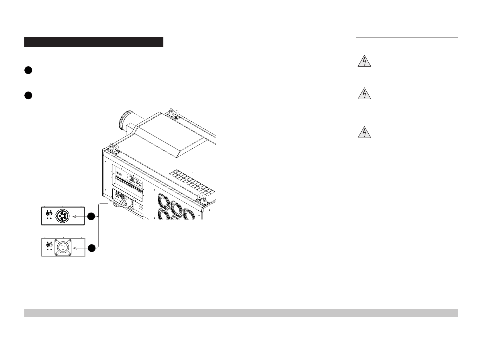
Connecting The Power Supply
Rest of the world:
1
Firmly push the mains connector into the socket.
USA only:
2
Firmly push the mains connector into the socket.
Rotate the connector 20° clockwise to lock it in place
Notes
Use only the power cable
provided.
Ensure that the power outlet
includes a ground connection as
this equipment MUST be earthed.
Handle the power cable carefully
and avoid sharp bends. Do not
use a damaged power cable.
1
2
Installation and Quick-Start Guide
Rev A October 2018
page 3
Page 12
Digital Projection INSIGHT Laser 8K Series
PROJECTOR OVERVIEW
Projector Overview
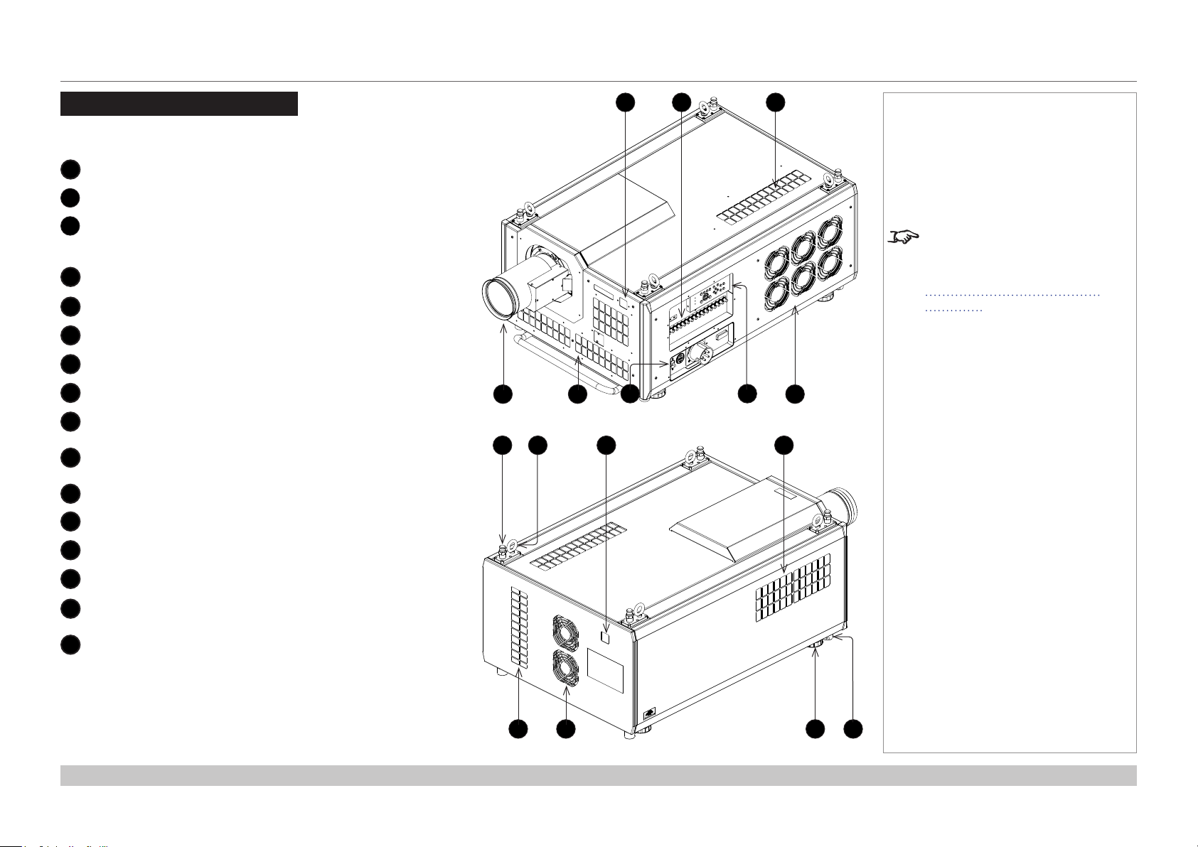
Front and rear views
1
Front IR window
2
Inputs
3
Air inlet
An identical air inlet is located at the bottom of the projector,
right below this one.
4
Lens
5
Air inlets
6
Mains plug with switch and voltage meter
7
Keypad
8
Air outlet
9
Top stacking point
There are four top stacking points: one in each corner.
10
Lifting ring
There are four lifting rings: one in each corner.
11
Rear IR window
4
9 11 1210
1
6
Front view
2 3
7
Notes
The air inlet at the bottom of
the projector can be seen in the
illustration at the beginning of
Positioning The Screen And
Projector further in this guide.
85
12
Air inlet
13
Air inlet
14
Air outlet
15
Adjustable foot
There are four adjustable feet: one in each corner.
16
Bottom stacking point
There are four bottom stacking points: one in each corner.
Installation and Quick-Start Guide
15 1613 14
Rear view
Rev A October 2018
page 4
Page 13
Digital Projection INSIGHT Laser 8K Series
PROJECTOR OVERVIEW
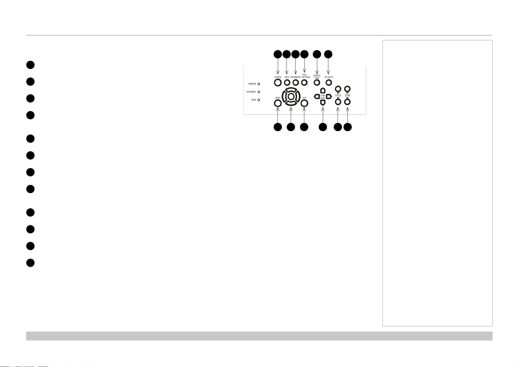
Keypad
Keypad references
POWER
1
Switches the projector on and o (STANDBY).
INPUT
2
Switches to the next input source.
INFORMATION
3
Displays .
TEST PATTERN
4
Cycles through the test patterns ...O, White, Black, Red, Green, Blue,
CheckerBoard, Grid, ColorBars, Cyan, Yellow, Magenta, Ramp...
CENTER LENS
5
Centers the lens.
PIC MUTE
6
Switches the laser o/on.
MENU
7
Displays and exits the OSD.
Arrow buttons & ENTER
8
Navigation buttons used to highlight menu entries in the OSD.
Press ENTER to open or execute the highlighted menu entry.
EXIT
9
Exits the current OSD page and enters the level above.
LENS SHIFT arrow buttons
10
Each of these buttons moves the lens in the specied direction.
FOCUS plus and minus buttons
11
Used to move the focus in and out.
ZOOM plus and minus buttons
12
Used to zoom in and out.
Notes
1 2 3 4 5 6
7 8 9 10 11 12
Installation and Quick-Start Guide
Rev A October 2018
page 5
Page 14
Digital Projection INSIGHT Laser 8K Series
PROJECTOR OVERVIEW
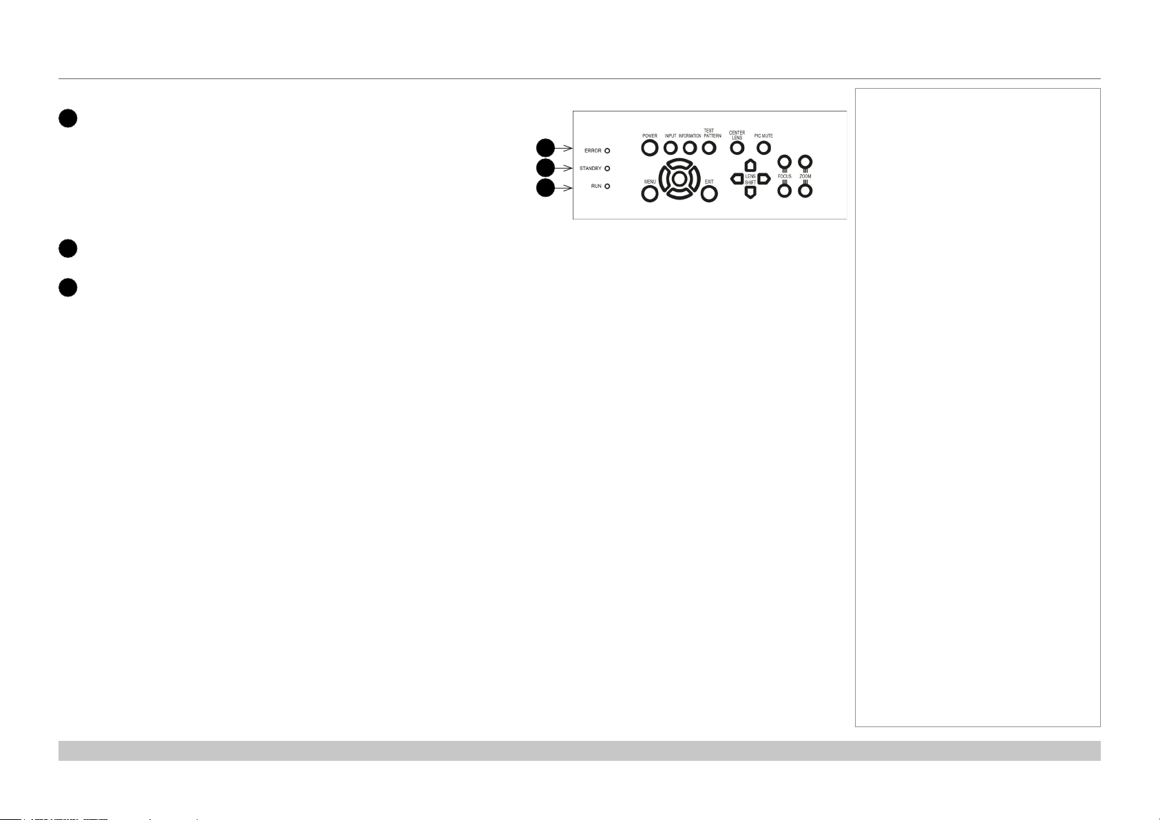
Keypad indicators
1
ERROR
A red indicator that shows the following patterns:
O = No Error
Single ash followed by a pause = Lamp abnormality
Double ash followed by a pause = Uncovered lamp cover
Triple ash followed by a pause = Fan abnormality
Four ashes followed by a pause = Overheat
A continuous light = System abnormality
2
STANDBY
A green indicator that shows a continuous light when standby mode is activated
3
RUN
A blue indicator that shows the following patterns:
O = Power is o
Flashing = Projector is cooling down during power o, or warming up during power on
A continuous light = Power is on
Notes
1
2
3
Installation and Quick-Start Guide
Rev A October 2018
page 6
Page 15
Digital Projection INSIGHT Laser 8K Series
PROJECTOR OVERVIEW
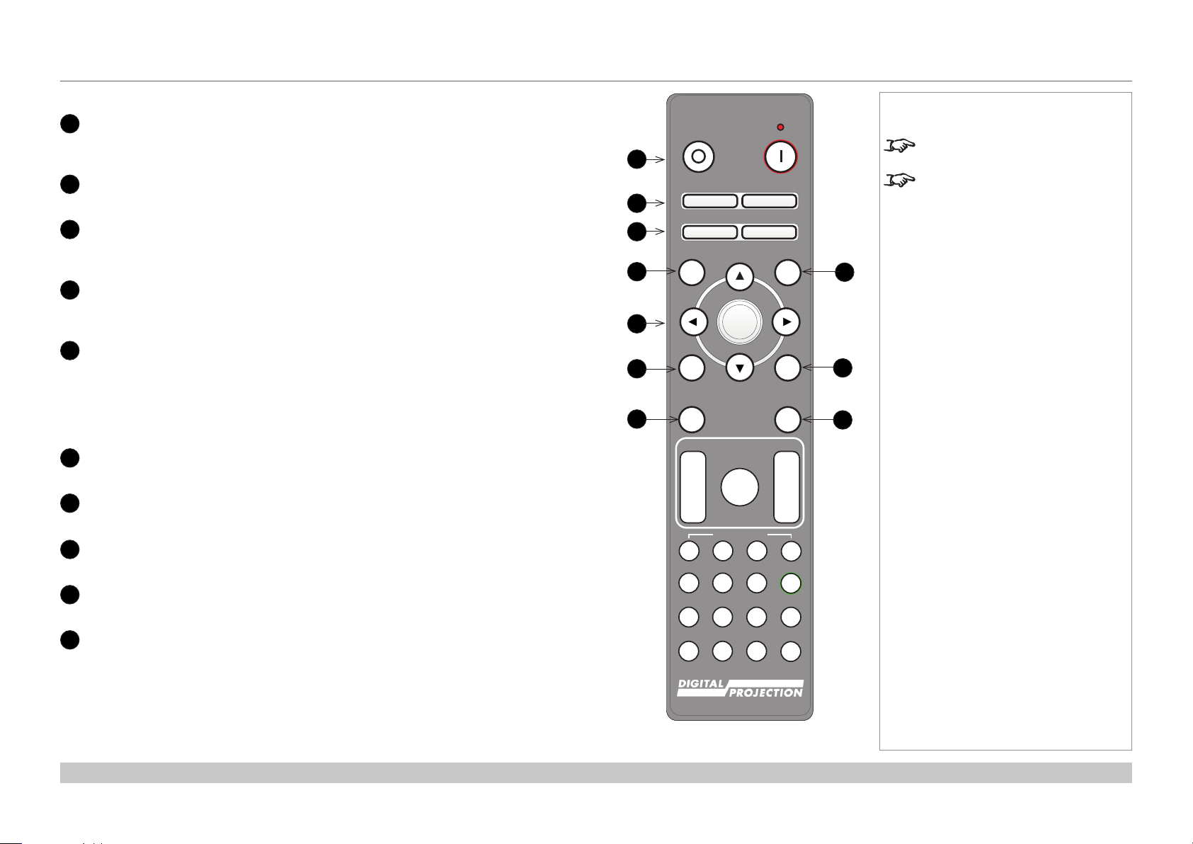
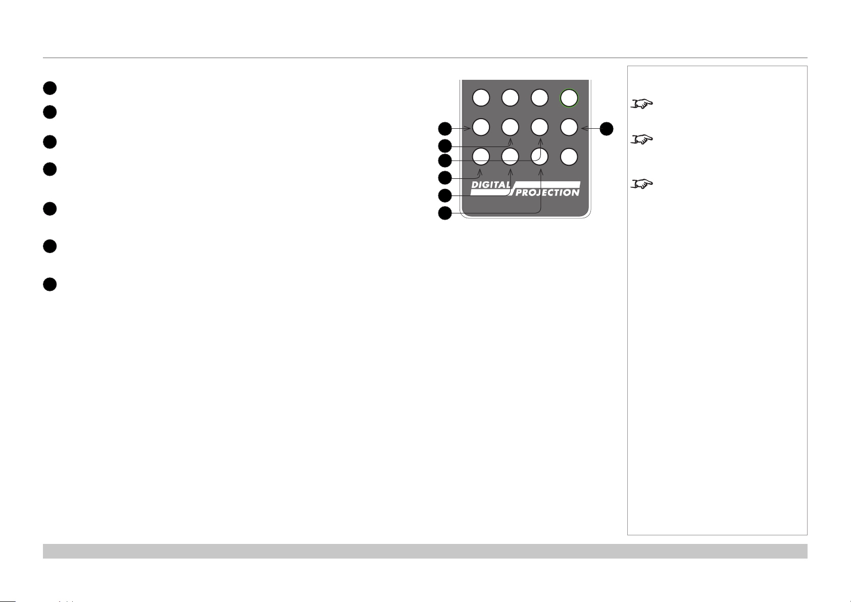
Remote control
1
Power ON/OFF
Turns the projector on and o.
To turn the projector o, press the OFF button twice within ve seconds.
2
Pic Mute OPEN / CLOSE
Shows and hides the projected image.
3
OSD ON / OFF
Enables and disables screen timeout messages and showing the OSD during
projection.
4
MENU
Access the projector OSD (on-screen display). If the OSD is open, press this button to
go back to the previous menu.
5
Navigation (arrows and OK)
Navigate through the menus with the arrows, conrm your choice with OK.
In lens adjustment modes, the arrows are used to move, zoom or focus the lens. See
11 below.
In lens adjustment modes, or when the OSD is not showing, the OK button switches
between modes: Shift Adjustment and Zoom / Focus Adjustment.
6
EXIT
Close the current OSD page and return to the level above.
7
FREEZE
Freeze the current frame.
8
DEFAULT
Restore default settings.
9
INFO
Access information about the projector.
10
RE-SYNC
Re-synchronise with the current input signal.
Notes
OFF ON
1
Pic Mute
2
3
4
5
6
7
OPEN CLOSE
OSD
OFF
MENU
ON
DEFAULT
OK
EXIT INFO
FREEZE
FOCUS ZOOM
LENS
IN
SHIFT
OUT
USER PRESET
RE-SYNC
8
9
10
IN
OUT
A B C D
HDMI2 DVI
HDMI1
BRI
DISPLAYPORT
21 3
CON GAMMA
HD-T 3GSDI
ALT
ALT
ADDR
4 5 6
R G B ALL
VGA COMP1 COMP2
7 8 9 0
3D EYE PIP SWAP
TEST
Not all keys are used on this
projector.
You can use the remote control with
a standard TRS cable connected to
the Wired Remote In connector.
Installation and Quick-Start Guide
Rev A October 2018
page 7
Page 16
Digital Projection INSIGHT Laser 8K Series
Pic Mute
MENU
EXIT INFO
OK
OFF ON
OSD
OFF
ON
DEFAULT
FREEZE
RE-SYNC
OPEN CLOSE
PROJECTOR OVERVIEW
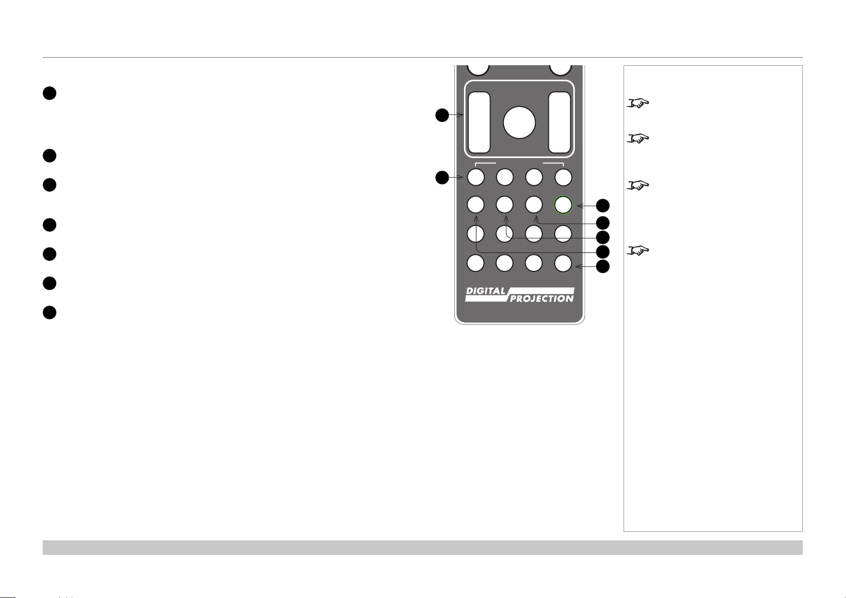
Remote control continued
11
LENS adjustment
FOCUS IN / OUT: adjust focus.
SHIFT: press and hold this button, then use the Navigation arrow buttons to move
the lens.
ZOOM IN / OUT: adjust zoom.
12
USER PRESET A, B, C, D
Load user presets.
Press and hold this button to access alternative functions for all buttons with a green
13
ALT
label.
14
DVI / DisplayPort2 / numeric input 3
There is no DVI or DisplayPort2 input on this projector.
15
HDMI 2 / HDMI 4 / numeric input 2
There is no HDMI 2 or HDMI 4 input on this projector.
16
HDMI 1 / HDMI 3 / numeric input 1
There is no HDMI 1 or HDMI 3 input on this projector.
17
TEST / SWAP / numeric input 0
Show a test pattern. Press again to show the next test pattern:
...O, White, Black, Red, Green, Blue, CheckerBoard, Grid, ColorBars, Cyan,
Yellow, Magenta, Ramp...
11
12
FOCUS ZOOM
IN
LENS
SHIFT
OUT
USER PRESET
A B C D
HDMI2 DVI
HDMI1
21 3
HDMI3
HDMI4
DisplayPort2
DisplayPort1
HD-T
SDI
4 5 6
R G B ALL
VGA COMP1 COMP2 TEST
7 8 9 0
3D EYE PIP SWAP
IN
OUT
ALT
ALT
ADDR
Notes
Not all keys are used on this
projector. The unused keys are
grayed out.
You can use the remote control
wirelessly or with a standard TRS
cable connected to the Wired
Remote In connector.
When adjusting focus or zoom,
UP and LEFT will focus/zoom
13
14
15
16
17
in, DOWN and RIGHT will zoom
out. When adjusting shift, each
arrow key moves the image in the
corresponding direction.
This projector does not use the
following options on the remote:
HDMI1, HDMI2, HDMI3, HDMI4,
DVI, DisplayPort2, DisplayPort1,
HD-T, SDI, VGA, 3D, COMP 1, EYE
and COMP 2.
Installation and Quick-Start Guide
Rev A October 2018
page 8
Page 17
Digital Projection INSIGHT Laser 8K Series
Pic Mute
MENU
EXIT INFO
OK
OFF ON
LENS
FOCUS ZOOM
IN
OUT
IN
OUT
SHIFT
OSD
OFF
ON
DEFAULT
FREEZE
RE-SYNC
A B C D
USER PRESET
OPEN CLOSE
PROJECTOR OVERVIEW
Remote control continued
19
There is no DisplayPort1 input on this projector.
HD-T /G/ numeric input 5
DisplayPort1 /R/ numeric input 4
18
There is no HDBaseT input on this projector.
SDI /B/ numeric input 6
20
21
22
There is no SDI input on this projector.
VGA /3D/ numeric input 7
There is no VGA input on this projector.
There is no 3D function on this projector.
COMP1 /EYE/ numeric input 8
There is no COMP1 input on this projector.
There is no EYE function on this projector.
COMP2 /PIP/ numeric input 9
23
There is no COMP2 input on this projector.
There is no PIP function on this projector.
ADDR / ALL
24
Assign and unassign an IR remote address.
To assign an address:
1. Press and hold this button until the indicator starts ashing.
2. Release this button and while the indicator is still ashing, enter a two-digit
address using the numeric input buttons. The indicator will ash three times
quickly to conrm the change.
To unassign an address and return to the default address 00,
• Press and hold ALT and this button simultaneously until the indicator ashes to
conrm the change.
Notes
HDMI2 DVI
HDMI1
21 3
HDMI3
HDMI4
DisplayPort2
DisplayPort1
18
19
20
21
22
23
HD-T
4 5 6
R G B ALL
VGA COMP1 COMP2 TEST
7 8 9 0
3D EYE PIP SWAP
SDI
ALT
ALT
ADDR
Not all keys are used on this
projector. The unused keys are
24
grayed out.
You can use the remote control
wirelessly or with a standard TRS
cable connected to the Wired
Remote In connector.
This projector does not use the
following options on the remote:
HDMI1, HDMI2, HDMI3, HDMI4,
DVI, DisplayPort2, DisplayPort1,
HD-T, SDI, VGA, 3D, COMP 1, EYE
and COMP 2.
Installation and Quick-Start Guide
Rev A October 2018
page 9
Page 18
Digital Projection INSIGHT Laser 8K Series
POSITIONING THE SCREEN AND PROJECTOR
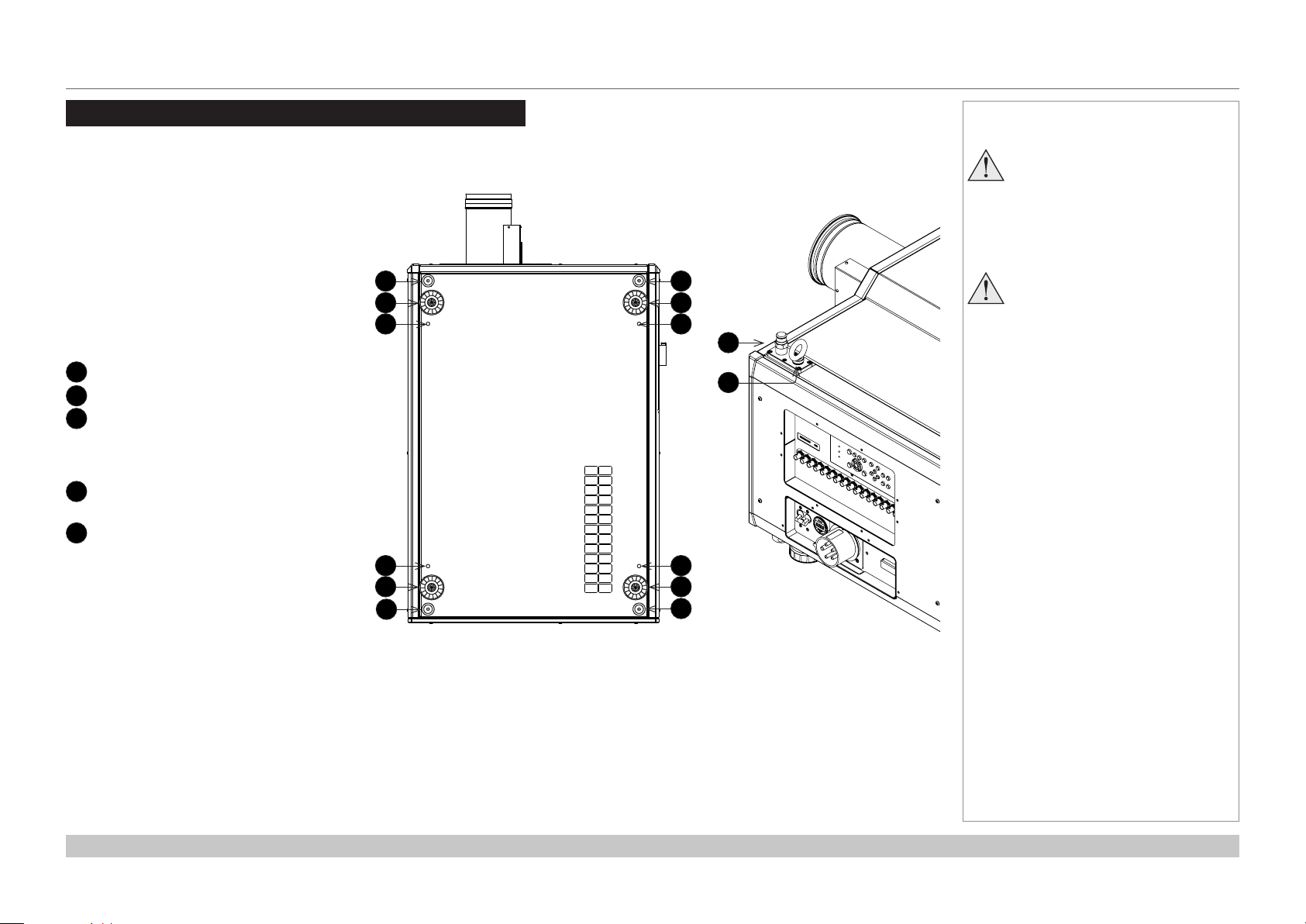
Positioning The Screen And Projector
1. Install the screen, ensuring that it is in the best
position for viewing by your audience.
2. Mount the projector, ensuring that it is at a
suitable distance from the screen for the image
to ll the screen. Set the adjustable feet so that
the projector is level, and perpendicular to the
screen.
The drawings below shows the feet for table
mounting, and the xing holes for ceiling mounting.
Also shown is one of four rings each located in the
top corners. These can be used for lifting a single
projector.
1
2
3
Four stacking points
Four adjustable feet
Four M10 holes for ceiling mount
The screws should not penetrate
more than 18 mm into the body of
the projector.
4
Stacking point at the top of the
projector
5
Lifting ring (for handling a single
projector)
The rings can be removed to reveal
M10 x 18 deep holes for ceiling
mounting.
1
2
3
3
2
1
Bottom view of the projector Top corner (detail)
Notes
Always allow the projector
to cool for 5 minutes before
disconnecting the power or
moving the projector.
1
2
3
4
5
3
2
1
Ensure that there is at least 30
cm (12 in) of space between the
ventilation outlets and any wall,
and 10 cm (4 in) on all other
sides.
Installation and Quick-Start Guide
Rev A October 2018
page 10
Page 19
Digital Projection INSIGHT Laser 8K Series
POSITIONING THE SCREEN AND PROJECTOR
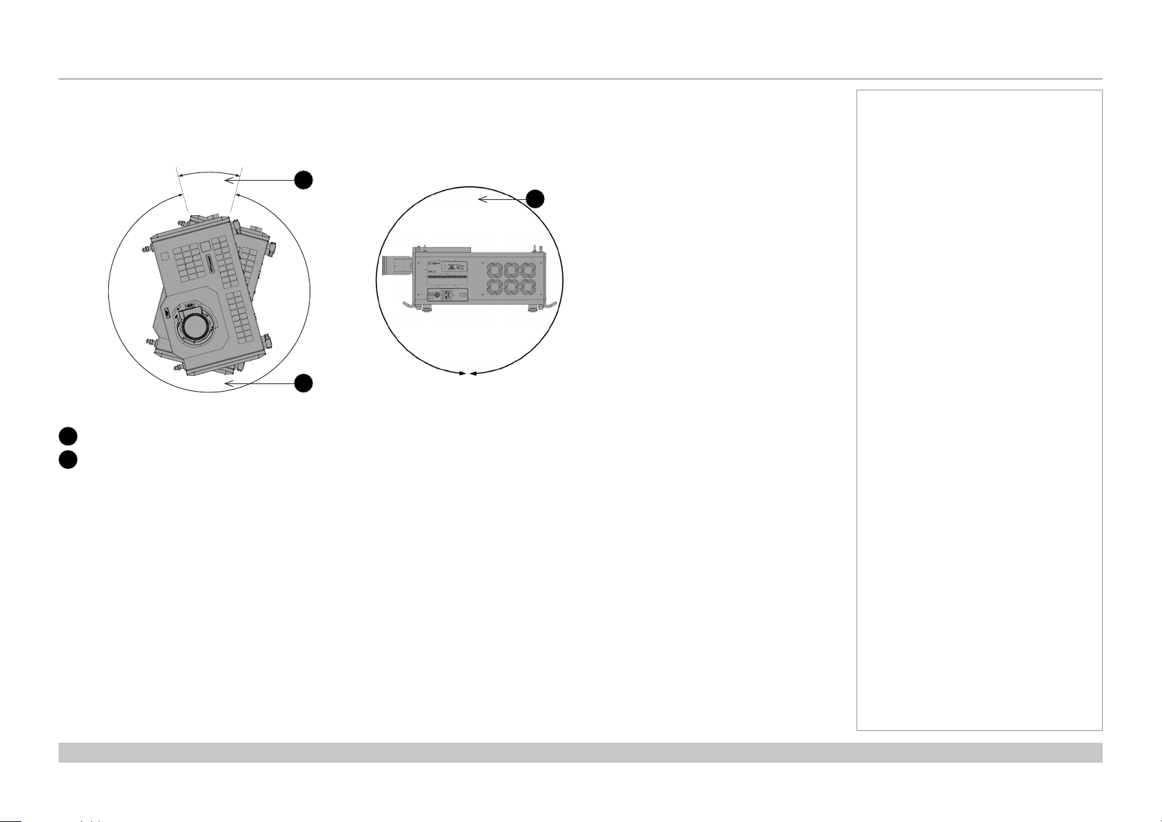
Tilt
The projector can be operated in numerous positions.
It is recommended to position the projector in portrait mode with inputs facing upward, as shown in the diagram:
30°
330°
Roll
1
2
Recommended positions, inputs side up
Also possible
1
360°
2
Pitch
2
Notes
Installation and Quick-Start Guide
Rev A October 2018
page 11
Page 20
Digital Projection INSIGHT Laser 8K Series
ESSENTIAL MAINTENANCE
Essential Maintenance
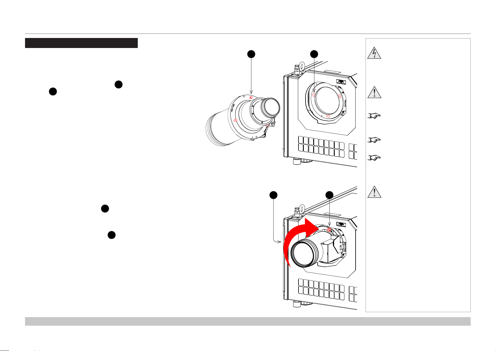
Fitting the lens
1. Insert the lens into the mount.
Engage the three locating studs 1 into the corresponding
slots 2 on the mount.
2. Rotate the lens clockwise 3 until the studs slide all the way
into the slots.
Notes
21
43
Before changing the lens,
always make sure the projector
isswitchedoandfully
disconnected from its power
supply.
When changing the lens, avoid
using excessive force as this may
damage the equipment.
Take care to preserve the original
lens packaging and protective caps
for future use.
The projector will not power on
without the lens tted.
Before turning on the projector,
please ensure the protective caps
are removed from the front and rear
of the lens.
Thetwoxingscrewsmustbe
tightened to at least a torque
of 0.5 N-m using a screwdriver.
Loose screws might lead to the
lensfallingo.
3. Tighten the two xing screws 4 on the lens collar.
To remove the lens, reverse the above procedure.
Installation and Quick-Start Guide
Rev A October 2018
page 12
Page 21
Digital Projection INSIGHT Laser 8K Series
ESSENTIAL MAINTENANCE
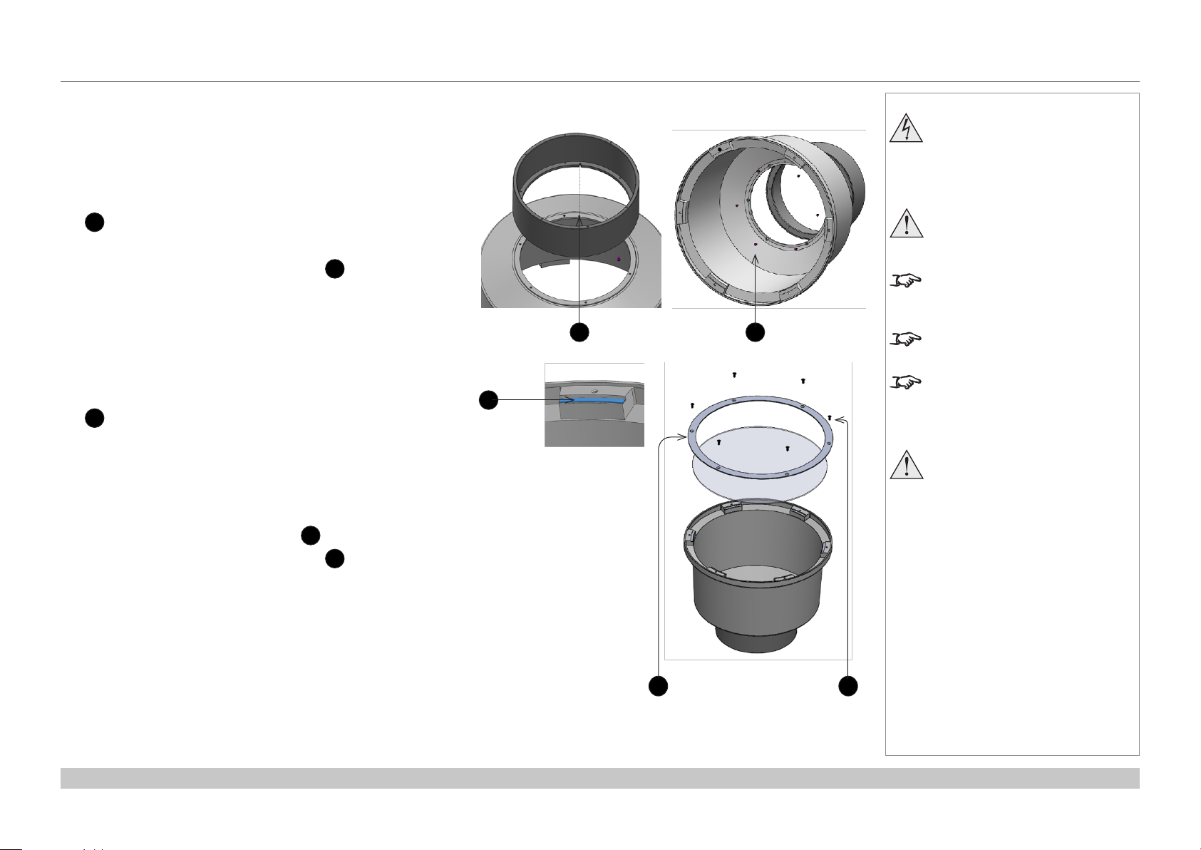
Fitting a lens hood
A lens hood must be tted to the lens (P/N 115-632) for use in the
USA.
1. Place the adaptor ring to the rear of the lens case.
Use the guide pin to ensure it is located correctly.
1
2. Insert and tighten the six xing screws 2 to secure the
adaptor ring to the lens case.
3. Place the glass lens over the lens case.
Ensure the glass is located correctly.
3
4. Place the plate over the glass lens. 4
5. Insert and tighten the six xing screws 5 to secure the plate
and glass lens to the lens case.
Notes
Before changing the lens,
always make sure the projector
isswitchedoandfully
disconnected from its power
supply.
When changing the lens, avoid
using excessive force as this may
damage the equipment.
Take care to preserve the original
lens packaging and protective caps
for future use.
1
3
2
The projector will not power on
without the lens tted.
Before turning on the projector,
please ensure the protective caps
are removed from the front and rear
of the lens.
Thetwoxingscrewsmustbe
tightened to at least a torque
of 0.5 N-m using a screwdriver.
Loose screws might lead to the
lensfallingo.
Installation and Quick-Start Guide
4 5
Rev A October 2018
page 13
Page 22
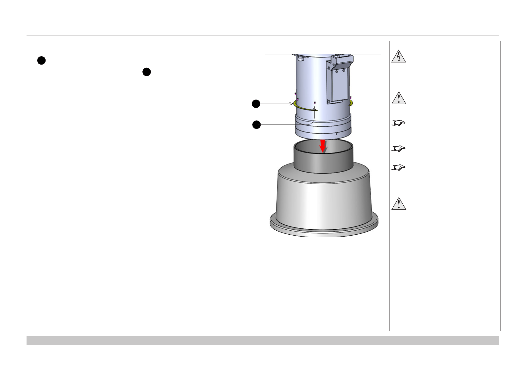
Digital Projection INSIGHT Laser 8K Series
6. Insert the lens into the adaptor ring.
6
Push-t the lens until the plate ring is located against the adapter ring.
7. Insert and tighten the six xing screws 7 to secure the lens and to the lens
hood.
ESSENTIAL MAINTENANCE
Notes
Before changing the lens,
always make sure the projector
isswitchedoandfully
disconnected from its power
supply.
6
7
When changing the lens, avoid
using excessive force as this may
damage the equipment.
Take care to preserve the original
lens packaging and protective caps
for future use.
The projector will not power on
without the lens tted.
Before turning on the projector,
please ensure the protective caps
are removed from the front and rear
of the lens.
Thetwoxingscrewsmustbe
tightened to at least a torque
of 0.5 N-m using a screwdriver.
Loose screws might lead to the
lensfallingo.
Installation and Quick-Start Guide
Rev A October 2018
page 14
Page 23
Digital Projection INSIGHT Laser 8K Series
ESSENTIAL MAINTENANCE
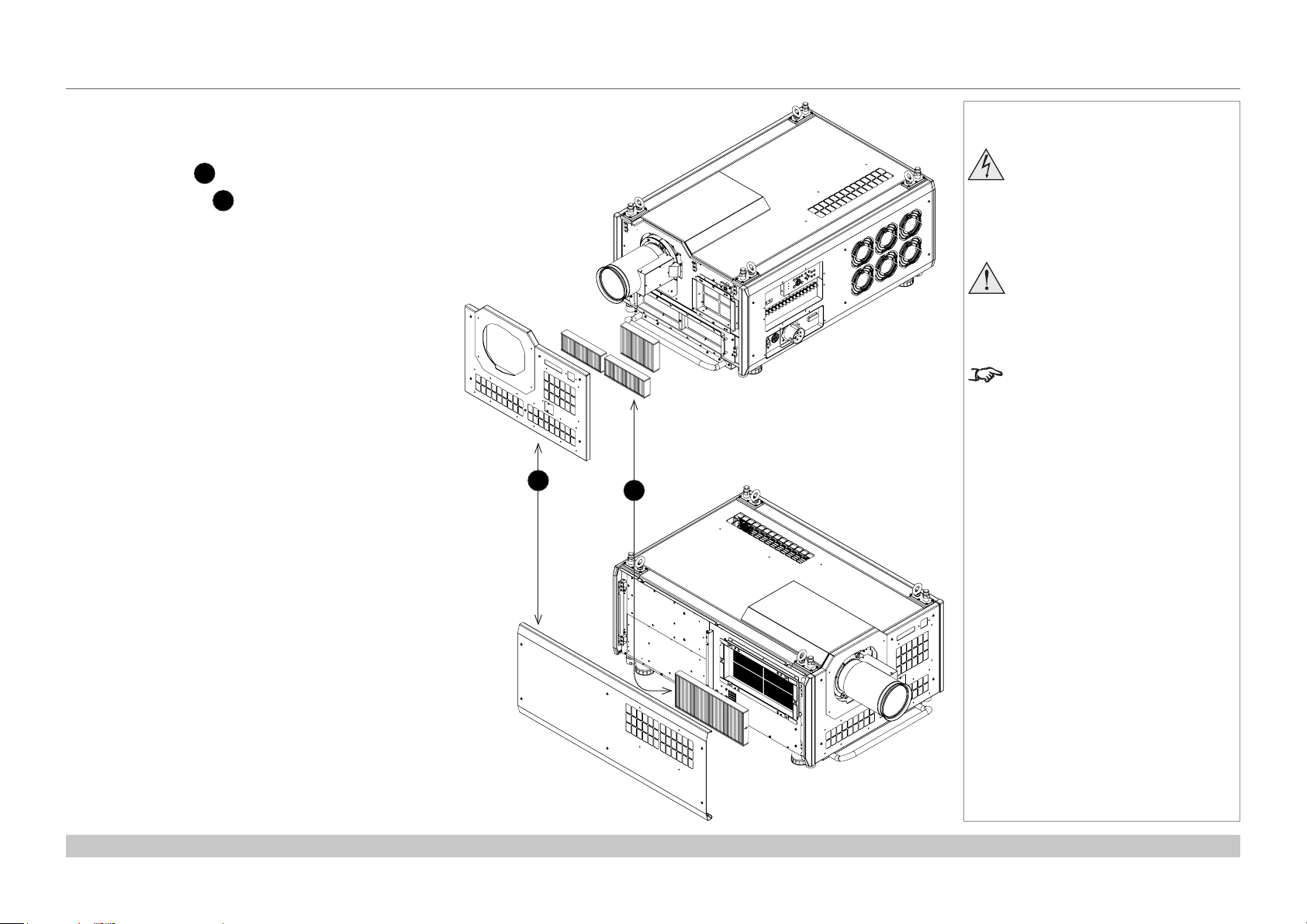
Replacing the lters
1. Loosen the six captive screws, then remove the
front/side panel 1.
2. Replace the lters 2.
3. Reattach the panel and tighten the screws.
Notes
Beforechangingthelters,
always make sure the projector
isswitchedoandfully
disconnected from its power
supply.
Whenchangingthelters,avoid
using excessive force as this may
damage the equipment.
Filters should be replaced as
necessary upon visual inspection
and in accordance with operating
environment.
1
2
Installation and Quick-Start Guide
Rev A October 2018
page 15
Page 24

Digital Projection INSIGHT Laser 8K Series
OPERATING THE PROJECTOR
Operating The Projector
Switching the projector on
1. Connect the power cable between the mains supply and the socket 1. Switch on at the
ON/OFF switch 2.
2. Press ON on the remote control or the control panel to switch the projector ON.
The run indicator on the control panel will ash blue until the projector has warmed up. The light
source will light and the shutter will open.
The run indicator will show a continuous blue light and the standby indicator will show green when
the projector has warmed up.
Switching the projector off
1. Press OFF twice on the remote control or the keypad.
The run indicator on the control panel will ash blue until the projector has cooled down. The
cooling fans will run for a short time until the projector enters STANDBY mode.
The run indicator will show a continuous blue light and the standby indicator will show green when
the projector has cooled down.
2. If you need to switch the projector o completely, switch o at the mains power switch next to the
power connector and then disconnect the power cable from the projector.
Selecting an input signal
The last selected input remains active until a new input is selected. To select a new input:
1. Connect ither a 3G-SDI or 12GSDI image source to the projector. Refer to the “Connection Guide”
2. Select the appropriate resolution:
1. Press MENU to open the On-screen display (OSD).
2. Use the UP and DOWN arrow buttons to highlight Input from the main menu and press ENTER/OK.
3. Use the UP and DOWN arrow buttons to highlight Format from the input menu and press ENTER/OK.
4. Use the UP and DOWN arrow buttons to highlight a setting. Choose from Auto, 8K, 4K or HD. Press ENTER/OK to conrm your
choice.
Notes
See also Connecting The Power
Supply earlier in this guide.
Donotturnotheprojectorfrom
the power switch or disconnect
the power cord while the
projector is working or cooling
down.
Use only the power cable
provided.
Ensure that the power outlet
includes a ground connection as
1
2
this equipment MUST be earthed.
Handle the power cable carefully
and avoid sharp bends. Do not
use a damaged power cable.
Installation and Quick-Start Guide
Rev A October 2018
page 16
Page 25

Digital Projection INSIGHT Laser 8K Series
OPERATING THE PROJECTOR
Adjusting the lens
The lens can be adjusted using the lens buttons on the keypad or remote control.
On either device, press FOCUS, ZOOM or SHIFT, then use the arrow keys to adjust the lens.
Adjusting the image
Orientation
Set the orientation setting from the OSD menu:
1. Press MENU to open the On-screen display (OSD).
2. Use the UP and DOWN arrow buttons to highlight Setup from the main menu and press ENTER/OK.
3. Use the UP and DOWN arrow buttons to highlight Projection Mode from the setup menu and press ENTER/OK.
4. Use the UP and DOWN arrow buttons to highlight a setting. Choose from Front Desktop, Front Ceiling, Rear Desktop or Rear
Ceiling. Press ENTER/OK to conrm your choice.
Picture
Settings such as Gamma, Brightness and Contrast can be set from the Image menu.
1. Press MENU to open the On-screen display (OSD).
2. Use the UP and DOWN arrow buttons to highlight Image from the main menu and press ENTER/OK.
3. Use the UP and DOWN arrow buttons to highlight a setting. Press ENTER/OK to access the setting menu or use the RIGHT and
LEFT arrow buttons to adjust a setting.
Notes
Installation and Quick-Start Guide
Rev A October 2018
page 17
Page 26
INSIGHT Laser 8K Series
High Brightness Digital Video Projector
4
CONNECTION GUIDE
Rev A October 2018
Page 27

Digital Projection INSIGHT Laser 8K Series
IN THIS GUIDE
IN THIS GUIDE
Signal Inputs ....................................................................................................... 20
Control Connections ........................................................................................ 21
Connection Guide
Rev A October 2018
Page 28
Digital Projection INSIGHT Laser 8K Series
SIGNAL INPUTS
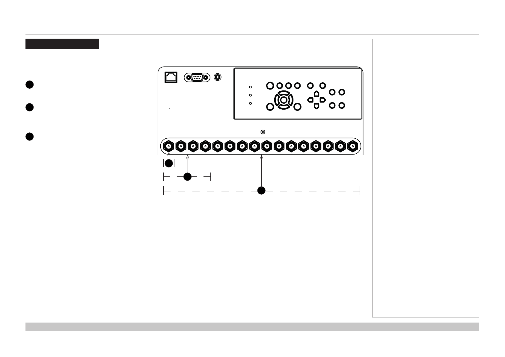
Signal Inputs
The following inputs are available on the connections
panel:
12G-SDI
1
Insert 1 12G-SDI connector for 4K
12G SDI or 3G-SDI
2
Insert 4 3G-SDI connectors for 4K
Insert 4 12G-SDI connectors for 8K
3G-SDI
3
Insert 16 3G-SDI connectors for 8K
Notes
1
2
3
Connection Guide
Rev A October 2018
page 20
Page 29
Digital Projection INSIGHT Laser 8K Series
CONTROL CONNECTIONS
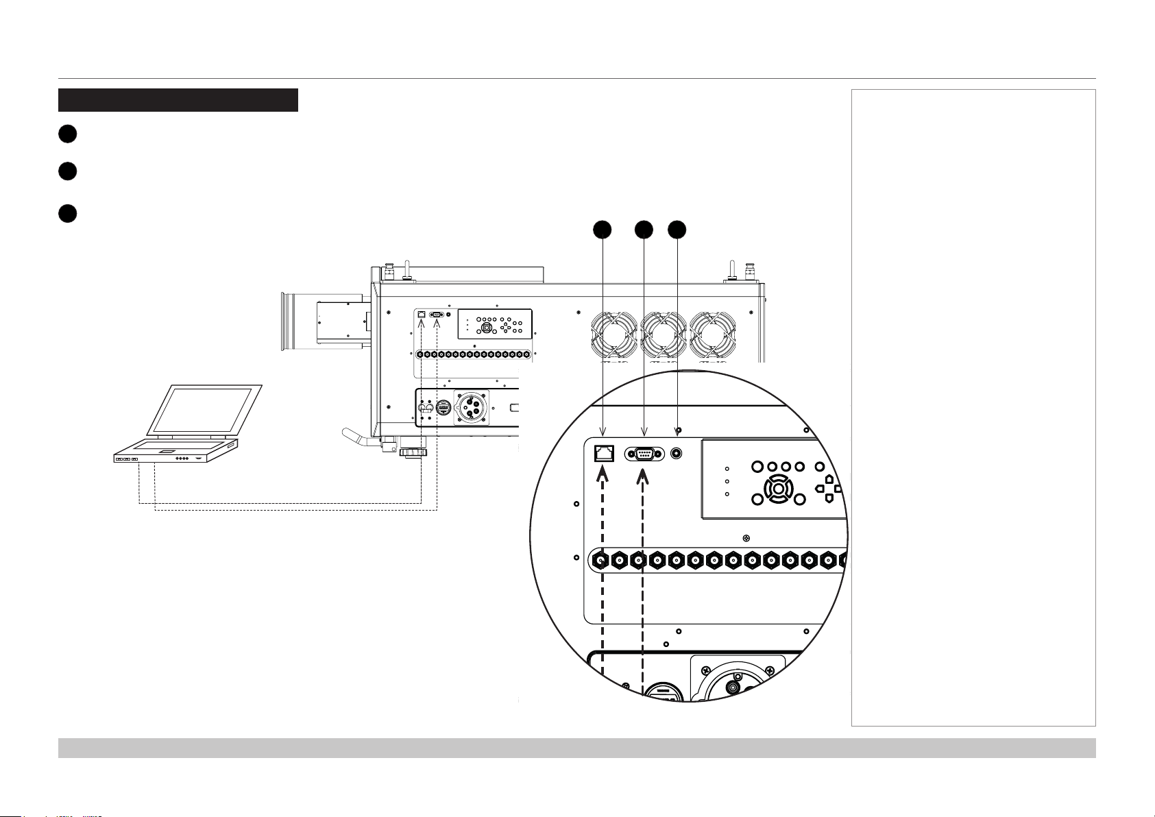
Control Connections
LAN port (LAN)
1
Use this port when controlling the projector in LAN connection from a PC.
PC control terminal (RS-232)
2
Use this terminal when controlling the projector in serial connection from a PC.
Wired Remote (3.5 mm mini jack)
2
Use this port to connect a wired remote control to control the projector. Use
a standard 3.5 mm mini jack cable (tip-ring-sleeve, or TRS).
Notes
1 2 3
Connection Guide
Rev A October 2018
page 21
Page 30

Digital Projection INSIGHT Laser 8K Series
This page is intentionally left blank.
Connection Guide
Page 31
INSIGHT Laser 8K Series
High Brightness Digital Video Projector
4
OPERATING GUIDE
Rev A October 2018
Page 32

Digital Projection INSIGHT Laser 8K Series
IN THIS GUIDE
IN THIS GUIDE
Main Menu ........................................................................................................... 25
Input Menu........................................................................................................... 26
Input Select ................................................................................................................26
Format Select ............................................................................................................27
Transfer Format .........................................................................................................27
Colour Space .............................................................................................................28
Test Pattern ........................................................................................................ 29
Lens Menu ........................................................................................................... 30
Lens Lock ..................................................................................................................30
Lens Memory .............................................................................................................31
Image Menu ........................................................................................................ 32
Gamma SDR / HDR ....................................................................................................32
Gain and Lift ..............................................................................................................33
Color Menu .......................................................................................................... 34
ColorMax ....................................................................................................................34
Manual Color Matching .............................................................................................34
Alignment Menu ................................................................................................. 36
Blanking .....................................................................................................................36
Laser Menu .......................................................................................................... 37
Power Mode ...............................................................................................................37
Thermal Status ..........................................................................................................44
System Status ...........................................................................................................45
Factory Reset ............................................................................................................45
Setup menu ......................................................................................................... 38
ColorMax .........................................................................................................................39
Power On/O ..................................................................................................................40
OSD Settings ..................................................................................................................40
Memory ...........................................................................................................................41
Network Menu .................................................................................................... 42
Information Menu .............................................................................................. 43
Input Status ...............................................................................................................44
Operating Guide
Rev A October 2018
Page 33

Digital Projection INSIGHT Laser 8K Series
MAIN MENU
Main Menu
• Input
Select an input source:
• Test Pattern
Show a test pattern.
• Lens
Adjust lens zoom and focus, use lens presets.
• Image
Open these menus to access various picture and screen settings.
• Colour
Open these menus to access various colour settings.
• Alignment
Open these menus to access various picture alignment settings.
• Laser
Set laser mode and adjust power.
• Setup
Open these menus to access various projector operational settings.
• Network
Access network settings.
• Information
View your current conguration.
MAIN MENU
INPUT >
Input
TEST PATTERN
LENS
IMAGE
COLOR
ALIGNMENT
LASER
SETUP
NETWORK
INFORMATION
HDMI 1
Notes
>
>
>
>
>
>
>
>
>
Operating Guide
Rev A October 2018
page 25
Page 34

Digital Projection INSIGHT Laser 8K Series
INPUT MENU
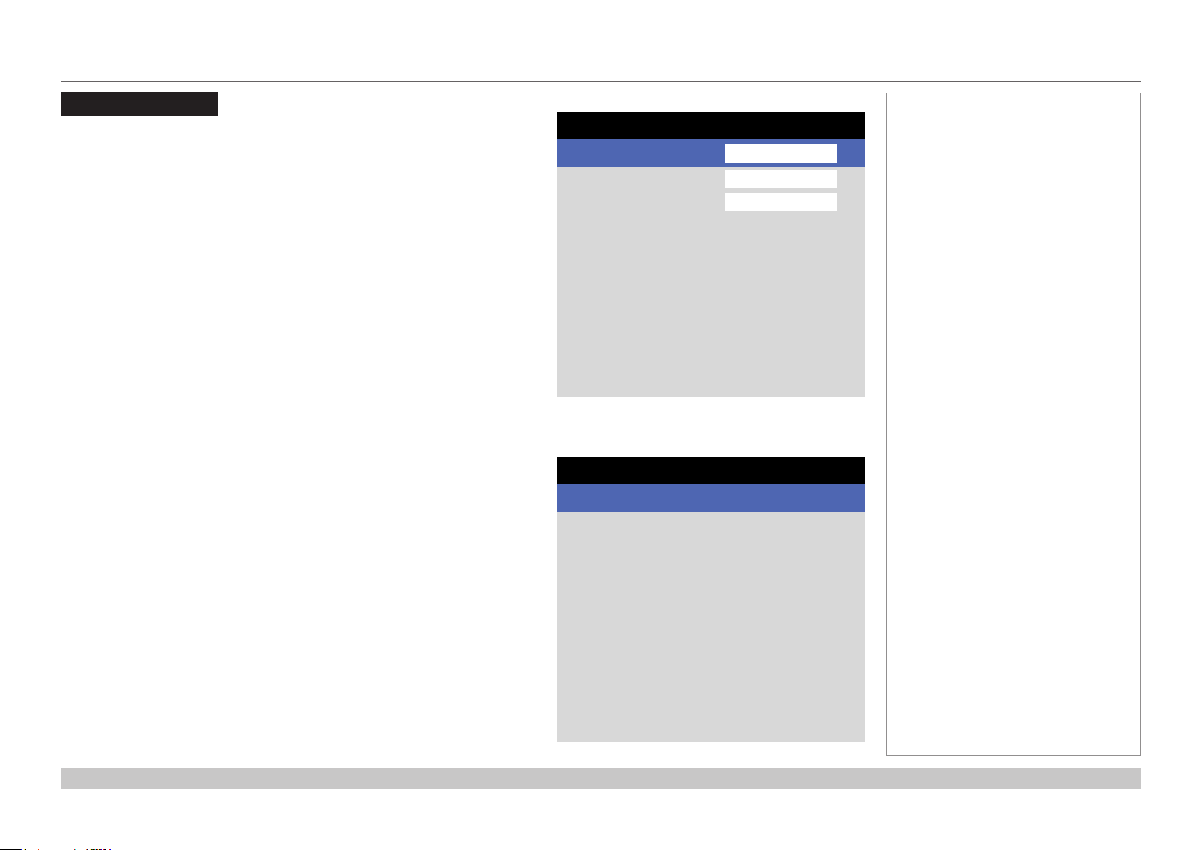
Input Menu
• Input Select
Open this submenu to select the input type.
• Format Select
Open this submenu to select the resolution for the input.
• Transfer Format
Open this submenu to select the SDI data format.
• Colour Space
Open this submenu to select the input colour space.
Input Select
This machine can use 3G-SDI or 12G-SDI inputs only. The setting for this menu is
SDI.
INPUT
Input Select >
Input
Format Select
Transfer Format
Color Space
SDI
HD
Auto
Auto
HDMI 1
Input Select
Auto
Format Select
SDI
DP
Notes
>
>
>
Operating Guide
Rev A October 2018
page 26
Page 35

Digital Projection INSIGHT Laser 8K Series
Format Select
This machine can project at dierent resolutions. These appropriate resolution is
related to the current SDI connections. See “Connection Guide” to determine the
appropriate setting.
Choose from Auto, 8K, 4K or HD
INPUT MENU
Notes
Format Select
Auto
8K
4K
HD
8K 120Hz
Transfer Format
Choose from Auto, 2-SI or SQD
Operating Guide
Auto
Auto
2-SI
SQD
Transfer Format
Rev A October 2018
page 27
Page 36

Digital Projection INSIGHT Laser 8K Series
INPUT MENU
Notes
Colour Space
In most cases, the Auto setting determines the correct colorspace to use. If it does
not, you can choose a specic colorspace:
Choose from Auto, Rec.709 or Rec.2020
Auto
Auto
Rec.709
Rec.2020
Color Space
The optical colour space is limited to
Rec.709. Rec.2020 will be simulated
to show a relative colour spce within
Rec.709 when selected.
Operating Guide
Rev A October 2018
page 28
Page 37

Digital Projection INSIGHT Laser 8K Series
TEST PATTERN
Test Pattern
Press OK to show a test pattern
Choose from..Off, White, Black, Red, Green, Blue, CheckerBoard, Grid,
ColorBars, Cyan, Yellow, Magenta, Ramp...
Notes
Test Pattern
WARNING
Please use EXIT key to exit from test pattern
Press OK to confirm
Press EXIT to cancel
Operating Guide
Rev A October 2018
page 29
Page 38

Digital Projection INSIGHT Laser 8K Series
LENS MENU
Lens Menu
• Lens Lock
Select to lock or unlock the lens.
• Lens Control
Select to access Zoom/Focus and Shift controls.
• Center Lens
Select to center the lens.
• Lens Memory
Select to save and load lens settings, or clear the lens settings memory.
Lens Lock
This menu allows you to switch the lens lock on or o.
Swithc the lens lock on to prevent changes to the lens shift, zoom and focus
settings
LENS
Lens Lock >
Auto
Lens Control >
Center Lens Execute >
Lens Memory >
Off
LENS LOCK
On
Auto
Off
Notes
Operating Guide
Rev A October 2018
page 30
Page 39

Digital Projection INSIGHT Laser 8K Series
LENS MENU
Lens Memory
This menu allows you to recall and save up to ten lens presets, containing position,
zoom, focus and shift adjustment information.
For example, if using dierent screen sizes and aspect ratios, you can save zoom,
focus and positioning for each screen size and aspect ratio in a dedicated preset
• Load Memory
Select to load a lens preset that has been saved in the load memory menu.
The load memory menu is displayed. Select the memory preset to load.
The lens will be adjusted to match the settings stored in the memory slot.
• Save Memory
Select to save the current lens settings to a memory slot. The save memory
menu is displayed. Select a memory slot to overwrite with the current lens
settings.
• Clear Memory
Select to clear the current lens settings that are stored in a memory slot. The
clear memory menu is displayed. Select a memory slot to clear.
Lens Memory
Load Memory >
Auto
Save Memory >
Clear Memory >
OK
Load Memory
Memory 1 Execute >
Auto
Memory 2 Execute >
Memory 3 Execute >
Memory 4 Execute >
Memory 5 Execute >
Memory 6 Execute >
Memory 7 Execute >
Memory 8 Execute >
Memory 9 Execute >
Memory 10 Execute >
OK
Notes
Saving a preset overwrites all data
previously saved within the same
slot.
Operating Guide
Rev A October 2018
page 31
Page 40

Digital Projection INSIGHT Laser 8K Series
IMAGE MENU
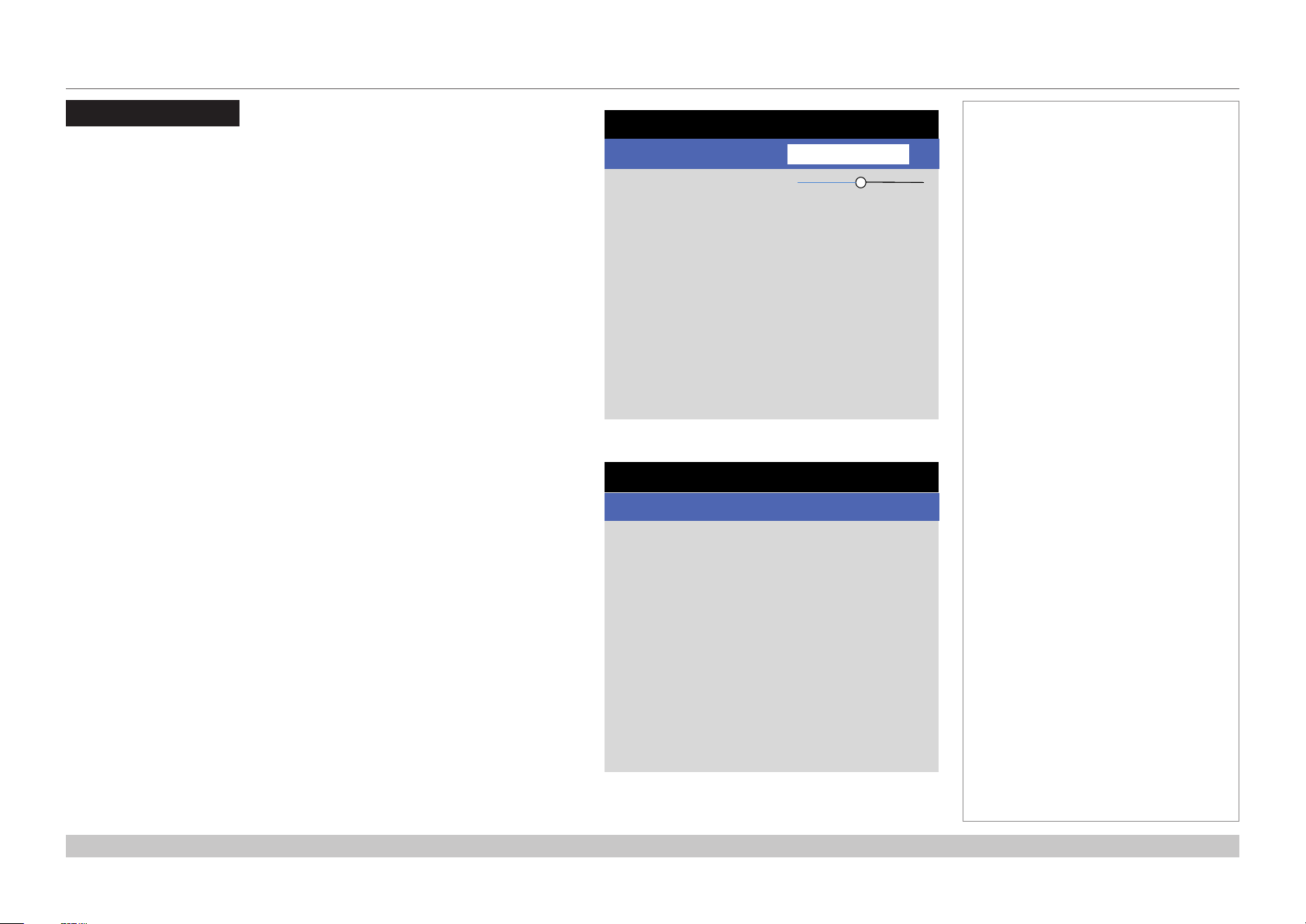
Image Menu
• Gamma SDR / HDR
Select to access Gamma controls..
• Brightness, Contrast, Saturation, Hue, Sharpness
Set the slider as required to improve the quality of the image.
• Gain and Lift
Select to access Gain and Lift controls.
Gamma SDR / HDR
The Gamma setting can improve contrast while maintaining good details for blacks
and whites.
If excess ambient light washes out the image and it is dicult to see details in dark
areas, lower the Gamma setting to compensate. This improves contrast while
maintaining good details for blacks. Conversely, if the image is washed out and
unnatural, with excessive detail in black areas, increase the setting.
Choose a de-gamma setting from AUTO, SDR (Standard Dynamic Range) or HDR
(High Dynamig Range)
For SDR Gamma, choose a de-gamma curve from 2.2 - 2.8
HDR (High Dynamic Range) is a new form of gamma developed to create more
realistic experience when viewing images delivered using this format, such as
scenes with bright sunlight. HDR is not device or installation independent. HDR
content will come with a recommended brightness regardless of screen size. For
best results as a guideline the following screens sizes are suggested.
HDR options should only be used with media players and sources equiped with
HDR and HDR content.
IMAGE
Gamma SDR / HDR >
Input
Brightness 100
Contrast 100
Saturation 100
Hue 100
Sharpness 100
Gain and Lift
HDMI 1
Gamma SDR / HDR
Select >
Input
SDR Gamma
HDR EOTF
HLG Gamma
HDR Range
Knee
Knee Point 50
Knee Slope 50
Knee Smooth 50
Auto
2.2
PQ
1.2
Full
On
HDMI 1
Notes
>
>
>
>
>
>
Operating Guide
Rev A October 2018
page 32
Page 41

Digital Projection INSIGHT Laser 8K Series
IMAGE MENU
Gamma SDR / HDR continued
For HDR Gamma, choose a HDR EOTF of HLG or PQ
Perceptual Quantizer (PQ) is the digitizing concept for capture and display and
provides metadata to enable the display to understand the coding of the content.
Hybrid Log Gamma (HLG) is a broadcast version of HDR or live TV and events
For HDR-HLG Gamma, choose a de-gamma curve from 1.0 - 1.5 and choose the
HDR Range of Auto, Narrow or Full
• Knee
Select to turn Knee on or o for HDR Gamma
• Knee Point, Knee Slope, Knee Smooth
Set the slider as required to improve the brightness of the image when using
HDR Gamma.
Gain and Lift
• Red Lift, Green Lift, Blue Lift
Set the slider as required to adjust the black levels of individual colors.
• Red Gain, Green Gain, Blue Gain
Set the slider as required to adjust the brightness of the scale for individual
colors.
• Reet
Select to reset the Gain and Lift settings.
Gamma SDR / HDR
Select >
Input
SDR Gamma
HDR EOTF
HLG Gamma
HDR Range
Knee
Knee Point 50
Knee Slope 50
Knee Smooth 50
Auto
2.2
PQ
1.2
Full
On
HDMI 1
Gain and Lift
Red Lift 100
Input
Green Lift 100
Blue Lift 100
Red Gain 100
Green Gain 100
Blue Gain 100
Reset
HDMI 1
Execute >
Notes
>
>
>
>
>
Operating Guide
Rev A October 2018
page 33
Page 42
Digital Projection INSIGHT Laser 8K Series
COLOR MENU
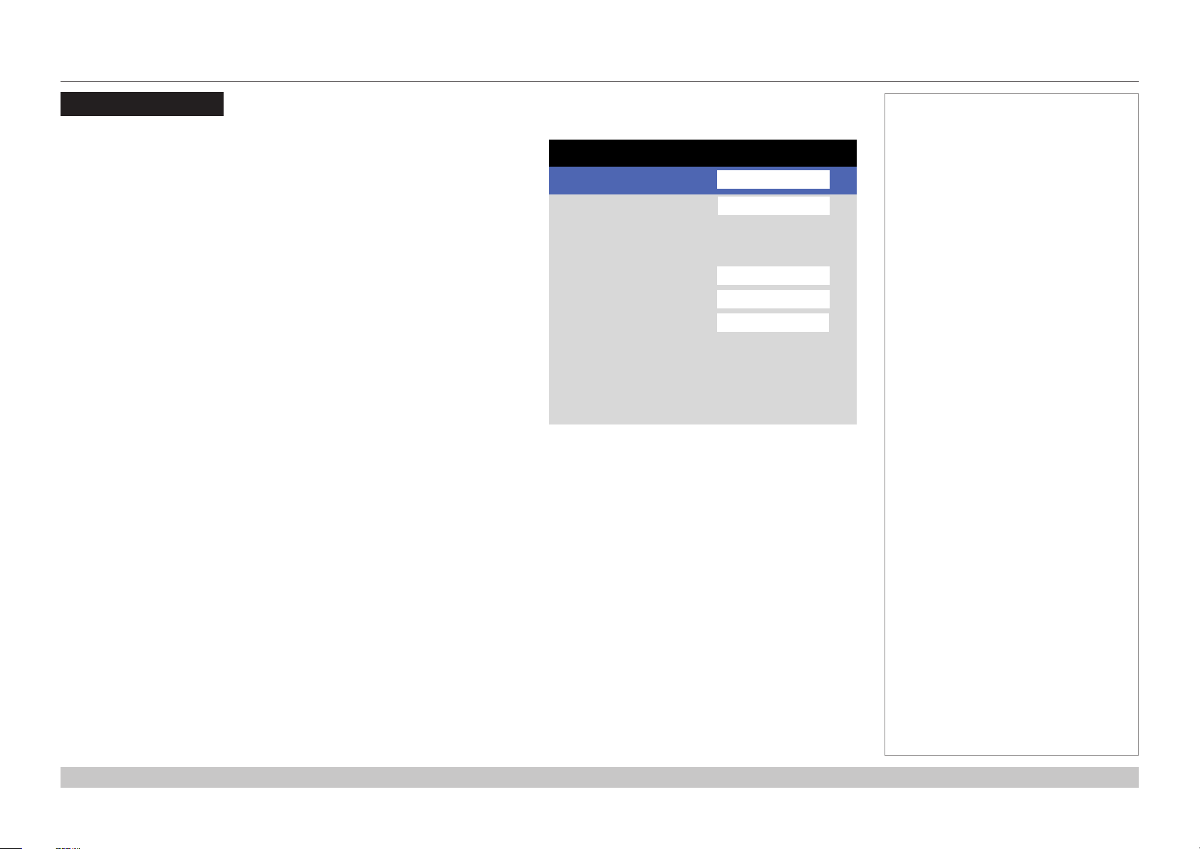
Color Menu
• Color Mode
Select the color mode setting. Choose from ColorMax or Manual Color.
• Color Max and Color Temperature
These features are enabled for ColorMax
• Manual Color Matching
This feature is enabled for Manual Color
ColorMax
1. Set Color Mode to ColorMax
2. Set the ColorMax setting. Choose from Rec.709, Rec.2020, DCI-P3, Native,
User1, User2.
User 1 and User 2 are user-dened color gamuts set via the Setup >
ColorMax menu
3. Set the Color Temperature. Choose a value between 3200K (warmer) and
9300K (cooler), or Native (no correction).
Manual Color Matching
1. Set Color Mode to Manual Color.
2. Access the Manual Color Matching submenu.
Here you can do the following:
• Adjust Hue, Saturation and Gain settings for each individual color to
improve the color balance of the projected image.
• Adjust white balance RGB values.
• Reset all values.
COLOR
Color Mode >
Input
Color Max
Color Temperature
Manual Color Matching
Color Max
HDMI 1
Rec.709
6500X
Manual Color Matching
Red >
Input
Green
Blue
Cyan
Magenta
Yellow
White Balance
Reset
HDMI 1
Execute >
Notes
>
>
>
>
>
>
>
>
>
Operating Guide
Rev A October 2018
page 34
Page 43
Digital Projection INSIGHT Laser 8K Series
COLOR MENU
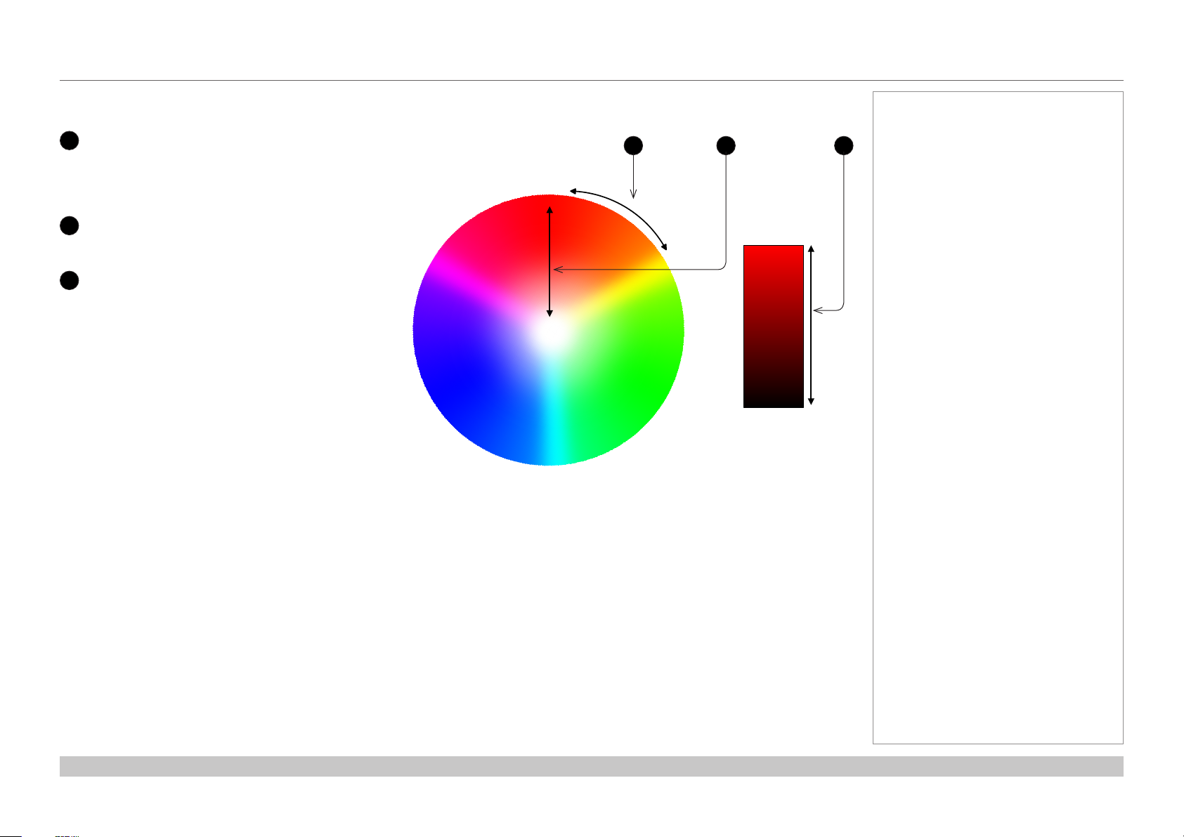
Color matching parameters explained
The levels of hue, saturation and gain in the Manual Color Matching menu change the color values in the following ways:
1
Hue
Species the position of each color
21 3
(red, yellow, green, cyan, blue and
magenta) relative to its neighboring
RED
colors.
2
Saturation
Species the level of white in each
3
Gain
color (i.e. how “pale” each color is).
MAGENTA
YELLOW
Controls the amount of light that goes
into each color, i.e. the lowest gain
would produce black.
WHITE
GREENBLUE
CYAN
Notes
RED
BLACK
Operating Guide
Rev A October 2018
page 35
Page 44

Digital Projection INSIGHT Laser 8K Series
ALIGNMENT MENU
Alignment Menu
Blanking
Use this feature to:
• t an odd-sized screen;
• cut o timecode dots in the top line of a picture;
• cut o subtitles, etc.
Select the edge you wish to blank and use the LEFT and RIGHT arrow
buttons to determine the amount of correction.
Use the Reset command to restore blanked edges
ALIGNMENT
Blanking >
Input HDMI 1
Blanking
Top 100
Input
Bottom 100
Left 100
Right 100
Reset
HDMI 1
Execute >
Notes
Operating Guide
Rev A October 2018
page 36
Page 45
Digital Projection INSIGHT Laser 8K Series
LASER MENU
Laser Menu
• Power Mode
Select this submenu to access the power mode setting.
• Power Level
This feature is activated for Custom Power Mode
Use the slider to set a value between 30 and 100%.
Power Mode
• Eco will automatically set the laser power to 80%.
• Normal will set the power to 100%.
• Select Custom to adjust the power manually.
LASER
Power Mode >
Input HDMI 1
Power Level 50
Custom
Power Mode
Eco
Auto
Normal
Custom
Notes
Operating Guide
Rev A October 2018
page 37
Page 46
Digital Projection INSIGHT Laser 8K Series
SETUP MENU
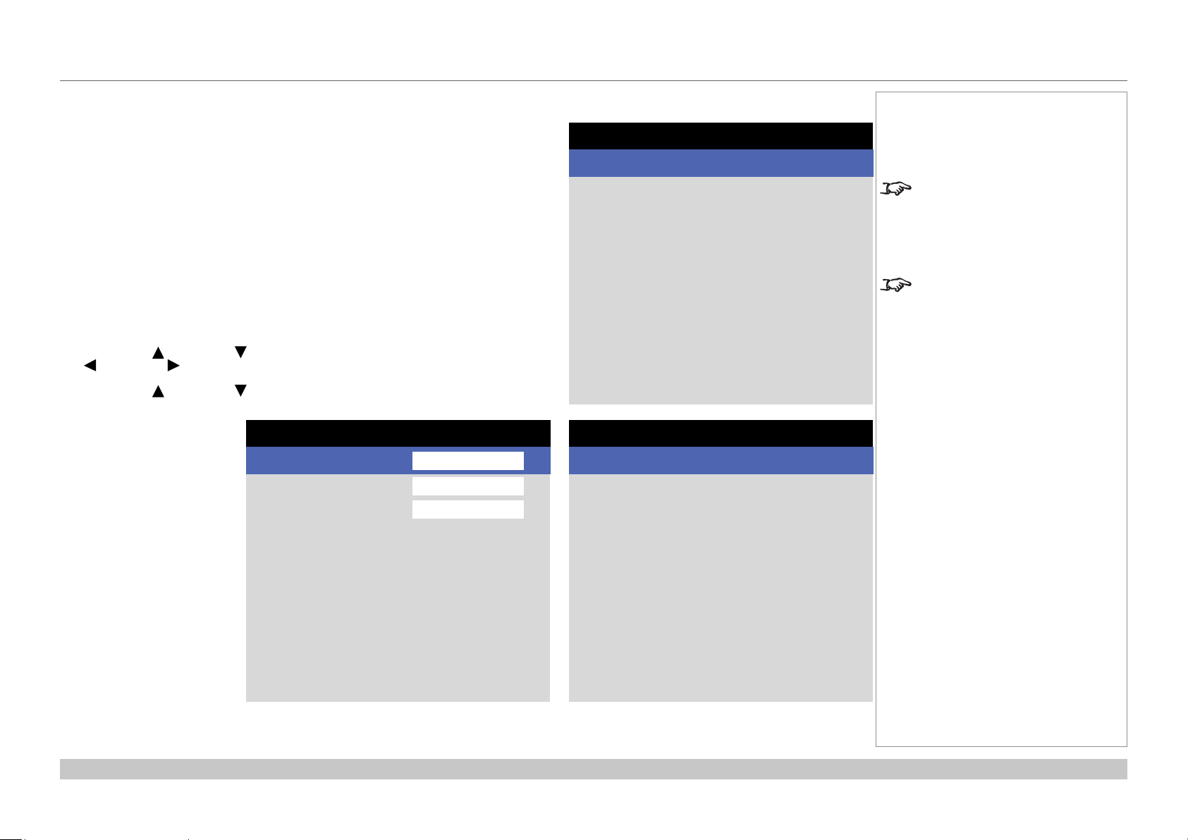
Setup menu
• Projection Mode
Choose from Front Desktop, Front Ceiling, Rear Desktop, and Rear
Ceiling
• High Altitude
Choose from On, or Auto.
• ColorMax
Set up user-dened color gamut values.
• Power Management
Choose from Auto Power Off and Auto Power On.
• Blank Screen
Choose from Logo, Black, Blue and White.
• Startup Logo
Set this to On if you want the DP logo to show when the projector is rst
switched on.
Projection Mode >
Input
High Altitude
ColorMax
Power Management
Blank Screen
Startup Logo
Remote Control
OSD Settings
Memory
• Remote Control
Set this to On o activate the remote control.
• OSD Settings
Access this submenu to adjust the appearance and position of the on-screen display.
• Memory
Access this submenu to save up to four presets containing custom combinations of image settings, or to recall a saved preset.
SETUP
Front Desktop
Auto
Logo
On
On
Notes
HDMI 1
>
>
>
>
>
>
Operating Guide
Rev A October 2018
page 38
Page 47
Digital Projection INSIGHT Laser 8K Series
SETUP MENU
Setup menu continued from previous page
ColorMax
ColorMax permits seven point color matching of red, green, blue, yellow, cyan,
magenta and white.
You can enter your own gamut values here, or edit values you have imported using the
Projector Controller software.
Dening your own colorspace with individual x and y coordinates for each color
enables you to match not only the whites but each individual color as well.
Highlight the submenu you wish to open and press ENTER/OK to conrm your choice.
Measured Data / Target Data
1. Use the UP and DOWN arrow buttons to highlight a color, then use the LEFT
and RIGHT arrow buttons to navigate to the x or y coordinate.
2. Use the UP and DOWN arrow buttons to increase and decrease the value,
respectively.
3. Exit edit mode:
• press ENTER/OK, if
you want to save the
edited values.
• press EXIT, if you
do not wish to save
the edited values
4. If necessary, highlight
another color and repeat
the procedure.
Color Mode >
Input
Color Max
Color Temperature
Manual Color Matching
COLOR
Color Max
Rec.709
6500X
HDMI 1
>
>
>
ColorMax
Measured Data >
Input HDMI 1
Target Data – User 1
Target Data – User 2
Target Data – User 1
Red x: 0.640 y: 0.390
Input HDMI 1
Green x: 0.300 y: 0.600
Blue x: 0.015 y: 0.060
Yellow x: 0.419 y: 0.505
Cyan x: 0.225 y: 0.329
Magenta x: 0.321 y: 0.154
White x: 0.285 y: 0.302
Notes
>
>
The Projector Controller software
is available for download from the
Digital Projection website, free of
charge.
This tool is best used in conjunction
with a specialized light meter (a
photo spectrometer) to measure
color parameters within a particular
installation. However, the preloaded
generic factory default data set
is designed to give more than
satisfactory results.
Operating Guide
Rev A October 2018
page 39
Page 48

Digital Projection INSIGHT Laser 8K Series
SETUP MENU
Setup menu continued from previous page
Power On/Off
• Auto Power Off
Set this to On if you want the projector to go into STANDBY mode when no
input source is detected for 20 minutes.
• Auto Power On
Set this to On if you want the projector to start up immediately when the mains
is connected.
Set this to Off if you want the projector to go into STANDBY mode when
the mains is connected. In this case, the projector will not start up until the
POWER button is pressed on the control panel or the ON button is pressed on
the remote control.
OSD Settings
• Language sets the OSD language.
• Menu Position determines where the OSD should appear on the screen
when activated.
• Menu Transparency sets OSD transparency between 0% (no transparency),
25%, 50% and 75%.
• Time Out determines how long the OSD should remain on screen if no
buttons are pressed. Choose Always On to disable this feature.
• Message Box determines whether projector status messages should appear
on the screen
Power Management
Auto Power Off >
Input HDMI 1
Auto Power On
Off
On
OSD Settings
Language >
Input
Menu Position
Menu Transperency
Time Out
Message Box
English
HDMI 1
Center
0%
Always On
On
Notes
>
>
>
>
>
Operating Guide
Rev A October 2018
page 40
Page 49

Digital Projection INSIGHT Laser 8K Series
SETUP MENU
Setup menu continued from previous page
Memory
The current image settings can be saved as a preset, which you can recall later.
The default settings can be recalled at any time as well.
Up to four custom presets can be stored for each input.
The following settings are saved in a preset:
• From the Image menu — Smooth Picture, Gamma, Brightness, Contrast,
Saturation, Hue, Sharpness
• From the Color menu — Color Space, Color Mode, ColorMax,
Color Temperature, RGB Lift and RGB Gain
To recall a saved preset:
• Select Recall Memory and press ENTER/OK, then select a preset from
Preset A to Preset D. Select Default to load factory default values.
To save a preset:
• Select Save Memory and press ENTER/OK, then choose from Preset A,
Preset B, Preset C and Preset D..
Memory
Recall Memory >
Input HDMI 1
Save Memory
Default
Preset A
Notes
>
Operating Guide
Rev A October 2018
page 41
Page 50

Digital Projection INSIGHT Laser 8K Series
NETWORK MENU
Network Menu
• DHCP, IP, Subnet Mask, Gateway, DNS
Set DHCP to On if the IP address is to be assigned by a DHCP server, or Off
if it is to be set here.
If DHCP is On, it will not be possible to edit IP Address, Subnet Mask,
Gateway or DNS.
If DHCP is set to Off, edit IP Address, Subnet Mask, Gateway and DNS as
required.
• MAC
This eld is read-only.
• AMX
Switch on or o.
NETWORK
DHCP >
Input
IP Address
Subnet Mask
Gateway
DNS Server
MAC Address
Off
HDMI 1
192.168.0.100 >
255.255.255.0 >
192.168.0.254 >
192.168.0.1 >
CO:AB:00:01:00:00 >
Notes
Operating Guide
Rev A October 2018
page 42
Page 51

Digital Projection INSIGHT Laser 8K Series
INFORMATION MENU
Information Menu
This menu gives information about laser operating times, network conguration,
OSD software and hardware, system information such as model name and
rmware version, and video conguration.
Open a submenu to see related information.
INFORMATION
Model Name Insight 8k
Input
Serial Number
Software Version 1
Software Version 2
Software Version 3
Laser Hours
Input Status
Thermal Status
System Status
Factory Reset
PE59_S17_LD-4-2-2_MM
HDMI 1
M00.77-i00.33-s00.26
B08.04-fr06.03-fg06.03
Execute >
Notes
9
>
>
>
Operating Guide
Rev A October 2018
page 43
Page 52

Digital Projection INSIGHT Laser 8K Series
INFORMATION MENU
Input Status
Thermal Status
Input Status
Format
Channel S tatus
Ch1
…………..…………………………………………………………
Ch2
…………..…………………………………………………………
Ch3
…………..…………………………………………………………
Ch4
…………..…………………………………………………………
Ch5
…………..…………………………………………………………
Ch6
…………..…………………………………………………………
Ch7
…………..…………………………………………………………
Ch8
…………..…………………………………………………………
Ch9
…………..…………………………………………………………
Ch10
…………..…………………………………………………………
Ch11
…………..…………………………………………………………
Ch12
…………..…………………………………………………………
Ch13
…………..…………………………………………………………
Ch14
…………..…………………………………………………………
Ch15
…………..…………………………………………………………
Ch16
3G-SDI Level A / HD(1920x1080)
60p / YCbCr4:2:2 / 10 bit
3G-SDI Level A / PID:89, CB, 00, 01
Thermal Status
Inlet Temp
DMD Temp
LD Temp
Fan 1 – 4 Speed
Fan 5 – 8 Speed
Fan 9 – 12 Speed
Fan 13 – 16 Speed
Fan 17 – 20 Speed
Fan 21 – 24 Speed
Fan 25 – 28 Speed
Fan 29 – 32 Speed
Water Pump
42/44/43/42/38/38 – 41/43/43/42/38/38
2857/2997/4915/4915
3233/3150/3233/3231
2997/3150/3233/3840
2730/2671/0/3233
3072/4096/4096/0
3072/4096/4096/0
3150/3172/3614/3614
3963/4096/3233/3150
3180/3260/3220/3240/0
Notes
No Signal
No Signal
No Signal
No Signal
No Signal
No Signal
No Signal
No Signal
No Signal
No Signal
No Signal
No Signal
No Signal
No Signal
No Signal
Notes
196
46
Operating Guide
Rev A October 2018
page 44
Page 53

Digital Projection INSIGHT Laser 8K Series
INFORMATION MENU
System Status
Factory Reset
System Status
Wheel Speed
Atmospheric Pressure
Altitude Mode
Laser Power
Filter Hours
Notes
0/0
0kPs
Auto
100
9
Operating Guide
Factory Reset
WARNING
The Projector Will Return to Factory Setting
Press OK to confirm
Press EXIT to cancel
Rev A October 2018
page 45
Page 54

INSIGHT Laser 8K Series
High Brightness Digital Video Projector
4
REFERENCE GUIDE
Rev A October 2018
Page 55

Digital Projection INSIGHT Laser 8K Series
IN THIS GUIDE
IN THIS GUIDE
Choosing A Lens ................................................................................................ 48
Throw Ratios for 8K or 4K-UHD ...............................................................................48
Throw Ratios for 4K ..................................................................................................48
Screen Requirements ...................................................................................... 49
Fitting the image to the DMD™ ................................................................................49
Positioning The Image .................................................................................... 50
Maximumosetrange ..............................................................................................52
Oset for 8K or 4K-UHD .................................................................................................52
Oset for 4K ....................................................................................................................52
Aspect Ratios Explained ................................................................................ 53
Appendix A: Lens Part Numbers .................................................................. 54
Lens Parts for 8K or 4K-UHD ...................................................................................54
Lens Parts for 4K ......................................................................................................55
Appendix C: Supported Signal Input Modes ............................................ 56
Appendix D: Wiring Details ........................................................................... 57
Signal inputs ..............................................................................................................57
3G-SDI or 12G-SDI In, 3G-SDI or 12G-SDI Out .............................................................57
Control connections .................................................................................................57
LAN .................................................................................................................................57
RS232 .............................................................................................................................57
Appendix E: Glossary Of Terms ................................................................... 58
Reference Guide
Rev A October 2018
Page 56

Digital Projection INSIGHT Laser 8K Series
CHOOSING A LENS
Choosing A Lens
A number of lenses are available. Which lens you choose depends on the screen size, image aspect ratio, throw distance and light output.
Throw Ratios for 8K or 4K-UHD
The following table shows all available lenses in order of their throw ratios when using 8K (7680 x 4320) or 4K-UHD (3840 x 2160):
Throw ratios Lens extension (±2%) Throw distance range
1.21 - 1.83 : 1 zoom lens 225 mm (8.9 in) 2.5 m - 40+ m (8.2 ft - 130+ ft) at 1.13:1
0.5 m - 40+ m (1.6 ft - 130+ ft) at 1.72:1
1.76 - 2.77 : 1 zoom lens 195 mm (7.7 in) 3.5 m - 40+ m (11.5 ft - 130+ ft) at 1.65:1
1.0 m - 40+ m (3.3 ft - 130+ ft) at 2.60:1
2.70 - 5.31 : 1 zoom lens 195 mm (7.7 in) 1.5 m - 40+ m (4.9 ft - 130+ ft) at 2.53:1
4.5 m - 40+ m (14.8 ft - 130+ ft) at 4.98:1
Throw Ratios for 4K
The following table shows all available lenses in order of their throw ratios when using 4K (4096 x 2160):
Throw ratios Lens extension (±2%) Throw distance range
1.13 - 1.72 : 1 zoom lens 225 mm (8.9 in) 2.5 m - 40+ m (8.2 ft - 130+ ft) at 1.13:1
0.5 m - 40+ m (1.6 ft - 130+ ft) at 1.72:1
Notes
INSIGHT 8K zoom lenses are
capable of covering throw distances
greater than forty metres.
The minimum throw of the zoom
lenses changes depending on the
throw ratio used.
For information about individual lens
part numbers, see Appendix A at
the end of this document.
1.65 - 2.60 : 1 zoom lens 195 mm (7.7 in) 3.5 m - 40+ m (11.5 ft - 130+ ft) at 1.65:1
1.0 m - 40+ m (3.3 ft - 130+ ft) at 2.60:1
2.53 - 4.98 : 1 zoom lens 195 mm (7.7 in) 1.5 m - 40+ m (4.9 ft - 130+ ft) at 2.53:1
4.5 m - 40+ m (14.8 ft - 130+ ft) at 4.98:1
Reference Guide
Rev A October 2018
page 48
Page 57

Digital Projection INSIGHT Laser 8K Series
SCREEN REQUIREMENTS
Screen Requirements
Fitting the image to the DMD™
The projector supports 8K, 4K and Ultra HD formats and is able to achieve 2K and 1080p via frame doubling.
2K and frame doubled 1080p will not utilize the full width of the DMD™, resulting in pillarboxing, as shown in the illustration.
true 4K (also pixel doubled 2K) = 4096 pixels
8K (also pixel doubled 4K) = 7680 pixels
UHD (also pixel doubled 1080p) = 3840 pixels
Notes
Reference Guide
true 8K ( also pixel doubled 4K, 2160p) = 4320 pixels
true 4K, UHD ( also pixel doubled 2K, 1080p) = 2160 pixels
Rev A October 2018
page 49
Page 58
Digital Projection INSIGHT Laser 8K Series
POSITIONING THE IMAGE
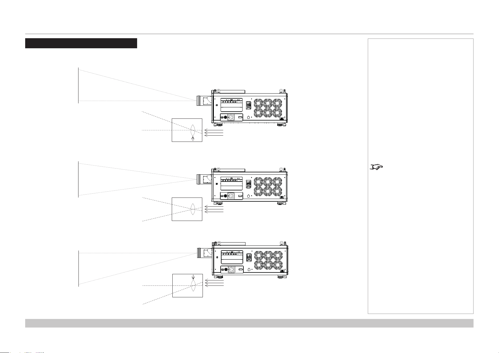
Positioning The Image
The normal position for the projector is at the centre of the screen. However, you can set the projector above or below the centre, or to one side,
and adjust the image using the Lens shift feature (known as rising and falling front) to maintain a geometrically correct image.
Shifting the lens up (rising front)
Notes
Whenever possible, position the
projector so that the lens is centered
for the highest quality image.
Reference Guide
Centered lens
Shifting the lens down (falling front)
Rev A October 2018
page 50
Page 59

Digital Projection INSIGHT Laser 8K Series
Any single adjustment outside the ranges specied on the following page may result in an unacceptable level of distortion, particularly at the
corners of the image, due to the image passing through the periphery of the lens optics.
If the lens is to be shifted in two directions combined, the maximum range without distortion will be somewhat less, as can be seen in the
illustrations below.
POSITIONING THE IMAGE
Notes
For more information on shifting
the lens, see Lens control in the
Operating Guide.
Reference Guide
Full horizontal or vertical shift Combined shift is reduced
Rev A October 2018
page 51
Page 60

Digital Projection INSIGHT Laser 8K Series
POSITIONING THE IMAGE
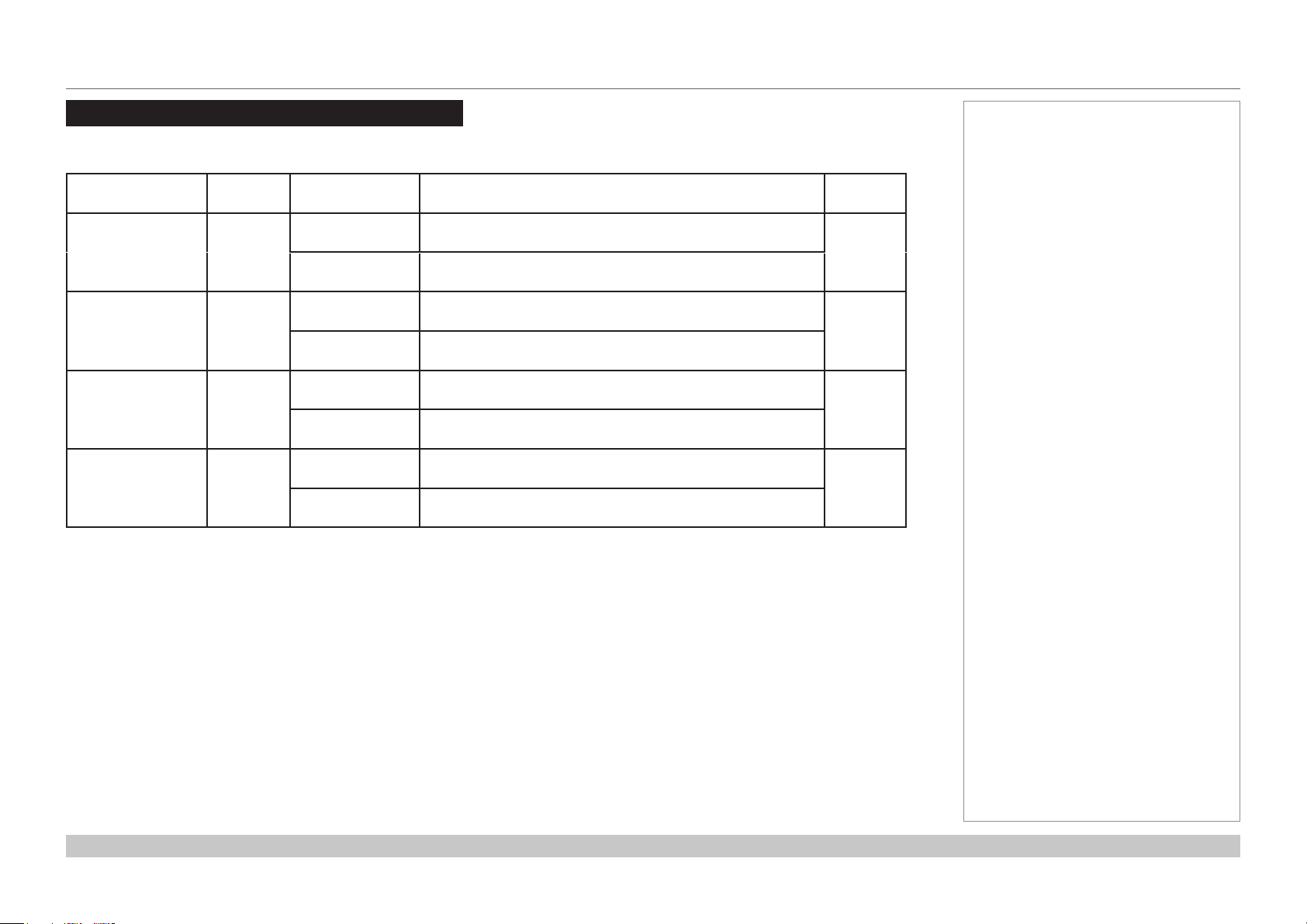
Maximum offset range
The maximum oset range available is dependent on which lens and resolution is used. Shifting the lens beyond its undistorted limits may be
physically possible, however you may experience excessive vignetting or distortion.
Offset for 8K or 4K-UHD
vertical
(frame)
1.21 - 1.83 : 1 zoom at 1.21:1 0.340 U
0.190 D
at 1.83:1 0.500 U
0.190 D
1.76 - 2.77 : 1 zoom at 1.76:1 0.400 U
0.210 D
at 2.77:1 0.500 U
0.200 D
2.70 - 5.31 :1 zoom at 2.70:1 0.375 U
0.200 D
at 5.31:1 0.500 U
0.195 D
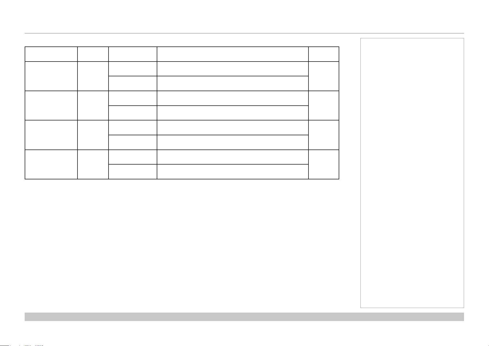
Offset for 4K
vertical
(frame)
horizontal
(frame)
0.085 L
0.100 R
0.150 L
0.180 R
0.130 L
0.130 R
0.150 L
0.190 R
0.130 L
0.130 R
0.165 L
0.165 R
horizontal
(frame)
Notes
For more information on shifting
the lens, see Lens control in the
Operating Guide.
1.13 - 1.72 : 1 zoom at 1.13:1 0.340 U
0.190 D
at 1.72:1 0.500 U
0.190 D
1.65 - 2.60 : 1 zoom at 1.65:1 0.400 U
0.210 D
at 2.60:1 0.500 U
0.200 D
2.53-4.98 :1 zoom at 2.53:1 0.375 U
0.200 D
at 4.98:1 0.500 U
0.195 D
Reference Guide
0.085 L
0.100 R
0.150 L
0.180 R
0.130 L
0.130 R
0.150 L
0.190 R
0.130 L
0.130 R
0.165 L
0.165 R
Rev A October 2018
page 52
Page 61

Digital Projection INSIGHT Laser 8K Series
ASPECT RATIOS EXPLAINED
Aspect Ratios Explained
The appearance of a projected image on the screen depends on:
• the DMD™ resolution, which is 4K with a 4096 x 2160 resolution, corresponding to an aspect ratio of approximately 1.9:1.
• the aspect ratio of the input signal, which is 1.9:1 for 4K and 2K images, or 1.78:1 for 8K, 4K-UHD or 1080p images.
The 4K and 2K resolutions have a slightly wider aspect ratio. 8K, 4K-UHD and scaled 1080p do not ll the width of the DMD™, so they
appear centered, with pillarboxing at the sides, as shown in the illustration.
Notes
Reference Guide
Pillarboxing on UHD and 1080p images
Rev A October 2018
page 53
Page 62
Digital Projection INSIGHT Laser 8K Series
APPENDIX A: LENS PART NUMBERS
Appendix A: Lens Part Numbers
Lens Parts for 8K or 4K-UHD
Lens Part No. Focus Range Lens Shift
1.21 - 1.83:1 zoom 115-627
1.76 - 2.77:1 zoom 115-630
2.70 - 5.31:1 zoom
115-632
(EU-EA)
2.70 - 5.31:1 zoom
115-632
with Hood (USA)
At 1.13:1 zoom:
2.5 m - 100+ m
At 1.72:1 zoom:
0.5 m - 100+ m
At 1.65:1 zoom:
3.5 m - 100+ m
At 2.60:1 zoom:
1.0 m - 100+ m
At 2.53:1 zoom:
1.5 m - 100+ m
At 4.98:1 zoom:
4.5 m - 100+ m
At 2.53:1 zoom:
1.5 m - 100+ m
At 4.98:1 zoom:
4.5 m - 100+ m
At 1.13:1 zoom:
Vert: 0.340 (U) 0.190 (D) frame, Hor: 0.09 (L) 0.09 (R) frame
At 1.72:1 zoom:
Vert: 0.500 (U) 0.190 (D) frame, Hor: 0.16 (L) 0.16 (R) frame
At 1.65:1 zoom:
Vert: 0.400 (U) 0.200 (D) frame, Hor: 0.13 (L) 0.13 (R) frame
At 2.60:1 zoom:
Vert: 0.500 (U) 0.200 (D) frame, Hor: 0.17 (L) 0.17 (R) frame
At 2.53:1 zoom:
Vert: 0.375 (U) 0.200 (D) frame, Hor: 0.13 (L) 0.13 (R) frame
At 4.98:1 zoom:
Vert: 0.500 (U) 0.195 (D) frame, Hor: 0.16 (L) 0.16 (R) frame
At 2.53:1 zoom:
Vert: 0.375 (U) 0.200 (D) frame, Hor: 0.13 (L) 0.13 (R) frame
At 4.98:1 zoom:
Vert: 0.500 (U) 0.195 (D) frame, Hor: 0.16 (L) 0.16 (R) frame
Notes
Lens
extension
225 mm
195 mm
195 mm
195 mm
Reference Guide
Rev A October 2018
page 54
Page 63
Digital Projection INSIGHT Laser 8K Series
APPENDIX A: LENS PART NUMBERS
Lens Parts for 4K
Lens Part No. Focus Range Lens Shift
1.13 - 1.72:1 zoom 115-627
1.65 - 2.60:1 zoom 115-630
2.53 - 4.98:1 zoom
115-632
(EU-EA)
2.53 - 4.98:1 zoom
119-662
with Hood (USA)
At 1.13:1 zoom:
2.5 m - 100+ m
At 1.72:1 zoom:
0.5 m - 100+ m
At 1.65:1 zoom:
3.5 m - 100+ m
At 2.60:1 zoom:
1.0 m - 100+ m
At 2.53:1 zoom:
1.5 m - 100+ m
At 4.98:1 zoom:
4.5 m - 100+ m
At 2.53:1 zoom:
1.5 m - 100+ m
At 4.98:1 zoom:
4.5 m - 100+ m
At 1.13:1 zoom:
Vert: 0.340 (U) 0.190 (D) frame, Hor: 0.09 (L) 0.09 (R) frame
At 1.72:1 zoom:
Vert: 0.500 (U) 0.190 (D) frame, Hor: 0.16 (L) 0.16 (R) frame
At 1.65:1 zoom:
Vert: 0.400 (U) 0.200 (D) frame, Hor: 0.13 (L) 0.13 (R) frame
At 2.60:1 zoom:
Vert: 0.500 (U) 0.200 (D) frame, Hor: 0.17 (L) 0.17 (R) frame
At 2.53:1 zoom:
Vert: 0.375 (U) 0.200 (D) frame, Hor: 0.13 (L) 0.13 (R) frame
At 4.98:1 zoom:
Vert: 0.500 (U) 0.195 (D) frame, Hor: 0.16 (L) 0.16 (R) frame
At 2.53:1 zoom:
Vert: 0.375 (U) 0.200 (D) frame, Hor: 0.13 (L) 0.13 (R) frame
At 4.98:1 zoom:
Vert: 0.500 (U) 0.195 (D) frame, Hor: 0.16 (L) 0.16 (R) frame
Notes
Lens
extension
225 mm
195 mm
195 mm
195 mm
Reference Guide
Rev A October 2018
page 55
Page 64

Digital Projection INSIGHT Laser 8K Series
APPENDIX C: SUPPORTED SIGNAL INPUT MODES
Appendix C: Supported Signal Input Modes
Input Timing
Format No.
3G-SDI
8K(7680 x 4320) YCbCr 4:2:2 10bit 59.94p 0x82 V(x16, 16div) V(x4, 2SI/SQD)
8K(7680 x 4320) YCbCr 4:2:2 10bit 60p 0x83 V(x16, 16div) V(x4, 2SI/SQD)
8K(7680 x 4320) YCbCr 4:2:2 10bit 50p 0x84 V(x16, tile) V(x4, 2SI/SQD)
8K(7680 x 4320) YCbCr 4:2:2 10bit 25p 0x86 V(4*(x2(LevB-DS), SQD)) V(x2(DL), 2SI)
8K(7680 x 4320) YCbCr 4:2:2 10bit 23.97p 0x87 V(4*(x2(LevB-DS), SQD)) V(x2(DL), 2SI)
8K(7680 x 4320) YCbCr 4:2:2 10bit 24p 0x88 V(4*(x2(LevB-DS), SQD)) V(x2(DL), 2SI)
8K(7680 x 4320) YCbCr 4:2:2 10bit 29.97p 0x89 V(4*(x2(LevB-DS), SQD)) V(x2(DL), 2SI)
8K(7680 x 4320) YCbCr 4:2:2 10bit 30p 0x8A V(4*(x2(LevB-DS), SQD)) V(x2(DL), 2SI)
4K(3840 x 2160) YCbCr 4:2:2 10bit 59.94p 0x94 V(x4, 2SI/SQD) V(x1, 2SI)
4K(3840 x 2160) YCbCr 4:2:2 10bit 60p 0x95 V(x4, 2SI/SQD) V(x1, 2SI)
4K(3840 x 2160) YCbCr 4:2:2 10bit 50p 0x96 V(x4, 2SI/SQD) V(x1, 2SI)
4K(4096 x 2160) YCbCr 4:2:2 10bit 59.94p 0xA4 V(x4, 2SI/SQD) V(x1, 2SI)
4K(4096 x 2160) YCbCr 4:2:2 10bit 60p 0xA5 V(x4, 2SI/SQD) V(x1, 2SI)
4K(4096 x 2160) YCbCr 4:2:2 10bit 50p 0xA6 V(x4, 2SI/SQD) V(x1, 2SI)
HD(1920 x 1080) YCbCr 4:2:2 10bit 59.94p 0xB0 V(x1) up scaling to (4K)
HD(1920 x 1080) YCbCr 4:2:2 10bit 60p 0xB1 V(x1) up scaling to (4K)
HD(1920 x 1080) YCbCr 4:2:2 10bit 50p 0xB2 V(x1) up scaling to (4K)
12G-SDI
Note
Notes
24, 30, 50 and 60 Hz are nominal:
the projector also accepts at least
23.98, 25, 48 and 59.94 Hz.
Reference Guide
Rev A October 2018
page 56
Page 65

Digital Projection INSIGHT Laser 8K Series
APPENDIX D: WIRING DETAILS
Appendix D: Wiring Details
Signal inputs
3G-SDI or 12G-SDI In, 3G-SDI or 12G-SDI Out
75 ohm BNC
Control connections
LAN
RJ45 socket
RS232
9 way D-type connector
Pin
RS-232C
No.
Signal Name
1 CD Carrier detection Not used (N.C.)
2 RXD Reception data Data transmission to an external device
3 TXD Transmission data Data reception from an external device
4 DTR Data Terminal ready
5 GND Signal GND Signal GND
6 DSR Data set ready (Note) Connection to 4 pins
7 RTS Transmission request SYSTEM: Hi-Z (Not used)
8 CTS Transmission available SYSTEM: Fixed at -6.5 V (Not used)
9 RI Ring indicator Not used (N.C.)
Functions as RS-232C Projector Connector Operation
Connection to 6 pins
(Note)
CINEMA: Hi-Z (Used)
CINEMA: ±10.5 V (Used: Depends on
communication status)
3G-SDI connector
Update port
RS232:
pin view of female connector
Notes
3G-SDI and 12G-SDI signals are
very high speed digital signals which
require better quality coaxial cable
than conventional analogue video.
The data rate is 3 Gigabits per
second.
In choosing cable length and
connectors for any installation the
frequency response loss in decibels
should be proportional to √f, from 1
MHz, to 3 GHz.
Only one remote connection (RS232
or LAN) should be used at any one
time.
Reference Guide
Rev A October 2018
page 57
Page 66

Digital Projection INSIGHT Laser 8K Series
APPENDIX E: GLOSSARY OF TERMS
Appendix E: Glossary Of Terms
Below is a general glossary of terms. Some terms may not be applicable to this projector.
1080p
An HDTV resolution which corresponds to 1920 x 1080 pixels (a widescreen aspect ratio of 16:9).
4K
A 4K resolution which corresponds to 4096 x 2160 pixels (a widescreen aspect ratio of 1.89:1).
4K-UHD
A 4K-UHD resolution which corresponds to 3840 x 2160 pixels (a widescreen aspect ratio of 16:9).
8K
A 8K resolution which corresponds to 7860 x 4320 pixels (a widescreen aspect ratio of 16:9).
3D active glasses
Wireless battery-powered glasses with LCD shutters. Synchronization information is communicated to the glasses by means of an infrared
(IR) or radio frequency (RF) emitter which is connected to the Sync Out terminal on the projector. IR or RF pulses are transmitted by the
emitter to signal when the left eye and right eye images are being displayed. The glasses incorporate a sensor which detects the emitter’s
signal and synchronises the left and right eye shutters with the projected image.
Notes
3D passive glasses
Passive glasses do not require a power source to work. Light with left-hand polarisation can pass through the left lens and light with righthand polarisation can pass through the right-hand lens. These glasses are used in conjunction with another device which polarizes the image,
such as a ZScreen.
Adjust lines
A pattern applied to the image where its edge is to be blended with another image. Adjust lines are used to position the projectors in the array
during the edge blend process.
Reference Guide
Rev A October 2018
page 58
Page 67

Digital Projection INSIGHT Laser 8K Series
APPENDIX E: GLOSSARY OF TERMS
Anamorphic lens
A special lens which, when used with the TheaterScope aspect ratio, allows watching 2.35:1 content packed in a 16:9 source.
Aperture
The opening of the lens that determines the angle through which light travels to come into focus.
Aspect ratio
The proportional relationship between the width and the height of the projected image. It is represented by two numbers separated by a colon,
indicating the ratio of image width and height respectively: for example, 16:9 or 2.35:1.
Not to be confused with resolution.
Blanking (projection)
The ability to intentionally turn o, that is, set to black, areas around the edges of the projected image. It is sometimes referred to as “curtains”
since it can be used to blank an area of image that literally falls on the curtains at the side of the screen in a movie theater. Usually no image
resizing or geometric correction takes place and the “blanked” part of the image is lost.
Not to be confused with horizontal and vertical blanking (video signal).
Blanking (video signal)
The section of the video signal where there is no active video data.
Not to be confused with blanking (projection).
Notes
Blend region
The area of the image that is to overlap with another image in an edge blend setup. Sometimes called overlapping region.
Brightness (electronic control)
A control which adds a xed intensity value to every pixel in the display, moving the entire range of displayed intensities up or down, and is
used to set the black point in the image (see Contrast).
Brightness (optical)
Describes how ‘bright’ an image that is projected onto a screen appears to an observer.
Reference Guide
Rev A October 2018
page 59
Page 68

Digital Projection INSIGHT Laser 8K Series
APPENDIX E: GLOSSARY OF TERMS
Color gamut
1
2
The spectrum of color available to be displayed.
Color temperature
The position along the black body curve on the chromaticity diagram,
normally quoted in Kelvin. It takes into account the preset values for color
balance in the service set-up to take up the variations in the prism. The
projector allows you to adjust this temperature (i.e. adjust the picture color
temperature).
Contrast (electronic control)
1
Throw distance
The adjustment of the white point of the image without aecting the black
point. This increases the intensity range of the displayed image.
2
Screen width
Contrast (optical)
The intensity dierence between the darkest and lightest areas of the screen.
Crop
Remove part of the projected image.
Alternatively, t an image into a frame with a dierent aspect ratio by removing part of the image. The image is resized so that either its
length or its width equals the length or width of the frame, while the other dimension has moved outside the frame; the excess area is then cut
out.
Notes
Dark time
The time inserted between frames when using 3D active glasses, to avoid ghosting caused by switching time between left and right eye.
DDC (Display Data Channel)
A communications link between the source and projector. DDC is used on the HDMI, DVI and VGA inputs. The link is used by the source to
read the EDID stored in the projector.
Reference Guide
Rev A October 2018
page 60
Page 69

Digital Projection INSIGHT Laser 8K Series
APPENDIX E: GLOSSARY OF TERMS
Deinterlacing
The process of converting interlaced video signals into progressive ones.
DHCP(DynamicHostCongurationProtocol)
A network protocol that is used to congure network devices so that they can communicate on an IP network, for example by allocating an IP
address.
DMD™ (Digital Micromirror Device™)
The optical tool that transforms the electronic signal from the input source into an optical image projected on the screen. The DMD™ of a
projector has a xed resolution, which aects the aspect ratio of the projected image.
A Digital Micromirror Device™ (DMD™) consists of moving microscopic mirrors. Each mirror, which acts as a pixel, is suspended between
two posts by a thin torsion hinge. It can be tilted to produce either a bright or dark pixel.
Edge blend
A method of creating a combined image by blending the adjoining edges of two or more individual images.
Edge tear
An artifact observed in interlaced video where the screen appears to be split horizontally. Edge tears appear when the video feed is out of
sync with the refresh rate of the display device.
Notes
EDID(ExtendedDisplayIdenticationData)
Information stored in the projector that can be read by the source.
EDID is used on the HDMI, DVI and VGA inputs, allowing the source to automatically congure to the optimum display settings.
EDTV(EnhancedDenitionTelevision)
A progressive digital television system with a lower resolution than HDTV.
Reference Guide
Rev A October 2018
page 61
Page 70

Digital Projection INSIGHT Laser 8K Series
APPENDIX E: GLOSSARY OF TERMS
Field
In interlaced video, a part of the image frame that is scanned separately. A eld is a collection of either all the odd lines or all the even lines
within the frame.
Frame
One of the many still images displayed in a sequence to create a moving picture. A frame is made of horizontal lines of pixels. For example,
a 1920x1080 frame consists of 1080 lines, each containing 1920 pixels. In analog video frames are scanned one at a time (progressive
scanning) or split into fields for each eld to be scanned separately (interlaced video).
Frame rate
The number of frames shown per second (fps). In TV and video, a frame rate is the rate at which the display device scans the screen to
“draw” the frame.
Frame rate multiplication
To stop low frame rate 3D images from ickering, frame rate multiplication can be used, which increases the displayed frame rate by two or
three times.
Gamma
A nonlinear operation used to code and decode luminance. It originates from the Cathode Ray Tube technology used in legacy television
sets.
Notes
Ghosting
An artifact in 3D image viewing. Ghosting occurs when an image intended for one eye is partially seen by the other eye.
Ghosting can be removed by optimizing the dark time and sync delay.
HDCP (High-bandwidth Digital Content Protection)
An encryption scheme used to protect video content.
Reference Guide
Rev A October 2018
page 62
Page 71

Digital Projection INSIGHT Laser 8K Series
APPENDIX E: GLOSSARY OF TERMS
HDTV(HighDenitionTelevision)
A television system with a higher resolution than SDTV and EDTV. It can be transmitted in various formats, notably 1080p and 720p.
Hertz (Hz)
Cycles per second.
Horizontal Scan Rate
The rate at which the lines of the incoming signal are refreshed. The rate is set by the horizontal synchronization from the source and
measured in Hertz.
Hs + Vs
Horizontal and vertical synchronization.
Interlacing
A method of updating the image. The screen is divided in two fields, one containing every odd horizontal line, the other one containing the
even lines. The elds are then alternately updated. In analog TV interlacing was commonly used as a way of doubling the refresh rate without
consuming extra bandwidth.
Interleaving
The alternation between left and right eye images when displaying 3D.
Notes
LED (Light Emitting Diode)
An electronic component that emits light.
Letterboxing
Black margins at the top and bottom of the image. Letterboxing appears when a wider image is packed into a narrower frame without
changing the original aspect ratio.
Reference Guide
Rev A October 2018
page 63
Page 72

Digital Projection INSIGHT Laser 8K Series
APPENDIX E: GLOSSARY OF TERMS
Lumen
A photometric unit of radiant power. For projectors, it is normally used to specify the total amount of emitted visible light.
Noise
Electrical interference displayed on the screen.
Overlapping region
See blend region.
Pillarboxing
Black margins at the left and right of the image. Pillarboxing appears when a narrower image is packed into a wider frame without changing
the aspect ratio.
Pixel
Short for Picture Element. The most basic unit of an image. Pixels are arranged in lines and columns. Each pixel corresponds to a micromirror
within the DMD™; resolutions reect the number of pixels per line by the number of lines. For example, a 1080p projector contains 1080
lines, each consisting of 1920 pixels.
Pond of mirrors
Area around the periphery of the DMD™ containing inactive mirrors. The pond of mirrors may cause artifacts, for example during the edge
blending process.
Notes
Primary colors
Three colors any two of which cannot be mixed to produce the third. In additive color television systems the primary colors are red, green and
blue.
Progressive scanning
A method of updating the image in which the lines of each frame are drawn in a sequence, without interlacing.
Reference Guide
Rev A October 2018
page 64
Page 73

Digital Projection INSIGHT Laser 8K Series
APPENDIX E: GLOSSARY OF TERMS
Pulldown
The process of converting a 24 fps lm footage to a video frame rate (25 fps for PAL/SECAM, 30 fps for NTSC) by adding extra frames. DP
projectors automatically carry out reverse pulldown whenever possible.
Resolution
The number of pixels in an image, usually represented by the number of pixels per line and the number of lines (for example, 1920 x 1200).
RGB (Red, Green and Blue)
An uncompressed Component Video standard.
Scope
An aspect ratio of 2.35:1.
Smooth Picture
A feature that can display a higher resolution source than the native resolution of the projector without loosing any pixel data.
Synchronization
A timing signal used to coordinate an action.
Notes
Test pattern
A still image specially prepared for testing a projection system. It may contain various combinations of colors, lines and geometric shapes.
Throw distance
The distance between the screen and the projector.
Throw ratio
The ratio of the throw distance to the screen width.
Reference Guide
Rev A October 2018
page 65
Page 74

Digital Projection INSIGHT Laser 8K Series
APPENDIX E: GLOSSARY OF TERMS
TRC (Throw ratio correction)
A special number used in calculating throw distances and throw ratios when the image does not ll the width of the DMD™.
TRC is the ratio of the DMD™ aspect ratio to the image source aspect ratio:
DMD™ aspect ratio
TRC =
Source aspect ratio
TRC is only used in calculations if it is greater than 1.
Vertical Scan Rate
The rate at which the frames of the incoming signal are refreshed. The rate is set by the vertical synchronization from the source and
measured in Hertz.
Vignetting
Optical cropping of the image caused by the components in the projection lens. This can happen if too much oset is applied when
positioning the image using the lens mount.
ZScreen
A special kind of light modulator which polarizes the projected image for 3D viewing. It normally requires that images are projected onto a
silver screen. The ZScreen is placed between the projector lens and screen. It changes the polarization of the projected light and switches
between left- and right-handed circularly polarized light at the eld rate.
Further information about lens osets can be found in Positioning The Image > Maximum oset range.
Notes
Reference Guide
Rev A October 2018
page 66
Page 75

Digital Projection INSIGHT Laser 8K Series
This page is intentionally left blank.
Reference Guide
Page 76

Digital Projection Limited
Greenside Way, Middleton
Manchester M24 1XX, UK
Registered in England No. 2207264
Registered Oce: as above
Tel (+44) 161 947 3300
Fax (+44) 161 684 7674
enquiries@digitalprojection.co.uk
service@digitalprojection.co.uk
www.digitalprojection.co.uk
Digital Projection Taiwan
186 Ruey Kuang Rd, Neihu District,
Taipei, 114 Taiwan
Tel +886-8797-2088 x8854
Taiwan@digitalprojection.co.uk
Digital Projection Inc.
55 Chastain Road, Suite 115
Kennesaw, GA 30144, USA
Tel (+1) 770 420 1350
Fax (+1) 770 420 1360
powerinfo@digitalprojection.com
www.digitalprojection.com
Digital Projection Korea
1511, Byucksan Digital Valley 6-cha,
Gasan-dong, Geumcheon-gu,
Seoul, Korea
Tel +82 2 515 5303 #1417
Korea@digitalprojection.co.uk
119-535A INSIGHT Laser 8K Series User Manual
Digital Projection China
中国 北京市 朝阳区 芍药居北里101号
世奥国际中心A座2301室(100029)
Rm A2301
ShaoYaoJu 101 North Lane
Shi Ao International Center
Chaoyang District
Beijing 100029, PR CHINA
Tel (+86) 10 84888566
Fax (+86) 10 84888566-805
techsupport@dp-china.com.cn
www.dp-china.com.cn
Digital Projection FZE
Unit B4, Light Industrial Units 4,
Silicon Oasis, Dubai, UAE
Tel +971 43300800
enquiries@digitalprojection.co.uk
www.digitalprojection.com
Digital Projection Asia
16 New Industrial Road
#02-10 Hudson Technocentre
Singapore 536204
Tel (+65) 6284-1138
Fax (+65) 6284-1238
www.digitalprojectionasia.com
Digital Projection India
india@digitalprojection.co.uk
Contact Information:
Digital Projection Japan
〒105-0012 東京都港区芝大門2-1-14
2-1-14 Shibadaimon, Minato-ku,
Tokyo, Japan 105-0012
japan@digitalprojection.co.uk
www.digitalprojection.com/jp
 Loading...