

Page 1
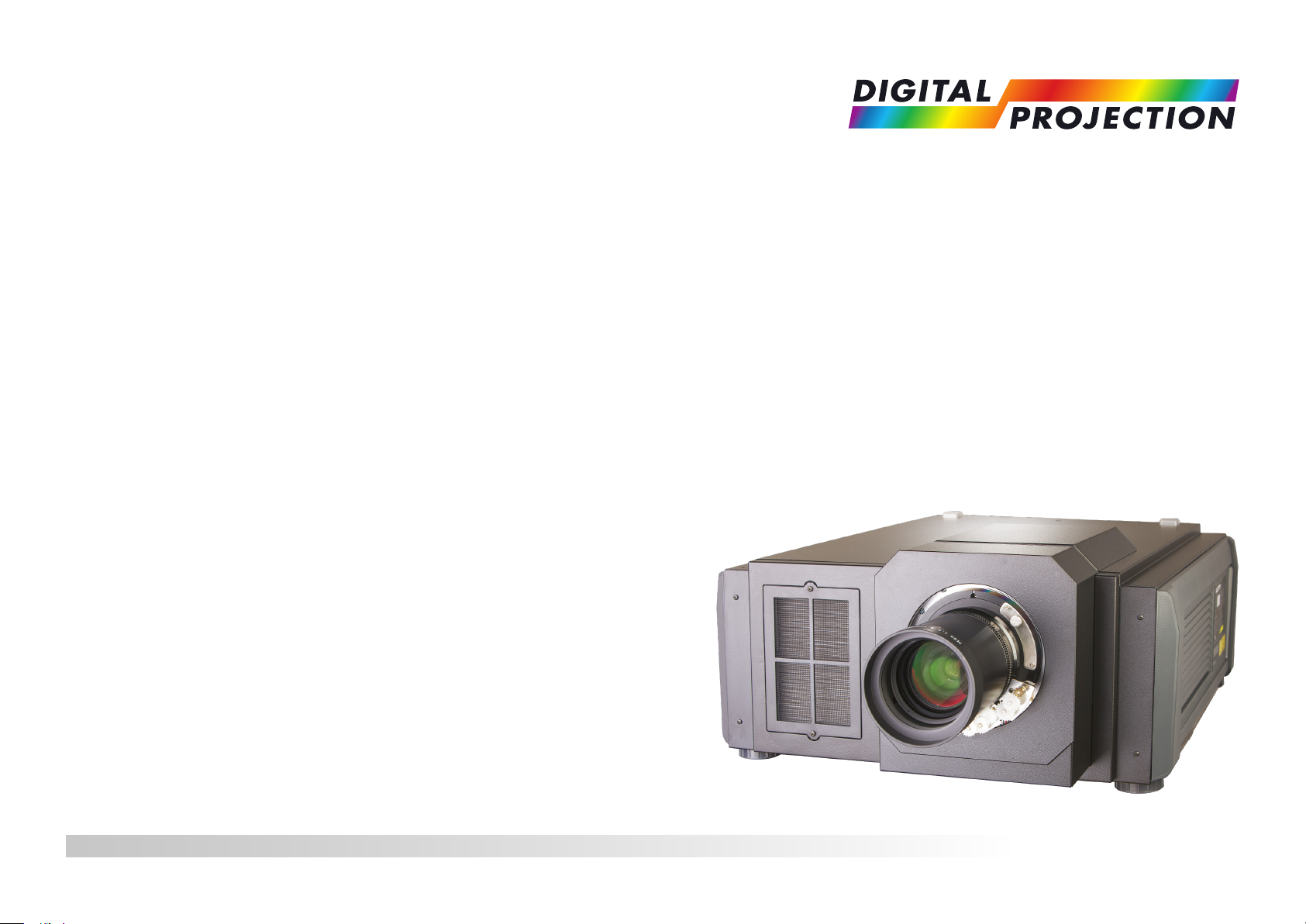
INSIGHT 4K Laser Series
High Brightness Digital Video Projector
4INSTALLATION AND QUICK-START GUIDE
4CONNECTION GUIDE
4OPERATING GUIDE
4REFERENCE GUIDE
Rev C June 2016
116-355C
Page 2

Digital Projection INSIGHT 4K Laser Series
About This Document
Follow the instructions in this manual carefully to ensure safe and long-lasting use of the projector.
Symbols used in this manual
Many pages in this document have a dedicated area for notes. The information in that area is accompanied by the following symbols:
WARNING: this symbol indicates that there is a danger of physical injury to yourself and/or damage to the equipment unless
the instructions are closely followed.
ELECTRICAL WARNING: this symbol indicates that there is a danger of electrical shock unless the instructions are closely
followed.
LASER WARNING: this symbol indicates that there is a potential hazard of eye exposure to laser radiation unless the
instructions are closely followed.
NOTE: this symbol indicates that there is some important information that you should read.
Product revision
Because we at Digital Projection continually strive to improve our products, we may change specications and designs, and add new features
without prior notice.
Notes
Legal notice
Trademarks and trade names mentioned in this document remain the property of their respective owners.
Digital Projection disclaims any proprietary interest in trademarks and trade names other than its own.
Copyright © 2016 Digital Projection Ltd. All rights reserved.
Rev C June 2016
page i
Page 3
Digital Projection INSIGHT 4K Laser Series
Laser Information
LASER LIGHT
AVOID DIRECT EYE EXPOSURE
CLASS 3R LASER PRODUCT
455-470nm <13Watts
CLASSIFIED EN/IEC 60825-1 2007
Caution-useofcontrolsoradjustmentsorperformanceofproceduresotherthanthosespeciedhereinmayresultin
hazardous radiation exposure.
Notes
Rev C June 2016
page ii
Page 4

Digital Projection INSIGHT 4K Laser Series
Introduction
Congratulations on your purchase of this Digital Projection product.
Your projector has the following key features:
• 4K resolution up to 60 fps via single DisplayPort input.
• Dual Pipe input capability (2 x DisplayPort 1.2).
• Full 4K 3D display capability.
• Scaling of HDMI 1.4 formats to 4K resolution.
• 3G-SDI.
• Blanking control for custom input window sizing.
• Control via LAN and RS232.
• Motorised lens mount.
A serial number is located on the product label. Record it here:
Notes
Rev C June 2016
page iii
Page 5

Digital Projection INSIGHT 4K Laser Series
CONTENTS
INSTALLATION AND QUICK-START GUIDE ..............................1
CONNECTING THE POWER SUPPLY ............................................. 3
PROJECTOR OVERVIEW ............................................................... 4
Front and rear views ............................................................................. 4
Control panel ......................................................................................... 5
Control panel button indicators ............................................................. 6
Status indicators.................................................................................... 7
POSITIONING THE SCREEN AND PROJECTOR ............................. 8
Tilting restrictions .................................................................................. 9
FITTING THE LENS ...................................................................... 10
CLEANING AND REPLACING THE FILTERS ................................ 11
Rear lters ........................................................................................... 11
Front lter ............................................................................................ 13
Reset the air lter usage time ............................................................. 15
OPERATING THE PROJECTOR .................................................... 16
Switching the projector on ................................................................... 16
Switching the projector off ................................................................... 17
Selecting a title or test pattern............................................................. 18
Selecting a title.................................................................................... 18
Selecting a test pattern .......................................................................... 19
Adjusting the lens ................................................................................ 20
Adjusting the brightness ...................................................................... 21
CONNECTION GUIDE ............................................................................23
SIGNAL INPUTS .......................................................................... 25
Main connections panel ...................................................................... 25
3D Sync ............................................................................................ 26
Indicators on the main connections panel ................................................... 27
Option board ....................................................................................... 28
EDID on the DVI, HDMI and DisplayPort inputs ................................. 29
Using HDMI/DVI/DisplayPort switchers with the projector ............................... 29
CONTROL CONNECTIONS ........................................................... 30
OPERATING GUIDE ................................................................................31
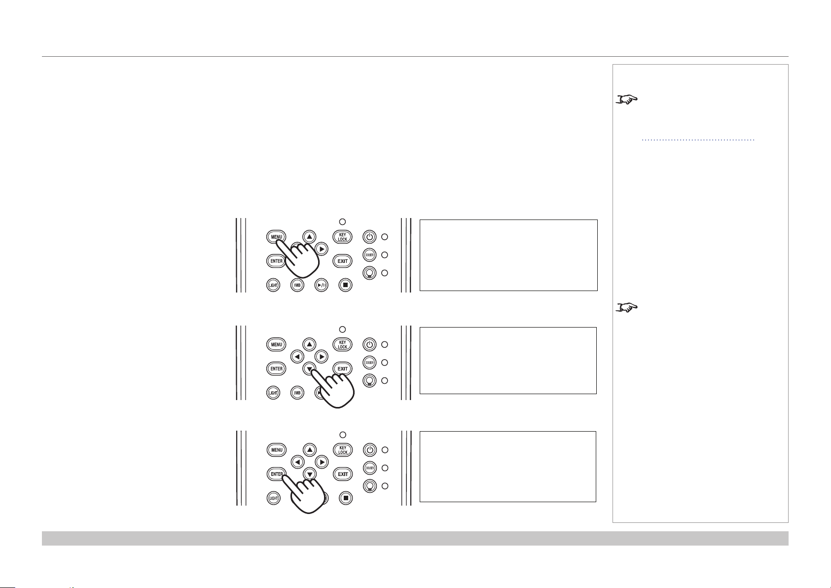
USING THE CONTROL PANEL ..................................................... 33
LCD display overview.......................................................................... 33
In STANDBY mode .............................................................................. 33
In operation ........................................................................................ 33
When showing menus ........................................................................... 34
Locking and unlocking the control panel ............................................. 35
Working with menus ........................................................................... 36
Entering alphanumeric values ................................................................. 36
Rev C June 2016
page iv
Page 6

Digital Projection INSIGHT 4K Laser Series
CONTENTS (continued)
USING THE PROJECTOR ............................................................. 37
Title Select menu ................................................................................ 37
Selecting a test pattern .......................................................................... 37
Conguration menu ............................................................................. 38
Light Setup ........................................................................................ 38
Lens Control ....................................................................................... 38
Reset................................................................................................ 38
Information menu ................................................................................ 39
Light Output ....................................................................................... 39
Preset Button ...................................................................................... 39
Usage ............................................................................................... 39
Error Code ......................................................................................... 39
Version ............................................................................................. 40
IP Address ......................................................................................... 41
Setup Date ......................................................................................... 41
Option Status ...................................................................................... 41
REFERENCE GUIDE ................................................................................43
THE DMD™ .................................................................................. 45
CHOOSING A LENS ..................................................................... 47
SCREEN REQUIREMENTS ........................................................... 48
Fitting the image to the DMD™ ........................................................... 48
Diagonal screen sizes ......................................................................... 49
Fitting the image to the screen ............................................................ 50
Positioning the screen and projector ................................................... 51
POSITIONING THE IMAGE ........................................................... 52
Maximum offset range ......................................................................... 54
ASPECT RATIOS EXPLAINED ...................................................... 55
APPENDIX A: LENS PART NUMBERS .......................................... 56
APPENDIX B: LENS CHARTS ...................................................... 57
How to use the lens charts ..................................................................... 57
Lens chart, up to 100 m throw ................................................................. 58
Lens chart, 10 m throw in detail ............................................................... 59
APPENDIX C: SUPPORTED SIGNAL INPUT MODES .................... 60
ICP60 .................................................................................................. 60
Option board ....................................................................................... 61
Screen allocation of Option board input signals ........................................... 62
APPENDIX D: MENU MAP ............................................................ 63
APPENDIX E: WIRING DETAILS ................................................... 65
Signal inputs - main connections panel............................................... 65
HDMI ................................................................................................ 65
DisplayPort ........................................................................................ 66
Signal inputs - option board ................................................................ 67
DVI .................................................................................................. 67
3G-SDI In .......................................................................................... 68
Control connections ............................................................................ 69
LAN ................................................................................................. 69
RS232 .............................................................................................. 69
3D Sync IN and 3D Sync OUT ................................................................ 69
APPENDIX F: GLOSSARY OF TERMS .......................................... 70
Rev C June 2016
page v
Page 7

Digital Projection INSIGHT 4K Laser Series
CONTENTS (continued)
APPENDIX G: EARLIER VERSIONS ............................................. 79
How to check the version of your projector ......................................... 79
Lens assembly and tting.................................................................... 80
Assembling the lens ............................................................................. 80
Inserting a new lens ............................................................................. 82
Removing the lens ............................................................................... 85
Lens part numbers .............................................................................. 87
TECHNICAL SPECIFICATIONS .................................................... 88
Models................................................................................................. 88
Inputs and outputs............................................................................... 89
Bandwidth ........................................................................................... 89
Remote control and keypad ................................................................ 89
Automation control .............................................................................. 89
Color temperature ............................................................................... 89
Lenses................................................................................................. 90
Lens mount ......................................................................................... 90
Mechanical mounting .......................................................................... 90
Orientation........................................................................................... 90
Electrical and physical specications .................................................. 91
Safety & EMC regulations ................................................................... 91
Rev C June 2016
page vi
Page 8

Digital Projection INSIGHT 4K Laser Series
This page is intentionally left blank.
Page 9

INSIGHT 4K Laser Series
High Brightness Digital Video Projector
4
INSTALLATION AND QUICK-START GUIDE
Rev C June 2016
Page 10

Digital Projection INSIGHT 4K Laser Series
IN THIS GUIDE
IN THIS GUIDE
Connecting The Power Supply ........................................................................ 3
Projector Overview ............................................................................................. 4
Front and rear views ...................................................................................................4
Control panel ...............................................................................................................5
Control panel button indicators .................................................................................6
Status indicators .........................................................................................................7
Positioning The Screen And Projector ......................................................... 8
Tilting restrictions .......................................................................................................9
Fitting The Lens ................................................................................................ 10
Cleaning And Replacing The Filters ........................................................... 11
Rearlters .................................................................................................................11
Frontlter ..................................................................................................................13
Resettheairlterusagetime ..................................................................................15
Operating The Projector ................................................................................. 16
Switching the projector on .......................................................................................16
Switching the projector off .......................................................................................17
Selecting a title or test pattern .................................................................................18
Selecting a title ................................................................................................................18
Selecting a test pattern ...................................................................................................19
Adjusting the lens .....................................................................................................20
Adjusting the brightness ..........................................................................................21
Installation and Quick-Start Guide
Rev C June 2016
Page 11
Digital Projection INSIGHT 4K Laser Series
CONNECTING THE POWER SUPPLY
Connecting The Power Supply
When the projector is viewed from the back, the AC mains
inlet 1 is located on the right hand side, toward the rear.
Make sure the power switch 2 above the inlet is in the
OFF position, then push the mains connector in rmly.
Notes
Use only the power cable
provided.
Ensure that the power outlet
includes a ground connection as
this equipment MUST be earthed.
Handle the power cable carefully
and avoid sharp bends. Do not
use a damaged power cable.
1
2
Installation and Quick-Start Guide
Rev C June 2016
page 3
Page 12
Digital Projection INSIGHT 4K Laser Series
PROJECTOR OVERVIEW
Projector Overview
Front and rear views
Airinletandlter
1
SYSTEM status indicator
2
3
4
5
6
7
8
9
When the projector is operating normally, this
indicator lights green or orange. If an error
occurs, the light becomes red. Depending on the
scenario, the light can be steady or ashing.
LIGHT status indicator
Turns on when the light source is switched on.
Lens
Air outlet
Airinletandlter
Air outlet
Power switch and power connection
Control panel with LED screen
1
4
Front view
7 86
5
9 10 10
32
Notes
Connections
10
Adjustable feet
10
Installation and Quick-Start Guide
11
Rear view
11
Rev C June 2016
page 4
Page 13
Digital Projection INSIGHT 4K Laser Series
PROJECTOR OVERVIEW
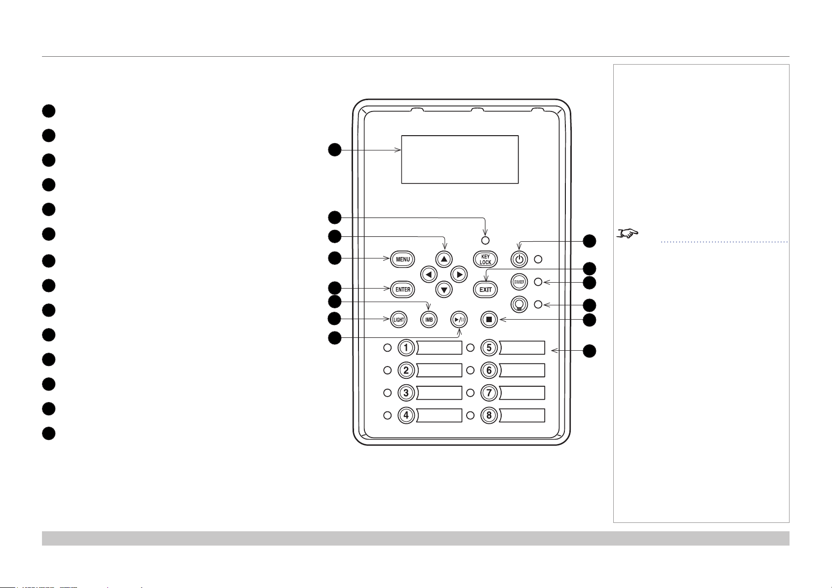
Control panel
LCD display
1
KEY LOCK button (with indicator)
2
Arrow buttons
3
MENU button
4
ENTER button
5
not used in this conguration
6
(except for entering alphanumeric values)
LIGHT button
7
not used in this conguration
8
POWER button (with indicator)
9
EXIT button
10
DOUSER button (with indicator)
11
Notes
1
2
3
4
5
6
7
8
9
10
11
12
13
14
See Entering alphanumeric values
in the Operating Guide.
LIGHT ON / OFF button (with indicator)
12
not used in this conguration
13
Preset buttons 1 to 8 (with indicators)
14
Installation and Quick-Start Guide
Rev C June 2016
page 5
Page 14
Digital Projection INSIGHT 4K Laser Series
PROJECTOR OVERVIEW
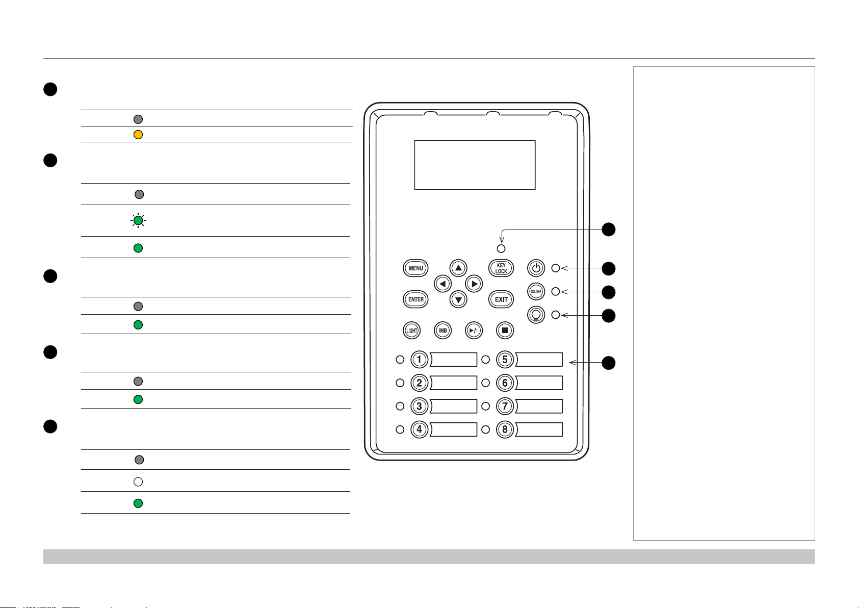
Control panel button indicators
KEY LOCK
1
Behavior Meaning
Off Key lock is inactive.
On Key lock is activated.
2
POWER ON / OFF
Behavior Meaning
Off
Flashing
green
Steady
green
3
DOUSER ON / OFF
Behavior Meaning
Off The douser is opened.
Steady
green
4
LIGHT ON / OFF
Behavior Meaning
Off The light source is switched off.
Steady
green
The projector is switched off from the power supply
or in STANDBY mode.
The projector is warming up (preparing to switch ON)
or cooling down (preparing to switch OFF).
The projector is switched on.
The douser is closed.
The light source is switched on.
Notes
1
2
3
4
5
5
Presets
Behavior Meaning
Off
Steady
white
Steady
green
The title is not assigned to the projector.
The title is assigned to the projector but is not
currently in use.
The title is assigned to the projector and is currently
in use.
Installation and Quick-Start Guide
Rev C June 2016
page 6
Page 15
Digital Projection INSIGHT 4K Laser Series
PROJECTOR OVERVIEW
Status indicators
LIGHT status indicator
1
Behavior Meaning
Off The light source is switched off.
On The light source is switched on.
SYSTEM status indicator
2
Behavior Meaning
21
Notes
Off The projector is switched off.
Flashing green The projector is warming up. The douser is closed and the light source is off.
Steady green The projector is switched on.
Flashing amber The projector is cooling down.
Steady amber The projector is in standby.
Flashing red Error, projection cannot continue. Check LCD screen for error message.
Flashing red, with buzzer
Steady red Nonfatal error, projection may continue. Check LCD screen for error message.
Installation and Quick-Start Guide
Error with safety implications. Projection cannot continue. Check LCD screen for error message.
Rev C June 2016
page 7
Page 16
Digital Projection INSIGHT 4K Laser Series
POSITIONING THE SCREEN AND PROJECTOR
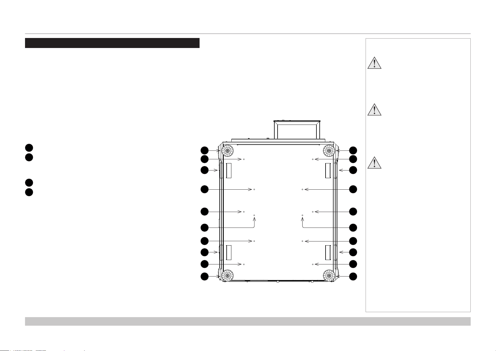
Positioning The Screen And Projector
Installation should be carried out by authorised personnel only.
1. Install the screen, ensuring that it is in the best position for viewing by your audience.
2. Mount the projector, ensuring that it is at a suitable distance from the screen for the image to ll the screen. Set the adjustable feet so that
the projector is level, and perpendicular to the screen.
The drawing below shows the bottom of the projector. The positions of the feet for table mounting, and the xing holes for ceiling mounting
are clearly visible. The illustration also shows the positions of the four handles which facilitate safe carriage.
Four adjustable feet
1
2
Six M6 holes for ceiling mount (set A)
The screws should not penetrate more than 15 mm into the
body of the projector.
Handles for safe carriage
3
4
Six M6 holes for ceiling mount (set B)
The screws should not penetrate more than 15 mm into the
body of the projector.
1
2
3
4
2
1
2
3
4
2
Notes
Always allow the projector
to cool for 5 minutes before
disconnecting the power or
moving the projector.
Ensure that there is at least 30
cm (12 in) of space between the
ventilation outlets and any wall,
and 10 cm (4 in) on all other
sides.
Projectors are not designed to
be stacked on top of each other
unless a rigging frame is used.
Installation and Quick-Start Guide
44
4
3
2
1
4
3
2
1
Rev C June 2016
page 8
Page 17
Digital Projection INSIGHT 4K Laser Series
POSITIONING THE SCREEN AND PROJECTOR
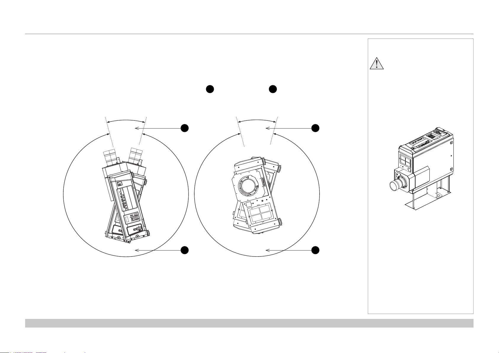
Tilting restrictions
The projector can be operated in numerous positions.
The only non-workable angles are:
• Upright mode with lens pointing upward.
• Portrait mode with inputs facing downward.
The diagram below illustrates both positions showing non-workable angles 1 and workable angles 2:
30°
1
30°
Notes
Portrait mode installation requires
ttingasafetyguardunderneath
the projector (as shown in the
illustration below). Unauthorised
personnel should not attempt to
carry out portrait mode
installation. Please contact Digital
Projection or a dealer if you wish
to use the projector in portrait
mode.
1
Installation and Quick-Start Guide
330°
Pointing Up
2
330°
2
Roll (Portrait)
Rev C June 2016
page 9
Page 18
Digital Projection INSIGHT 4K Laser Series
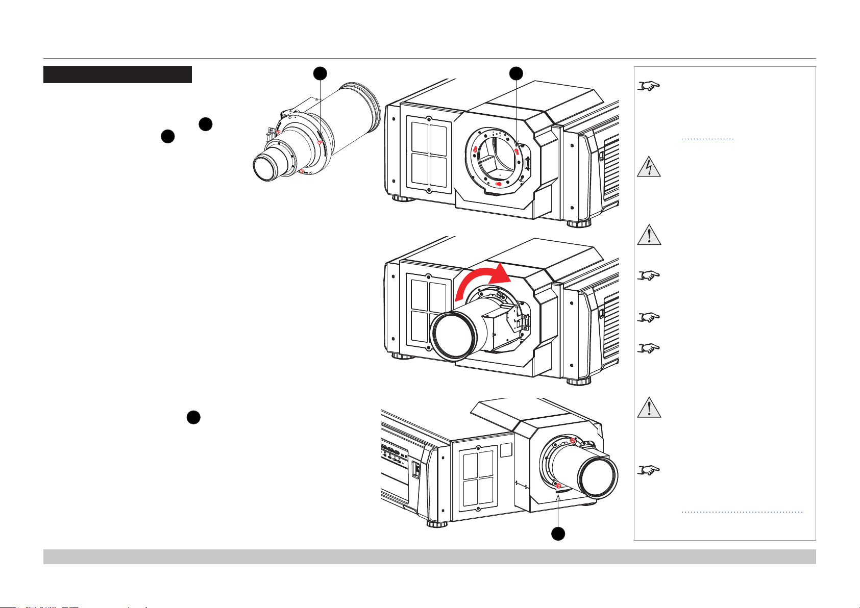
FITTING THE LENS
Fitting The Lens
1. Insert the lens into the mount.
Engage the three locating studs 1 into
the corresponding slots 2 on the mount.
2. Rotate the lens clockwise until the studs
slide all the way into the slots.
1 2
Notes
This procedure applies to version
C of the projector. If your projector
is an earlier version or if you are
unsure which version you have,
see Appendix G in the Reference
Guide.
Before changing the lens,
always make sure the projector
is switched off and fully
disconnected from its power
supply.
When changing the lens, avoid
using excessive force as this may
damage the equipment.
Take care to preserve the original
lens packaging and protective caps
for future use.
The projector will not power on
without the lens tted.
Before turning on the projector,
please ensure the protective caps
are removed from the front and rear
of the lens.
3. Tighten the two xing screws 3 on the
lens collar.
Installation and Quick-Start Guide
Thetwoxingscrewsmustbe
tightened to at least a torque
of 0.5 N-m using a screwdriver.
Loose screws might lead to the
lens falling off.
When a new lens is tted, a
calibration procedure must be
carried out. For more information,
see Calibrating zoom and focus
further in this guide.
3
Rev C June 2016
page 10
Page 19
Digital Projection INSIGHT 4K Laser Series
CLEANING AND REPLACING THE FILTERS
Cleaning And Replacing The Filters
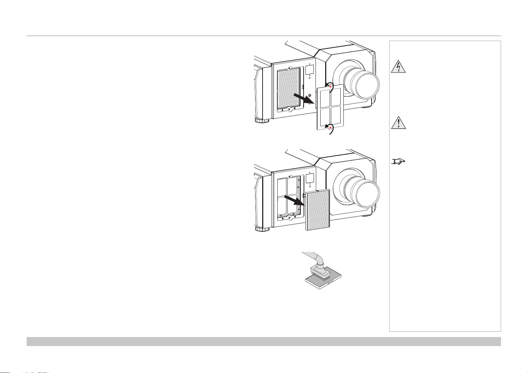
Rear lters
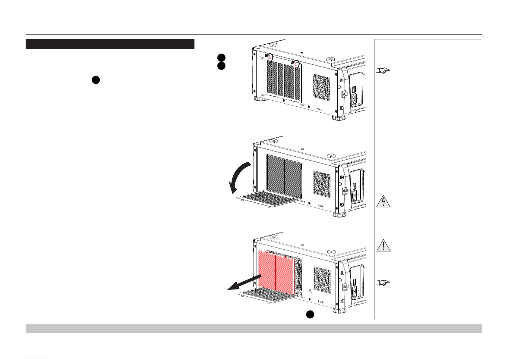
1. Loosen the two knobs 1 holding the lter cover by turning them
counterclockwise.
Use a Phillips screwdriver if necessary.
2. Tilt the lter cover to open it.
Notes
1
1
The knobs are captive on the
removable cover.
Beforechangingthelters,
always make sure the projector
is switched off and fully
disconnected from its power
supply.
3. Remove the lters. Grasp the top and bottom or left and right ends of
each air lter and remove it by pulling toward you.
Installation and Quick-Start Guide
Whenchangingthelters,avoid
using excessive force as this may
damage the equipment.
Filters should be replaced when
new light sources are tted, or as
necessary upon visual inspection
and in accordance with operating
3
environment.
Rev C June 2016
page 11
Page 20
Digital Projection INSIGHT 4K Laser Series
CLEANING AND REPLACING THE FILTERS
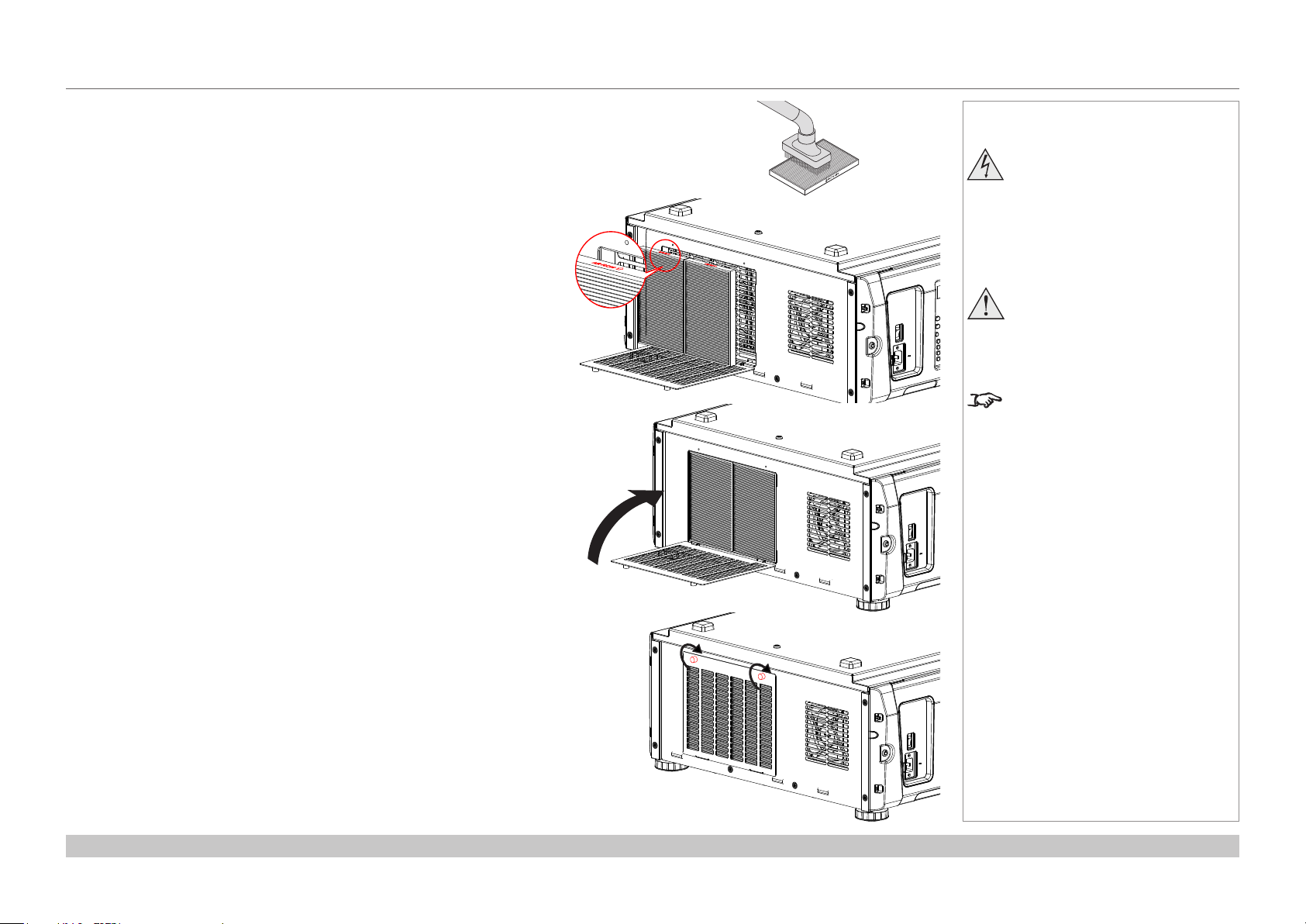
4. If you are replacing the lters, skip this step.
To clean the lters, use a vacuum cleaner brush attachment to vacuum
away dust from the air lters. Avoid making direct contact without an
attachment or using a nozzle attachment.
5. Mount the air lters to the projector. Look for an arrow (AIR FLOW↑)
indicating the installation direction on the side of the air lter. Point the
arrow towards the projector.
6. Close the lter cover.
Notes
Beforechangingthelters,
always make sure the projector
is switched off and fully
disconnected from its power
supply.
Whenchangingthelters,avoid
using excessive force as this may
damage the equipment.
Filters should be replaced when
new light sources are tted, or as
necessary upon visual inspection
and in accordance with operating
environment.
7. Tighten the knobs clockwise to secure the cover.
Installation and Quick-Start Guide
Rev C June 2016
page 12
Page 21
Digital Projection INSIGHT 4K Laser Series
CLEANING AND REPLACING THE FILTERS
Front lter
1. Loosen the two captive screws on the lter cover and remove the cover.
2. Remove the air lter.
Notes
Beforechangingthelters,
always make sure the projector
is switched off and fully
disconnected from its power
supply.
Whenchangingthelters,avoid
using excessive force as this may
damage the equipment.
Filters should be replaced when
new light sources are tted, or as
necessary upon visual inspection
and in accordance with operating
environment.
3. If you are replacing the lter, skip this step.
To clean the lter, use a vacuum cleaner brush attachment to vacuum away dust
from the air lter. Avoid making direct contact without an attachment or using a
nozzle attachment.
Installation and Quick-Start Guide
Rev C June 2016
page 13
Page 22
Digital Projection INSIGHT 4K Laser Series
CLEANING AND REPLACING THE FILTERS
4. Mount the air lter to the projector.
Look for an arrow indicating the installation direction on the side of the air
lter. Point the arrow towards the projector.
5. Mount the lter cover to the projector. Tighten the two captive screws to
secure the cover.
Notes
Beforechangingthelters,
always make sure the projector
is switched off and fully
disconnected from its power
supply.
Whenchangingthelters,avoid
using excessive force as this may
damage the equipment.
Filters should be replaced when
new light sources are tted, or as
necessary upon visual inspection
and in accordance with operating
environment.
Installation and Quick-Start Guide
Rev C June 2016
page 14
Page 23

Digital Projection INSIGHT 4K Laser Series
Reset
CLEANING AND REPLACING THE FILTERS
Reset the air lter usage time
1. Turn on the projector.
2. Open the menu and go to Conguration > Reset.
Filter Usage resets the lter usage time.
Filter Usage
Reset
Notes
Filters should be replaced when
new light sources are tted, or as
necessary upon visual inspection
and in accordance with operating
environment.
Installation and Quick-Start Guide
Rev C June 2016
page 15
Page 24
Digital Projection INSIGHT 4K Laser Series
OPERATING THE PROJECTOR
Operating The Projector
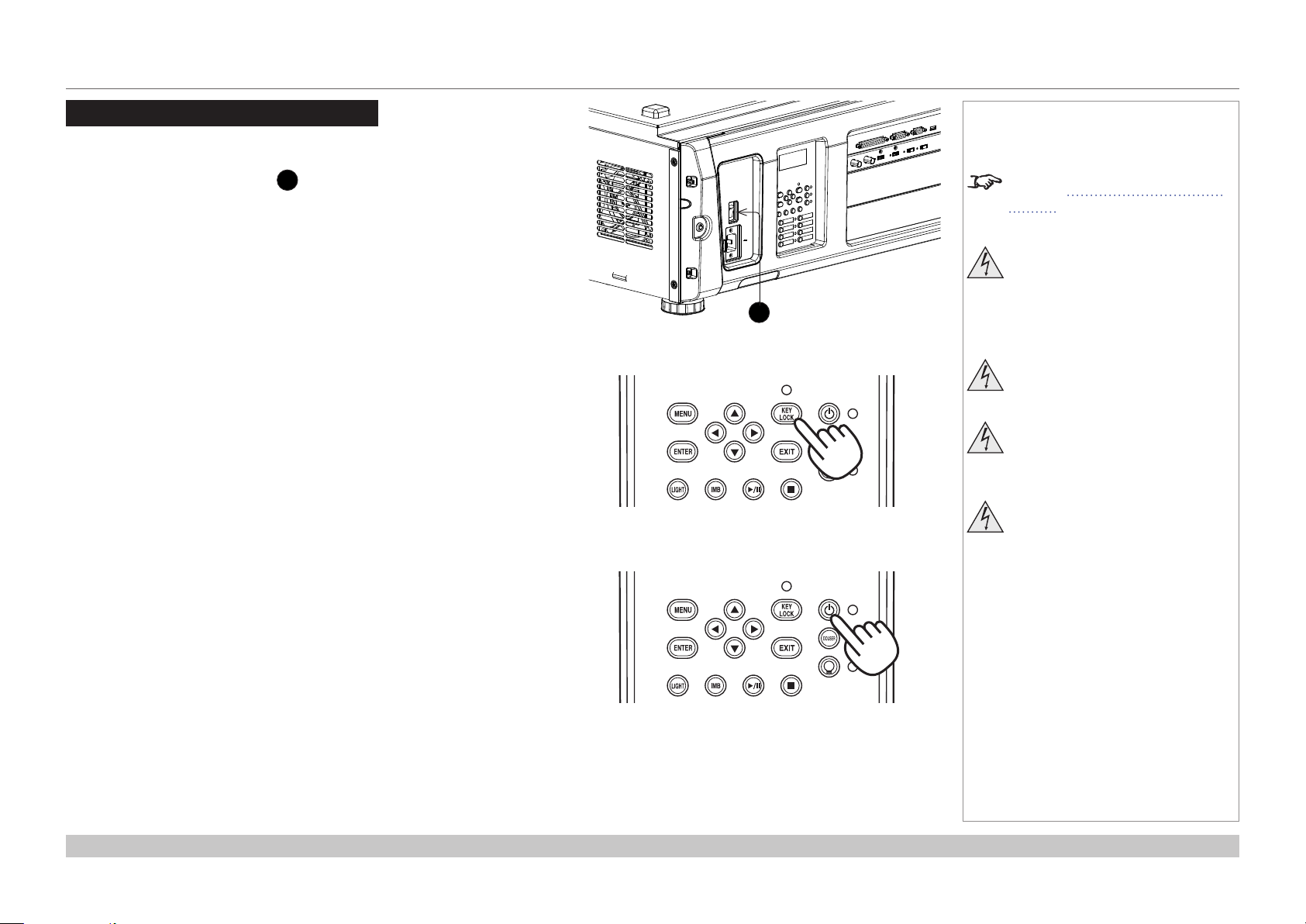
Switching the projector on
1. Make sure the power switch 1 above the AC mains inlet is in the OFF
position. Connect the power cable between the mains supply and the
projector, then turn the power switch on.
The SYSTEM status indicator lights a steady amber to show that the
projector is now in STANDBY mode.
2. (optional step) If no button is pressed within 30 seconds of the projector
entering STANDBY mode, the control panel becomes locked.
To unlock the control panel, press and hold the KEY LOCK button for one
second or longer.
3. To switch from STANDBY to ON mode, press and hold the POWER button
for three seconds or longer.
During the startup process, the SYSTEM status indicator ashes green.
When the projector is fully switched on, the SYSTEM status indicator lights a
steady green.
Notes
See also Connecting The Power
Supply earlier in this guide.
Do not turn off the projector from
the power switch or disconnect
1
the power cord while the
projector is working or cooling
down.
Use only the power cable
provided.
Ensure that the power outlet
includes a ground connection as
this equipment MUST be earthed.
Handle the power cable carefully
and avoid sharp bends. Do not
use a damaged power cable.
Installation and Quick-Start Guide
Rev C June 2016
page 16
Page 25
Digital Projection INSIGHT 4K Laser Series
OPERATING THE PROJECTOR
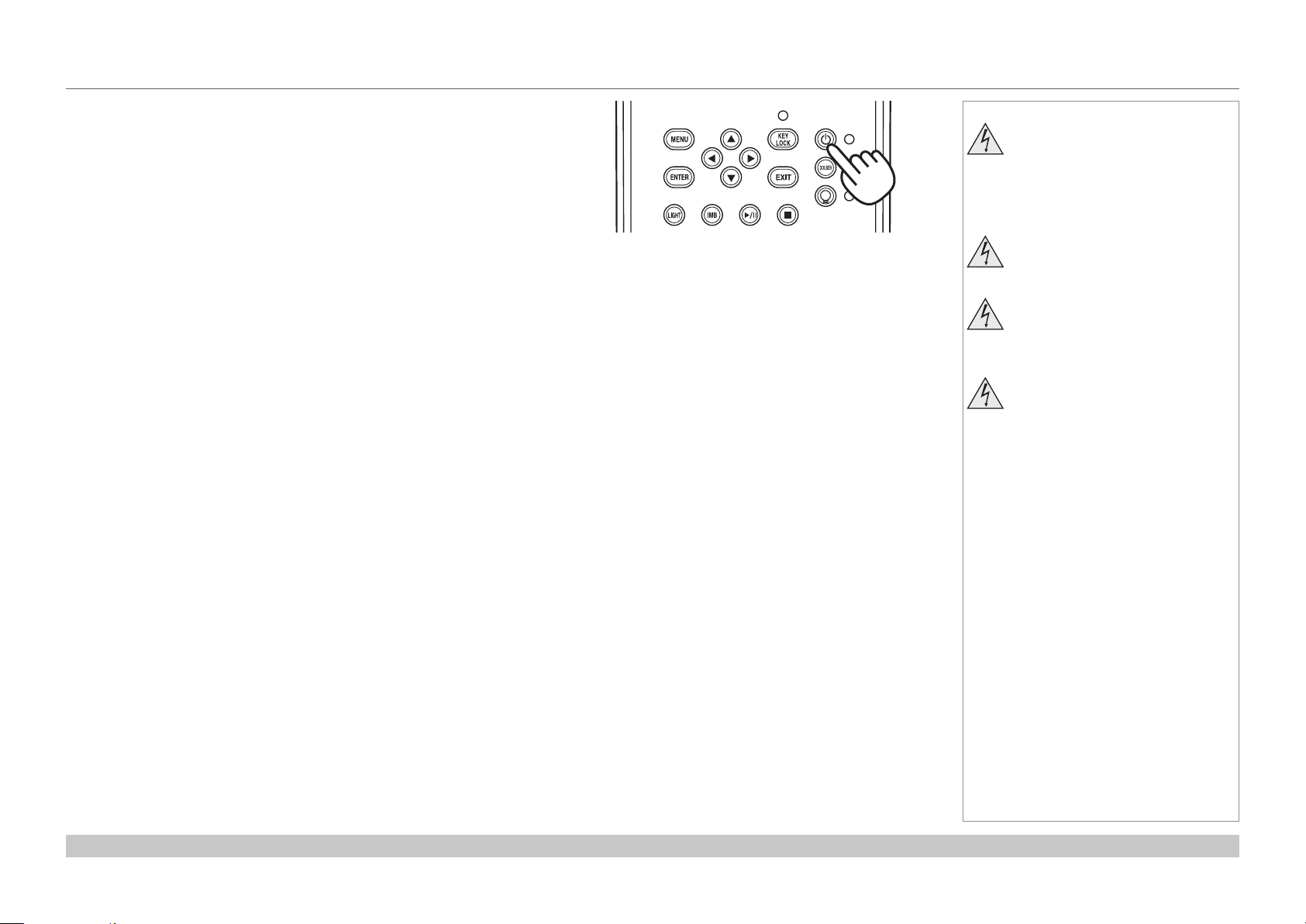
Switching the projector off
1. Press and hold the POWER button for three seconds or longer.
The light source switches off and the projector begins cooling down. During
the cooling down process, the SYSTEM status indicator ashes amber. The
fan continues to work and a message is displayed on the LCD screen to
show that the projector is still not switched off.
When the fan switches off, the SYSTEM status indicator lights a steady
amber to indicate that the projector is now in STANDBY mode.
2. To switch the projector off completely, turn the power switch OFF.
Notes
Do not turn off the projector from
the power switch or disconnect
the power cord while the
projector is working or cooling
down.
Use only the power cable
provided.
Ensure that the power outlet
includes a ground connection as
this equipment MUST be earthed.
Handle the power cable carefully
and avoid sharp bends. Do not
use a damaged power cable.
Installation and Quick-Start Guide
Rev C June 2016
page 17
Page 26
Digital Projection INSIGHT 4K Laser Series
Title Select
Title Select
Title Name
Title Select
Title Name
OPERATING THE PROJECTOR
Selecting a title or test pattern
The projector arrives with titles and test
patterns already congured. If you need
to change the conguration, contact your
dealer.
Selecting a title
Connect the title you wish to display and
switch on the input source, then switch
on the projector. If necessary, unlock the
keypad.
If the title is assigned a shortcut, press the
shortcut button and the projector will begin
displaying the title.
If there is no shortcut assigned to the title:
1. Press the MENU button.
2. Press the LEFT or RIGHT button to
cycle through the list of menus until Title
Select appears on the LCD screen. The
list of menus is as follows:
• Title Select
• Conguration
• (Title Setup)
• Information
• ...
3. When Title Select is displayed, press
DOWN.
4. Press LEFT or RIGHT to go through the
list of available titles until you reach the
title you wish to display.
5. Press ENTER to conrm your choice.
The projector begins displaying the title.
An asterisk mark (*) appears on the LCD
screen to indicate the current selection.
Notes
For detailed information about
switching on the projector and
unlocking the keypad, see
Switching the projector on earlier
in this guide.
Menus and menu items displayed in
parentheses can only be accessed
by service personnel.
(*)
Installation and Quick-Start Guide
Rev C June 2016
page 18
Page 27

Digital Projection INSIGHT 4K Laser Series
Title Select
Title Select
TEST Pattern
Title Select
TEST Pattern
OPERATING THE PROJECTOR
Selecting a test pattern
Switch on the projector and, if necessary,
unlock the keypad.
If the test pattern is assigned a shortcut, press
the shortcut button and the projector will begin
displaying the test pattern.
If there is no shortcut assigned to the test
pattern:
1. Press the MENU button.
2. Press the LEFT or RIGHT button to
cycle through the list of menus until Title
Select appears on the LCD screen. The
list of menus is as follows:
• Title Select
• Conguration
• (Title Setup)
• Information
• ...
3. When Title Select is displayed, press
DOWN.
4. Press LEFT or RIGHT until Title Select
is set to TEST Pattern.
5. Press DOWN again, then press LEFT or
RIGHT to cycle through the list of test
patterns.
6. When you have arrived at the test pattern
you wish to display, press ENTER to
conrm your choice. The projector begins
displaying the test pattern. An asterisk
mark (*) appears on the LCD screen to
indicate the current selection.
To cancel test pattern display, cycle through
the list again and select OFF, then press
ENTER to conrm your choice.
Notes
For detailed information about
switching on the projector and
unlocking the keypad, see
Switching the projector on earlier
in this guide.
(*)
Off
(*)
Alignment
Installation and Quick-Start Guide
Rev C June 2016
page 19
Page 28

Digital Projection INSIGHT 4K Laser Series
Configuration
Focus Zoom
Lens Position
Configuration
OPERATING THE PROJECTOR
Adjusting the lens
1. Press MENU.
2. Press the LEFT or RIGHT button to cycle through the list of menus until Conguration
appears on the LCD screen. The list of menus is as follows:
• Title Select
• Conguration
• (Title Setup)
• Information
• ...
3. Press DOWN to enter the Conguration menu, then press the LEFT or RIGHT button
to cycle through conguration submenus until you reach Lens Control.
Lens controls are accessed in two modes - Lens Position and Focus Zoom. Press
ENTER to switch between the two modes.
• In Lens Position mode, use the arrow buttons to shift the lens in the desired
direction.
• In Focus Zoom mode, use:
• UP and DOWN to change the focus,
• LEFT and RIGHT to change the zoom.
Lens Control
•
Notes
Installation and Quick-Start Guide
+ - +
• •
-
Rev C June 2016
page 20
Page 29

Digital Projection INSIGHT 4K Laser Series
Light Setup
OPERATING THE PROJECTOR
Adjusting the brightness
1. Press MENU.
2. Press the LEFT or RIGHT button to cycle through the list of menus until Conguration appears on the LCD screen. The list of menus is
as follows:
• Title Select
• Conguration
• (Title Setup)
• Information
• ...
3. Press DOWN to enter the Conguration menu, then press the LEFT or RIGHT button to
cycle through conguration submenus until you reach Light Setup.
4. Use the LEFT and RIGHT arrow buttons to adjust the brightness.
Adjust
(*)
100 [%] >
Notes
Installation and Quick-Start Guide
Rev C June 2016
page 21
Page 30

Digital Projection INSIGHT 4K Laser Series
This page is intentionally left blank.
Installation and Quick-Start Guide
Page 31

INSIGHT 4K Laser Series
High Brightness Digital Video Projector
4
CONNECTION GUIDE
Rev C June 2016
Page 32

Digital Projection INSIGHT 4K Laser Series
IN THIS GUIDE
IN THIS GUIDE
Signal Inputs ....................................................................................................... 25
Main connections panel ...........................................................................................25
3D Sync ..........................................................................................................................26
Indicators on the main connections panel .......................................................................27
Option board ..............................................................................................................28
EDID on the DVI, HDMI and DisplayPort inputs .....................................................29
Using HDMI/DVI/DisplayPort switchers with the projector ..............................................29
Control Connections ........................................................................................ 30
Connection Guide
Rev C June 2016
Page 33

Digital Projection INSIGHT 4K Laser Series
SIGNAL INPUTS
Signal Inputs
Main connections panel
The following inputs are available on the main connections
panel:
HDMI 1
1
HDMI 1.4
HDMI 2
2
HDMI 1.4
DisplayPort 1
3
DisplayPort 2
4
Notes
1 2 3 4
Connection Guide
Rev C June 2016
page 25
Page 34

Digital Projection INSIGHT 4K Laser Series
SIGNAL INPUTS
3D Sync
3D Sync In
1
Sync input signal
Connect the 3D sync from your graphics card or server.
3D Sync Out
2
Sync output signal
Connect this to your IR emitter or ZScreen.
Notes
1 2
Main connections panel
Connection Guide
Rev C June 2016
page 26
Page 35

Digital Projection INSIGHT 4K Laser Series
SIGNAL INPUTS
Indicators on the main connections panel
1 2 3222 64 5
3D Sync In / Out
1
These indicators light solid green if 3D sync is present.
HDMI 1 / HDMI 2 / DisplayPort 1 / DisplayPort 2
2
Each of these indicators lights a solid green color if the adjacent input is in use.
If the input is selected but the source is not present, the indicator ashes green.
Option A
3
If an input on Option A board is in use, this indicator lights a solid green color.
If an input on Option A board is selected but the source is not present, the indicator ashes green.
Option B
4
This indicator is not used.
Notes
Main connections panel
Power
5
This indicator lights a solid green color if the projector is switched on.
Health
6
This indicator ashes amber, then green, during boot up.
When the projector is switched on and fully functional, the indicator lights solid green.
Connection Guide
Rev C June 2016
page 27
Page 36

Digital Projection INSIGHT 4K Laser Series
SIGNAL INPUTS
Option board
The option board can be installed in addition to the main
board. It is not part of the default hardware conguration.
The following additional inputs can be made available if the
option board is installed:
3G-SDI A
1
3G-SDI
3G-SDI B
2
3G-SDI
3G-SDI C
3
3G-SDI
3G-SDI D
4
3G-SDI
DVI A
5
DVI-D
DVI B
6
DVI-D
Notes
1 2 3 4 5 6
The SDI inputs can be used for both 3G-SDI and HD-SDI.
The four SDI inputs can be used separately with a 2K or 1080p image, which the projector will scale to 4K, or simultaneously, to project an
image from a full 4K source.
The two DVI inputs can be used simultaneously as well, to display native 4K resolution.
Connection Guide
Rev C June 2016
page 28
Page 37

Digital Projection INSIGHT 4K Laser Series
SIGNAL INPUTS
EDID on the DVI, HDMI and DisplayPort inputs
If you are using a computer DVI card or another source that obeys the EDID protocol, the source will automatically congure itself to suit the
projector.
Otherwise please refer to the documentation supplied with the source to manually set the resolution to the DMD™ resolution of the projector
or the nearest suitable setting. Switch off the source, connect to the projector, then switch the source back on again.
Using HDMI/DVI/DisplayPort switchers with the projector
When using an HDMI/DVI/DisplayPort source switcher with the projector, it is important to set the switcher so that it passes the projector
EDID through to the source devices. If this is not done, the projector may not be able to lock to the source or display the source correctly as
its video output timings may not be compatible with those of the projector. Sometimes this is called transparent, pass-through or clone mode.
See your switcher’s manual for information on how to set this mode.
Additionally, sources which use HDCP encryption may not display properly when connected to the projector via a switcher. Refer to the
switcher’s manual for more information.
1
Sources
2
Switcher
1
2
EDID
EDID
3
EDID
Notes
3
Projector
Connection Guide
EDID
The EDIDs in the switcher should be the same as the one in the projector.
Rev C June 2016
page 29
Page 38

Digital Projection INSIGHT 4K Laser Series
CONTROL CONNECTIONS
Control Connections
PC control terminal (RS-232)
1
Use this terminal when controlling the projector in serial connection from a PC.
LAN port (LAN)
2
Use this port when controlling the projector in LAN connection from a PC.
Notes
1 2
Connection Guide
Rev C June 2016
page 30
Page 39

INSIGHT 4K Laser Series
High Brightness Digital Video Projector
4
OPERATING GUIDE
Rev C June 2016
Page 40

Digital Projection INSIGHT 4K Laser Series
IN THIS GUIDE
IN THIS GUIDE
Using The Control Panel ................................................................................. 33
LCD display overview ...............................................................................................33
In STANDBY mode .........................................................................................................33
In operation .....................................................................................................................33
When showing menus .....................................................................................................34
Locking and unlocking the control panel ...............................................................35
Working with menus ................................................................................................36
Entering alphanumeric values .........................................................................................36
Using The Projector ......................................................................................... 37
Title Select menu .......................................................................................................37
Selecting a test pattern ...................................................................................................37
Congurationmenu ..................................................................................................38
Light Setup ......................................................................................................................38
Lens Control ....................................................................................................................38
Reset ...............................................................................................................................38
Information menu ......................................................................................................39
Light Output ....................................................................................................................39
Preset Button ..................................................................................................................39
Usage ..............................................................................................................................39
Error Code ......................................................................................................................39
Version ............................................................................................................................40
IP Address .......................................................................................................................41
Setup Date ......................................................................................................................41
Option Status ..................................................................................................................41
Operating Guide
Rev C June 2016
Page 41

Digital Projection INSIGHT 4K Laser Series
Standby
Light Off
Light 100H
USING THE CONTROL PANEL
Using The Control Panel
LCD display overview
In STANDBY mode
When the projector is in STANDBY mode, the following is displayed on the LCD screen.
In operation
When the projector is in operation, the following is displayed on the LCD screen.
1
2
3
4
80%
Title
292-A
1
Hours of light source use
2
Light source output (brightness)
3
Selected title
4
Selected video input port
Notes
Operating Guide
Rev C June 2016
page 33
Page 42
Digital Projection INSIGHT 4K Laser Series
Title Select
TEST Pattern
USING THE CONTROL PANEL
When showing menus
Typically the LCD display shows information on four lines:
1
2
(*)
Alignment
1
Menu name
2
Submenu or setting name
3
An asterisk indicates the value shown below is the currently assigned value
4
Value of the setting
3
4
Notes
Operating Guide
Rev C June 2016
page 34
Page 43

Digital Projection INSIGHT 4K Laser Series
USING THE CONTROL PANEL
Locking and unlocking the control panel
Depending on the Auto Key Lock setting, the control panel may automatically lock
itself following a period of inactivity.
When the control panel is locked, the KEY LOCK indicator 1 lights amber.
To lock or unlock the control panel, press and hold the KEY LOCK button for one
second or longer.
Notes
1
Operating Guide
Rev C June 2016
page 35
Page 44

Digital Projection INSIGHT 4K Laser Series
USING THE CONTROL PANEL
Working with menus
• To access the projector menus, press MENU.
• Navigate with the arrow buttons:
• Press the UP button to go above the current menu level.
• Press the DOWN button to go below the current menu level.
• When more items are available at the current level, go through the
list using the LEFT and RIGHT arrow buttons.
• To select an item, navigate to the item and press ENTER.
• To return to the higher level, press EXIT.
Entering alphanumeric values
Alphanumeric values are sometimes required, for example when writing the
log le to an external memory location via USB.
To enter an alphanumeric character, use the eight preset buttons, LIGHT
and IMB 1. Each button produces multiple characters. Pressing the button
repeatedly cycles through the characters as shown in the table below.
Button Character
1
2
3
4
5
6
7
8
LIGHT
IMB
Advance to the next position using RIGHT. Return to the previous position
using LEFT. Delete the current character value with DOWN.
A → B → C → 1 → a → b → c → ! ...
D → E → F → 2 → d → e → f → “ ...
G → H → I → 3 → g → h → i → # ...
J- K → L → 4 → j → k → l → $ ...
M → N → O → 5 → m → n → o → % ...
P → Q → R → 6 → p → q → r → & ...
S → T → U → 7 → s → t → u → ‘ ...
V → W → X → 8 → v → w → x → ( ...
Y → Z → / → 9 → y → z → ? → ) ...
* → , → . → 0 → ; → : → + → - ...
Notes
1
Operating Guide
Rev C June 2016
page 36
Page 45

Digital Projection INSIGHT 4K Laser Series
USING THE PROJECTOR
Using The Projector
Title Select menu
Use this menu to select a title to be projected.
The projector contains a list of up to 100 registered titles. Use this menu to select a title from the list.
To select a title:
1. Open the menu. The Title Select menu appears by default.
2. Press DOWN to access the list of available titles.
3. Navigate through the list using the LEFT and RIGHT arrow buttons.
4. Press ENTER to select a title.
Provided the selected title is connected to a signal, the projection should begin immediately.
Selecting a test pattern
1. Navigate to the TEST Pattern title on the list.
2. Press DOWN to access the list of test patterns.
3. Press ENTER to select a test pattern.
The selected test pattern should appear on the screen immediately.
Notes
If the title you want to display is
assigned a preset button, you can
skip the procedure on this page by
simply pressing the preset button.
Up to 16 presets can be assigned
on the projector. Presets 1 to
8 are recalled by pressing the
corresponding preset button. To
recall preset 9 to 16, press and hold
the UP arrow button, then press the
corresponding number button. If,
for example, the preset you wish to
recall is 9, the corresponding keypad
combination is UP + 1. For preset
10, the combination is UP + 2, etc.
Operating Guide
Rev C June 2016
page 37
Page 46

Digital Projection INSIGHT 4K Laser Series
Configuration
Focus Zoom
Lens Position
Configuration
Light Setup
Reset
Reset
USING THE PROJECTOR
Conguration menu
Press DOWN to access various projector settings.
Light Setup
Use this menu to adjust the light output.
Lens Control
Lens controls are accessed in two modes - Lens Position and Focus Zoom. Press ENTER
to switch between the two modes.
• In Lens Position mode, use the arrow buttons to shift the lens in the desired direction.
• In Focus Zoom mode, use:
• UP and DOWN to change the focus,
• LEFT and RIGHT to change the zoom.
Adjust
(*)
100 [%] >
Lens Control
•
+ - +
Notes
Reset
This is used to reset the air lter usage time.
Press the ENTER button, then select Yes in the displayed conrmation screen, and then
press the ENTER button to reset the air lter usage time.
Operating Guide
• •
-
Filter Usage
Rev C June 2016
page 38
Page 47

Digital Projection INSIGHT 4K Laser Series
Information
Preset Button
Usage
Error Code
USING THE PROJECTOR
Information menu
Displays information relating to the light source, the usage time of the projector, the version
information and error codes.
Light Output
Displays the value of the Light Output setting as percentage of the maximum light source
output.
Preset Button
Shows the titles assigned to the sixteen presets stored in the projector’s memory.
Usage
Displays information related to the projector usage, such as the usage time of the projector,
light source, air lters, and fan, and information about the light source replacement cycle.
Projector
Filter
Filter Cleaning
Fan
Light
Light Strike
Phosphor
Diffuser
LCS
Douser Count
Displays the usage time of the projector.
Displays the usage time of the air lters.
Displays the time elapsed since the previous lter cleaning.
Displays the usage time of the fan.
Display of the usage time of the light source and the value that is
displayed is the amount of usage time remaining (approximate).
Displays the number of times the light source has been turned on.
Display of the usage time of the phosphor and the value that is
displayed is the amount of usage time remaining (approximate).
Display of the usage time of the diffuser and the value that is
displayed is the amount of usage time remaining (approximate).
Display of the usage time of LCS (Liquid Cooling System) and
the value that is displayed is the amount of usage time remaining
(approximate).
Displays the number of times the douser has been used.
Light Output
< 63 [%] >
PresetButton1
Title No.8
( Logo )
Projector
( 0 [H] )
Notes
The remaining amount displayed in
Light/Phosphor/Diffuser/LCS is
calculated from the current usage
time with the unused state as 100%
and time to replace as 0%.
Error Code
Displays the error code when an error occurs.
When multiple errors occur, you can display them by pressing the LEFT/RIGHT buttons.
Operating Guide
No Error
( --- )
Rev C June 2016
page 39
Page 48

Digital Projection INSIGHT 4K Laser Series
Information
System
( Ver1.00-A
Version
< 2.0 >
Version
< NOT USED >
Version
< MM01 >
Version
< 05 >
USING THE PROJECTOR
Version
Displays version information about the projector, optional boards, and IMB
System
Displays the version information of the projector.
BIOS
Firmware
Data
Serial No.
Model
SIB
Displays the model name and version information about the signal input board (SIB). When the
projector is in standby mode, the version information displays “---”.
IMB
This item is not available in the current conguration.
Displays the BIOS version of the projector.
Displays the rmware version of the projector.
Displays the data version of the projector.
Displays the serial number of the projector.
Displays the model name of the projector.
Version
Data
)
SIB
NC-80DS
IMB
Notes
Slave
Displays the slave rmware version of the projector.
Laser
Displays the laser light source rmware version of the projector.
Operating Guide
Slave
Laser
Rev C June 2016
page 40
Page 49

Digital Projection INSIGHT 4K Laser Series
IP Address
( 192.168.10.10)
Information
Information
<
>
USING THE PROJECTOR
IP Address
Displays the IP address set up in the projector.
Setup Date
Displays the date when the projector was set up (the starting date of the warranty period).
Option Status
Displays the link status of the device mounted in slot A (media block, signal input board) on
the projector. The device name is displayed in ( ) when the projector is in standby or when
connection to the device cannot be conrmed.
B Not Available: Slot B is not available in this projector.
A Displays the link status of the device in slot A.
• NC-80DS: Signal input board (NC-80DS01-B)
• No Board: No device mounted
<System *>
Setup Date
< 2015/03/03 >
Option Status
B: Not Avail…
A: NC-80DS
Notes
The projector has a default IP
address. Access the IP Address
page to connect the IP address of
the projector to your network. You
can later change the IP address
using a special software application.
Operating Guide
Rev C June 2016
page 41
Page 50

Digital Projection INSIGHT 4K Laser Series
This page is intentionally left blank.
Operating Guide
Page 51

INSIGHT 4K Laser Series
High Brightness Digital Video Projector
4
REFERENCE GUIDE
Rev C June 2016
Page 52

Digital Projection INSIGHT 4K Laser Series
IN THIS GUIDE
IN THIS GUIDE
The DMD™ ........................................................................................................... 45
Choosing A Lens ................................................................................................ 47
Screen Requirements ...................................................................................... 48
Fitting the image to the DMD™ ................................................................................48
Diagonal screen sizes ...............................................................................................49
Fitting the image to the screen ................................................................................50
Positioning the screen and projector ......................................................................51
Positioning The Image .................................................................................... 52
Maximum offset range ..............................................................................................54
Aspect Ratios Explained ................................................................................ 55
Appendix A: Lens Part Numbers .................................................................. 56
Appendix B: Lens Charts ................................................................................ 57
How to use the lens charts ..............................................................................................57
Lens chart, up to 100 m throw ........................................................................................58
Lens chart, 10 m throw in detail ......................................................................................59
Appendix C: Supported Signal Input Modes ............................................ 60
ICP60 ..........................................................................................................................60
Option board ..............................................................................................................61
Screen allocation of Option board input signals ..............................................................62
Appendix D: Menu Map .................................................................................... 63
TITLE SELECT ...........................................................................................................63
CONFIGURATION ......................................................................................................63
(TITLE SETUP) ...........................................................................................................63
INFORMATION ...........................................................................................................64
Appendix E: Wiring Details ............................................................................ 65
Signal inputs - main connections panel .................................................................65
HDMI ...............................................................................................................................65
DisplayPort ......................................................................................................................66
Signal inputs - option board ....................................................................................67
DVI ..................................................................................................................................67
3G-SDI In ........................................................................................................................68
Control connections .................................................................................................69
LAN .................................................................................................................................69
RS232 .............................................................................................................................69
3D Sync IN and 3D Sync OUT ........................................................................................69
Appendix F: Glossary Of Terms ................................................................... 70
Appendix G: Earlier Versions ........................................................................ 79
How to check the version of your projector ...........................................................79
Lensassemblyandtting ........................................................................................80
Assembling the lens ........................................................................................................80
Inserting a new lens ........................................................................................................82
Removing the lens ..........................................................................................................85
Lens part numbers ....................................................................................................87
Technical Specications ................................................................................ 88
Models ........................................................................................................................88
Inputs and outputs ....................................................................................................89
Bandwidth ..................................................................................................................89
Remote control and keypad .....................................................................................89
Automation control ...................................................................................................89
Color temperature .....................................................................................................89
Lenses ........................................................................................................................90
Lens mount ................................................................................................................90
Mechanical mounting ...............................................................................................90
Orientation .................................................................................................................90
Electricalandphysicalspecications ....................................................................91
Safety & EMC regulations ........................................................................................91
Reference Guide
Rev C June 2016
Page 53

Digital Projection INSIGHT 4K Laser Series
THE DMD™
The DMD™
A DMD™ (Digital Micromirror Device™) is a true digital light modulator which utilises an array of approximately 8.8 million moving aluminium
mirrors, with each one representing a pixel in the nal projected image. The outermost micromirrors in the array remain inactive (pond of
mirrors) and are not used in constructing the image.
1
Casing
2
Light shield
3
Pond of mirrors
4
Array
Each mirror element is suspended over address electrodes by a torsion hinge between two posts.
1
Support posts
2
Mirror element
3
Torsion hinges
1
2
3
4
DMD™
1
2
Notes
4
Offset address electrode
Reference Guide
3
4
Mirror element with tilt mechanism
Rev C June 2016
page 45
Page 54

Digital Projection INSIGHT 4K Laser Series
THE DMD™
Depending on the voltage polarity applied, each mirror will either tilt to the left to produce a bright pixel or to the right for a dark pixel. When
light is applied to the complete DMD™, only the light redirected from a mirror tilting to the left is projected.
Notes
1
Projection lens
2
Incoming light from the illumination module
3
Mirror element tilted to the right
4
Mirror element tilted to the left
5
Reectedlight,lefttilt
6
Light dump
7
Reectedlight,righttilt
1
2
3
4
5
6
7
Light ow
The projector optically lters white light from the illumination module into its constituent red, green and blue. Each color illuminates a separate
DMD™ whose modulated output is then recombined with the other two to form the projected full color image.
1
Illumination module
2
Opticallteringoflightintored,greenandblue
3
Projection lens
1 2 3
white light RGB light
4
DMD™ devices
5
Full color image displayed on screen
Reference Guide
blue
light
green
light
4 5
red
light
Filtering process
Rev C June 2016
page 46
Page 55

Digital Projection INSIGHT 4K Laser Series
CHOOSING A LENS
Choosing A Lens
A number of lenses are available. Which lens you choose depends on the screen size, image aspect ratio, throw distance and light output.
The following table shows all available lenses in order of their throw ratios:
Throw ratios Lens extension (±2%) Throw distance range
0.93 : 1 xed lens 272 mm (10.7 in) 0.5 m - 40 m (1.6 ft - 130 ft)
1.13 - 1.72 : 1 zoom lens 240 mm (9.4 in) 2.5 m - 40+ m (8.2 ft - 130+ ft) at 1.13:1
0.5 m - 40+ m (1.6 ft - 130+ ft) at 1.72:1
1.65 - 2.60 : 1 zoom lens 210 mm (8.3 in) 3.5 m - 40+ m (11.5 ft - 130+ ft) at 1.65:1
1.0 m - 40+ m (3.3 ft - 130+ ft) at 2.60:1
2.53 - 4.98 : 1 zoom lens 210 mm (8.3 in) 1.5 m - 40+ m (4.9 ft - 130+ ft) at 2.53:1
4.5 m - 40+ m (14.8 ft - 130+ ft) at 4.98:1
To choose a lens, either calculate the throw ratio required, or use the lens charts provided at the end of this guide.
Notes
The information on this page applies
to version C of the projector. If your
projector is an earlier version or if
you are unsure which version you
have, see Appendix G at the end of
this document.
INSIGHT 4K zoom lenses are
capable of covering throw distances
greater than forty metres.
The minimum throw of the zoom
lenses changes depending on the
throw ratio used.
For information about individual lens
part numbers, see Appendix A at
the end of this document.
Reference Guide
To choose a lens using lens charts,
go to Appendix B at the end of this
document.
Rev C June 2016
page 47
Page 56

Digital Projection INSIGHT 4K Laser Series
SCREEN REQUIREMENTS
Screen Requirements
Fitting the image to the DMD™
The projector supports 4K and Ultra HD formats and is able to achieve 2K and 1080p via frame doubling.
2K and frame doubled 1080p will not utilize the full width of the DMD™, resulting in pillarboxing, as shown in the illustration.
true 4K (also pixel doubled 2K) = 4096 pixels
UHD (also pixel doubled 1080p) = 3840 pixels
Notes
Reference Guide
true 4K, UHD ( also pixel doubled 2K, 1080p) = 2160 pixels
Rev C June 2016
page 48
Page 57

Digital Projection INSIGHT 4K Laser Series
SCREEN REQUIREMENTS
Diagonal screen sizes
Screen sizes are sometimes specied by their diagonal size (D). When dealing
with large screens and projection distances at different aspect ratios, it is more
convenient to measure screen width (W) and height (H).
The example calculations below show how to convert diagonal sizes into width and
height, at various aspect ratios.
TRUE 4K (approximately 1.9 : 1)
W = D x 0.88 H = D x 0.47
UHD (approximately 1.78 : 1)
W = D x 0.87 H = D x 0.49
H = height
Notes
W = width
D = diagonal
Reference Guide
Rev C June 2016
page 49
Page 58

Digital Projection INSIGHT 4K Laser Series
SCREEN REQUIREMENTS
Fitting the image to the screen
It is important that your screen is of sufcient height and
width to display images at all the aspect ratios you are
planning to use.
Use the conversion chart to check that you are able
to display the full image on your screen. If you have
insufcient height or width, you will have to reduce the
overall image size in order to display the full image on
your screen.
1
4K / 2K (1.9:1)
W = H x 1.9, H = W x 0.53
2
UHD / 1080p (16:9 = 1.78:1)
W = H x 1.78, H = W x 0.56
7
6
5
4
3
Screen height
2
1
1 2 3 4 5 6 7 8 9 10
Screen width
1 2
Notes
Reference Guide
Rev C June 2016
page 50
Page 59
Digital Projection INSIGHT 4K Laser Series
SCREEN REQUIREMENTS
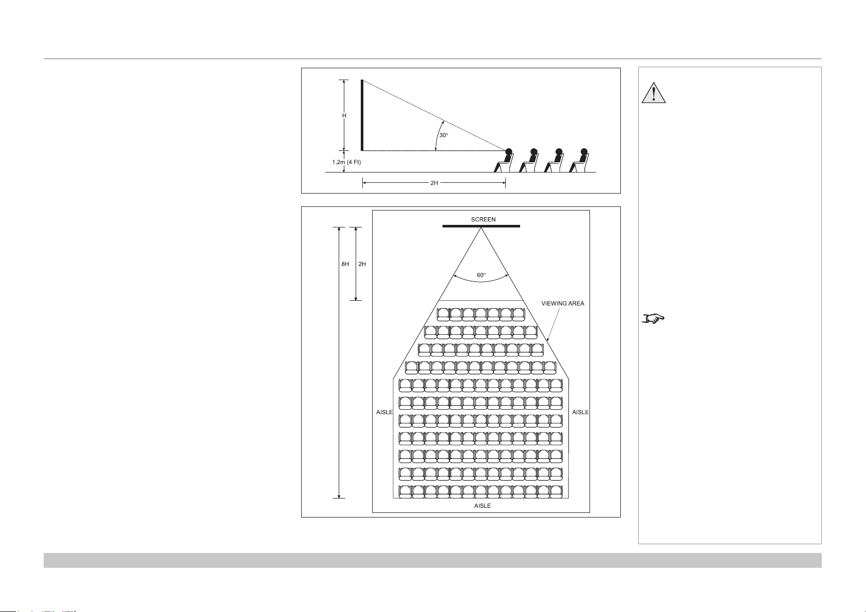
Positioning the screen and projector
For optimum viewing, the screen should be a at surface
perpendicular to the oor. The bottom of the screen should
be 1.2 m (4 feet) above the oor and the front row of the
audience should not have to look up more than 30° to see
the top of the screen.
The distance between the front row of the audience and
the screen should be at least twice the screen height and
the distance between the back row and the screen should
be a maximum of 8 times the screen height. The screen
viewing area should be within a 60° range from the face of
the screen.
Notes
The projector should be installed
as close to the power outlet as
possible.
The power connection should be
easily accessible, so that it can
be disconnected in an emergency.
Ensure that there is at least 30
cm (12 in) of space between the
ventilation outlets and any wall,
and 10 cm (4 in) on all other
sides.
Do not install the projector close
to anything that might be affected
by its operational heat, for
instance, polystyrene ceiling tiles,
curtains etc.
The image can be ipped for rear
projection and displayed without the
need for extra mirrors or equipment.
However, you must ensure that
there is sufcient distance behind
the screen for the projector to be
correctly located.
Rear installation is generally more
complicated and advice should be
sought from your local dealer before
attempting it.
Reference Guide
Rev C June 2016
page 51
Page 60

Digital Projection INSIGHT 4K Laser Series
POSITIONING THE IMAGE
Positioning The Image
The normal position for the projector is at the centre of the screen. However, you can set the projector above or below the centre, or to one side,
and adjust the image using the Lens shift feature (known as rising and falling front) to maintain a geometrically correct image.
Shifting the lens up (rising front)
Notes
For more information on shifting
the lens, see Lens control in the
Operating Guide.
Whenever possible, position the
projector so that the lens is centered
for the highest quality image.
Reference Guide
Centered lens
Shifting the lens down (falling front)
Rev C June 2016
page 52
Page 61

Digital Projection INSIGHT 4K Laser Series
Any single adjustment outside the ranges specied on the following page may result in an unacceptable level of distortion, particularly at the
corners of the image, due to the image passing through the periphery of the lens optics.
If the lens is to be shifted in two directions combined, the maximum range without distortion will be somewhat less, as can be seen in the
illustrations below.
POSITIONING THE IMAGE
Notes
For more information on shifting
the lens, see Lens control in the
Operating Guide.
Reference Guide
Full horizontal or vertical shift Combined shift is reduced
Rev C June 2016
page 53
Page 62

Digital Projection INSIGHT 4K Laser Series
POSITIONING THE IMAGE
Maximum offset range
The maximum offset range available is dependent on which lens is used. Shifting the lens beyond its undistorted limits may be physically
possible, however you may experience excessive vignetting or distortion.
vertical
(frame)
0.93 : 1 xed ±0.210 ±0.080
1.13 - 1.72 : 1 zoom at 1.13:1 0.340 U
0.190 D
at 1.72:1 0.500 U
0.190 D
1.65 - 2.60 : 1 zoom at 1.65:1 0.400 U
0.210 D
at 2.60:1 0.500 U
0.200 D
2.53-4.98 :1 zoom at 2.53:1 0.375 U
0.200 D
at 4.98:1 0.500 U
0.195 D
horizontal
(frame)
0.085 L
0.100 R
0.150 L
0.180 R
0.130 L
0.130 R
0.150 L
0.190 R
0.130 L
0.130 R
0.165 L
0.165 R
Notes
The information on this page applies
to version C of the projector. If your
projector is an earlier version or if
you are unsure which version you
have, see Appendix G at the end of
this document.
For more information on shifting
the lens, see Lens control in the
Operating Guide.
Reference Guide
Rev C June 2016
page 54
Page 63

Digital Projection INSIGHT 4K Laser Series
ASPECT RATIOS EXPLAINED
Aspect Ratios Explained
The appearance of a projected image on the screen depends on:
• the DMD™ resolution, which is 4K with a 4096 x 2160 resolution, corresponding to an aspect ratio of 256:135, or approximately 1.9:1.
• the aspect ratio of the input signal, which is 1.9:1 for 4K and 2K images, or 1.78:1 for UHD or 1080p images.
2K and 1080p are automatically scaled by the projector to ll the height of the DMD™.
The 4K and 2K resolutions have a slightly wider aspect ratio. UHD and scaled 1080p do not ll the width of the DMD™, so they appear
centered, with pillarboxing at the sides, as shown in the illustration.
Notes
Reference Guide
Pillarboxing on UHD and 1080p images
Rev C June 2016
page 55
Page 64

Digital Projection INSIGHT 4K Laser Series
APPENDIX A: LENS PART NUMBERS
Appendix A: Lens Part Numbers
Lens Part No. Focus Range Lens Shift
0.93:1 xed 117-310 0.5 m - 40+ m Vert: 0.210 (U) 0.210 (D) frame, Hor: 0.08 (L) 0.08 (R) 272 mm
1.13 - 1.72:1 zoom 115-627
1.65 - 2.60:1 zoom 115-630
2.53 - 4.98:1 zoom 115-632
At 1.13:1 zoom:
2.5 m - 100+ m
At 1.72:1 zoom:
0.5 m - 100+ m
At 1.65:1 zoom:
3.5 m - 100+ m
At 2.60:1 zoom:
1.0 m - 100+ m
At 2.53:1 zoom:
1.5 m - 100+ m
At 4.98:1 zoom:
4.5 m - 100+ m
At 1.13:1 zoom:
Vert: 0.340 (U) 0.190 (D) frame, Hor: 0.09 (L) 0.09 (R) frame
At 1.72:1 zoom:
Vert: 0.500 (U) 0.190 (D) frame, Hor: 0.16 (L) 0.16 (R) frame
At 1.65:1 zoom:
Vert: 0.400 (U) 0.200 (D) frame, Hor: 0.13 (L) 0.13 (R) frame
At 2.60:1 zoom:
Vert: 0.500 (U) 0.200 (D) frame, Hor: 0.17 (L) 0.17 (R) frame
At 2.53:1 zoom:
Vert: 0.375 (U) 0.200 (D) frame, Hor: 0.13 (L) 0.13 (R) frame
At 4.98:1 zoom:
Vert: 0.500 (U) 0.195 (D) frame, Hor: 0.16 (L) 0.16 (R) frame
Lens
extension
240 mm
210 mm
210 mm
Notes
The information on this page applies
to version C of the projector. If your
projector is an earlier version or if
you are unsure which version you
have, see Appendix G at the end of
this document.
Reference Guide
Rev C June 2016
page 56
Page 65

Digital Projection INSIGHT 4K Laser Series
APPENDIX B: LENS CHARTS
Appendix B: Lens Charts
How to use the lens charts
The lens charts on the following pages provide
a quick guide to the type of lens needed for a
particular projector.
To use the lens charts, you need the following
information:
• The distance between the projector and the
screen (throw distance)
• The maximum width of your screen
In the chart, nd the point where the throw distance
corresponds to the screen width, as shown in the
example below.
Example
For a projector with
• throw distance 30 m, and
• screen width 9 m,
1
Throw distance
2
Screen width
100 m (328.1 ft)
80 m (262.5 ft)
60 m (196.9 ft)
1 2
1
2
Notes
The information in this section
applies to version C of the projector.
If your projector is an earlier version
or if you are unsure which version
you have, see Appendix G at the
end of this document.
4
3
the correct lens would be number 4 in the chart.
Reference Guide
Screen width
40 m (131.2 ft)
20 m (65.6 ft)
20 m
(65.6 ft)
(131.2 ft)
Throw distance
40 m
60 m
(196.9 ft)
80 m
(262.5 ft)
100 m
(328.1 ft)
Rev C June 2016
page 57
Page 66

Digital Projection INSIGHT 4K Laser Series
APPENDIX B: LENS CHARTS
Lens chart, up to 100 m throw
1
0.93:1xedlens
2
1.13-1.72 : 1 zoom lens
3
1.65-2.60 : 1 zoom lens
4
2.53-4.98 : 1 zoom lens
100 m (328.1 ft)
80 m (262.5 ft)
60 m (196.9 ft)
Screen width
40 m (131.2 ft)
21 3 4
Notes
The information in this section
applies to version C of the projector.
If your projector is an earlier version
or if you are unsure which version
you have, see Appendix G at the
end of this document.
Reference Guide
20 m (65.6 ft)
20 m
(65.6 ft)
40 m
(131.2 ft)
Throw distance
60 m
(196.9 ft)
80 m
(262.5 ft)
100 m
(328.1 ft)
The semi-transparent red segment
at the bottom left corner of the chart
is shown on the next page in more
detail.
Rev C June 2016
page 58
Page 67
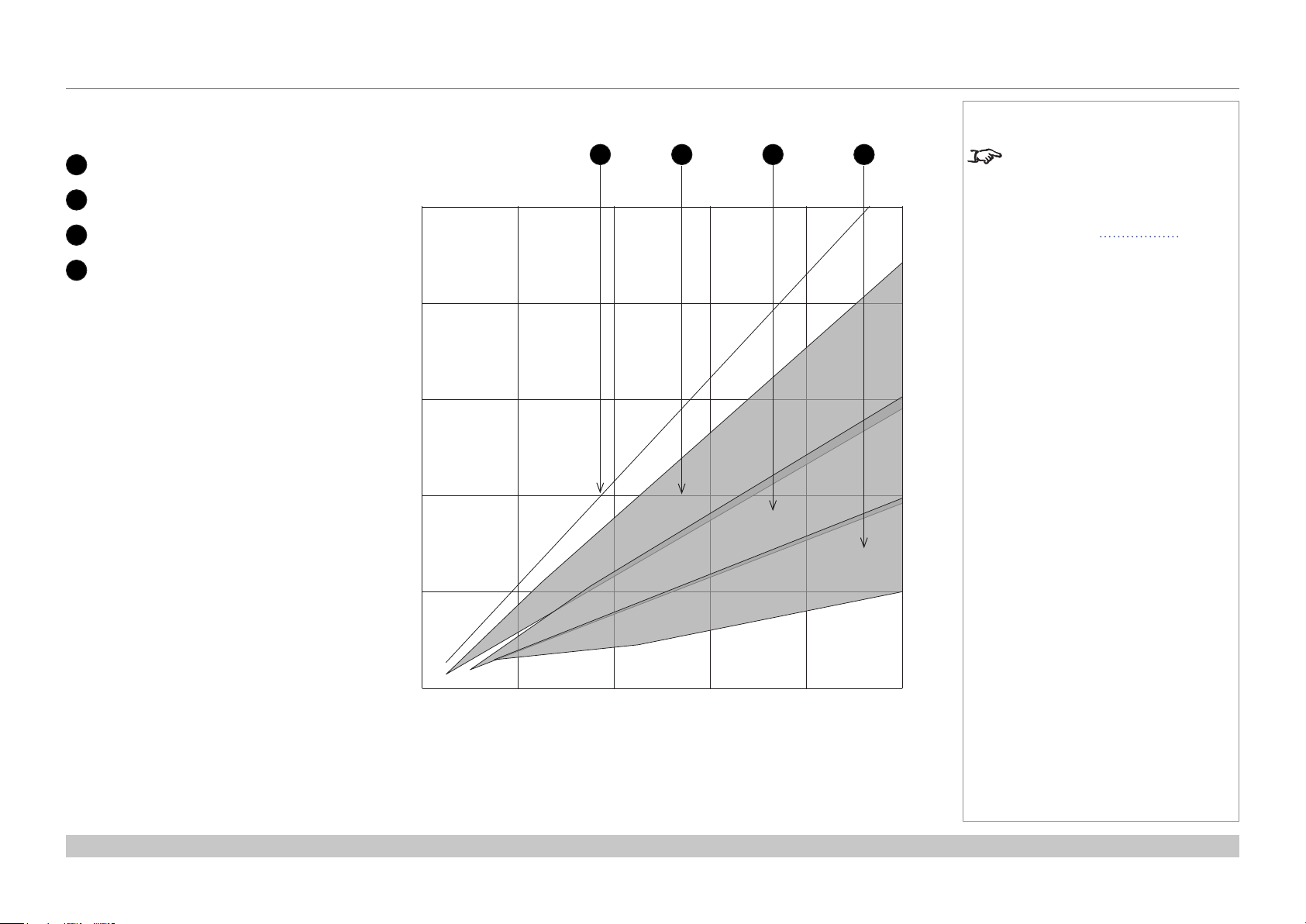
Digital Projection INSIGHT 4K Laser Series
APPENDIX B: LENS CHARTS
Lens chart, 10 m throw in detail
1
0.93:1xedlens
2
1.13-1.72 : 1 zoom lens
3
1.65-2.60 : 1 zoom lens
4
2.53-4.98 : 1 zoom lens
10 m (32.8 ft)
8 m (26.3 ft)
6 m (19.7 ft)
Screen width
4 m (13.1 ft)
21 3 4
Notes
The information in this section
applies to version C of the projector.
If your projector is an earlier version
or if you are unsure which version
you have, see Appendix G at the
end of this document.
Reference Guide
2 m (6.6 ft)
2 m
(6.6 ft)
4 m
(13.1 ft)
Throw distance
6 m
(19.7 ft)
8 m
(26.3 ft)
10 m
(32.8 ft)
Rev C June 2016
page 59
Page 68

Digital Projection INSIGHT 4K Laser Series
APPENDIX C: SUPPORTED SIGNAL INPUT MODES
Appendix C: Supported Signal Input Modes
ICP60
Resolution
Multiplier
Frame Rate
(RGB 4:4:4)
Color Model
(YCrCb 4:2:2)
Max allowable
x 3 — —
x 3 — —
x 3 — —
x 3 — —
x 3 — —
x 3 — —
x 3 — —
x 2 — —
x 2 — —
x 1 — —
x 3 — —
x 3 — —
x 3 — —
x 3 — —
x 3 — —
x 3 — —
x 3 — —
x 3 — —
x 2 — —
x 2 — —
x 2 — —
x 2 — —
HDMI 1.4
DisplayPort
1.2
720p @ 24 Hz
1080p @ 24 Hz
3840 x 2160 @ 24 Hz
4096 x 2160 @ 24 Hz
720p @ 30 Hz
1080p @ 30 Hz
3840 x 2160 @ 30 Hz
720p @ 60 Hz
1080p @ 50/60 Hz
1080p @ 120 Hz
720p @ 24 Hz
1080p @ 24 Hz
3840 x 2160 @ 24 Hz
4096 x 2160 @ 24 Hz
720p @ 30 Hz
1080p @ 30 Hz
3840 x 2160 @ 30 Hz
4096 x 2160 @ 30 Hz
720p @ 60 Hz
1080p @ 50/60 Hz
3840 x 2160 @ 50/60 Hz
4096 x 2160 @ 50/60 Hz
Color Model
Color Model
(YCrCb 4:2:0)
—
—
—
— —
—
—
—
—
—
—
—
—
—
—
—
—
Notes
INSIGHT 4K Laser is capable of
exceeding the Rec. 709 gamut.
HDMI formats up to 2K are
automatically detected and
3D Capability
Dual-pipe
Dual-pipe
Left-Right
East-West
FrameSequential only
converted to RGB, therefore the
projector should be set to RGB.
Formats over 2K are passed
through to the video processing
FPGA in their original color space:
please select RGB or YCrCb as
appropriate.
DisplayPort and HDMI receivers
accept deep color and higher depth
sources inline with DisplayPort 1.2
and HDMI standards. INSIGHT
processing works at up to 12 bits
per color (RGB in gamma space)
and maps to a displayed palette of
16 bits per color (linear space).
Rev B ICP60 is qualied with n-Vidia
graphics cards and not guaranteed
to work with spread spectrum
enabled cards, such as AMD.
Rev C ICP60 onwards has been
qualied with both n-Vidia and AMD
graphics cards.
DisplayPort formats up to
2048x1080 at up to 120 Hz can be
accepted. These can be scaled 2:1
to best t the DMD.
Formats over 2048x1080 can have
a maximum input rate of 60 fps and
are multiplied in the formatter for 3D.
24, 30 and 60 Hz are nominal: the
projector also accepts at least 23.98,
25, 48 and 59.84 Hz.
Reference Guide
Rev C June 2016
page 60
Page 69

Digital Projection INSIGHT 4K Laser Series
APPENDIX C: SUPPORTED SIGNAL INPUT MODES
Option board
Resolution
Color Model
(YCrCb 4:2:0)
DVI (A or B) 720p @ 24 Hz — —
1080p @ 24 Hz — —
720p @ 30 Hz — —
1080p @ 30 Hz — —
720p @ 60 Hz — —
1080p @ 60 Hz — —
Dual DVI (A & B) 3840 x 2160 @ 24 Hz — —
4096 x 2160 @ 24 Hz — —
3840 x 2160 @ 30 Hz — —
4096 x 2160 @ 30 Hz — —
Single 3GSDI
(A, B, C, or D)
Dual 3GSDI
(A & B or C & D)
Quad HDSDI
(A, B, C, & D)
720p @ 24 Hz
1080i @ 24 Hz
1080p @ 24 Hz
720p @ 30 Hz
1080i @ 30 Hz
1080p @ 30 Hz
720p @ 60 Hz
1080i @ 60 Hz
1080p @ 60 Hz
3840 x 2160 @ 24 Hz
4096 x 2160 @ 24 Hz
3840 x 2160 @ 30 Hz
4096 x 2160 @ 30 Hz
3840 x 2160 @ 60 Hz
4096 x 2160 @ 60 Hz
Color Model
(RGB 4:4:4)
Color Model
(YCrCb 4:2:2)
x 3
x 3
x 3
x 3
x 2
x 2
x 3
x 3
x 3
x 3
— x 3
— x 3
— x 3
— x 3
— x 3
— x 3
— x 2
— x 2
— x 2
— x 3
— x 3
— x 3
— x 3
— x 2
— x 2
3D Capability Comments
Multiplier
Frame Rate
FrameSequential only
FrameSequential only
FrameSequential only
FrameSequential only
FrameSequential only
3D is of limited use, as there is no 3D sync
capability.
3D is of limited use as Dual-pipe is not
possible.
3D is of limited use as Dual-pipe is not
possible in SDI and there is no 3D sync
capability.
Notes
3G-SDI is Level B only.
4K interlaced signal is not supported
by ICP.
INSIGHT 4K Laser will accept a
single option card.
Reference Guide
Rev C June 2016
page 61
Page 70

Digital Projection INSIGHT 4K Laser Series
APPENDIX C: SUPPORTED SIGNAL INPUT MODES
Screen allocation of Option board input signals
3G-SDI A
1
3G-SDI B
2
3G-SDI C
3
3G-SDI D
4
DVI A
5
DVI B
6
SDI Quad
DVI Twin
2160
2160
3840 4096
SDI A: 1920 x 1080 SDI B: 1920 x 1080
SDI C: 1920 x 1080 SDI D: 1920 x 1080 SDI C: 2048 x 1080 SDI D: 2048 x 1080
3840 4096
DVI A: 1920 x 2160 DVI B: 1920 x 2160
1 2 3 4 5 6
2160
2160
Notes
SDI A: 2048 x 1080 SDI B: 2048 x 1080
DVI A: 2048 x 2160 DVI B: 2048 x 2160
Reference Guide
Rev C June 2016
page 62
Page 71

Digital Projection INSIGHT 4K Laser Series
APPENDIX D: MENU MAP
Appendix D: Menu Map
Menu Sub Menus Description
TITLE SELECT
Title Memory Name Selects the title of the signal to be projected.
Test Pattern Selects a test pattern to be projected.
CONFIGURATION
Light Setup
Adjust Adjusts the light source brightness (output).
Lens Control
Lens Position Adjusts the position of the projected image.
Focus Zoom Adjusts the size and focus of the projected image.
Reset
(Factory Default) Returns the settings to their default values.
Selects between preset buttons and titles only, LAN settings and all settings.
Filter Usage Initializes the usage time of the air lter.
Filter Cleaning Initializes the lter cleaning time.
(Fan Usage) Initializes the usage time of the fan.
(Light Usage) Initializes the usage time of the light source.
(Phosphor) Initializes the usage time of the phosphor.
(Diffuser) Initializes the usage time of the diffuser.
(LCS) Initializes the usage time of the liquid cooling system.
(Douser Count) Resets the number of times the douser has been used.
(Setup) This menu is inaccessible from the control panel.
(Installation)
(Memory)
Notes
Some of the information in this menu
map is summarised. See the actual
menu on the projector for full details.
Menus and menu items displayed
in parentheses cannot be accessed
from the control panel.
To access such items, you need to
connect the projector to a computer
running a specially designed
application. The software will require
special login credentials.
(TITLE SETUP)
Reference Guide
Rev C June 2016
page 63
Page 72

Digital Projection INSIGHT 4K Laser Series
Menu Sub Menus Description
INFORMATION
Light Output Displays the light source output setting.
Lens Type Displays the lens type setting.
Preset Button
Preset Button 1 - 16 Displays the titles assigned to the preset buttons (<1> to <8>).
Usage Displays information related to projector usage.
Error Code Displays any currently occurring error.
Version
System Displays model name and version information about the projector.
SIB Displays model and version of the signal input board (SIB).
Slave Displays the slave rmware version of the projector.
Laser Displays the laser light source rmware version of the projector.
IP Address
System Displays the IP address of the projector.
Setup Date Displays the date when the projector was set up (starting date of the warranty
period).
Option Status Displays the link status of the device mounted in slot A and projector
APPENDIX D: MENU MAP
Notes
Some of the information in this menu
map is summarised. See the actual
menu on the projector for full details.
Menus and menu items displayed in
parentheses can only be accessed
by service personnel.
Reference Guide
Rev C June 2016
page 64
Page 73

Digital Projection INSIGHT 4K Laser Series
APPENDIX E: WIRING DETAILS
Appendix E: Wiring Details
Signal inputs - main connections panel
HDMI
19 way type A connector
1 TMDS Data 2+
2 TMDS Data 2 Shield
3 TMDS Data 2-
4 TMDS Data 1+
5 TMDS Data 1 Shield
6 TMDS Data 1-
7 TMDS Data 0+
8 TMDS Data 0 Shield
9 TMDS Data 010 TMDS Clock+
11 TMDS Clock Shield
12 TMDS Clock-
13 CEC
14 not connected
15 SCL (DDC Clock)
16 SCA (DDC Data)
17 DDC/CEC Ground
18 +5 V Power
19 Hot Plug Detect
Notes
HDMI: pin view of panel connector
Reference Guide
Rev C June 2016
page 65
Page 74
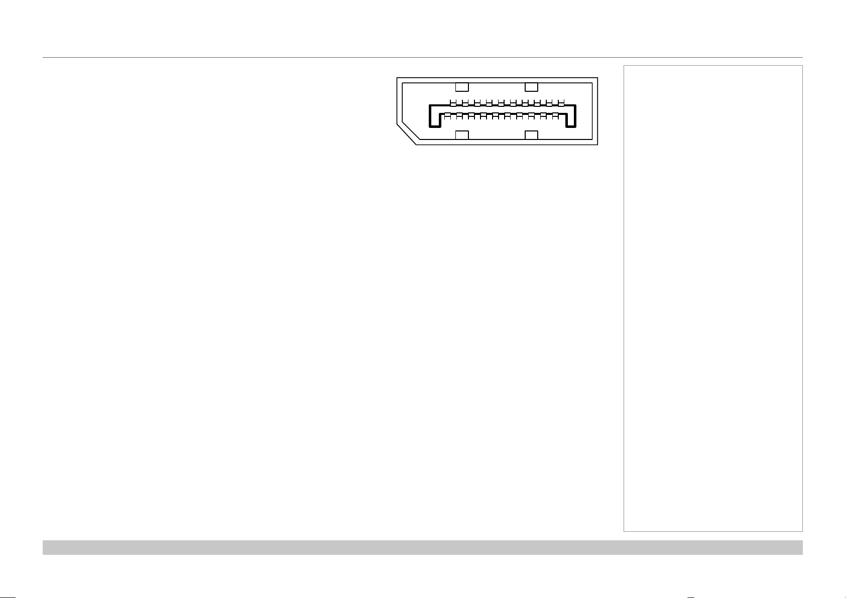
Digital Projection INSIGHT 4K Laser Series
APPENDIX E: WIRING DETAILS
DisplayPort
DisplayPort 1.2
Pin 1 ML_Lane 0 (p) Lane 0 (positive)
Pin 2 GND Ground
Pin 3 ML_Lane 0 (n) Lane 0 (negative)
Pin 4 ML_Lane 1 (p) Lane 1 (positive)
Pin 5 GND Ground
Pin 6 ML_Lane 1 (n) Lane 1 (negative)
Pin 7 ML_Lane 2 (p) Lane 2 (positive)
Pin 8 GND Ground
Pin 9 ML_Lane 2 (n) Lane 2 (negative)
Pin 10 ML_Lane 3 (p) Lane 3 (positive)
Pin 11 GND Ground
Pin 12 ML_Lane 3 (n) Lane 3 (negative)
Pin 13 CONFIG1 connected to Ground1)
Pin 14 CONFIG2 connected to Ground1)
Pin 15 AUX CH (p) Auxiliary Channel (positive)
Pin 16 GND Ground
Pin 17 AUX CH (n) Auxiliary Channel (negative)
Pin 18 Hot Plug Hot Plug Detect
Pin 19 Return Return for Power
Pin 20 DP_PWR Power for connector (3.3 V 500 mA)
Notes
191115171913 7 5 3
21012161820 14 8 6 4
DisplayPort: pin view of panel connector
Reference Guide
Rev C June 2016
page 66
Page 75

Digital Projection INSIGHT 4K Laser Series
APPENDIX E: WIRING DETAILS
Signal inputs - option board
DVI
24 way D-type connector
Pin 1 TMDS data 2− Digital red− (link 1)
Pin 2 TMDS data 2+ Digital red+ (link 1)
Pin 3 TMDS data 2/4 shield
Pin 4 TMDS data 4− Digital green− (link 2)
Pin 5 TMDS data 4+ Digital green+ (link 2)
Pin 6 DDC clock
Pin 7 DDC data
Pin 8 Analog vertical sync
Pin 9 TMDS data 1− Digital green− (link 1)
Pin 10 TMDS data 1+ Digital green+ (link 1)
Pin 11 TMDS data 1/3 shield
Pin 12 TMDS data 3- Digital blue− (link 2)
Pin 13 TMDS data 3+ Digital blue+ (link 2)
Pin 14 +5 V Power for monitor when in standby
Pin 15 Ground Return for pin 14 and analog sync
Pin 16 Hot plug detect
Pin 17 TMDS data 0− Digital blue− (link 1) and digital sync
Pin 18 TMDS data 0+ Digital blue+ (link 1) and digital sync
Pin 19 TMDS data 0/5 shield
Pin 20 TMDS data 5− Digital red− (link 2)
Pin 21 TMDS data 5+ Digital red+ (link 2)
Pin 22 TMDS clock shield
Pin 23 TMDS clock+ Digital clock+ (links 1 and 2)
Pin 24 TMDS clock− Digital clock− (links 1 and 2)
C1 Analog red
C2 Analog green
C3 Analog blue
C4 Analog horizontal sync
C5 Analog ground Return for R, G, and B signals
DVI: pin view of female connector
Notes
The default hardware conguration
does not include an option board,
which can be ordered separately.
High-bandwidth Digital Content
Protection (HDCP) is supported on
this input.
Reference Guide
Rev C June 2016
page 67
Page 76

Digital Projection INSIGHT 4K Laser Series
APPENDIX E: WIRING DETAILS
3G-SDI In
75 ohm BNC
Notes
3G-SDI connector
Reference Guide
Rev C June 2016
page 68
Page 77

Digital Projection INSIGHT 4K Laser Series
APPENDIX E: WIRING DETAILS
Control connections
LAN
RJ45 socket
RS232
9 way D-type connector
Pin
RS-232C
No.
Signal Name
1 CD Carrier detection Not used (N.C.)
2 RXD Reception data Data transmission to an external device
3 TXD Transmission data Data reception from an external device
4 DTR Data Terminal ready
5 GND Signal GND Signal GND
6 DSR Data set ready (Note) Connection to 4 pins
7 RTS Transmission request SYSTEM: Hi-Z (Not used)
8 CTS Transmission available SYSTEM: Fixed at -6.5 V (Not used)
9 RI Ring indicator Not used (N.C.)
Functions as RS-232C Projector Connector Operation
Connection to 6 pins
(Note)
CINEMA: Hi-Z (Used)
CINEMA: ±10.5 V (Used: Depends on
communication status)
Notes
Only one remote connection (RS232
or LAN) should be used at any one
time.
Update port
RS232:
pin view of female connector
3D Sync IN and 3D Sync OUT
75 ohm BNC
Reference Guide
pin view of female connector
Rev C June 2016
page 69
Page 78

Digital Projection INSIGHT 4K Laser Series
APPENDIX F: GLOSSARY OF TERMS
Appendix F: Glossary Of Terms
1080p
An HDTV resolution which corresponds to 1920 x 1080 pixels (a widescreen aspect ratio of 16:9).
3D active glasses
Wireless battery-powered glasses with LCD shutters. Synchronization information is communicated to the glasses by means of an infrared
(IR) or radio frequency (RF) emitter which is connected to the Sync Out terminal on the projector. IR or RF pulses are transmitted by the
emitter to signal when the left eye and right eye images are being displayed. The glasses incorporate a sensor which detects the emitter’s
signal and synchronises the left and right eye shutters with the projected image.
3D passive glasses
Passive glasses do not require a power source to work. Light with left-hand polarisation can pass through the left lens and light with righthand polarisation can pass through the right-hand lens. These glasses are used in conjunction with another device which polarizes the image,
such as a ZScreen.
Adjust lines
A pattern applied to the image where its edge is to be blended with another image. Adjust lines are used to position the projectors in the array
during the edge blend process.
Notes
Anamorphic lens
A special lens which, when used with the TheaterScope aspect ratio, allows watching 2.35:1 content packed in a 16:9 source.
Aperture
The opening of the lens that determines the angle through which light travels to come into focus.
Reference Guide
Rev C June 2016
page 70
Page 79

Digital Projection INSIGHT 4K Laser Series
APPENDIX F: GLOSSARY OF TERMS
Aspect ratio
The proportional relationship between the width and the height of the projected image. It is represented by two numbers separated by a colon,
indicating the ratio of image width and height respectively: for example, 16:9 or 2.35:1.
Not to be confused with resolution.
Blanking (projection)
The ability to intentionally turn off, that is, set to black, areas around the edges of the projected image. It is sometimes referred to as “curtains”
since it can be used to blank an area of image that literally falls on the curtains at the side of the screen in a movie theater. Usually no image
resizing or geometric correction takes place and the “blanked” part of the image is lost.
Not to be confused with horizontal and vertical blanking (video signal).
Blanking (video signal)
The section of the video signal where there is no active video data.
Not to be confused with blanking (projection).
Blend region
The area of the image that is to overlap with another image in an edge blend setup. Sometimes called overlapping region.
Brightness (electronic control)
A control which adds a xed intensity value to every pixel in the display, moving the entire range of displayed intensities up or down, and is
used to set the black point in the image (see Contrast).
Brightness (optical)
Describes how ‘bright’ an image that is projected onto a screen appears to an observer.
Notes
Color gamut
The spectrum of color available to be displayed.
Reference Guide
Rev C June 2016
page 71
Page 80

Digital Projection INSIGHT 4K Laser Series
APPENDIX F: GLOSSARY OF TERMS
Color temperature
The position along the black body curve on the chromaticity diagram, normally quoted in Kelvin. It takes into account the preset values for
color balance in the service set-up to take up the variations in the prism. The projector allows you to adjust this temperature (i.e. adjust the
picture color temperature).
Contrast (electronic control)
The adjustment of the white point of the image without affecting the black point. This increases the intensity range of the displayed image.
Contrast (optical)
The intensity difference between the darkest and lightest areas of the screen.
Crop
Remove part of the projected image.
Alternatively, t an image into a frame with a different aspect ratio by removing part of the image. The image is resized so that either its
length or its width equals the length or width of the frame, while the other dimension has moved outside the frame; the excess area is then cut
out.
Dark time
The time inserted between frames when using 3D active glasses, to avoid ghosting caused by switching time between left and right eye.
Notes
DDC (Display Data Channel)
A communications link between the source and projector. DDC is used on the HDMI, DVI and VGA inputs. The link is used by the source to
read the EDID stored in the projector.
Deinterlacing
The process of converting interlaced video signals into progressive ones.
Reference Guide
Rev C June 2016
page 72
Page 81

Digital Projection INSIGHT 4K Laser Series
APPENDIX F: GLOSSARY OF TERMS
DHCP(DynamicHostCongurationProtocol)
A network protocol that is used to congure network devices so that they can communicate on an IP network, for example by allocating an IP
address.
DMD™ (Digital Micromirror Device™)
The optical tool that transforms the electronic signal from the input source into an optical image projected on the screen. The DMD™ of a
projector has a xed resolution, which affects the aspect ratio of the projected image.
A Digital Micromirror Device™ (DMD™) consists of moving microscopic mirrors. Each mirror, which acts as a pixel, is suspended between
two posts by a thin torsion hinge. It can be tilted to produce either a bright or dark pixel.
Edge blend
A method of creating a combined image by blending the adjoining edges of two or more individual images.
Edge tear
An artifact observed in interlaced video where the screen appears to be split horizontally. Edge tears appear when the video feed is out of
sync with the refresh rate of the display device.
EDID(ExtendedDisplayIdenticationData)
Information stored in the projector that can be read by the source.
EDID is used on the HDMI, DVI and VGA inputs, allowing the source to automatically congure to the optimum display settings.
Notes
EDTV(EnhancedDenitionTelevision)
A progressive digital television system with a lower resolution than HDTV.
Field
In interlaced video, a part of the image frame that is scanned separately. A eld is a collection of either all the odd lines or all the even lines
within the frame.
Reference Guide
Rev C June 2016
page 73
Page 82

Digital Projection INSIGHT 4K Laser Series
APPENDIX F: GLOSSARY OF TERMS
Frame
One of the many still images displayed in a sequence to create a moving picture. A frame is made of horizontal lines of pixels. For example,
a 1920x1080 frame consists of 1080 lines, each containing 1920 pixels. In analog video frames are scanned one at a time (progressive
scanning) or split into fields for each eld to be scanned separately (interlaced video).
Frame rate
The number of frames shown per second (fps). In TV and video, a frame rate is the rate at which the display device scans the screen to
“draw” the frame.
Frame rate multiplication
To stop low frame rate 3D images from ickering, frame rate multiplication can be used, which increases the displayed frame rate by two or
three times.
Gamma
A nonlinear operation used to code and decode luminance. It originates from the Cathode Ray Tube technology used in legacy television
sets.
Ghosting
An artifact in 3D image viewing. Ghosting occurs when an image intended for one eye is partially seen by the other eye.
Ghosting can be removed by optimizing the dark time and sync delay.
Notes
HDCP (High-bandwidth Digital Content Protection)
An encryption scheme used to protect video content.
HDTV(HighDenitionTelevision)
A television system with a higher resolution than SDTV and EDTV. It can be transmitted in various formats, notably 1080p and 720p.
Hertz (Hz)
Cycles per second.
Reference Guide
Rev C June 2016
page 74
Page 83

Digital Projection INSIGHT 4K Laser Series
APPENDIX F: GLOSSARY OF TERMS
Horizontal Scan Rate
The rate at which the lines of the incoming signal are refreshed. The rate is set by the horizontal synchronization from the source and
measured in Hertz.
Hs + Vs
Horizontal and vertical synchronization.
Interlacing
A method of updating the image. The screen is divided in two fields, one containing every odd horizontal line, the other one containing the
even lines. The elds are then alternately updated. In analog TV interlacing was commonly used as a way of doubling the refresh rate without
consuming extra bandwidth.
Interleaving
The alternation between left and right eye images when displaying 3D.
LED (Light Emitting Diode)
An electronic component that emits light.
Letterboxing
Black margins at the top and bottom of the image. Letterboxing appears when a wider image is packed into a narrower frame without
changing the original aspect ratio.
Notes
Lumen
A photometric unit of radiant power. For projectors, it is normally used to specify the total amount of emitted visible light.
Noise
Electrical interference displayed on the screen.
Reference Guide
Rev C June 2016
page 75
Page 84

Digital Projection INSIGHT 4K Laser Series
APPENDIX F: GLOSSARY OF TERMS
Overlapping region
See blend region.
Pillarboxing
Black margins at the left and right of the image. Pillarboxing appears when a narrower image is packed into a wider frame without changing
the aspect ratio.
Pixel
Short for Picture Element. The most basic unit of an image. Pixels are arranged in lines and columns. Each pixel corresponds to a micromirror
within the DMD™; resolutions reect the number of pixels per line by the number of lines. For example, a 1080p projector contains 1080
lines, each consisting of 1920 pixels.
Pond of mirrors
Area around the periphery of the DMD™ containing inactive mirrors. The pond of mirrors may cause artifacts, for example during the edge
blending process.
Primary colors
Three colors any two of which cannot be mixed to produce the third. In additive color television systems the primary colors are red, green and
blue.
Notes
Progressive scanning
A method of updating the image in which the lines of each frame are drawn in a sequence, without interlacing.
Pulldown
The process of converting a 24 fps lm footage to a video frame rate (25 fps for PAL/SECAM, 30 fps for NTSC) by adding extra frames. DP
projectors automatically carry out reverse pulldown whenever possible.
Resolution
The number of pixels in an image, usually represented by the number of pixels per line and the number of lines (for example, 1920 x 1200).
Reference Guide
Rev C June 2016
page 76
Page 85

Digital Projection INSIGHT 4K Laser Series
APPENDIX F: GLOSSARY OF TERMS
RGB (Red, Green and Blue)
An uncompressed Component Video standard.
Scope
An aspect ratio of 2.35:1.
Synchronization
A timing signal used to coordinate an action.
Test pattern
A still image specially prepared for testing a projection system. It may contain various combinations of colors, lines and geometric shapes.
Throw distance
The distance between the screen and the projector.
Throw ratio
The ratio of the throw distance to the screen width.
Notes
TRC (Throw ratio correction)
A special number used in calculating throw distances and throw ratios when the image does not ll the width of the DMD™.
TRC is the ratio of the DMD™ aspect ratio to the image source aspect ratio:
DMD™ aspect ratio
TRC =
Source aspect ratio
TRC is only used in calculations if it is greater than 1.
Reference Guide
Rev C June 2016
page 77
Page 86

Digital Projection INSIGHT 4K Laser Series
APPENDIX F: GLOSSARY OF TERMS
Vertical Scan Rate
The rate at which the frames of the incoming signal are refreshed. The rate is set by the vertical synchronization from the source and
measured in Hertz.
Vignetting
Optical cropping of the image caused by the components in the projection lens. This can happen if too much offset is applied when
positioning the image using the lens mount.
ZScreen
A special kind of light modulator which polarizes the projected image for 3D viewing. It normally requires that images are projected onto a
silver screen. The ZScreen is placed between the projector lens and screen. It changes the polarization of the projected light and switches
between left- and right-handed circularly polarized light at the eld rate.
Notes
Reference Guide
Rev C June 2016
page 78
Page 87

Digital Projection INSIGHT 4K Laser Series
APPENDIX G: EARLIER VERSIONS
Appendix G: Earlier Versions
This section contains information that is relevant to earlier versions of the projector and not relevant to the latest version.
Use the information in this section if you have an earlier version of INSIGHT 4K Laser.
The latest version of INSIGHT 4K Laser is C. If your projector is version A or B, then the information in this section is for you.
How to check the version of your projector
The version1 of your projector is recorded on the product label on the side of the projector, next to the part number, as shown in the
illustration below.
1
MODEL
Part No.
Serial No.
Power
Digital Projection Limited
Greenside Way, Manchester, UK, M24 1XX
英国缔佳有限公司
INSIGHT 4K LASER
114 - 821A
DP XXXXX
200-240VAC 50/60Hz 8.2A
Made in UK
For Oce UseName of Product : Projector
This device complies with Part 15 of the FCC Rules.
Operation is subject to the following two conditions:
(1) This device may not cause harmful interference.
(2) This device must accept any interference received,
including interference that may cause undesired operation.
Complies with FDA performance standards for laser products
except for deviations pursuant to Laser Notice No. 50, dated June 24, 2007
WARNING
No user-serviceable parts inside.
To reduce the risk of re or electric shock,
do not expose this equipment to rain or moisture.
2000m
Notes
Reference Guide
LASER LIGHT - AVOID DIRECT EYE EXPOSURE
CLASS 3R LASER PRODUCT 455-470nm < 330mW
Classied IEC/EN 60825-1 2007
Rev C June 2016
page 79
Page 88

Digital Projection INSIGHT 4K Laser Series
APPENDIX G: EARLIER VERSIONS
Lens assembly and tting
Assembling the lens
Assembling the lens is the process of tting the lens holder and motor cover to the lens. If your lens already has these parts tted, skip this
procedure.
To assemble the lens:
1. Detach the retaining plates 1 from the lens holder.
Use a 2.5 mm Allen key to remove the M3 socket head screws 2.
1
2
2
1
2. Insert the lens into the lens holder. Align the notches on the lens 3 with the notch on the holder 4.
3
2
2
Notes
Before changing the lens, always
make sure the projector is switched
off and fully disconnected from its
power supply.
When changing the lens, avoid using
excessive force as this may damage
the equipment.
Take care to preserve the original lens
packaging and protective caps for future
use.
The projector will not power on without
the lens tted.
Reference Guide
3
4
Rev C June 2016
page 80
Page 89

Digital Projection INSIGHT 4K Laser Series
APPENDIX G: EARLIER VERSIONS
3. Keeping the lens and holder aligned, secure the retaining plates removed earlier.
4. Attach the motor cover using the two M2 socket head screws 1 provided. Ensure the connector cable 2 is not trapped.
Notes
Before changing the lens, always
make sure the projector is switched
off and fully disconnected from its
power supply.
When changing the lens, avoid using
excessive force as this may damage
the equipment.
Take care to preserve the original lens
packaging and protective caps for future
use.
The projector will not power on without
the lens tted.
Reference Guide
2
1
1
Rev C June 2016
page 81
Page 90
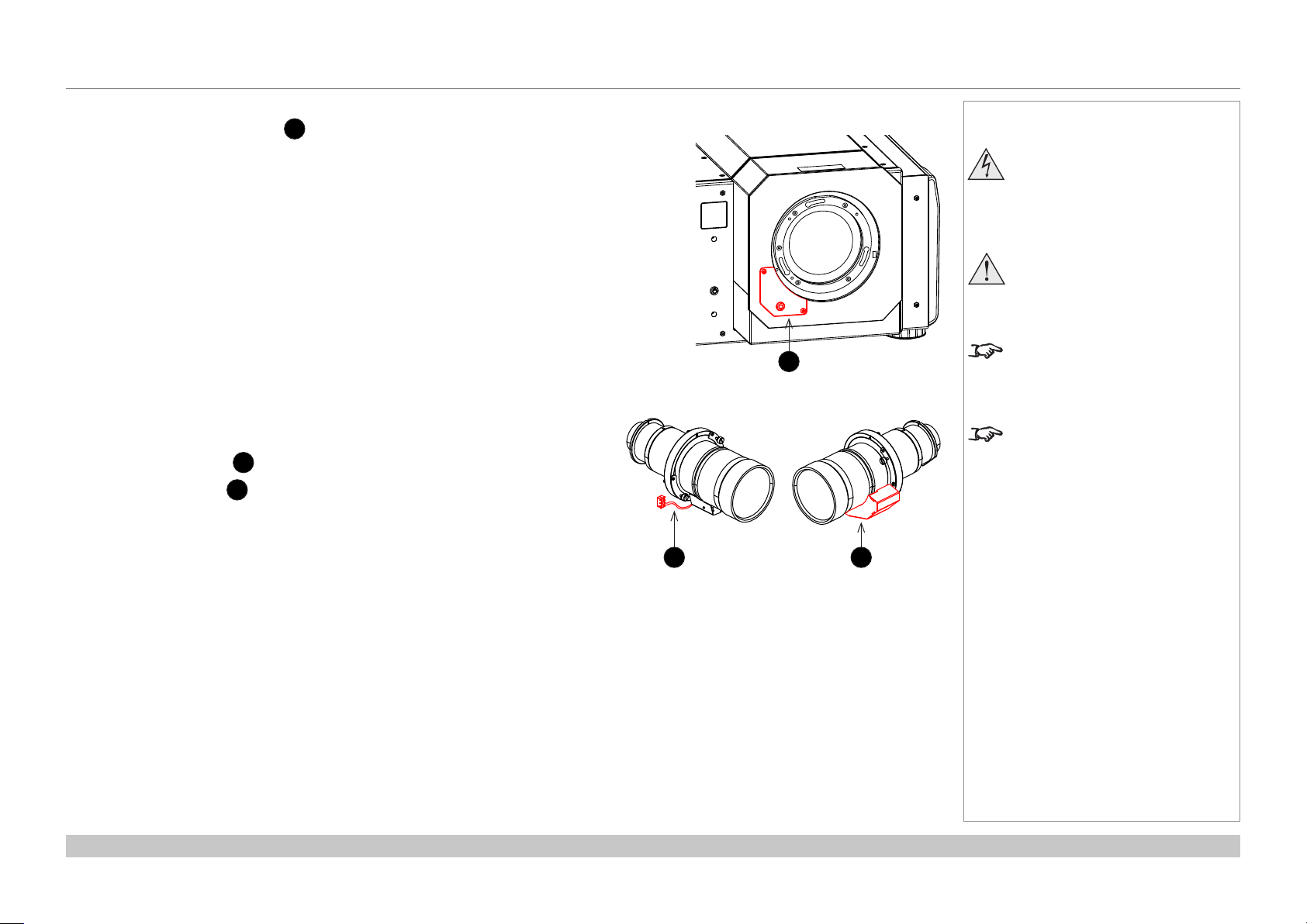
Digital Projection INSIGHT 4K Laser Series
APPENDIX G: EARLIER VERSIONS
Inserting a new lens
1. Remove the connector cover 1: it is held in position by two screws and a key.
2. Position the lens so that, if viewed from the front:
• the control cable
• the motor cover
2
is on the left
3
is on the right
Notes
Before changing the lens, always
make sure the projector is switched
off and fully disconnected from its
power supply.
When changing the lens, avoid using
excessive force as this may damage
the equipment.
1
Take care to preserve the original lens
packaging and protective caps for future
use.
The projector will not power on without
the lens tted.
Reference Guide
2 3
Rev C June 2016
page 82
Page 91

Digital Projection INSIGHT 4K Laser Series
APPENDIX G: EARLIER VERSIONS
3. Insert the lens into the mount.
Engage the three locating studs 1 into the corresponding slots 2
on the mount.
4. Rotate the lens clockwise until the studs slide all the way into the
slots.
1 2
Notes
Before changing the lens, always
make sure the projector is switched
off and fully disconnected from its
power supply.
When changing the lens, avoid using
excessive force as this may damage
the equipment.
Take care to preserve the original lens
packaging and protective caps for future
use.
The projector will not power on without
the lens tted.
5. Tighten the two xing screws 3 on the lens holder.
Reference Guide
3
3
Rev C June 2016
page 83
Page 92

Digital Projection INSIGHT 4K Laser Series
6. Insert the control cable plug into the connector socket 1.
Place the excess wire behind the front cover of the projector.
7. Replace the connector cover, making sure the cable is not trapped.
APPENDIX G: EARLIER VERSIONS
Notes
Before changing the lens, always
make sure the projector is switched
off and fully disconnected from its
power supply.
When changing the lens, avoid using
excessive force as this may damage
the equipment.
1
Take care to preserve the original lens
packaging and protective caps for future
use.
The projector will not power on without
the lens tted.
Reference Guide
Rev C June 2016
page 84
Page 93

Digital Projection INSIGHT 4K Laser Series
APPENDIX G: EARLIER VERSIONS
Removing the lens
1. Loosen the two captive screws 1 on the lens remote lock cover, then release the lock 2 using the provided key.
1
1
2
2. Remove the cover.
Notes
Before changing the lens, always
make sure the projector is switched
off and fully disconnected from its
power supply.
When changing the lens, avoid using
excessive force as this may damage
the equipment.
Take care to preserve the original lens
packaging and protective caps for future
use.
The projector will not power on without
the lens tted.
Reference Guide
Rev C June 2016
page 85
Page 94

Digital Projection INSIGHT 4K Laser Series
APPENDIX G: EARLIER VERSIONS
3. Loosen the two captive screws 3 on the lens and rotate the lens counterclockwise until it stops.
3
3
4. Unplug the remote lock connector 4 and pull the lens out of its socket.
Notes
Before changing the lens, always
make sure the projector is switched
off and fully disconnected from its
power supply.
When changing the lens, avoid using
excessive force as this may damage
the equipment.
Take care to preserve the original lens
packaging and protective caps for future
use.
The projector will not power on without
the lens tted.
Reference Guide
4
Rev C June 2016
page 86
Page 95

Digital Projection INSIGHT 4K Laser Series
APPENDIX G: EARLIER VERSIONS
Lens part numbers
Throw ratios Lens extension Part number
1.13 - 1.31 : 1 zoom lens 253 mm 116-340
1.13 - 1.66 : 1 zoom lens 270 mm 116-044
1.30 - 1.85 : 1 zoom lens 225 mm 116-045
1.45 - 2.17 : 1 zoom lens 222 mm 116-046
1.63 - 2.71 : 1 zoom lens 134 mm 116-047
1.95 - 3.26 : 1 zoom lens 137 mm 116-048
2.71 - 3.89 : 1 zoom lens 190 mm 116-049
Notes
Before changing the lens, always
make sure the projector is switched
off and fully disconnected from its
power supply.
When changing the lens, avoid using
excessive force as this may damage
the equipment.
Take care to preserve the original lens
packaging and protective caps for future
use.
The projector will not power on without
the lens tted.
Reference Guide
Rev C June 2016
page 87
Page 96

Digital Projection INSIGHT 4K Laser Series
TECHNICAL SPECIFICATIONS
Technical Specications
Digital Projection reserves the right to change product specications without prior notice.
Models
The specications on these pages refer to the following projector:
Series name
INSIGHT 4K Laser
Color system: 3-chip DLP®
Display type: 3 x 1.38” DarkChip™ DMD™
DMD™specication(native):4096 x 2160 pixels, +/- 12° tilt angle
Fast transit pixels for smooth grayscale and improved contrast.
Notes
Reference Guide
Rev C June 2016
page 88
Page 97

Digital Projection INSIGHT 4K Laser Series
TECHNICAL SPECIFICATIONS
Inputs and outputs
Type Connector Qty Type Connector Qty
Video & Computer Communication & Control
DisplayPort 1.2 DisplayPort 2 3D Sync Out BNC 1
HDMI 1.4 HDMI 1 3D Sync In BNC 1
Option Board LAN RJ45 1
3G-SDI BNC 4 RS232 9-pin D-Sub 1
DVI-D DVI-D 2 Wired Remote In 3.5 mm Stereo Jack 1
Service Port USB Type A 1
Bandwidth
N/A
Remote control and keypad
• Wired remote control
• On-board keypad with LCD screen
Automation control
• RS232
• LAN
Notes
The default hardware conguration
does not include an option board,
which can be ordered separately.
3G-SDI signals are very high
speed digital signals which require
better quality coaxial cable than
conventional analogue video. The
data rate is 3 Gigabits per second.
In choosing cable length and
connectors for any installation the
frequency response loss in decibels
should be proportional to √f, from 1
MHz, to 3 GHz.
Color temperature
• User selectable via TCGD
Reference Guide
Rev C June 2016
page 89
Page 98
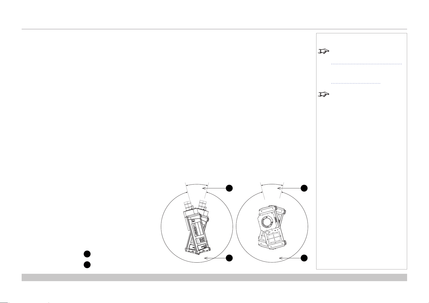
Digital Projection INSIGHT 4K Laser Series
TECHNICAL SPECIFICATIONS
Lenses
Detailed information about available lenses can be found in Appendix A: Lens Part Numbers.
Further information about lens offsets can be found in Positioning The Image > Maximum offset range.
Lens mount
• Motorised shift, zoom and focus. Intelligent Lens Memory with user-denable preset positions.
Mechanical mounting
• Front/Rear Table
• Front/Rear Ceiling
• Adjustable Front/Rear Feet
Orientation
• Table Top or Inverted: Yes
• Pointing Up: Yes, within the workable angle
30°
1
• Pointing Down: Yes
• Roll (Portrait): Yes, within the workable angle
30°
Notes
Information on lenses in this guide:
• Appendix A: Lens Part Numbers
- detailed descriptions of available
lenses.
• Maximum offset range - lens
offsets.
See also the lens calculator on the
Digital Projection website.
1
Reference Guide
1
Non-workable angle
2
Workable angle
330°
Pointing Up
2
330°
2
Roll (Portrait)
Rev C June 2016
page 90
Page 99

Digital Projection INSIGHT 4K Laser Series
TECHNICAL SPECIFICATIONS
Electrical and physical specications
• Power requirements 200-240 VAC, 50-60 Hz (single phase)
• Power Consumption 1600 W
• Thermal Dissipation 5027 BTU/hr
• Fan Noise 48 dBA
• Operating Temperature 0°C to 35°C (32 to 104F)
• Storage Temperature -10°C to 50°C (14 to 122F)
• Operating Humidity 20% to 80% non-condensing
• Weight 67 kg (148 lb)
• Dimensions H: 32.5 cm W: 70 cm L: 93.5 cm
H: 12.8 in W: 27.56 in L: 36.8 in
Safety & EMC regulations
• CE, FCC Class A, UL, CCC
Notes
Reference Guide
Rev C June 2016
page 91
Page 100

Contact Information:
Digital Projection Limited
Greenside Way, Middleton
Manchester M24 1XX, UK
Registered in England No. 2207264
Registered Ofce: as above
Tel (+44) 161 947 3300
Fax (+44) 161 684 7674
enquiries@digitalprojection.co.uk
service@digitalprojection.co.uk
www.digitalprojection.co.uk
Digital Projection Inc.
55 Chastain Road, Suite 115
Kennesaw, GA 30144, USA
Tel (+1) 770 420 1350
Fax (+1) 770 420 1360
powerinfo@digitalprojection.com
www.digitalprojection.com
116-355C INSIGHT 4K Laser Series User Manual
Digital Projection China
中国 北京市 朝阳区 芍药居北里101号
世奥国际中心A座2006室(100029)
Rm A2006
ShaoYaoJu 101 North Lane
Shi Ao International Center
Chaoyang District
Beijing 100029, PR CHINA
Tel (+86) 10 84888566
Fax (+86) 10 84888566-805
techsupport@dp-china.com.cn
www.dp-china.com.cn
Digital Projection Asia
16 New Industrial Road
#02-10 Hudson Technocentre
Singapore 536204
Tel (+65) 6284-1138
Fax (+65) 6284-1238
www.digitalprojectionasia.com
 Loading...